INSTRUCTION ANUAL SMALL MALL DIAMETER IAMETER …
24
11-24-2008 HK1103 I NSTRUCTION M ANUAL S S MALL MALL D D IAMETER IAMETER C C OLLAR OLLAR C C UTTERS UTTERS -06, -08, -10, -12 CCX (NON-SLEEVE THREADED) AND AND CCXS (SLEEVE THREADED) STYLE STYLE HYDRAULIC, AIR, & ELECTRIC
Transcript of INSTRUCTION ANUAL SMALL MALL DIAMETER IAMETER …

11-24-2008
HK1103
INSTRUCTION MANUAL
SSMALLMALL DDIAMETERIAMETER
CCOLLAROLLAR CCUTTERSUTTERS
-06, -08, -10, -12
CCX (NON-SLEEVE THREADED) ANDAND
CCXS (SLEEVE THREADED) STYLESTYLE
HYDRAULIC, AIR, & ELECTRIC

CCX & CCXS Collar Cutters Alcoa Fastening Systems
2
EU Declaration of ConformityManufacturer:
Alcoa Fastening Systems, Industrial Products Group, 1 Corporate Drive, Kingston, NY,
12401, USA
Description of Machinery:
Model numbers 4CC through 12CC series collar cutter tools
Relevant provisions complied with:
Council Directive related to Machinery (98/37/EC)
Council Directive related to EMC/EMI (2004/108/EC)
European Representative:
Rob Pattenden, Huck International, Ltd. Unit C Stafford Park 7, Telford Shropshire TF3 3BQ,
England, United Kingdom
Authorized Signature/date:
I, the undersigned, do hereby declare that the equipment specified above conforms to the
above Directive(s) and Standard(s).
Signature: ___________________________________
Full Name: Scott McIntosh
Position: Product Engineer
Installation Systems Division
Place: Kingston, New York, USA
Date: April, 2008
Sound LevelsModels: 4CC through 12CC collar cutter tools
To calculate equivalent noise level for other quantities of col-lars in an eight hour period, use the formula:Leq = SEL + 10 log (n/28,800)
where n = number of collars in eight hours.
Vibration Levels Models: 4CC through 12CC collar cutter tools
For an eight hour work day, cutting 500 typical Huck collars
will result in an equivalent weighted RMS vibration level
A(8) of:
0.41 m/s2
To calculate equivalent vibration level for other quantities ofcollars in an eight hour period, use the formula:
Equivalent Vibration Level, A8 (m/s2) = (n/480) x 0.39
where n = number of fasteners in eight hours,
and 0.39(m/s2) = Aeq for 60 seconds.
Test data to support the above information is on file at Alcoa Fastening Systems, Industrial Products Group, KingstonOperations, Kingston, NY, USA. Vibration measurements are frequency weighted in accordance with ISO 8041 (2005).
SELdB (A)
Peak ValuedB (C)
LeqdB (A)
72.8 110.2 55.2
Leq reflects the
equivalent noise
level result of cut-
ting 500 typical
Huck collars for
an eight hour
work day.

CCX & CCXS Collar Cutters Alcoa Fastening Systems
3
Page
SAFETY . . . . . . . . . . . . . . . . . . . . . . . . . . . . . . . . . . . . . . . . . . . . . . .4
DESCRIPTION . . . . . . . . . . . . . . . . . . . . . . . . . . . . . . . . . . . . . . . . . . .5
OUTLINE DIMENSIONS . . . . . . . . . . . . . . . . . . . . . . . . . . . . . . . . . . . .6
PRINCIPLE OF OPERATION . . . . . . . . . . . . . . . . . . . . . . . . . . . . . . . . .7
PREPARATION FOR USE . . . . . . . . . . . . . . . . . . . . . . . . . . . . . . . . . . .8
OPERATING INSTRUCTIONS . . . . . . . . . . . . . . . . . . . . . . . . . . . . . . . . .9
MAINTENANCE . . . . . . . . . . . . . . . . . . . . . . . . . . . . . . . . . . . . . . . .10
GOOD SERVICE PRACTICES
PREVENTIVE MAINTENANCE
SYSTEM INSPECTION
TOOL MAINTENANCE
STANDARD TOOLS AVAILABLE FROM HUCK . . . . . . . . . . . . . . . . . . . .11
ADJUSTMENTS . . . . . . . . . . . . . . . . . . . . . . . . . . . . . . . . . . . . . . . . .11
DISASSEMBLY . . . . . . . . . . . . . . . . . . . . . . . . . . . . . . . . . . . . . . . . .12
ASSEMBLY AND FILLING . . . . . . . . . . . . . . . . . . . . . . . . . . . . . . . . . .13
SUBASSEMBLIES . . . . . . . . . . . . . . . . . . . . . . . . . . . . . . . . . . . . . . .14
TOOL ASSEMBLY DRAWINGS . . . . . . . . . . . . . . . . . . . . . . . . . . . .15-19
SWITCH AND ELECTRIC CORD ASSEMBLY DRAWING . . . . . . . . . . . . . .20
AIR TRIGGER AND HOSE ASSEMBLY DRAWING . . . . . . . . . . . . . . . . . .20
HOSE AND SWITCH KIT ASSEMBLY DRAWINGS . . . . . . . . . . . . . . . . . .21
HYDRAULIC HOSES AND AIR TRIGGER ASSEMBLY DRAWING . . . . . . . .21
TROUBLESHOOTING . . . . . . . . . . . . . . . . . . . . . . . . . . . . . . . . . . . . .22
CCONTENTSONTENTS

CCX & CCXS Collar Cutters Alcoa Fastening Systems
4
SSAFETYAFETY
This instruction manual must be read,with particular attention to the followingsafety guidelines, by any person servic-ing or operating this tool.
1. Safety Glossary
WARNINGS - Must be understood to avoid
severe personal injury.
CAUTIONS - show conditions that will damageequipment and or structure.Notes - are reminders of required procedures.
Bold, Italic type and underlining - empha-
sizes a specific instruction.
2. A half hour long hands-on training session with
qualified personnel is recommended before using
Huck equipment.
3. Huck equipment must be maintained in a safe
working condition at all times. Tools and hoses
should be inspected on a regular basis for damage
or wear. Any repair should be done by a qualified
repairman trained on Huck procedures.
4. Repairman and Operator must read manual prior to
using equipment. Warning and Caution stick-
ers/labels supplied with equipment must be under-
stood before connecting equipment to any primary
power supply. As applicable, each of the sections
in this manual have specific safety and other infor-
mation.
5. Read MSDS Specifications before servicing the
tool. MSDS Specifications are available from the
product manufacturer or your Huck representative.
6. When repairing or operating Huck installation
equipment, always wear approved eye protection.
Where applicable, refer to ANSI Z87.1 - 2003
7. Disconnect primary power source before doing
maintenance on Huck equipment.
8. Tools and hoses should be inspected for leaks at
the beginning of each shift/day. If any equipment
shows signs of damage, wear, or leakage, do not
connect it to the primary power supply.
9. Mounting hardware should be checked at the
beginning of each shift/day.
10. Make sure proper power source is used at all
times.
11. Never remove any safety guards or pintail deflec-
tors.
12. Never install a fastener in free air. Personal injury
from fastener ejecting may occur.
13. When using an offset nose, always clear spent
pintail out of nose assembly before installing the
next fastener.
14. If there is a pinch point between trigger and work
piece, use remote trigger. (Remote triggers are
available for all tooling).
15. Do not abuse tool by dropping or using it as a
hammer. Never use hydraulic or air lines as a
handle or to bend or pry the tool. Reasonable
care of installation tools by operators is an impor-
tant factor in maintaining tool efficiency, eliminat-
ing downtime, and in preventing an accident
which may cause severe personal injury.
16. Never place hands between nose assembly and
work piece. Keep hands clear from front of tool.
17. Tools with ejector rods should never be cycled
with out nose assembly installed.
18. When two piece lock bolts are being used always
make sure the collar orientation is correct. See
fastener data sheet of correct positioning.
�
Product complies with requirements
set forth by the relevant European
directives.
Read manual prior to using
equipment.
Eye protection required while
using this equipment.
Hearing protection required while
using this equipment.
CCX & CCXS Collar Cutters Alcoa Fastening Systems
5
DDESCRIPTIONESCRIPTION
Series CCX-QD Hydraulic Collar Cutters are designed
to remove LGP® HUCKBOLT® fasteners with flanged
titanium collars.
Huck Hydraulic Collar Cutters are designed to be pow-
ered by Huck POWERIG® Hydraulic Units. Cutters
operate on 6000 psi (413.7 bar) PULL pressure as
supplied by POWERIG Hydraulic Units.
The CCX-QD series air triggered tools are designed
for use with Models 942 and 970 POWERIG Hydraulic
Units, or equivalent.
The CCX-QD series electric triggered tools are
designed for use with Models 913, 918 and 940, or
equivalent.
Power source must be set to correct pressure per
applicable POWERIG Hydraulic Unit instruction manu-
al.

CCX & CCXS Collar Cutters Alcoa Fastening Systems
6
���������������������
��������������
���������
��������
���
����
��
����
������
������
�������
��������
��
����
� ����
�� ���
�������
Fig. 1
OOUTLINEUTLINE D DRAWINGSRAWINGS
INCHES
millimeters

Refer to Figure 4
Hydraulic hose and trigger control cord are connected
to POWERIG Hydraulic Unit. The trigger, when
depressed, controls the PUSH stroke of the tool -
hydraulic pressure is directed to the piston and it
moves forward. Fastener removal (collar cutting)
begins as lever moves and forces collar against sta-
tionary blades; collar is cut. When collar cutting is com-
pleted, trigger is released. Spring pressure moves pis-
ton rearward to starting position, ready for the next cut-
ting cycle.
CAUTIONS
Do not abuse the tool by dropping it, using it as a ham-
mer, or otherwise causing unnecessary wear and tear.
Reasonable care of installation tools by operators is an
important factor in maintaining tool efficiency and
reducing downtime.
CCX & CCXS Collar Cutters Alcoa Fastening Systems
7
�
PPRINCIPLERINCIPLE OFOF O OPERATIONPERATION
�
WARNING: Huck recommends that only
Huck POWERIG® Hydraulic Units be used
as a power source for Huck Installation
Equipment. Hydraulic power units that deliv-
er high pressure for both PULL and
RETURN, AND ARE NOT EQUIPPED WITH
RELIEF VALVES ARE SPECIFICALLY NOT
RECOMMENDED, AND MAY BE DANGER-
OUS.
WARNINGS:
When operating Huck Installation Equipment
always wear approved eye protection.
Severe eye injury may occur if eyes are not
protected.
Tool moves forcibly while cutting collars. Be
sure there is adequate clearance for the tool
and the operator’s hands before proceeding.
Severe personal injury may result
if this precaution is not followed.
Fig. 4

CCX & CCXS Collar Cutters Alcoa Fastening Systems
8
PPREPARATIONREPARATION FORFOR U USESE
CAUTION
Keep dirt and other foreign matter out of hydraulic
systems of tools, hoses, couplers and POWERIG®
Hydraulic Unit. Do not let hose and couplers contact a
dirty floor or unclean work surface. Foreign matter in
hydraulic fluid may cause tool and POWERIG
Hydraulic Unit valves to malfunction.
Coat hose fitting threads with a non-hardening
TEFLON thread compound such as SLIC-TITE.
CAUTION
DO NOT USE TEFLON TAPE ON HOSE FITTING
THREADS. Shredded tape causes POWERIG
Hydraulic Unit valves to malfunction.
1. Use a Huck POWERIG Hydraulic Unit, or equiva-
lent, that has been prepared for operation per
applicable INSTRUCTION MANUAL, check PULL
pressure, and adjust as required.
2. Screw PULL pressure hose, with coupler nipple,
into port of tool.
3. Adjust trigger assembly on pressure hose for con-
venient position if required.
4. Connect tool hose to POWERIG Hydraulic Unit.
5. Connect trigger control cord or air line to POW-
ERIG Hydraulic Unit.
6. Connect POWERIG Hydraulic Unit to power sup-
ply (air or electric). Depress the trigger a few times
to cycle the tool and to circulate the hydraulic fluid.
Observe the action of the tool and cheek for leaks.
Disconnect tool from power supply.
CAUTION
Return pressure port of POWERIG Hydraulic Unit
must remain connected to the Hydraulic Installation
Tool or be plugged with a steel pipe plug (3/8-18
NPTF) to prevent discharge of hydraulic fluid while
using collar cutter.�
WARNING
Proper PULL pressures are important for
proper function of collar cutter, and for
operator’s safety. GAUGE SET-UP, Part
Number T-10280, is available for checking
pressure. Use instructions furnished with
T-10280 and in POWERIG Hydraulic Unit
Instruction Manual. See Table 1-
Specifications.

IMPORTANT CAUTIONS• Applicable tool must be held perpendicular to sheet. All
tool heads must be flat against sheet.• Tool must be centered on collar to assure proper cutting
action. Unequal loading of the blades caused by misalignment is the
cause of most tool malfunctions. Experience will show the most
efficient procedure in each situation. Collars must be cut on the
first attempt. Repeated cycling of the tool is likely to cause
blade damage. The blades follow the previous blade path with-
out cutting.
CAUTION: If collar is partially cut, do not force cutter overcollar. This will damage locating pins in tool pocket. See
REMOVAL OF PARTIALLY CUT COLLARS below.
CAUTION: To prevent structural and tool damage, be surethere is enough clearance for the tool to move while cut-ting collars. See appropriate dimensional drawing foramount of tool movement.
1. See Figure 5 or 6. Place tool over fastener to be removed
as shown. See all CAUTIONS. Position of the blades must
be checked prior to triggering tool.
2. Depress actuating trigger of tool; release trigger when cut-
ting action stops. Remove tool.
CAUTION: Check tool for collar segments after each cuttingstroke. Segments not removed from tool will cause damageto tool and to fastened structure.
3. If tool is adjusted correctly for the swaged condition of
the collar, one stroke will remove collar. See ADJUST-
MENT section for more detailed directions. When col-
lar is cut, but still attached to fastener, use appropri-
ate hand tools to complete collar removal.
4. Tap end of fastener with soft faced mallet to remove
from hole.
REMOVAL OF PARTIALLY CUT COLLARS See Fig. 71. Place G57F over fastener to be removed as shown.
2. Squeeze handles together closing blades around pin.
3. Move G57F handles up and down as shown in direction of
arrows until collar separates from pin.
CCX & CCXS Collar Cutters Alcoa Fastening Systems
9
OOPERATINGPERATING I INSTRUCTIONSNSTRUCTIONS
�WARNING: Tool moves forcibly while cutting
collars. Be sure there is adequate clearance
for the tool and the operator’s hands before
proceeding. Severe personal injury may
result if this precaution is not followed.
Fig. 6
Offset Collar Cutting Position
Fig. 7
Cut Collar Removal
90°
Fig. 5
Standard Collar Cutting Position
90°
90° 90°

CCX & CCXS Collar Cutters Alcoa Fastening Systems
10
MMAINTENANCEAINTENANCE
Good Service Practices
The efficiency and life of any installation or
removal tool depends upon proper maintenance
and good service practices. Tools should be serv-
iced by personnel who are thoroughly familiar with
them and how they operate.
A clean well-lighted area should be available for
servicing the tool. Special care must be taken to
prevent contamination of hydraulic systems.
All parts must be handled carefully and examined
for damage or wear. Always replace O-rings and
seals whenever the tool is disassembled for
any reason. Components should be disassembled
and assembled in a straight line without bending,
cocking or undue force. Disassembly and assem-
bly procedures outlined in this manual should be
followed.
Appropriate hand tools and soft materials to pro-
tect tool must be available. Only standard hand
tools are required. A half-inch brass drift, wood
block and vise with soft jaws will prevent damag-
ing tool.
NOTE: As experience shows, components such
as jaws should be kept on hand for repairs.
Perishable parts such as O-rings/seals should be
on hand for replacement whenever tool is disas-
sembled.
Preventive Maintenance
Refer to applicable section for ASSEMBLY and
DISASSEMBLY. For more information refer to
TROUBLESHOOTING and illustrations.
With proper care the cutter will remove 200 collars
before it may be necessary to replace the blades.
The tool area between the housing, wedge and
lever should be lubricated with NEVER-SEEZ
every fifty fasteners. After 200 fasteners the cutter
should be disassembled, cleaned in mineral spir-
its, and blown dry with compressed air. When
parts are completely dry they should be coated in
the specified areas with molybdenum disulfate
solution (suggested product is MOLY COAT #106).
When replacing a blade set it should be coated
with NEVER-SEEZ during assembly.
System Inspection
Operating efficiency of the tool is directly related to
the performance of the complete system, including
the tool, hydraulic hoses, trigger assembly and the
POWERIG® Hydraulic Unit. Therefore, an effec-
tive preventive maintenance program includes
scheduled inspections of the system to detect and
correct minor troubles.
1. Inspect tool for external damage.
2. Verify that hoses and fittings, and trigger
connections are secure.
3. Inspect hydraulic hoses for signs of damage.
Replace if required.
4. Inspect tool, hoses, and POWERIG®Hydraulic Unit during operation to detect
abnormal heating, leaks or vibration.
POWERIG® Hydraulic Unit
Maintenance
Maintenance and repair instructions are in applica-
ble POWERIG Hydraulic Unit Instruction Manuals.
Tool Maintenance
At regular intervals, depending upon use, replace
all seals in the tool. Spare seals and parts should
be kept on hand. Inspect cylinder bore and piston
for scored surfaces, excessive wear or damage,
and replace as necessary.

CCX & CCXS Collar Cutters Alcoa Fastening Systems
11
Description Used On
502865 - - Truarc®* Pliers #0200 500989; 500991
502655 - - 9/64 hex key 500054
502296 - - 3/16 hex key 119513; 123703
CAUTION: Rub Slic-Tite®* TEFLON®* thread compound, or equivalent, on pipe threads to aid assemblyand sealing. DO NOT USE TEFLON TAPE ON PIPE THREADS.
502723 - - SUPER O-LUBE (Parker Seal Co.)
505565 - - Never-Seez®*505124 - - VIBRATITE (ND Industries)
503237 - - Slic-Tite®*MOLYKOTE #106 (Dow Corning Co. - available locally)
* Slic-Tite is a registered trademark of LA-CO Industries, Inc.* TEFLON is a registered trademark of DuPont Corp.* TRUARC is a trademark of TRUARC Co. LLC* Never-Seez is a registered trademark of Bostik, Inc.
SSTANDARDTANDARD T TOOLSOOLS A AVAILABLEVAILABLE FROMFROM H HUCKUCK
AADJUSTMENTSDJUSTMENTSCollar cutter is designed to remove a fully swaged
collar in one stroke when adjusted with gage that
is supplied with tool. Cutter can be adjusted to cut
partially swaged collars by increasing opening
between lever and blades.
NOTE: See applicable tool drawing for gagepart number. Check fastener size.
Lever adjustment on fully swaged collar.
1. Adjust gap opening between blades and lever
by inserting a 3/16 hex key through hole in end
cap and into piston hex. Turning key moves
wedge and lever simultaneously. Adjust until a
slight interference is felt on the flange diameter
of collar between blade and lever.
2. Check tool on a test plate with properly
installed fasteners. See ADDITIONAL PROCE-DURES AFTER ADJUSTMENT.
3. Fill tool with fluid and replace hose kit.
Lever Adjustment on partially swaged collar.
Simulate the partially swaged condition by
installing fasteners in a test plate. Using spacers
(shim stock) equally spaced under the anvil of the
nose assembly. Install fasteners with various
shims until desired partial swage is obtained.
1. Follow instructions 1, 2 & 3 above for fully
swaged collars. Remove gage.
Additional Procedures after Adjustment
After final adjustments have been made, if collar
can not be cut with one stroke, remove collar with
appropriate hand tools. See Figure 7.
If increased efficiency is required, more than one
cutter can be used: One adjusted to cut fully
swaged collars and another one adjusted to cut
partially swaged collars.
CCX & CCXS Collar Cutters Alcoa Fastening Systems
12
DDISASSEMBLYISASSEMBLY
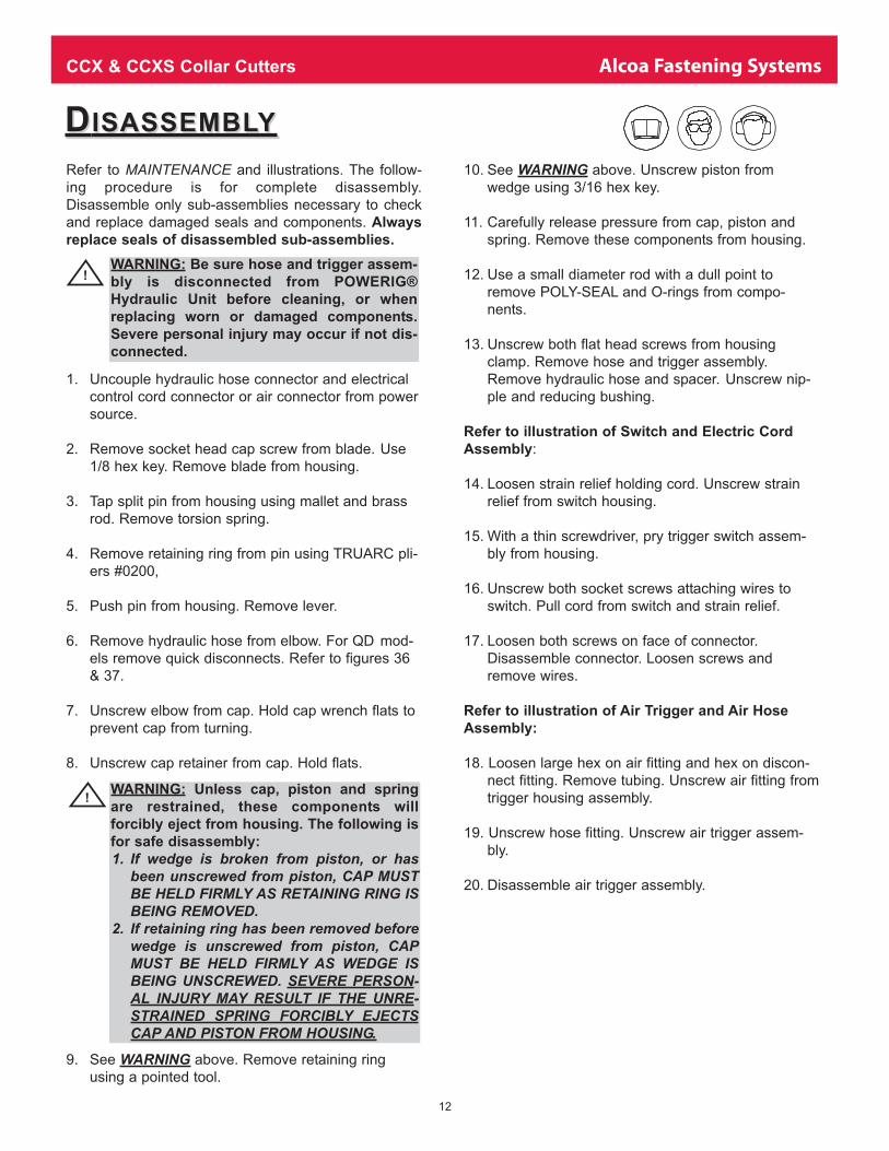
Refer to MAINTENANCE and illustrations. The follow-
ing procedure is for complete disassembly.
Disassemble only sub-assemblies necessary to check
and replace damaged seals and components. Always
replace seals of disassembled sub-assemblies.
1. Uncouple hydraulic hose connector and electrical
control cord connector or air connector from power
source.
2. Remove socket head cap screw from blade. Use
1/8 hex key. Remove blade from housing.
3. Tap split pin from housing using mallet and brass
rod. Remove torsion spring.
4. Remove retaining ring from pin using TRUARC pli-
ers #0200,
5. Push pin from housing. Remove lever.
6. Remove hydraulic hose from elbow. For QD mod-
els remove quick disconnects. Refer to figures 36
& 37.
7. Unscrew elbow from cap. Hold cap wrench flats to
prevent cap from turning.
8. Unscrew cap retainer from cap. Hold flats.
9. See WARNING above. Remove retaining ring
using a pointed tool.
10. See WARNING above. Unscrew piston from
wedge using 3/16 hex key.
11. Carefully release pressure from cap, piston and
spring. Remove these components from housing.
12. Use a small diameter rod with a dull point to
remove POLY-SEAL and O-rings from compo-
nents.
13. Unscrew both flat head screws from housing
clamp. Remove hose and trigger assembly.
Remove hydraulic hose and spacer. Unscrew nip-
ple and reducing bushing.
Refer to illustration of Switch and Electric Cord
Assembly:
14. Loosen strain relief holding cord. Unscrew strain
relief from switch housing.
15. With a thin screwdriver, pry trigger switch assem-
bly from housing.
16. Unscrew both socket screws attaching wires to
switch. Pull cord from switch and strain relief.
17. Loosen both screws on face of connector.
Disassemble connector. Loosen screws and
remove wires.
Refer to illustration of Air Trigger and Air Hose
Assembly:
18. Loosen large hex on air fitting and hex on discon-
nect fitting. Remove tubing. Unscrew air fitting from
trigger housing assembly.
19. Unscrew hose fitting. Unscrew air trigger assem-
bly.
20. Disassemble air trigger assembly.
�WARNING: Unless cap, piston and spring
are restrained, these components will
forcibly eject from housing. The following is
for safe disassembly:
1. If wedge is broken from piston, or hasbeen unscrewed from piston, CAP MUSTBE HELD FIRMLY AS RETAINING RING ISBEING REMOVED.
2. If retaining ring has been removed beforewedge is unscrewed from piston, CAPMUST BE HELD FIRMLY AS WEDGE ISBEING UNSCREWED. SEVERE PERSON-AL INJURY MAY RESULT IF THE UNRE-STRAINED SPRING FORCIBLY EJECTSCAP AND PISTON FROM HOUSING.
�WARNING: Be sure hose and trigger assem-
bly is disconnected from POWERIG®
Hydraulic Unit before cleaning, or when
replacing worn or damaged components.
Severe personal injury may occur if not dis-
connected.

CCX & CCXS Collar Cutters Alcoa Fastening Systems
13
AASSEMBLYSSEMBLY ANDAND F FILLINGILLING C CUTTERUTTERClean all components with mineral spirits, and inspect
for wear or damage. Replace as necessary. Replace all
seals on/in disassembled components. Use O-ring
and POLYSEAL supplied in Service Kit 6/8CCFTKIT.
See applicable service kit parts list. Smear LUBRIPLATE
130AA or PARKER O-LUBE on O-ring, POLYSEAL and
mating components to facilitate assembly. Assemble tool
taking care not to damage O-ring or POLYSEAL. To pur-
chase standard parts locally, see NOTES AND SPECIFI-CATIONS FOR STANDARD COMPONENTS for specific
information.
CAUTION: REMOVE ELASTOMER SPRING FROMPOLY-SEAL PRIOR TO ASSEMBLY IN TOOL.
Refer to illustration of Air Trigger and Air Hose Assy
1. Assemble air trigger assembly.
2. Screw hose fitting into housing. Screw air trigger
assembly into housing. Tighten both parts.
3. Start air fitting onto hose fitting. Push tubing into fit-
ting. Tighten fitting.
4. Push other end of tubing into disconnect fitting and
tighten.
Refer to illustration of Switch and Electric Cord Assy
5. With connector disassembled, push cord through top
of connector. Push both wires into holes in base and
tighten both retaining screws.
6. Squeeze assembled base and top together until both
connecting screws are seated. Continue tightening
screws until cord is firmly gripped.
7. Screw strain relief into housing and tighten.
8. Push cord through strain relief. Push each wire into
an attaching hole in back of electric switch assembly
and tighten both screws.
9. Lubricate O-ring, and using arbor press, press elec-
tric switch into housing. Tighten strain relief on cord.
10. Position air trigger hose/electric switch cord and
hose spacer in lower half of housing clamp. Put
hydraulic hose in clamp near cutter end of hose.
Allow a little extra space on hose so hose guard can
be pulled back to allow access to hex hose fitting.
11. Place upper half of housing clamp over components
in lower half. Join halves together with two screws,
Iockwashers and nuts. When components are prop-
erly aligned, tighten screws.
12. Hold housing in a soft jawed vise.
13. Slide spring over piston. Push piston into housing.
Hold cylinder cap against back of piston and push
both into housing until retainer can be installed.
14. Screw retainer cap onto cylinder cap and tighten.
15. Apply VIBRATITE to piston threads. Hold wedge in
position in housing. Screw piston onto wedge. Use
3/16 hex key inserted through back of cap.NOTE:
Apply NEVER-SEEZ and Moly-Disulfide (MOLY
COAT #106) to contact surfaces between wedge and
lever. See illustration.
16. Hold lever in position in housing.
17. Push pin through housing and lever. With TRUARC
Pliers #0200, install retaining ring.
18. Position torsion spring in housing and tap split pin
through housing and spring.
19. Place blade in housing and install cap screw. Use
1/8 hex key.
NOTE: Tool lever adjustment must be done before
elbow is attached to tool. See ADJUSTMENTS.
20. Screw in elbow after lever adjustment has been
completed. Use TEFLON thread compound and
tighten connection.
NOTE: Elbow may be omitted and hose installed
directly into cylinder cap. This configuration pro-
vides advantages with some structural forms.
21. Install hose assembly into elbow. For QD models
install quick disconnects.
22. To prevent air being trapped in tool and causing loss
of hydraulic pressure, fill hydraulic hose and tool
with hydraulic fluid before screwing hose into elbow.
Use TEFLON thread compound. Install six cable
ties, P/N 505839, on hose and cord. Space ties
equally.
Fig. 9
Lever and
Wedge
Lubrication

CCX & CCXS Collar Cutters Alcoa Fastening Systems
14
6CCX-QD, 8CCX-QD, & 8CCXS-QD
128884 - Piston Assembly contains: Piston,
(not available separately) and
Polyseal
128878 - End Cap &
Swivel Assembly Fig. 10
10CCX-QD & 12CCX-QD
128970 - Piston Assembly contains: Piston,
(not available separately) and
Polyseal
128951 - End Cap &
Swivel Assembly Fig. 11
SSUBASSEMBLYUBASSEMBLY P PARTART N NUMBERSUMBERS
ANDAND D DRAWINGSRAWINGS
������������� ������������
����������
��� ����������
���� �������
�� ��������
�������������������
���������� !"#�"$�
����%�����
���%�&������'���
���%���(������
Fig. 10
����������� ��������������
����������
���� ���������
�� ���������
�����������
���� ��������������
�� ���� ��!"#$�#%�!
����& ����
���&��������'���
���&����(����
Fig. 11

CCX & CCXS Collar Cutters Alcoa Fastening Systems
15
������
����
������
������
��� � �
������
������
������
������
����
������
������
����
������
������
�����
������
���� �
������
���� �
��� ��
���� �!���
������!" �!���
#!���$��!%��&
������ '� ������
(��� � �!(� �
����
����
�
������
)�$��
������
*���
������
+�����
���� �
������
����!'� ������
�����
�����
'���
����
��������
������
'��&����
������
������
,�����
������
-���!'���
,�����
������
������
���&
������
(�����
��.� �
������
�����
������
�
���
���
��
�
��� �� ���
Fig. 12
CCX & CCXS Collar Cutters Alcoa Fastening Systems
16
������
����
������
������
��� � �
������
������
������
������
����
������
������
����
������
������
�����
������
���� �
������
���� �
��� ��
���� �!���
������!" �!���
#!���$��!%��&
������ '� ������
(��� � �!(� �
����
����
�
������
)�$��
������
*���
������
+�����
���� �
������
����!'� ������
�����
�����
'���
����
��������
������
'��&����
������
������
,�����
������
-���!'���
,�����
������
������
���&
������
(�����
��.� �
������
�����
������
�
���
���
��
�
��� �� ���
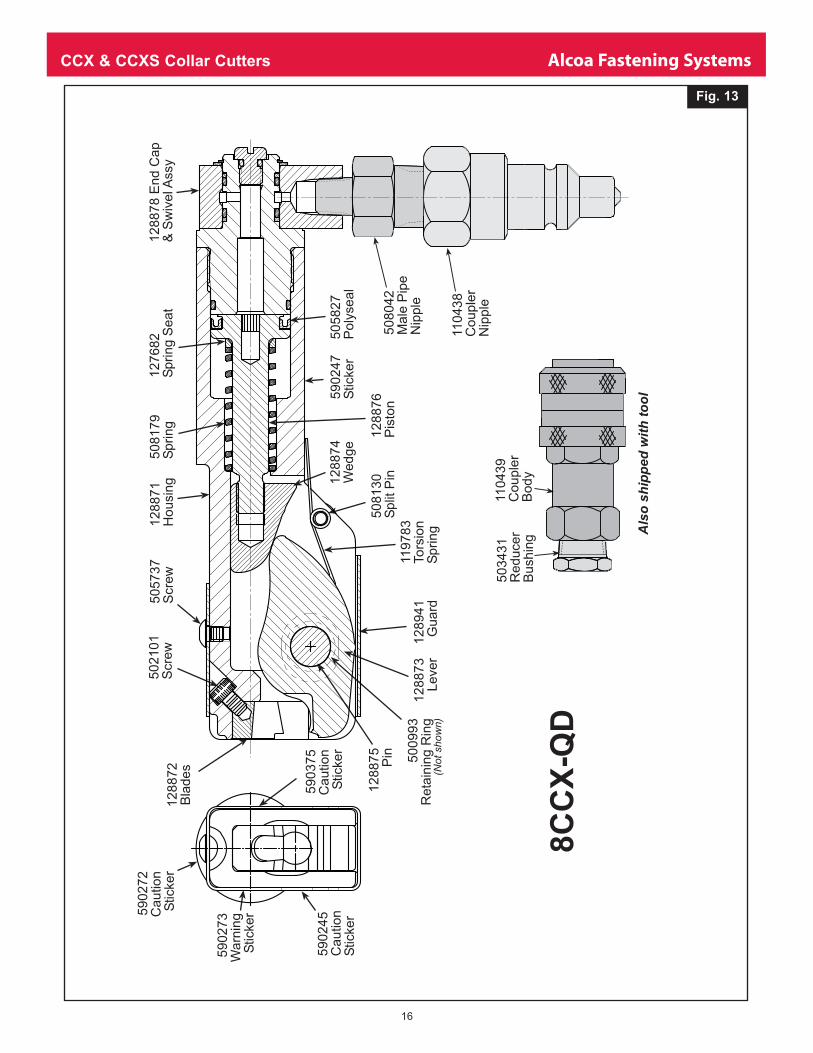
Fig. 13

CCX & CCXS Collar Cutters Alcoa Fastening Systems
17
������
����
������
������
��� � �
������
������
������
������
����
������
������
����
������
������
�����
������
���� �
������
� �� �
������
� �� �!���
������!" �!��
#!���$��!%��&
������ '� ������
(��� � �!(� �
����
����
�
������
)�$��
������
*���
������
+�����
� �� �
������
� ��!'� ������
�����
������
'���
����
��������
������
'��&����
������
�� ���
,� ��
������
-���!'� �
,� ��
������
�� ���
���&
������
(�����
��.� �
������
�����
�������
�
���
���
��
�
��� �� ���
Fig. 14

CCX & CCXS Collar Cutters Alcoa Fastening Systems
18
����
���
���
�
����
���
����
���
���
����
���
���
�
����
�
����
���
����
����
���
���
���
����
���
� �
����
�� !
� �
��"
��
�#��
$��
%
����
�� &� ��
����
'�
�� �
� '
� �
����
����
�
����
��(�
#��
����
��)
���
����
��*�
����
�
���
�
����
���
���
&� ��
����
+��
����
����
&��
�
����
���
����
�����
��&
��%�
���
����
���
���
��,
����
�
����
��-
���
&��
�,
����
�
����
���
���
���
��%
����
��'
���
���
�.�
�
����
���
����
�������
�
���
���
��
�
��� �� ���
Fig. 15

CCX & CCXS Collar Cutters Alcoa Fastening Systems
19
������
����
������
������
������
������
����
������
������
�����
������
���� �
������
���� �
������� �����
!����"���#��$
������ %� ������
&��� � ��&� �
����
����
�
������
'�"��
������
(���
������
)�����
���� �
����*�
�����%� ��
����
+����
������
%���
������
���������*��
%��$����
����*�
������
,�����
������
-����%���
,�����
����*�
������
���$
��*�*�
&�����
��.� �
����*�
�����
�������
�
���
���
��
�
��� �� ���
Fig. 16
CCX & CCXS Collar Cutters Alcoa Fastening Systems
20
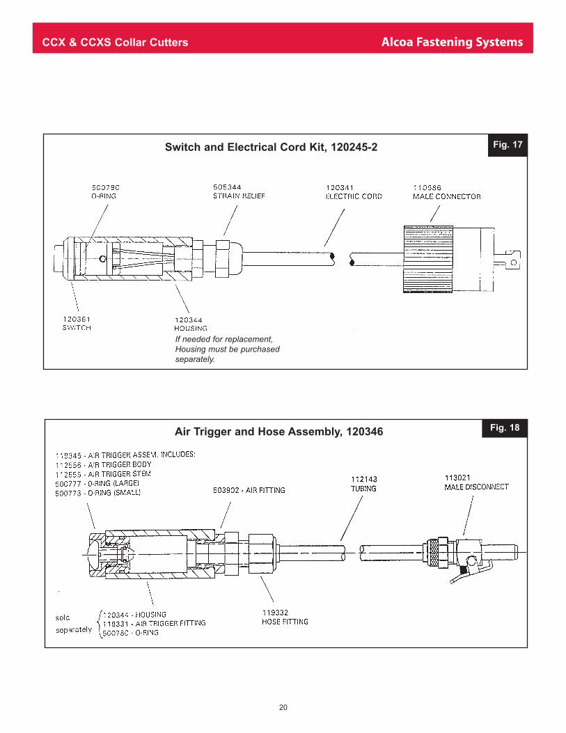
Fig. 17
Fig. 18Air Trigger and Hose Assembly, 120346
Switch and Electrical Cord Kit, 120245-2
If needed for replacement,Housing must be purchasedseparately.

CCX & CCXS Collar Cutters Alcoa Fastening Systems
21
����� �������������������
����
����������������
�� �� ����!"�������#�����$�� �%�����!" ���� �����&�' ��� ��(��)�*����&�' ������+���&�'
����� ���"�+�""�
�����,����#-.����#-
�� %��/�0�������
0��
Fig. 19
Hose and Switch Kit, 120347
����� ������������������������
�������������������
����������� ����
!�����"����#�$��%�#�
����&����'������
Fig. 20
Hydraulic Hoses and Air Trigger Assembly, 120348

CCX & CCXS Collar Cutters Alcoa Fastening Systems
22
TTROUBLESHOOTINGROUBLESHOOTING
Always check the simplest possible cause of a malfunction first. For example, a loose or
disconnected trigger line. Then proceed logically, eliminating each possible cause until
the defective part is located. Where possible, substitute known good parts for suspected
defective parts. Use chart as an aid for locating and correcting trouble.
1. Cutter fails to operate when trigger is depressed.
a. Inoperative POWERIG® Hydraulic Unit. See
applicable instruction manual.
b. Loose air or electric connections.
c. Damaged trigger assembly.
d. Loose or faulty hydraulic hose couplings.
2. Cutter blades do not cut through collar.
a. Reversed hydraulic hose connections between
POWERIG Hydraulic Unit and collar cutter.
3. Cutter leaks hydraulic fluid.
a. Defective seals or loose hose connections at
tool.
4. Hydraulic couplers leak fluid.
a. Damaged or worn O-rings in coupler body. See
illustration.
5. Hydraulic fluid overheats.
a. POWERIG Hydraulic Unit not operating proper-
ly.
b. Pump motor rotation reversed.
6. Cutter operates erratically and fails to cut collar
quickly.
a. Low or erratic hydraulic pressure supply. Air in
system.
b. Damaged or worn piston POLYSEAL in cutter.
c. Excessive wear on sliding surfaces of tool
parts.
d. Excessive wear of blades or damage.
7. Cutter blades fail to open when trigger is released.
a. Return spring is weak or broken.

CCX & CCXS Collar Cutters Alcoa Fastening Systems
23
LIMITED WARRANTIES
Tooling Warranty: Huck warrants that tooling and other
items (excluding fasteners, and hereinafter referred as
"other items") manufactured by Huck shall be free from
defects in workmanship and materials for a period of nine-
ty (90) days from the date of original purchase.
Warranty on "non standard or custom manufactured
products": With regard to non-standard products or cus-
tom manufactured products to customer's specifications,
Huck warrants for a period of ninety (90) days from the
date of purchase that such products shall meet Buyer's
specifications, be free of defects in workmanship and
materials. Such warranty shall not be effective with
respect to non-standard or custom products manufactured
using buyer-supplied molds, material, tooling and fixtures
that are not in good condition or repair and suitable for
their intended purpose.
THERE ARE NO WARRANTIES WHICH EXTEND
BEYOND THE DESCRIPTION ON THE FACE HEREOF.
HUCK MAKES NO OTHER WARRANTIES AND
EXPRESSLY DISCLAIMS ANY OTHER WARRANTIES,
INCLUDING IMPLIED WARRANTIES AS TO MER-
CHANTABILITY OR AS TO THE FITNESS OF THE
TOOLING, OTHER ITEMS, NONSTANDARD OR CUS-
TOM MANUFACTURED PRODUCTS FOR ANY PARTIC-
ULAR PURPOSE AND HUCK SHALL NOT BE LIABLE
FOR ANY LOSS OR DAMAGE, DIRECTLY OR INDI-
RECTLY, ARISING FROM THE USE OF SUCH TOOL-
ING, OTHER ITEMS, NONSTANDARD OR CUSTOM
MANUFACTURED PRODUCTS OR BREACH OF WAR-
RANTY OR FOR ANY CLAIM FOR INCIDENTAL OR
CONSEQUENTIAL DAMAGES.
Huck's sole liability and Buyer's exclusive remedy for any
breach of warranty shall be limited, at Huck's option, to
replacement or repair, at FOB Huck's plant, of Huck man-
ufactured tooling, other items, nonstandard or custom
products found to be defective in specifications, workman-
ship and materials not otherwise the direct or indirect
cause of Buyer supplied molds, material, tooling or fix-
tures. Buyer shall give Huck written notice of claims for
defects within the ninety (90) day warranty period for tool-
ing, other items, nonstandard or custom products
described above and Huck shall inspect products for which
such claim is made.
Tooling, Part(s) and Other Items not manufactured by
Huck.
HUCK MAKES NO WARRANTY WITH RESPECT TO
THE TOOLING, PART(S) OR OTHER ITEMS MANUFAC-
TURED BY THIRD PARTIES. HUCK EXPRESSLY DIS-
CLAIMS ANY WARRANTY EXPRESSED OR IMPLIED,
AS TO THE CONDITION, DESIGN, OPERATION, MER-
CHANTABILITY OR FITNESS FOR USE OF ANY TOOL,
PART(S), OR OTHER ITEMS THEREOF NOT MANU-
FACTURED BY HUCK. HUCK SHALL NOT BE LIABLE
FOR ANY LOSS OR DAMAGE, DIRECTLY OR INDI-
RECTLY, ARISING FROM THE USE OF SUCH TOOL-
ING, PART(S) OR OTHER ITEMS OR BREACH OF
WARRANTY OR FOR ANY CLAIM FOR INCIDENTAL
OR CONSEQUENTIAL DAMAGES.
The only warranties made with respect to such tool, part(s)
or other items thereof are those made by the manufactur-
er thereof and Huck agrees to cooperate with Buyer in
enforcing such warranties when such action is necessary.
Huck shall not be liable for any loss or damage resulting
from delays or nonfulfillment of orders owing to strikes,
fires, accidents, transportation companies or for any rea-
son or reasons beyond the control of the Huck or its sup-
pliers.
Huck Installation Equipment
Huck International, Inc. reserves the right to make
changes in specifications and design and to discontinue
models without notice.
Huck Installation Equipment should be serviced by trained
service technicians only.
Always give the Serial Number of the equipment when cor-
responding or ordering service parts.
Complete repair facilities are maintained by Huck
International, Inc. Please contact one of the offices listed
below.
Eastern
One Corporate Drive Kingston, New York 12401-0250
Telephone (845) 331-7300 FAX (845) 334-7333
Canada
6150 Kennedy Road Unit 10, Mississauga, Ontario,
L5T2J4, Canada.
Telephone (905) 564-4825 FAX (905) 564-1963
Outside USA and Canada
Contact your nearest Huck International Office, see back
cover.
In addition to the above repair facilities, there are
Authorized Tool Service Centers (ATSC's) located
throughout the United States. These service centers offer
repair services, spare parts, Service Parts Kits, Service
Tools Kits and Nose Assemblies. Please contact your
Huck Representative or the nearest Huck office listed on
the back cover for the ATSC in your area.

Americas
Alcoa Fastening SystemsAerospace ProductsTucson Operations3724 East ColumbiaTucson, AZ 85714800-234-4825520-747-9898FAX: 520-748-2142
Alcoa Fastening SystemsAerospace ProductsCarson OperationsPO Box 5268900 Watson Center Rd.Carson, CA 90749800-421-1459310-830-8200FAX: 310-830-1436
Alcoa Fastening SystemsCommercial ProductsWaco OperationsPO Box 81178001 Imperial DriveWaco, TX 76714-8117800-388-4825254-776-2000FAX: 254-751-5259
Alcoa Fastening SystemsCommercial ProductsKingston Operations1 Corporate DriveKingston, NY 12401800-431-3091845-331-7300FAX: 845-334-7333www.hucktools.com
Alcoa Fastening SystemsCommercial ProductsCanada Operations6150 Kennedy Road, Unit 10Mississagua, Ontario L5T2J4Canada905-564-4825FAX: 905-564-1963
Alcoa Fastening SystemsCommercial ProductsLatin America OperationsAvenida Parque Lira. 79-402Tacubaya Mexico, D.F.C.P. 11850FAX: 525-515-1776TELEX: 1173530 LUKSME
Far East
Alcoa Fastening SystemsCommercial ProductsAustralia Operations14 Viewtech PlaceRowville, Victoria Australia 317803-764-5500Toll Free: 008-335-030FAX: 03-764-5510
Europe
Alcoa Fastening SystemsCommercial ProductsUnited Kingdom OperationsUnit C, Stafford Park 7Telford, ShropshireEngland TF3 3BQ01952-290011FAX: 0952-290459
Alcoa Fastening SystemsAerospace ProductsFrance OperationsClos D’AssevilleBP495450 Us Par VignyFrance33-1-30-27-9500FAX: 33-1-34-66-0600
For the Long Haul™
A Global OrganizationAlcoa Fastening Systems (AFS) maintains companyoffices throughout the United States and Canada,with subsidiary offices in many other countries.Authorized AFS distributors are also located inmany of the world’s
industrial and Aerspace centers, where they providea ready source of AFS fasteners, installation tools,tool parts, and application assistance.
For The Long Haul, The Future of Fastening Technology, The Future of Assembly Technology, The Future of ToolingTechnology, and Tools of Productivity are service marks of HuckInternational. Huck provides technical assistance regarding the useand application of Huck fasteners and tooling.
NOTICE: The information contained in this publication is only forgeneral guidance with regard to properties of the products shown
and/or the means for selecting such products, and is not intendedto create any warranty, express, implied, or statutory; all warrantiesare contained only in Huck’s written quotations, acknowledge-ments, and/or purchase orders. It is recommended that the usersecure specific, up-to-date data and information regarding eachapplication and/or use of such products.
HWB898 1003-5M
© 2003 Alcoa Fastening Systems
1 Corporate Drive, Kingston, NY 12401 • Tel: 800-431-3091 • Fax: 845-334-7333 • E-mail: [email protected] • www.alcoafasteningsystems.com
Alcoa Fastening Systems world-wide locations:
One Great ConnectionSM
������������ ����������
������������ ���
������������ ���������
������������ ���