Institutional Commercial Remote
32
ICR Institutional Commercial Remote For Use with Hunter Controllers Owner’s Manual and Installation Instructions ENGLISH/ESPAÑOL ® ICR ® OFF ON MODE
-
Upload
phungkhanh -
Category
Documents
-
view
213 -
download
0
Transcript of Institutional Commercial Remote

ICRInstitutional Commercial Remote
For Use with Hunter Controllers
Owner’s Manual andInstallation Instructions
ENGLISH/ESPAÑOL
® icr
®
OFF ONMODE

Table of conTenTs .....................................................................................Introduction................................................................................................................................................................... 1ICR.Components............................................................................................................................................................ 2SmartPort®.Wiring.Harness............................................................................................................................................. 4Installing.the.SmartPort®.Wiring.Harness........................................................................................................................ 4Wiring.the.SmartPort®.to.Hunter.Controllers................................................................................................................... 5Typical.Installations........................................................................................................................................................ 6Preparing.the.Transmitter.for.Use................................................................................................................................... 6Installing.the.Transmitter.Battery.................................................................................................................................... 7Changing.the.Run.Time................................................................................................................................................... 7Changing.the.Transmitter.Address................................................................................................................................... 8Changing.the.Maximum.Station.Number.......................................................................................................................... 8Preparing.the.Receiver.for.Use........................................................................................................................................ 9Changing.the.Receiver.Address....................................................................................................................................... 9Activating.a.Station.with.the.ICR................................................................................................................................... 10Maximizing.Operating.Range......................................................................................................................................... 11Troubleshooting.Guide.................................................................................................................................................. 12Specifications............................................................................................................................................................... 13

Tabla de conTenido ...................................................................................Presentación.del.Producto............................................................................................................................................ 15Componentes.del.ICR................................................................................................................................................... 16Conexión.de.Cableado.del.Programador.SmartPort®....................................................................................................... 18Instalación.del.Arnés.de.Cableado.SmartPort................................................................................................................. 18Conexión.de.Cableado.del.Programador.SmartPort®........................................................................................................ 19Instalaciones.Típicas.................................................................................................................................................... 20Preparación.del.Emisor.Antes.de.su.Uso....................................................................................................................... 20Colocación.de.la.Pila.del.Emisor.................................................................................................................................... 21Cambio.del.Tiempo.del.Ciclo.de.Riego........................................................................................................................... 21Modificación.de.la.Dirección.del.Emisor........................................................................................................................ 22Modificación.del.Número.Máximo.de.Estaciones............................................................................................................ 22Preparación.del.Receptor.Antes.de.su.Uso.................................................................................................................... .23Modificación.de.la.Dirección.del.Receptor..................................................................................................................... 23Activación.de.una.Estación.por.Medio.del.Sistema.de.Mando.a.Distancia.ICR................................................................. 24Optimización.de.la.Zona.de.Funcionamiento................................................................................................................... 25Guía.Para.Solucionar.Problemas................................................................................................................................... 26Datos.Técnicos............................................................................................................................................................. 27
�
inTroducTion ...............................................................................................Finally.there’s.an.affordable.remote.control.system.designed.with.the.commercial.irrigation.contractor.in.mind..Hunter.is.pleased.to.introduce.the.Institutional.Commercial.Remote.(ICR)..This.rugged.remote.design.offers.similar.functionality.as.our.SRR.remote,.but.with.longer.range.capability..
With.the.ICR.there’s.no.need.to.walk.back.and.forth.to.the.controller.to.conduct.manual.watering.operations.when.doing.maintenance.or.repair.work.on.your.irrigation.systems..Also,.winterization.can.be.done.quickly.and.easily.with.one.worker.instead.of.two..
The.ICR.is.designed.to.be.rugged,.and.water.resistant..Its.large.LCD.display.and.push.button.design.makes.it.easy.to.operate..Best.of.all,.with.an.operating.range.from.½.to.1.mile,.you’ll.be.able.to.conduct.remote.operations.on.even.the.largest.irrigation.systems.
The.following.instructions.provide.information.on.installing,.setting.up,.and.operating.your.ICR.

�
icr componenTs .............................................................................................
ICR
OFF ONMODE
®
A
2
3
4
1
B D
C
5
7
86
9
�
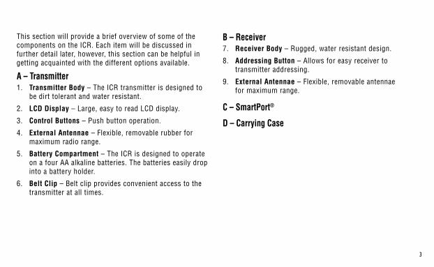
B – Receiver7.. Receiver Body.–.Rugged,.water.resistant.design.
8.. Addressing Button.–.Allows.for.easy.receiver.to..transmitter.addressing..
9.. External Antennae.–.Flexible,.removable.antennae..for.maximum.range.
C – SmartPort®
D – Carrying Case
This.section.will.provide.a.brief.overview.of.some.of.the.components.on.the.ICR..Each.item.will.be.discussed.in.further.detail.later,.however,.this.section.can.be.helpful.in.getting.acquainted.with.the.different.options.available.
A – Transmitter1.. Transmitter Body.–.The.ICR.transmitter.is.designed.to.
be.dirt.tolerant.and.water.resistant..
2.. LCD Display.–.Large,.easy.to.read.LCD.display..
3.. Control Buttons.–.Push.button.operation.
4.. External Antennae.–.Flexible,.removable.rubber.for.maximum.radio.range.
5.. Battery Compartment.–.The.ICR.is.designed.to.operate.on.a.four.AA.alkaline.batteries..The.batteries.easily.drop.into.a.battery.holder.
6.. Belt Clip.–.Belt.clip.provides.convenient.access.to.the.transmitter.at.all.times.
ICR
OFF ONMODE
®
A
2
3
4
1
B D
C
5
7
86
9

�
To.utilize.the.ICR.remote.control.system,.your.controller.must.be.equipped.with.a.SmartPort.wiring.harness..This.wiring.harness.provides.the.communication.port.where.the.ICR.receiver.is.attached..The.SmartPort.can.be.connected.to.Hunter.SRC,.Pro-C.and.ICC.controllers..A.SmartPort.wiring.harness.is.provided.with.your.ICR.remote.system..The.typical.SmartPort.location.is.approximately.12".below.the.controller..The.recommended.installation.procedure.for.this.location.would.be.as.follows:
smartport® Wiring Harness .......................................................................
insTalling THe smartport Wiring Harness ........................................1.. Install.a.½".female.threaded.“Tee”.in.the.field.wiring.
conduit.approximately.12".below.the.controller.2.. Feed.the.red,.white,.and.blue.wires.of.the.SmartPort.
through.the.base.of.the.“Tee”.and.into.the.controller.wiring.compartment.as.shown.in.the.following.figures..
NOTE: The harness may be installed outdoors by bringing the conduit through an exterior wall, then installing the appropriate fitting.
NOTE: For installations where the receiver will be installed permanently on an outside wall, make certain that the SmartPort is the version with an o-ring seal.
1/2" Thread
To Controller
Pre-assembled Assembled

�
SRC Controller SmartPort InstallationAccess.the.terminal.strip.area.and.attach.the.red.wire.to.the.left.AC.screw.slot,.attach.the.white.wire.to.the.next.AC.screw.slot.and.attach.the.blue.wire.to.the.screw.slot.marked.“R”.
Pro-C Controller SmartPort InstallationAccess.the.terminal.strip.area.on.the.main.module.and.attach.the.red.wire.to.the.bottom.most.AC.screw.slot,.attach.the.white.wire.to.the.upper.AC.screw.slot.and.attach.the.blue.wire.to.the.screw.slot.marked.“REM”.
ICC Controller SmartPort InstallationAccess.the.terminal.strip.area.on.the.power.module.and.attach.the.red.wire.to.the.bottom.most.AC.screw.slot,.attach.the.white.wire.to.the.upper.AC.screw.slot.and.attach.the.blue.wire.to.the.screw.slot.marked.“REM”.
Wiring THe smartport® To HunTer conTrollers ..............................
NOTE: Hunter ACC controllers are provided with the SmartPort® Factory installed.
Red
Blue
White
BlueWhiteRed
AC AC R RS C MV 1 2 3 4 5 6
White
Blue
Red
�
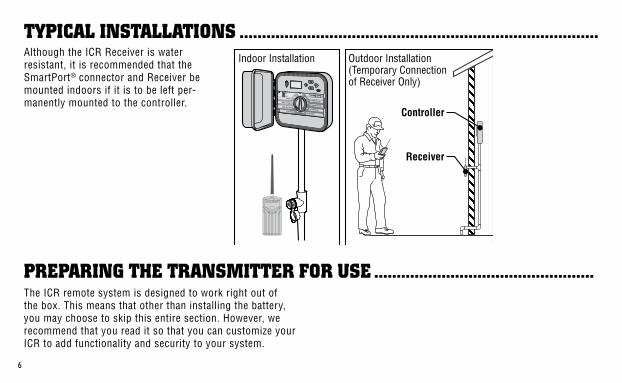
Although.the.ICR.Receiver.is.water.resistant,.it.is.recommended.that.the.SmartPort®.connector.and.Receiver.be.mounted.indoors.if.it.is.to.be.left.per-manently.mounted.to.the.controller.
Typical insTallaTions ................................................................................
The.ICR.remote.system.is.designed.to.work.right.out.of.the.box..This.means.that.other.than.installing.the.battery,.you.may.choose.to.skip.this.entire.section..However,.we.recommend.that.you.read.it.so.that.you.can.customize.your.ICR.to.add.functionality.and.security.to.your.system..
preparing THe TransmiTTer for use .................................................
Controller
Receiver
Outdoor Installation(Temporary Connectionof Receiver Only)
Indoor Installation

�
The.ICR.transmitter.requires.4.AA.alkaline.batteries..To.install.the.batteries..remove.the.two.screws.holding.the.battery.on.the.back.of.the.transmitter..Drop.the.batteries.into.the.battery.compartment.and.replace.the.door..Your.transmitter.is.now.ready.to.operate.
with.the.current.Run.Time.is.displayed..(default.is.10.minutes).The.Run.Time.will.be.blinking.at.this.point..If.more.than.5.seconds.go.by.without.a.button.being.pressed,.the.Transmitter.will.revert.back.to.displaying.the.active.station.
3.. Use.the. .or. .buttons.to.change.the.Run.Time.to.any.of.the.8.settings.ranging.from.1.to.90.minutes..Then.do.not.touch.any.of.the.buttons.for.5.seconds.and.the.display.will.stop.blinking.and.return.back.to.the.active.station.
insTalling THe TransmiTTer baTTeries ............................................
cHanging THe run Time ..............................................................................You.have.the.ability.to.adjust.the.amount.of.time.that.a.station.will.run.once.it.has.been.turned.on.by.your.ICR..This.does.not.affect.the.run.time.programmed.into.your.controller..This.adjustment.is.made.at.the.transmitter.as.described.below.
To change the Run Time:1.. If.the.unit.is.OFF.(no.display),.power.the.transmitter.by.
pressing.any.of.the.buttons.for.at.least.1.second.then.releasing.the.button..The.transmitter.will.illuminate.and.display.the.active.station.
2.. Press.the.Mode.button.until.the.words.“Run.Time”.along.

�
Both.the.ICR.Transmitter.and.Receiver.have.an.“address”.that.they.use.when.communicating..If.the.addresses.do.not.match,.the.Receiver.will.ignore.the.transmission..Your.ICR.comes.from.the.factory.with.both.the.transmitter.and.Receiver.address.set.to.0..You.may.change.the.address.to.any.value.from.0-127.for.added.security..Note.that.if.you.change.the.Transmitter.address,.the.Receiver.must.“learn”.the.new.address.as.described.in.the.“Preparing.the.Receiver.for.Use”.section.
To change the Transmitter address:1.. If.the.unit.is.OFF.(no.display),.power.the.Transmitter.up.
by.pressing.any.of.the.buttons.for.at.least.1.second.then.releasing.the.button..The.Transmitter.will.illuminate.the.active.station.
2.. Press.the.Mode.button.until.the.word.“Address”.appears.on.the.display..The.address.will.be.blinking.at.this.point..If.more.than.5.seconds.go.by.without.a.button.being.pressed,.the.Transmitter.will.revert.back.to.displaying.the.active.station.
3.. Use.the. .or. .button.to.change.the.address.to.any.value.between.0.and.127..Then.do.not.touch.any.of.the.buttons.for.5.seconds.and.the.display.will.stop.blinking.and.return.back.to.the.active.station.
Your.ICR.Transmitter.comes.from.the.factory.with.the.maximum.number.of.stations.set.to.9..This.means.that.when.you.use.the. .or. .buttons.to.change.the.station,.you.may.change.it.to.any.number.between.1.and.9..However,.if.you.have.controllers.with.more.than.9.stations.you.will.want.to.increase.the.maximum.number.of.stations.
cHanging THe TransmiTTer address ..................................................
To change the Maximum Number of Stations:1.. If.the.unit.is.OFF.(no.display),.power.the.Transmitter.up.
by.pressing.any.of.the.buttons.for.at.least.1.second.then.releasing.the.button..The.Transmitter.will.illuminate.the.active.station.
cHanging THe maximum number of sTaTions .................................
�
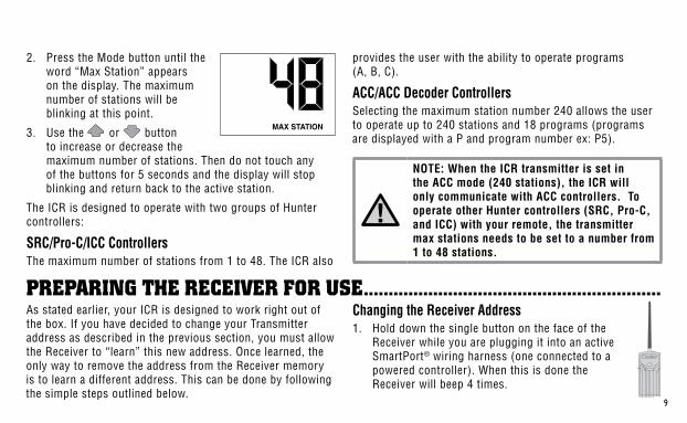
2.. Press.the.Mode.button.until.the.word.“Max.Station”.appears.on.the.display..The.maximum.number.of.stations.will.be..blinking.at.this.point.
3.. Use.the. .or. .button.to.increase.or.decrease.the.maximum.number.of.stations..Then.do.not.touch.any.of.the.buttons.for.5.seconds.and.the.display.will.stop.blinking.and.return.back.to.the.active.station.
The.ICR.is.designed.to.operate.with.two.groups.of.Hunter.controllers:
SRC/Pro-C/ICC ControllersThe.maximum.number.of.stations.from.1.to.48..The.ICR.also.
provides.the.user.with.the.ability.to.operate.programs..(A,.B,.C).
ACC/ACC Decoder ControllersSelecting.the.maximum.station.number.240.allows.the.user.to.operate.up.to.240.stations.and.18.programs.(programs.are.displayed.with.a.P.and.program.number.ex:.P5).
preparing THe receiver for use ............................................................As.stated.earlier,.your.ICR.is.designed.to.work.right.out.of.the.box..If.you.have.decided.to.change.your.Transmitter.address.as.described.in.the.previous.section,.you.must.allow.the.Receiver.to.“learn”.this.new.address..Once.learned,.the.only.way.to.remove.the.address.from.the.Receiver.memory.is.to.learn.a.different.address..This.can.be.done.by.following.the.simple.steps.outlined.below.
Changing the Receiver Address1.. Hold.down.the.single.button.on.the.face.of.the.
Receiver.while.you.are.plugging.it.into.an.active.SmartPort®.wiring.harness.(one.connected.to.a.powered.controller)..When.this.is.done.the..Receiver.will.beep.4.times.
NOTE: When the ICR transmitter is set in the ACC mode (240 stations), the ICR will only communicate with ACC controllers. To operate other Hunter controllers (SRC, Pro-C, and ICC) with your remote, the transmitter max stations needs to be set to a number from 1 to 48 stations.

�0
To remotely activate a station or program:1.. Plug.your.Receiver.into.an.active.SmartPort®.wiring.
harness.(one.attached.to.a.powered.controller).and.wait.for.2.beeps.indicating.the.Receiver.is.ready..
2.. If.your.Transmitter.is.not.on.(no.display),.press.any.button.for.at.least.1.second.and.release..The.Transmitter.will.display.the.active.station.
3.. Use.the. .or. .buttons.to.display.the.station.or.program.(A,B,.or.C).you.would.like.to.start.
4.. Momentarily.press.the.“ON”.button.to.start.the.station.or.program..The.Transmitter.will.display.the.word.“TRANSMIT”.
and.will.flash.for.about.4.seconds.indicating.that.it.is.sending.the.command.to.the.Receiver..If.you.are.near.the.Receiver,.you.will.hear.it.beep.2.times,.indicating.that.it.has.received.the.command.
5.. Press.the.“OFF”.button.at.any.time.to.turn.off.the.station.or.program..The.display.will.again.read.“TRANSMIT”.and.flash,.and.the.Receiver.will.again.beep.twice..The.ICR.is.designed.to.turn.one.station.on.at.a.time..Therefore,.turning.a.station.on.while.another.is.already.on.will.cause.the.first.station.to.turn.off.
6.. If.one.of.the.programs.(A,B,.C.or.P1.through.P18).is.selected,.all.stations.in.the.selected.program.will.run.sequentially.for.the.run.time.programmed.in.the.controller.
acTivaTing a sTaTion WiTH THe icr remoTe sysTem ......................
2.. After.the.Receiver.starts.to.beep,.release.the.button.
3.. Press.either.the.“ON”.or.“OFF”.button.on.your.transmit-ter.
4.. The.Receiver.will.beep.4.additional.times.indicating.that.it.has.learned.the.new.Transmitter.address.and.will.respond.only.to.it.from.this.point.on.
The.ICR.system.will.allow.you.to.remotely.turn.on.and.off.any.station.on.your.Hunter.controller.with.the.press.of.a.button..Once.on,.the.station.will.run.for.the.run.time.you.have.designated.in.the.ICR.transmitter.
��
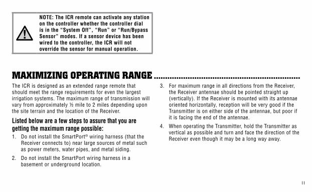
NOTE: The ICR remote can activate any station on the controller whether the controller dial is in the “System Off”, “Run” or “Run/Bypass Sensor” modes. If a sensor device has been wired to the controller, the ICR will not override the sensor for manual operation.
The.ICR.is.designed.as.an.extended.range.remote.that.should.meet.the.range.requirements.for.even.the.largest.irrigation.systems..The.maximum.range.of.transmission.will.vary.from.approximately.½.mile.to.2.miles.depending.upon.the.site.terrain.and.the.location.of.the.Receiver.
Listed below are a few steps to assure that you are getting the maximum range possible:1.. Do.not.install.the.SmartPort®.wiring.harness.(that.the.
Receiver.connects.to).near.large.sources.of.metal.such.as.power.meters,.water.pipes,.and.metal.siding.
2.. Do.not.install.the.SmartPort.wiring.harness.in.a.basement.or.underground.location.
3.. For.maximum.range.in.all.directions.from.the.Receiver,.the.Receiver.antennae.should.be.pointed.straight.up.(vertically)..If.the.Receiver.is.mounted.with.its.antennae.oriented.horizontally,.reception.will.be.very.good.if.the.Transmitter.is.on.either.side.of.the.antennae,.but.poor.if.it.is.facing.the.end.of.the.antennae.
4.. When.operating.the.Transmitter,.hold.the.Transmitter.as.vertical.as.possible.and.turn.and.face.the.direction.of.the.Receiver.even.though.it.may.be.a.long.way.away.
maximizing operaTing range .................................................................

��
TroublesHooTing guide .............................................................................PROBLEM CAUSES SOLUTIONSTransmitter.is.blank. Transmitter.is.Off..
.Battery.is.dead.
Press.any.button.for.1.second...Replace.battery.
Can’t.access.all.the.desired.stations.on.the.transmitter.
Maximum.station.number.is..set.wrong.
See.“Setting.the.Maximum.Station.stations.Number”
Receiver.doesn’t.beep.two.times.after.plugging.it.into.the.SmartPort®.
SmartPort.is.not.connected.properly...Controller.has.no.power.
Recheck.the.SmartPort.installation...Check.controller.power.
Receiver.beeps.twice.after.plugging.it.in,.but.won’t.respond.to.the.transmitter.
Receiver.and.Transmitter.addresses.don’t.match.
Relearn.address.at.Receiver.
Transmitter.display.stays.on. Transmitter.will.turn.off.automatically.
Wait.approximately.2.minutes.without.pressing.any.buttons..Transmitter.will.“fall.asleep.”
��
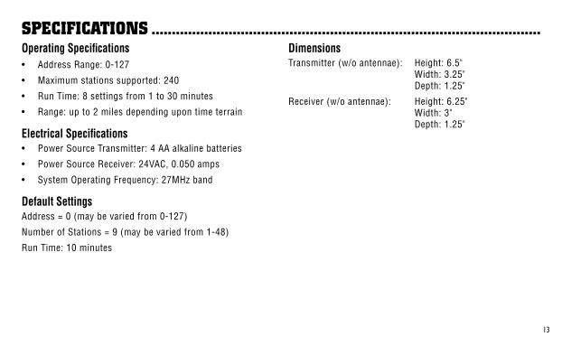
specificaTions ................................................................................................Operating Specifications•. Address.Range:.0-127
•. Maximum.stations.supported:.240
•. Run.Time:.8.settings.from.1.to.30.minutes
•. Range:.up.to.2.miles.depending.upon.time.terrain
Electrical Specifications•. Power.Source.Transmitter:.4.AA.alkaline.batteries
•. Power.Source.Receiver:.24VAC,.0.050.amps
•. System.Operating.Frequency:.27MHz.band
Default SettingsAddress.=.0.(may.be.varied.from.0-127)
Number.of.Stations.=.9.(may.be.varied.from.1-48)
Run.Time:.10.minutes
DimensionsTransmitter.(w/o.antennae):. Height:.6.5".
. Width:.3.25".
. Depth:.1.25"
Receiver.(w/o.antennae):. Height:.6.25".. . . Width:.3".. . . Depth:.1.25"


��
presenTación del producTo ....................................................................Por.fin.hay.un.sistema.de.mando.a.distancia.fiable.y.accesible,.diseñado.teniendo.en.mente.las.necesidades.del.contratista.de.la.industria.de.riego.comercial..La.sociedad.Hunter.está.satisfecha.del.lanzamiento.del.ICR,.un.sistema.de.mando.a.distancia..Su.diseño.de.alta.resistencia.le.permite.funcionabilidad.similar.al.sistema.de.mando.tipo.SRR,.pero.con.una.capacidad.de.mayor.distancia.
Con.el.ICR.no.existe.la.necesidad.de.caminar.de.ida.y.regreso.al.programador.para.llevar.a.cabo.operaciones.de.riego.cuando.esté.haciendo.labores.de.mantenimiento.o.reparación.de.su.sistema.de.riego..Asimismo,.las.actividades.de.preparación.para.el.invierno.pueden.implementarse.rápida.y.fácilmente.con.un.trabajador.en.lugar.de.dos.
El.ICR.está.diseñado.para.ser.de.alta.dureza.e.impermeable..Su.gran.pantalla.LCD.y.su.diseño.de.teclas.de.presión.lo.hacen.fácil.de.operar..Lo.mejor.de.todo.es.que,.con.un.rango.de.operación.de.½.hasta.2.millas,.dependiendo.del.terreno,.usted.podrá.ejecutar.operación.con.control.de.mando,.aún.en.los.sistemas.de.riego.más.extensos.
Las.siguientes.indicaciones.le.proporcionarán.la.información.necesaria.para.instalar,.modificar.y.operar.su.sistema. .operativo.ICR.

��
componenTes del icr ..................................................................................
ICR
OFF ONMODE
®
A
2
3
4
1
B D
C
5
7
86
9

��
Esta.sección.le.proporcionará.un.breve.resumen.ejecutivo.respecto.a.los.componentes.del.ICR..Cada.componente.será.comentado.con.mayor.detalle.posteriormente,.asimismo,.la.presente.sección.le.será.útil.para.familiarizarse.con.las.diferentes.opciones.disponibles.del.producto.
A – Emisor1.. Cuerpo del Emisor.–.El.Emisor.ICR.está.diseñado.para.
soportar.la.suciedad.y.es.impermeable.
2.. Pantalla tipo LCD.–.Grande,.fácil.de.leer
3.. Tecleado de Mando a Distancia de Presión.–.Fácil.de.operar.
4.. Antenas Externas.–.Flexibles,.de.goma.desmontable.para.un.radio.de.acción.óptimo.
5.. Compartimiento de las Pilas.–.El.diseño.ICR.es.fácil.de.operar.mediante.cuatro.pilas.alcalinas.
6.. Porta- Cinturón.–.Le.proporciona,.en.todo.momento,.un.conveniente.acceso.al.emisor.
B – Receptor7.. Cuerpo del Receptor.–.De.alta.resistencia,.con.diseño.
impermeable.
8.. Botón de Acceso.–.Le.permite.un.fácil.acceso.al.receptor.para.comunicarse.con.el.emisor.
9.. Antenas Externas.–.Flexibles,.desmontables.para.un.radio.de.acción.óptimo.
C – SmartPort®
D – Caja

��
A.fin.de.poder.utilizar.el.sistema.de.mando.a.distancia.ICR,.su.programador.Hunter.está.equipado.con.un.arnés.de.cableado.SmartPort..Dicho.cableado.de.arnés.le.proporciona.una.comunicación.al.puerto.a.donde.se.conecta.el.receptor.ICR..El.SmartPort.puede.conectarse.a.los.programadores.SRC,.Pro-C.y.al.programador.ICC..Para.su.conveniencia,.su.sistema.de.mando.a.distancia.ICR.incluye.un.arnés.de.cableado.tipo.SmartPort..La.localización.típica.del.SmartPort.es.de.12".abajo.del.programador..El.procedimiento.que.se.recomienda.para.la.instalación.respectiva.es.como.sigue:
1.. Instale.un.adaptador.de.“T”.de.rosca.hembra.de.½".en.el.compartimiento.del.cableado.aproximadamente.12".abajo.del.programador.
2.. Pase.los.cables.rojo,.blanco.y.azul.del.SmartPort.por.la.base.de.la.“T”.hacia.el.compartimiento.del.cableado.como.se.indica.en.la.ilustración.
conexión de cableado del programador smartport® ....................
insTalación del arnés de cableado smartport ................................
NOTA: El arnés puede en el exterior estableciendo un conducto a través de la pared externa, y posteriormente, llevar a cabo la instalación adecuada).
1/2" Rosca
Al Programador
Pre-ensamblado Ensamblado
��
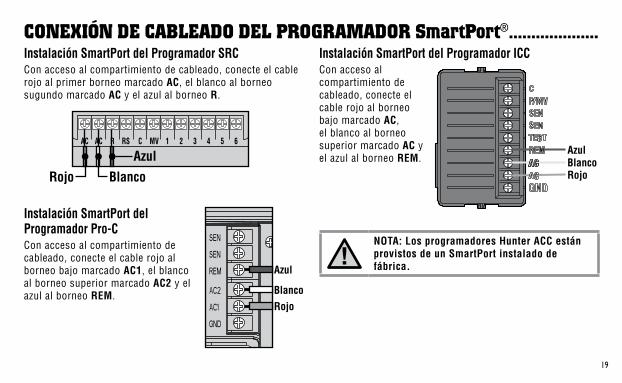
Instalación SmartPort del Programador SRCCon.acceso.al.compartimiento.de.cableado,.conecte.el.cable.rojo.al.primer.borneo.marcado.AC,.el.blanco.al.borneo..sugundo.marcado.AC.y.el.azul.al.borneo.R.
Instalación SmartPort del Programador Pro-CCon.acceso.al.compartimiento.de.cableado,.conecte.el.cable.rojo.al.borneo.bajo.marcado.AC1,.el.blanco.al.borneo.superior.marcado.AC2.y.el.azul.al.borneo.REM.
Instalación SmartPort del Programador ICCCon.acceso.al.compartimiento.de.cableado,.conecte.el.cable.rojo.al.borneo.bajo.marcado.AC,.el.blanco.al.borneo.superior.marcado.AC.y.el.azul.al.borneo.REM.
conexión de cableado del programador smartport® ....................
NOTA: Los programadores Hunter ACC están provistos de un SmartPort instalado de fábrica.
Rojo
Azul
Blanco
Power Module
AzulBlancoRojo
AC AC R RS C MV 1 2 3 4 5 6
Blanco
Azul
Rojo
�0
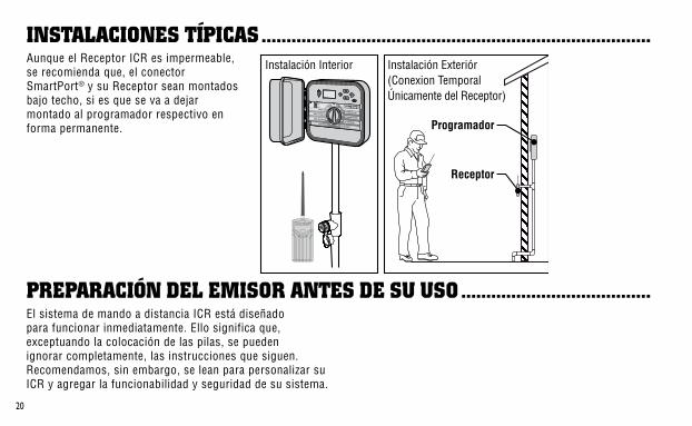
Aunque.el.Receptor.ICR.es.impermeable,.se.recomienda.que,.el.conector.SmartPort®.y.su.Receptor.sean.montados.bajo.techo,.si.es.que.se.va.a.dejar.montado.al.programador.respectivo.en.forma.permanente.
El.sistema.de.mando.a.distancia.ICR.está.diseñado.para.funcionar.inmediatamente..Ello.significa.que,.exceptuando.la.colocación.de.las.pilas,.se.pueden.ignorar.completamente,.las.instrucciones.que.siguen..Recomendamos,.sin.embargo,.se.lean.para.personalizar.su.ICR.y.agregar.la.funcionabilidad.y.seguridad.de.su.sistema.
insTalaciones Típicas ..............................................................................
preparación del emisor anTes de su uso ......................................
Programador
Receptor
Instalación Exteriór(Conexion TemporalÚnicamente del Receptor)
Instalación Interior

��
Su.emisor.ICR.funciona.con.cuatro.pilas.alcalinas.de.clase.AA..Para.instalar.las.pilas,.desplace.los.dos.tornillos.que.sujetan.el.compartimiento.posterior.del.emisor..Introduzca.las.pilas.en.dicho.compartimiento.e.instale.nuevamente.la.tapa.posterior..Concluyendo.lo.anterior,.su.emisor.está.listo.para.operar.
Una.vez.que.el.ICR.haya.sido.activado,.usted.cuenta.con.la.habilidad.de.ajustar.el.ciclo.de.riego.que.desea.en.una.estación.determinada..Lo.anterior,.no.afecta.el.ciclo.de.riego.que.haya.programado.en.su.programador..Dicho.ajuste.se.lleva.a.cabo.con.el.emisor.según.se.indica.a.continuación.
Cambios al Tiempos de Riego1.. Si.el.emisor.no.está.alimentado.OFF.(ausencia.en.
pantalla),.colocarlo.bajo.tensión.pulsando.cualquier.tecla.durante.al.menos.1.segundo,.entonces,.suelte.la.tecla..El.emisor.iluminará.la.pantalla.y.se.activará.la.estación.correspondiente.
2.. Presione.la.tecla.“Mode”,.hasta.que.aparezcan.las.palabras.“Run.Time”..(La.duración.de.falla.es.de.10.segundos)..A.continuación.la.pantalla.está.intermitente..Seña-lamos.que,.si.se.esperan.más.de.5.segundos.sin.solicitar.ninguna.tecla,.el.emisor.visualiza.de.nuevo.la.estación.activa.
3.. Utilizar.las.teclas. .y. .para.seleccionar.uno.de.los.8.ajustes.de.la.duración.del.riego.que.van.de.1.a.90.minutos..No.pulsar.ninguna.tecla.durante.al.menos.5.segundos,.la.pantalla.deja.de.estar.intermitente.y.vuelve.a.la.indicación.de.la.estación.activa.
colocación de la pila del emisor ......................................................
cambio del Tiempo del ciclo de riego ..............................................
��
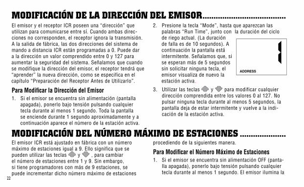
El.emisor.y.el.receptor.ICR.poseen.una.“dirección”.que.utilizan.para.comunicarse.entre.sí..Cuando.ambas.direc-ciones.no.corresponden,.el.receptor.ignora.la.transmisión..A.la.salida.de.fábrica,.las.dos.direcciones.del.sistema.de.mando.a.distancia.ICR.están.programadas.a.0..Puede.dar.a.la.dirección.un.valor.comprendido.entre.0.y.127.para.aumentar.la.seguridad.del.sistema..Señalamos.que.cuando.se.modifique.la.dirección.del.emisor,.el.receptor.tendrá.que.“aprender”.la.nueva.dirección,.como.se.especifica.en.el.capítulo.“Preparación.del.Receptor.Antes.de.Utilizarlo”.
Para Modificar la Dirección del Emisor1.. Si.el.emisor.se.encuentra.sin.alimentación.(pantalla.
apagada),.ponerlo.bajo.tensión.pulsando.cualquier.tecla.durante.al.menos.1.segundo..Toda.la.pantalla.se.enciende.durante.1.segundo.aproximadamente.y.a.continuación.aparece.el.número.de.la.estación.activa.
2.. Presione.la.tecla.“Mode”,.hasta.que.aparezcan.las.palabras.“Run.Time”,.junto.con..la.duración.del.ciclo.de.riego.actual..(La.duración.de.falla.es.de.10.segundos)..A.continuación.la.pantalla.está.intermitente..Señalamos.que,.si.se.esperan.más.de.5.segundos.sin.solicitar.ninguna.tecla,.el.emisor.visualiza.de.nuevo.la.estación.activa..
3.. Utilizar.las.teclas. .y. .para.modificar.cualquier.dirección.comprendida.entre.los.valores.0.al.127..No.pulsar.ninguna.tecla.durante.al.menos.5.segundos,.la.pantalla.deja.de.estar.intermitente.y.vuelve.a.la.indi-cación.de.la.estación.activa.
El.emisor.ICR.está.ajustado.en.fábrica.con.un.número.máximo.de.estaciones.igual.a.9..Ello.significa.que.se.pueden.utilizar.las.teclas. .y. .,.para.cambiar.el.número.de.estaciones.entre.1.y.9..Sin.embargo,.si.tiene.programadores.con.más.de.9.estaciones,.se.puede.incrementar.dicho.número.máximo.de.estaciones.
procediendo.de.la.siguientes.manera.
Para Modificar el Número Máximo de Estaciones1.. Si.el.emisor.se.encuentra.sin.alimentación.OFF.(panta-
lla.apagada),.ponerlo.bajo.tensión.pulsando.cualquier.tecla.durante.al.menos.1.segundo..El.emisor.ilumina.la..
modificación de la dirección del emisor ......................................
modificación del número máximo de esTaciones .....................

��
estación.activa.
2.. Presione.la.tecla.“Mode”,.hasta.que.aparezcan.las.palabras.“Max..Station”.en.la.pantalla..A.continuación.aparece.en.la.pantalla,.en.forma.intermitente,.el.número.máximo.de.estacio-nes..Señalamos.que,.si.se.esperan.más.de.5.segundos.sin.solicitar.ninguna.tecla,.el.emisor.visualiza.de.nuevo.la.estación.activa.
3.. Utilizar.las.teclas. .y. .para.incrementar.o.reducir,.el.número.máximo.de.estaciones..Posteriormente,.no.pulsar.ninguna.tecla.durante.al.menos.5.segundos,.la.pantalla.deja.de.estar.intermitente.y.vuelve.a.la.indicación.de.la.estación.activa.
El.ICR.está.diseñado.para.que.funcione.con.dos.grupos.de.programadores.Hunter:
Programadores SRC/Pro-C/ICCEl.máximo.número.de.estaciones.de.1.a.48..El.ICR.proporciona.además.la.capacidad.de.poner.programas.en.funcionamiento.(A,.B,.C).
Programadores ACC/ACC99D de decodificadores La.selección.del.máximo.número.de.estaciones,.240,.permite.poner.en.funcionamiento.hasta.240.estaciones.y.18.programas.(los.programas.se.muestran.con.una.P.y.el.número.de.programa,.ej.:.P5).
Como.ya.hemos.señalado,.su.sistema.de.mando.a.distancia.ICR,.está.listo.para.su.empleo..Si.ha.cambiado.la.dirección.de.su.emisor.del.modo.anteriormente.descrito,.el.receptor.respectivo.tiene.que.“aprender”.la.nueva.dirección..Una.vez.
que.el.receptor.haya.aprendido.la.nueva.dirección,.la.única.manera.de.borrarla.consistirá.en.enseñarle.otra.actuando.de.la.manera.siguiente:.
preparación del recepTor anTes de su uso ..........................
NOTA: Cuando el mando a distancia ICR transmite en modo ACC (para 240 estaciones) sólo podrá comunicarse con modelos de programadores ACC. Para utilizar programadores estánderes de Hunter (SRC, Pro-C y ICC) se deberá utilizar el modo de transmisión estándar (programado para funcionar de 1 a 48 estaciones).

��
Modificación de la Dirección del Receptor1.. Mantener.hundida.la.única.tecla.situada.sobre.la.cara.
delantera.del.receptor.mientras.que.se.conecta.a.un.conjunto.de.cables.bajo.tensión.de.un.SmartPort®.(el.programador.bajo.tensión)..Cuanto.esto.sucede,.el.Receptor.emite.cuatro.bips.acústicos.
2.. Soltar.el.botón.en.cuanto.se.oiga.el.primer.bip.
3.. Pulsar.la.tecla.“ON”.o.la.tecla.“OFF”.de.su.emisor.
4.. El.Receptor.produce.4.bips.acústicos.para.indicar.que.ha.aprendido.la.nueva.dirección.del.emisor.y.que.ya.no.contestará.a.otra.distinta.
acTivación de una esTación por medio del sisTema de mando a disTancia icr ...............................................El.sistema.de.mando.a.distancia.ICR.permite.arrancar.o.parar.cualquier.estación.de.su.programador.Hunter.presionando.una.única.tecla..Una.vez.que.se.ha.activado.una.estación,.la.misma.funcionará.durante.el.ciclo.de.riego.programado.por.medio.del.emisor.ICR.
Para Activar a distancia una estación o un programa, hay que proceder de la manera siguiente:1.. Conectar.su.Receptor.a.un.Smart-
Port®.activo.(el.programador.bajo.tensión).y.espere.a.que.el.mismo.emita.2.bips.acústicos.indicando.que.el.Receptor.está.listo.
2.. Si.el.emisor.no.está.alimentado.(sin.pantalla),.pulsar.cualquier.
tecla.durante.al.menos.1.segundo.y.a.continuación.aparece.el.número.de.la.estación.activa.
3.. Utilizar.las.teclas. .y. .para.visualizar.la.estación.o.el.programa.(A,.B,.o.C).que.desea.activar.
4.. Pulsar.la.tecla.“ON”.para.arrancar.la.estación.o.programa..Sobre.la.pantalla.del.emisor.aparecen.las.pal-abras.“ON”.y.“TRANSMIT”.y.están.intermitentes.durante.aproximadamente.4.segundos.para.indicar.que.se.ha.transmitido.la.orden.al.receptor..El.Receptor.emite.2.bis.acústicos.para.indicar.que.ha.recibido.la.orden.
5.. Pulsar.la.tecla.“OFF”.en.cualquier.momento.a.fin.de.parar.la.estación.o.programa.que.están.funcionando..Aparecen.las.palabras.“OFF”.y.“TRANSMIT”.en.forma.intermitente,.y.el.Receptor.emite.de.nuevo.2.bips.
��
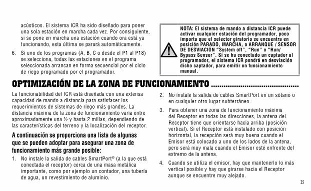
2.. No.instale.la.salida.de.cables.SmartPort.en.un.sótano.o.en.cualquier.otro.lugar.subterráneo.
3.. Para.obtener.una.zona.de.funcionamiento.máxima.del.Receptor.en.todas.las.direcciones,.la.antena.del.Receptor.tiene.que.orientarse.hacia.arriba.(posición.vertical)..Si.el.Receptor.está.instalado.con.posición.horizontal,.la.recepción.será.muy.buena.cuando.el.Emisor.está.colocado.a.uno.de.los.lados.de.la.antena,.pero.será.muy.mala.cuando.el.Emisor.esté.enfrente.del.extremo.de.la.antena.
4.. Cuando.se.utiliza.el.emisor,.hay.que.mantenerlo.lo.más.vertical.posible.y.hay.que.girarse.hacia.el.Receptor.aunque.se.encuentre.muy.alejado.
opTimización de la zona de funcionamienTo ..........................................
acústicos..El.sistema.ICR.ha.sido.diseñado.para.poner.una.sola.estación.en.marcha.cada.vez..Por.consiguiente,.si.se.pone.en.marcha.una.estación.cuando.ora.está.ya.funcionando,.esta.última.se.parará.automáticamente.
6.. Si.uno.de.los.programas.(A,.B,.C.o.desde.el.P1.al.P18).se.selecciona,.todas.las.estaciones.en.el.programa.seleccionada.arrancan.en.forma.secuencial.por.el.ciclo.de.riego.programado.por.el.programador.
NOTA: El sistema de mando a distancia ICR puede activar cualquier estación del programador, poco importa que el selector giratorio se encuentra en posición PARADO, MARCHA, o ARRANQUE / SENSOR DE DESVIACIÓN “System off”, “Run” o “Run/Bypass Sensor”. Si se ha conectado un captador al programador, el sistema ICR pondrá en desviación dicho captador, para emitir un funcionamiento manual.
La.funcionabilidad.del.ICR.está.diseñada.con.una.extensa.capacidad.de.mando.a.distancia.para.satisfacer.los.requerimientos.de.sistemas.de.riego.más.grandes..La.distancia.máxima.de.la.zona.de.funcionamiento.varía.entre.aproximadamente.una.½.y.hasta.2.millas,.dependiendo.de.las.características.del.terreno.y.la.localización.del.receptor.
A continuación se proporciona una lista de algunas que se pueden adoptar para asegurar una zona de funcionamiento más grande posible:1.. No.instale.la.salida.de.cables.SmartPort®.(a.la.que.está.
conectada.el.receptor).cerca.de.una.masa.metálica.importante,.como.por.ejemplo.un.contador,.una.tubería.de.agua,.un.revestimiento.de.aluminio.
��
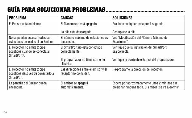
guía para solucionar problemas .........................................................PROBLEMA CAUSAS SOLUCIONESEl.Emisor.está.en.blanco. El.Transmisor.está.apagado..
.La.pila.está.descargada.
Presione.cualquier.tecla.por.1.segundo...Reemplace.la.pila.
No.se.pueden.accesar.todas.las.estaciones.deseadas.el.en.Emisor.
El.número.máximo.de.estaciones.es.incorrecto.
Vea.“Modificación.del.Número.Máximo.de.Estaciones”.
El.Receptor.no.emite.2.bips.acústicos.cuando.se.conecta.al.SmartPort®.
El.SmartPort.no.está.conectado.correctamente...El.programador.no.tiene.corriente.eléctrica.
Verifique.que.la.instalación.del.SmartPort..sea.correcta...Verifique.la.corriente.eléctrica.del.programador.
El.Receptor.no.emite.2.bips.acústicos.después.de.conectarlo.al.SmartPort.
Las.direcciones.entre.el.emisor.y.el.receptor.no.coinciden.
Re-programe.la.dirección.del.receptor.
La.pantalla.del.Emisor.queda.encendida.
El.emisor.se.apagará.automáticamente.
Espere.por.aproximadamente.unos.2.minutos.sin.presionar.ninguna.tecla..El.emisor.“se.irá.a.dormir”.
��
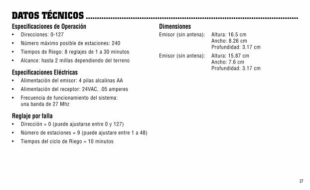
daTos Técnicos ...............................................................................................Especificaciones de Operación•. Direcciones:.0-127
•. Número.máximo.posible.de.estaciones:.240
•. Tiempos.de.Riego:.8.reglajes.de.1.a.30.minutos
•. Alcance:.hasta.2.millas.dependiendo.del.terreno
Especificaciones Eléctricas•. Alimentación.del.emisor:.4.pilas.alcalinas.AA
•. Alimentación.del.receptor:.24VAC,..05.amperes
•. Frecuencia.de.funcionamiento.del.sistema:. .una.banda.de.27.Mhz
Reglaje por falla•. Dirección.=.0.(puede.ajustarse.entre.0.y.127)
•. Número.de.estaciones.=.9.(puede.ajustare.entre.1.a.48).
•. Tiempos.del.ciclo.de.Riego.=.10.minutos
DimensionesEmisor.(sin.antena):. Altura:.16.5.cm.
. Ancho:.8.26.cm.
. Profundidad:.3.17.cm
Emisor.(sin.antena):. Altura:.15.87.cm.. . . Ancho:.7.6.cm.. . . Profundidad:.3.17.cm
fcc compliance noTice ...............................................................................This.device.does.not.require.an.FCC.License..The.ICR.Receiver.complies.with.the.limits.of.Part.15.of.the.FCC.Rules..The.Transmitter.complies.with.Part.95.Subpart.E.of.the.FCC.Rules..These.limits.are.designed.to.provide.reasonable.protection.against.harmful.interference.when.this.equipment.is.operated.in.a.commercial.environment.
Este.sistema.no.requiere.de.ninguna.licencia.de.la.FCC..El.receptor.ICR.cumple.con.los.límites.especificados.por.la.Sección.15.de.las.Reglas.correspondientes.de.la.FCC..El.emisor.cumple.con.los.estándares.definidos.en.la.parte.95,.sub-parte.E.de.las.Reglas.de.la.FCC..Estos.límites.se.han.designado.para.proporcionar.una.protección.razonable.contra.cualquier.interferencia.cuando.el.equipo.y.el.sistema.estén.funcionando.en.un.medio.ambiente.comercial.
Hunter Industries Incorporated • The Irrigation Innovators ©.2007.Hunter.Industries.Incorporated
1940 Diamond Street • San Marcos, California 92078 www.HunterIndustries.com • www.HunterRiego.com P/N.700914. LIT-357. 4/07