Institue of Rolling Stock Engineers, RCF Chapter
50
1
Transcript of Institue of Rolling Stock Engineers, RCF Chapter

1

2
Institue of Rolling Stock Engineers, RCF Chapter
Patron: Shri Ravinder Gupta, General Manager
Hony Office Bearers:
Shri R.K. Mangla, President
Shri Animesh Kumar Sinha, Genl. Secretary
3
Message from GM/RCF & Patron, IRSE/RCF Chapter
I am glad to know that 1" edition of IRSE RCF Chapter’s Technical Journal
’Charaiyvaiti is being published on occasion of IRSME Day’2021. Institute of Rolling
Stock Engineers being a vital element of Indian Railways has been taking various
initiatives to serve their organization in the best possible way. RCF, Kapurthala has
undertaken an exercise in mission mode for providing modern facilities along with
special focus on safety and comfort of the passengers.
This journal contains the technical information of various working aspects like Product
development, Plant maintenance, Design Department, Quality Assurance, IT
functionality, safety aspects and day- to-day developmental activities of RCF,
Kapurthala. It will not only be interesting and informative but will also serve as a
reliable source. I hope it provides the right spark in the members to disseminate
technical knowledge by contributing to this journal, which is an appropriate platform
for technical knowledge sharing in a structured manner.
I wish the Editor of the journal and the entire team for successful publication of the 1" Edition.
RCF/Kapurthala. Date: 12/02/2021
RAVINDER GUPTA

4
Message from PCME/RCF & President, IRSE/RCF Chapter
I am glad to know that Institute of Rolling Stock Engineers (IRSE), RCF
Chapter, is launching E- magazine on the occasion of IRSME Day 2021.
Indian Railways is one of the largest Rail network in the World and is the
backbone of the country's economy. The Institute of Rolling Stock
Engineers has always contributed to furtherance of modern knowledge
and latest technologies in the Rolling Stocks for improving the Reliability,
Safety and Speed.
I congratulate IRSE, RCF Chapter, for introducing the E-magazine which
will encourage the members in contributing and assimilating technical
knowledge and other valuable information.
I wish a great success to it.
Dated: 12.02.2021
Tele DOT +91-1822-228964 (0) Fax : +91-1822-227784
E-mail : cme@r cf.railnet.gov.in, [email protected], Website
://www.rcf.indianrailways.gov.in
5
Animesh Kumar Sinha
CME/IT
Charaiyvaiti (चरैवेति) is the technical journal of the Institute of Rolling
Stock Engineers, RCF Chapter. True to its name Charaiyvaiti which appears in the supreme philosophical oriental literature of Rigveda (Aitraya Brahman) epitomizes continuous motion and movement as the means to true salvation and attaining the supreme truth. The community of Institute of Rolling Stock Engineers has kept the wheels moving over atleast 200 years since the start of steam loco hauled passenger trains and progressively fuelled by the pursuit of new technologies amidst great challenges. Rolling Stock Technology forms the lifeline of transportation across the globe and has singular importance in the economy, transportation and development of any country.
Our brethren of Rolling Stock community have held the flag high and came up
with several technological innovations for serving the cause of the nation. Be it converting COVID 19 coaches or VP on LHB platform for expeditious goods movement during COVID 19 period, double decker and economy variant of AC 3 tier and exceeding production targets . and scripting a new history.
This journal shall serve the purpose to act as a repository of various technical
articles which have contributed in great technical achievements as well as those in conceptual stage having the potential to bring quantum improvements.
Keep the wheels rolling.
6
Index S.No. Title Author Page
No.
1. Railways- A Travel across 2600 years
Animesh Kumar Sinha, CME/IT 7-16
2. Recent Rolling Stock Design Projects of RCF
Manish Bhimte, ex-CDE 17-21
3. Air Spring Design being used in passenger coaches of Indian Railways
Kamal Kumar, Dy CME/D-I 22-30
4. An overview of Machinery & Plant Maintenance activities at RCF
Vineet Singhal, CPE 31-45
5. EN 45545- Fire Protection of Railway vehicle.
Abhey Priya, Dy CME/D-II 46-50

7
Article Title & Index
1. Railways – A Travel across 2600 years - by Sh Animesh Sinha, CME/IT
1.1 Common Perception
1.2 Reality
Railway Operation started much before the invention of Railway Engine
On Rutways
1.3 Diolkos
Salient Features of Rutway
In Operation till 1st Century AD
Laying of 1st Railways in various parts of India
Expansion of Railway Network under private Companies
Taking over of Private Railway Companies
Formation of Railway Board and other Regulatory Units
Re-organisation of IR 1951 onwards
Key Statistics of Indian Railways Year Book 2018-19
Progress of Coaching PUs
8
Animesh Kumar Sinha, CME/IT
Railways – A Travel across 2600 years
Synopsis: Railways, in true sense, emerged much before the invention of Railway
Engine. The earliest illustration of Railways emerges back to 600 BC in the form of
Rut Ways. It can be divided into several discrete periods defined by the principal
means of track material and motive power used. In 1803, steam Locomotive was
invented by Richard Trevithick, Indian Railways, which has modest beginning in 1853
has since then became the integral part of nation. Integration of Indian Railways from
erstwhile British Railways into a single entity, all started with formation of Railway
Board.
Despite beginning life as a by-product of British Colonial rule, Indian Railways has
emerged to define and shape the country over the course of time. Tracks that were
laid primarily for military requirements of the Raj and to fill the coffers of foreign
investors evolved to support the country itself, forming a staggeringly vast network,
becoming one of the most prestigious rail providers in the World.
1.1 Common Perception
1st Rail Engine was built by Mr. Richard Trevithick a British inventor and mining
Engineer in 1803.
1st Public Passenger Train started on 27.09.1825 from Darlington to Stockton
hauled by a Steam Engine Locomotion No.1 built by George Stephenson.
Incidentally, George Stephenson was the 1st Mechanical Engineer of the World.
1.2 Reality
Railway Operation started much before the invention of Railway Engine
On Rutways
Rail (Way) word is derived from RUT (WAY)
It can be natural and man made as well

9
Images of Rutways
1st Men made Rutway 600 BC
WHERE ?
CORINTH
1st Man made Rutway 600 BC
This Rutway joins 02 Sea –
Corinth Sea and Saronic Gulf
10
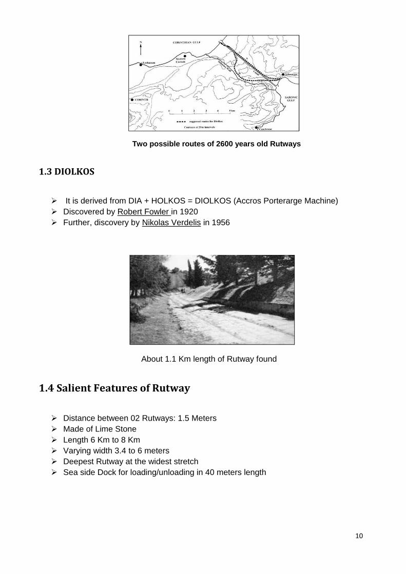
Two possible routes of 2600 years old Rutways
1.3 DIOLKOS
It is derived from DIA + HOLKOS = DIOLKOS (Accros Porterarge Machine)
Discovered by Robert Fowler in 1920
Further, discovery by Nikolas Verdelis in 1956
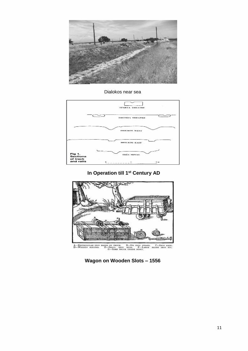
About 1.1 Km length of Rutway found
1.4 Salient Features of Rutway
Distance between 02 Rutways: 1.5 Meters
Made of Lime Stone
Length 6 Km to 8 Km
Varying width 3.4 to 6 meters
Deepest Rutway at the widest stretch
Sea side Dock for loading/unloading in 40 meters length
11
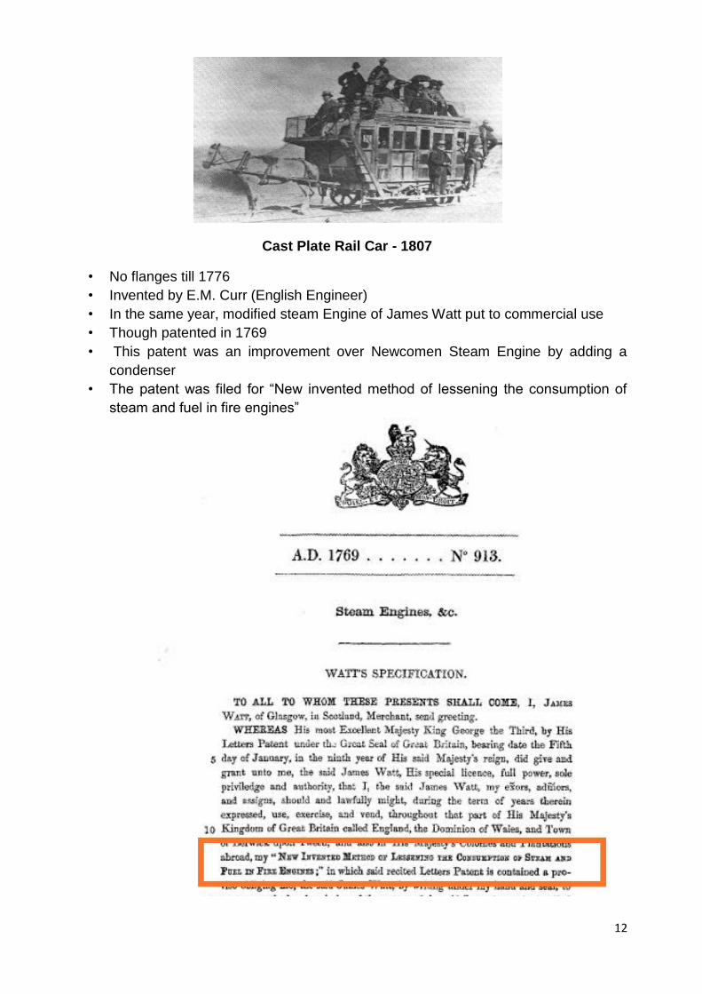
Dialokos near sea
In Operation till 1st Century AD
Wagon on Wooden Slots – 1556
12
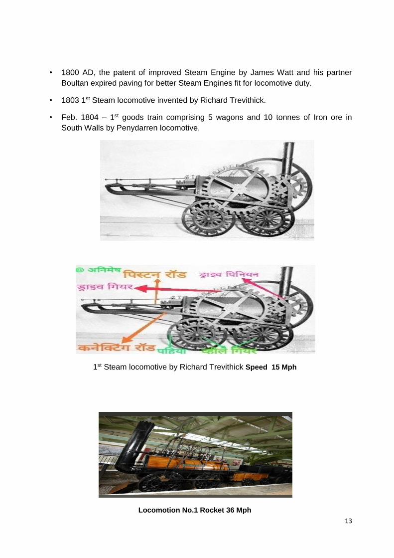
Cast Plate Rail Car - 1807
• No flanges till 1776
• Invented by E.M. Curr (English Engineer)
• In the same year, modified steam Engine of James Watt put to commercial use
• Though patented in 1769
• This patent was an improvement over Newcomen Steam Engine by adding a
condenser
• The patent was filed for “New invented method of lessening the consumption of
steam and fuel in fire engines”
13
• 1800 AD, the patent of improved Steam Engine by James Watt and his partner
Boultan expired paving for better Steam Engines fit for locomotive duty.
• 1803 1st Steam locomotive invented by Richard Trevithick.
• Feb. 1804 – 1st goods train comprising 5 wagons and 10 tonnes of Iron ore in
South Walls by Penydarren locomotive.
1st Steam locomotive by Richard Trevithick Speed 15 Mph
Locomotion No.1 Rocket 36 Mph
14
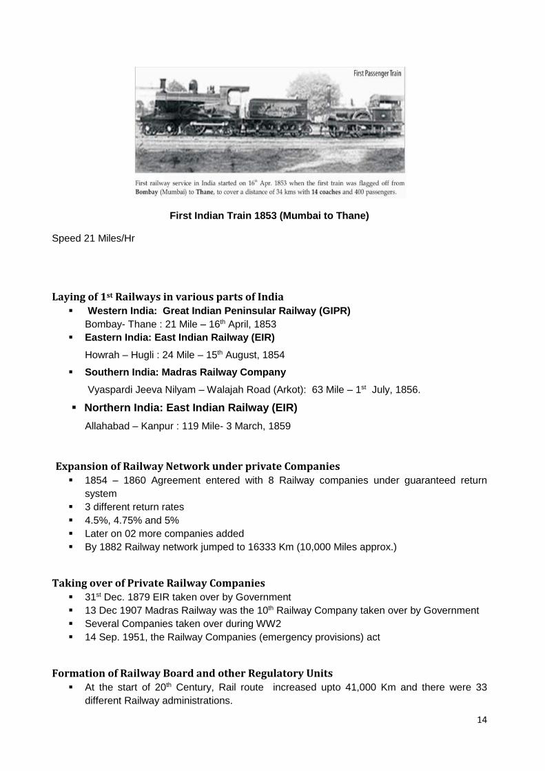
First Indian Train 1853 (Mumbai to Thane)
Speed 21 Miles/Hr
Laying of 1st Railways in various parts of India
Western India: Great Indian Peninsular Railway (GIPR)
Bombay- Thane : 21 Mile – 16th April, 1853
Eastern India: East Indian Railway (EIR)
Howrah – Hugli : 24 Mile – 15th August, 1854
Southern India: Madras Railway Company
Vyaspardi Jeeva Nilyam – Walajah Road (Arkot): 63 Mile – 1st July, 1856.
Northern India: East Indian Railway (EIR)
Allahabad – Kanpur : 119 Mile- 3 March, 1859
Expansion of Railway Network under private Companies 1854 – 1860 Agreement entered with 8 Railway companies under guaranteed return
system
3 different return rates
4.5%, 4.75% and 5%
Later on 02 more companies added
By 1882 Railway network jumped to 16333 Km (10,000 Miles approx.)
Taking over of Private Railway Companies 31st Dec. 1879 EIR taken over by Government
13 Dec 1907 Madras Railway was the 10th Railway Company taken over by Government
Several Companies taken over during WW2
14 Sep. 1951, the Railway Companies (emergency provisions) act
Formation of Railway Board and other Regulatory Units At the start of 20th Century, Rail route increased upto 41,000 Km and there were 33
different Railway administrations.
15
4 Government Railways
5 Erswhile Princely Railway
24 Private Railway Companies.
Administration & regulation by PWD
Formation of Railway Board and other Regulatory Units
1901 - Thomas Robertson was asked to submit report for re-organization.
1903 - Report submitted
1905 - Constitution of Railway Board.
1925 - Separate Railway Budget 1925 till 2016.
Length of Railway track in RKM 1882 - 16333RKM
1950 - 53596 RKM
1970-71 - 59790 RKM
2016-17 - 67637 RKM
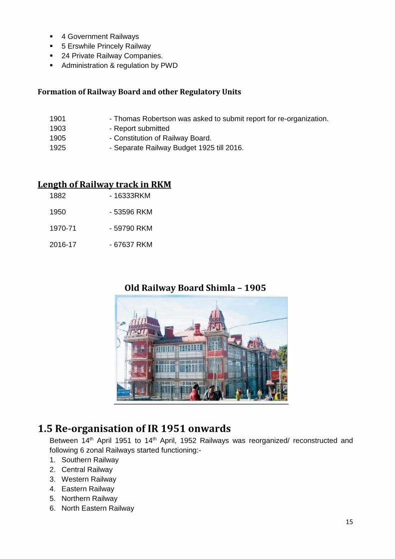
Old Railway Board Shimla – 1905
1.5 Re-organisation of IR 1951 onwards Between 14th April 1951 to 14th April, 1952 Railways was reorganized/ reconstructed and
following 6 zonal Railways started functioning:-
1. Southern Railway
2. Central Railway
3. Western Railway
4. Eastern Railway
5. Northern Railway
6. North Eastern Railway

16
With the time, these increased to 16 Zonal Railways and 1 Metro Railway.
Key Statistics of Indian Railways Year Book 2018-19
Progress of Coaching PUs
ICF, Chennai - 02.10.1955
RCF, Kapurthala - 17.08.1983/ 31.03.1988
MCF, Raibareli - Feb 2007/ Apr. 2011
The Bengaluru Complex (the then Rail Coach Factory) was in existence from 1947 as a
part of Aircraft Factory (currently Hindustan Aeronautics Limited). Initially, the division
was manufacturing Rolling Stock producing various models of Broad Gauge Coaches.
******
17
Article Title & Index
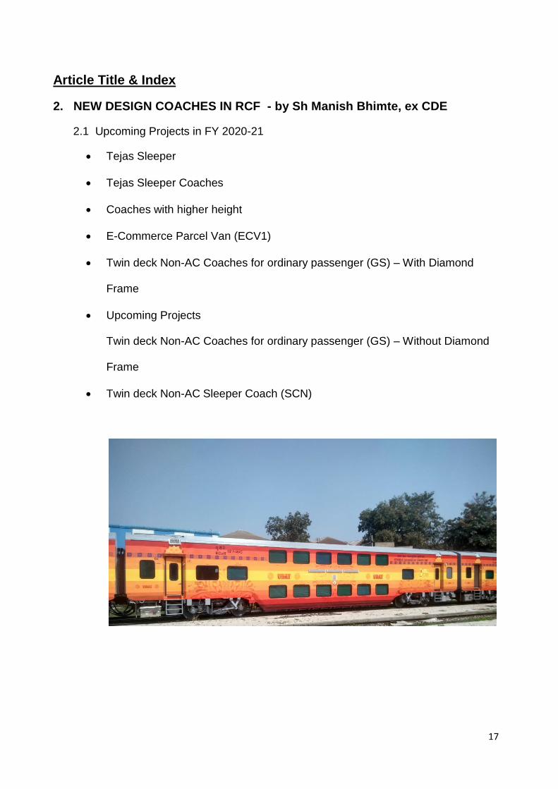
2. NEW DESIGN COACHES IN RCF - by Sh Manish Bhimte, ex CDE
2.1 Upcoming Projects in FY 2020-21
Tejas Sleeper
Tejas Sleeper Coaches
Coaches with higher height
E-Commerce Parcel Van (ECV1)
Twin deck Non-AC Coaches for ordinary passenger (GS) – With Diamond
Frame
Upcoming Projects
Twin deck Non-AC Coaches for ordinary passenger (GS) – Without Diamond
Frame
Twin deck Non-AC Sleeper Coach (SCN)

18
Manish Bhimte (ex CDE/RCF)
Upcoming Projects in FY 2020-21
Technical excellence in Coach Design at RCF (2020/21)/ Developmental endeavors
planned in FY 2020-21:
Synopsis: Design Team of RCF has been striving for excellence in Coach design, by
redesigning various Coach Variants already in operation under Indian Railways to
improve the travelling experience of passengers with enhanced safety features at
minimal costs, increasing passenger accommodation for fetching more earnings,
infotainment-cum-Passenger Information system, panoramic wider windows for lively
experience and design innovations specifically keeping in mind a feeling of roominess for
each passenger rather than cluttering of seats. Several new features are being worked
upon to transform the dynamics of commuting through Indian Railways at a standard
expense. TEJAS has been pioneered with features like Automatic entrance plug type
door, smoke detection, odor control etc.
2.1 Upcoming Projects Tejas Sleeper LWFAC – First AC Sleeper Coach
LWACCW – Second AC Sleeper Coach
LWACCN – Three Tier AC Sleeper Coach
LWCB – Hot Buffet Coach
19
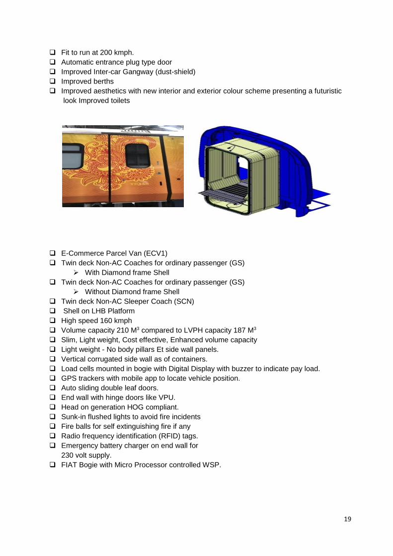
Fit to run at 200 kmph.
Automatic entrance plug type door
Improved Inter-car Gangway (dust-shield)
Improved berths
Improved aesthetics with new interior and exterior colour scheme presenting a futuristic
look Improved toilets
E-Commerce Parcel Van (ECV1)
Twin deck Non-AC Coaches for ordinary passenger (GS)
With Diamond frame Shell
Twin deck Non-AC Coaches for ordinary passenger (GS)
Without Diamond frame Shell
Twin deck Non-AC Sleeper Coach (SCN)
Shell on LHB Platform
High speed 160 kmph
Volume capacity 210 M3 compared to LVPH capacity 187 M3
Slim, Light weight, Cost effective, Enhanced volume capacity
Light weight - No body pillars Et side wall panels.
Vertical corrugated side wall as of containers.
Load cells mounted in bogie with Digital Display with buzzer to indicate pay load.
GPS trackers with mobile app to locate vehicle position.
Auto sliding double leaf doors.
End wall with hinge doors like VPU.
Head on generation HOG compliant.
Sunk-in flushed lights to avoid fire incidents
Fire balls for self extinguishing fire if any
Radio frequency identification (RFID) tags.
Emergency battery charger on end wall for
230 volt supply.
FIAT Bogie with Micro Processor controlled WSP.
20
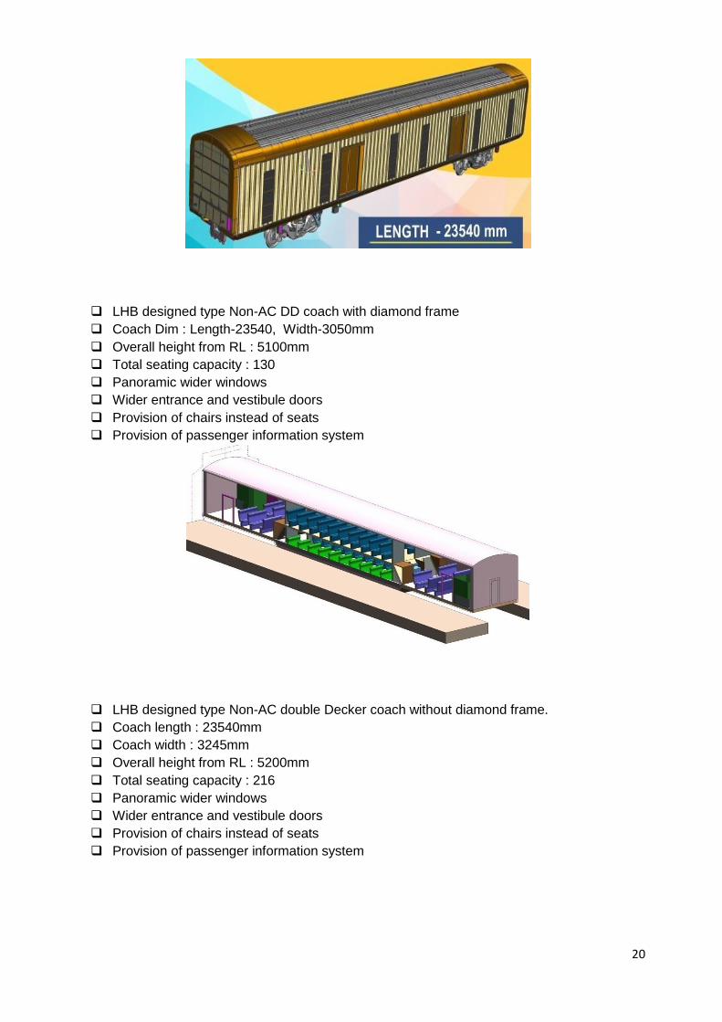
LHB designed type Non-AC DD coach with diamond frame
Coach Dim : Length-23540, Width-3050mm
Overall height from RL : 5100mm
Total seating capacity : 130
Panoramic wider windows
Wider entrance and vestibule doors
Provision of chairs instead of seats
Provision of passenger information system
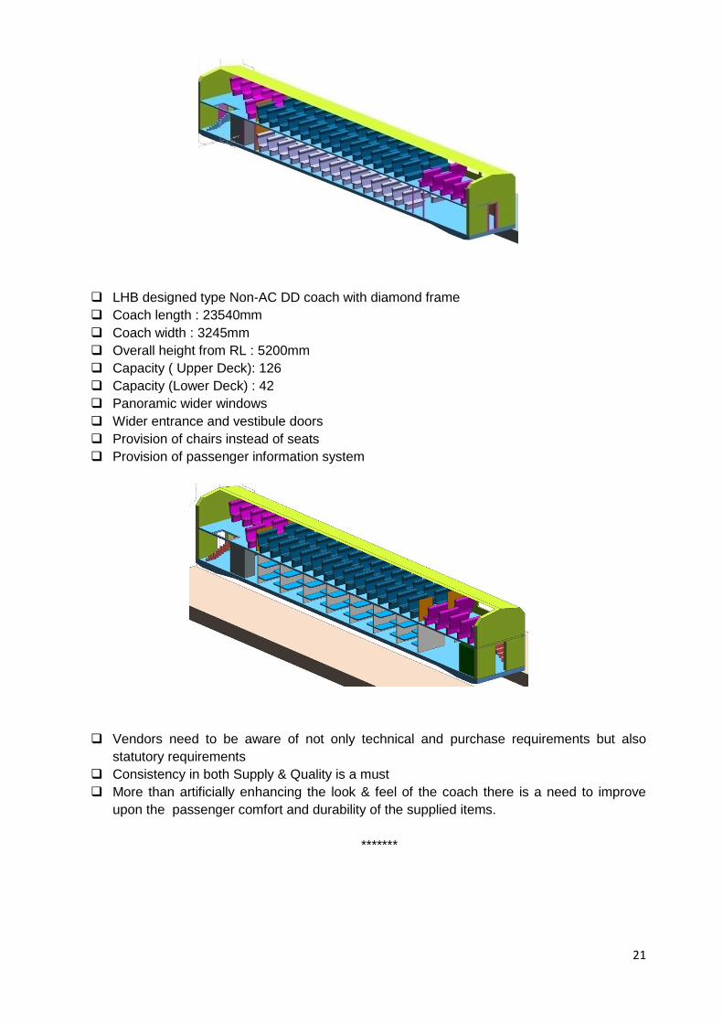
LHB designed type Non-AC double Decker coach without diamond frame.
Coach length : 23540mm
Coach width : 3245mm
Overall height from RL : 5200mm
Total seating capacity : 216
Panoramic wider windows
Wider entrance and vestibule doors
Provision of chairs instead of seats
Provision of passenger information system
21
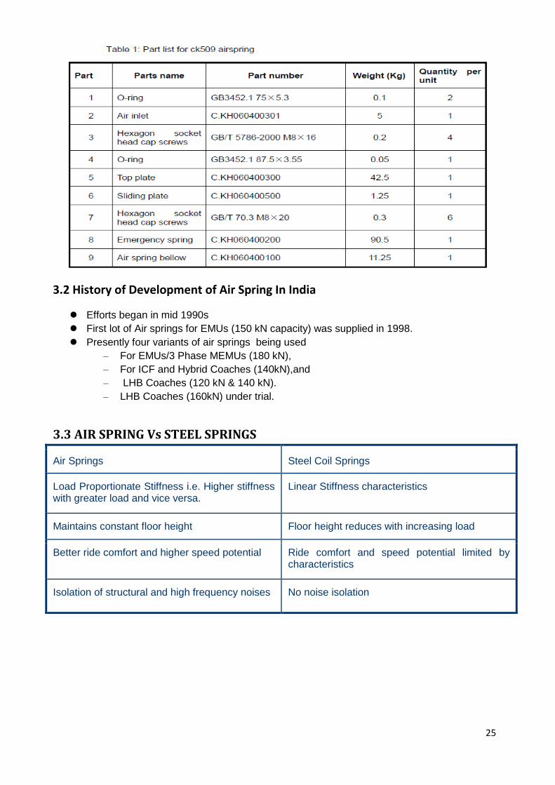
LHB designed type Non-AC DD coach with diamond frame
Coach length : 23540mm
Coach width : 3245mm
Overall height from RL : 5200mm
Capacity ( Upper Deck): 126
Capacity (Lower Deck) : 42
Panoramic wider windows
Wider entrance and vestibule doors
Provision of chairs instead of seats
Provision of passenger information system
Vendors need to be aware of not only technical and purchase requirements but also
statutory requirements
Consistency in both Supply & Quality is a must
More than artificially enhancing the look & feel of the coach there is a need to improve
upon the passenger comfort and durability of the supplied items.
*******

22
Article Title & Index
3. Air Spring Design Being Used In Passenger Coaches of Indian Railways
– by Shri Kamal Kumar, Dy CME/D-I
What Is an ‘Air Spring’?
Parts detail of Air Spring
History of Development of Air Spring In India
Air Spring Vs Steel Springs
Technical Requirement
Fiat Bogie With Air Spring In Secondary Suspension
Layout of Pneumatic Suspension Control Equipment
Air Spring Is A RDSO Controlled Category Ii Item
Approved Sources As Per RDSO Vendor Directory
Standardization Of 160 Kn Air Spring
Adoptation of Air Spring by RCF in ICF Type Coaches
Adoption of Air Spring by RCF in LHB Coaches
Air Springs – Maintenance Instructions
Air Springs – Advantages
Air Springs – Running Care
Air Spring Failures
Air Springs – Piping Layout

23
Kamal Kumar (Dy. CME/D-1)
AIR SPRING DESIGN BEING USED IN PASSENGER COACHES OF INDIAN
RAILWAYS
Synopsis: Air Spring design being used in Passenger Coaches of Indian Railways:
Air suspension, also called pneumatic suspension, uses the properties of air for the
cushioning effect. Air spring is a rubber bellow containing pressurized compressed air
with an emergency rubber spring providing various suspension characteristics to
maintain a constant buffer height irrespective of the loaded condition by varying the
pressure of air inside the spring.
Due to the Super Dense Crush Load, the bolster springs used to become solid which in
turn damages/ breaks the coil spring resulting in discomfort to the passenger. So, to
overcome the above problem, air spring has been introduced in the secondary
suspension resulting in enhancing the ride index (which remains the same in empty and
loaded condition), providing more comfort to passengers.
3. AIR SPRING DESIGN BEING USED IN PASSENGER COACHES OF INDIAN
RAILWAYS

24
3.1 What is an ‘Air Spring’?
‘Air spring’ refers to enclosed pressurized air in a predefined chamber made of rubber bellow with
an emergency rubber spring.
PARTS DETAIL OF AIR SPRING
25
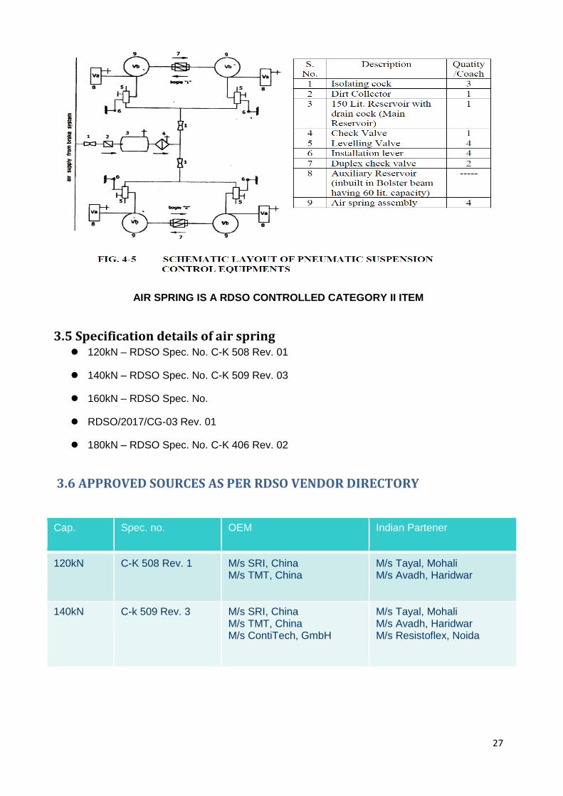
3.2 History of Development of Air Spring In India
Efforts began in mid 1990s
First lot of Air springs for EMUs (150 kN capacity) was supplied in 1998.
Presently four variants of air springs being used
– For EMUs/3 Phase MEMUs (180 kN),
– For ICF and Hybrid Coaches (140kN),and
– LHB Coaches (120 kN & 140 kN).
– LHB Coaches (160kN) under trial.
3.3 AIR SPRING Vs STEEL SPRINGS
Air Springs Steel Coil Springs
Load Proportionate Stiffness i.e. Higher stiffness with greater load and vice versa.
Linear Stiffness characteristics
Maintains constant floor height Floor height reduces with increasing load
Better ride comfort and higher speed potential Ride comfort and speed potential limited by characteristics
Isolation of structural and high frequency noises No noise isolation

26
3.4 TECHNICAL REQUIREMENT
Desc. 120kN 140kN 180kN
Min. tare Load 60kN 50kN 50kN
Max. full Load 120kN 140kN 180kN
Max. Vertical Deflection ± 30 mm ± 30 mm ± 30 mm
Max. Lateral Deflection ± 80 mm ± 60 mm ± 60 mm
Vertical Stiffness 500 ± 75N/mm (With add. Volume-60dm³)
700 ± 100N/mm (With add. Volume-40dm³)
700 ± 100N/mm (With add. Volume-40dm³)
Lateral Stiffness 175 ± 30N/mm 200 ± 30N/mm 500 ± 100N/mm
Installed Height 294+0/-5 255 +0/-5 255 +0/-5
Bursting Strength Checked at 30Kg/cm² for 5 min.
Leakage Test Checked at 9/6Kg /cm² & press. Drop within 1% of test pr.
FIAT BOGIE WITH AIR SPRING IN SECONDARY SUSPENSION
LAYOUT OF PNEUMATIC SUSPENSION CONTROL EQUIPMENT
27
AIR SPRING IS A RDSO CONTROLLED CATEGORY II ITEM
3.5 Specification details of air spring 120kN – RDSO Spec. No. C-K 508 Rev. 01
140kN – RDSO Spec. No. C-K 509 Rev. 03
160kN – RDSO Spec. No.
RDSO/2017/CG-03 Rev. 01
180kN – RDSO Spec. No. C-K 406 Rev. 02
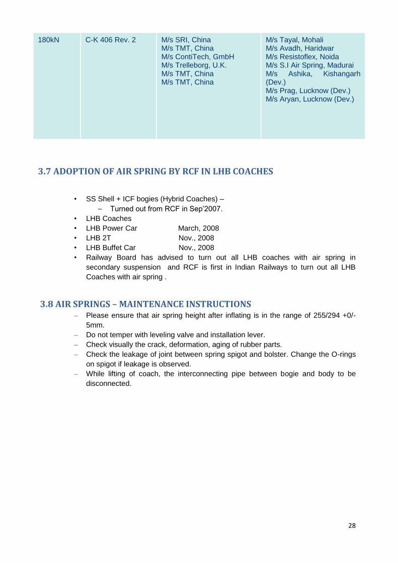
3.6 APPROVED SOURCES AS PER RDSO VENDOR DIRECTORY
Cap. Spec. no. OEM Indian Partener
120kN C-K 508 Rev. 1 M/s SRI, China M/s TMT, China
M/s Tayal, Mohali M/s Avadh, Haridwar
140kN C-k 509 Rev. 3 M/s SRI, China M/s TMT, China M/s ContiTech, GmbH
M/s Tayal, Mohali M/s Avadh, Haridwar M/s Resistoflex, Noida
28
180kN C-K 406 Rev. 2 M/s SRI, China M/s TMT, China M/s ContiTech, GmbH M/s Trelleborg, U.K. M/s TMT, China M/s TMT, China
M/s Tayal, Mohali M/s Avadh, Haridwar M/s Resistoflex, Noida M/s S.I Air Spring, Madurai M/s Ashika, Kishangarh (Dev.) M/s Prag, Lucknow (Dev.) M/s Aryan, Lucknow (Dev.)
3.7 ADOPTION OF AIR SPRING BY RCF IN LHB COACHES
• SS Shell + ICF bogies (Hybrid Coaches) –
– Turned out from RCF in Sep’2007.
• LHB Coaches
• LHB Power Car March, 2008
• LHB 2T Nov., 2008
• LHB Buffet Car Nov., 2008
• Railway Board has advised to turn out all LHB coaches with air spring in
secondary suspension and RCF is first in Indian Railways to turn out all LHB
Coaches with air spring .
3.8 AIR SPRINGS – MAINTENANCE INSTRUCTIONS – Please ensure that air spring height after inflating is in the range of 255/294 +0/-
5mm.
– Do not temper with leveling valve and installation lever.
– Check visually the crack, deformation, aging of rubber parts.
– Check the leakage of joint between spring spigot and bolster. Change the O-rings
on spigot if leakage is observed.
– While lifting of coach, the interconnecting pipe between bogie and body to be
disconnected.
29
3.9 AIR SPRINGS – ADVANTAGES Fewer variants required to be stocked for various coaches
No compensating rings are required for buffer height adjustment.
Easy buffer height adjustment by installation lever.
Low maintenance.
Wheel life increased due to improvement in lateral riding index. Maintain constant height
at varying load
Less failures as compared to helical springs
Air Spring is capable to run at 60Kmph in deflated condition.
3.10. ADOPTION OF AIR SPRING BY RCF IN LHB COACHES • SS Shell + ICF bogies (Hybrid Coaches) –
– Turned out from RCF in Sep’2007.
• LHB Coaches
• LHB Power Car March, 2008
• LHB 2T Nov., 2008
• LHB Buffet Car Nov., 2008
• Railway Board has advised to turn out all LHB coaches with air spring in
secondary suspension and RCF is first in Indian Railways to turn out all LHB
Coaches with air spring .
3.11. AIR SPRINGS – MAINTENANCE INSTRUCTIONS – Please ensure that air spring height after inflating is in the range of 255/294 +0/-
5mm.
– Do not temper with leveling valve and installation lever.
– Check visually the crack, deformation, aging of rubber parts.
– Check the leakage of joint between spring spigot and bolster. Change the O-rings
on spigot if leakage is observed.
– While lifting of coach, the interconnecting pipe between bogie and body to be
disconnected.
3.12. AIR SPRINGS – ADVANTAGES Fewer variants required to be stocked for various coaches
No compensating rings are required for buffer height adjustment.
Easy buffer height adjustment by installation lever.
Low maintenance.
30
Wheel life increased due to improvement in lateral riding index. Maintain constant height
at varying load
Less failures as compared to helical springs
Air Spring is capable to run at 60Kmph in deflated condition.
3.13. AIR SPRINGS – RUNNING CARE – Coaches with deflated springs not to be run beyond 60kmph
– Feed pipe feeds the air for springs and must be active
– Air spring height/coach clearances to be maintained as per drg .
– Provide a safety plate for leveling valve to avoid stone hitting etc.
– Ensure that all the fasteners are properly tightened.
– Check the leakage of all air joints and rectify, if required.
– Ensure that installation lever is in position and tightened properly.
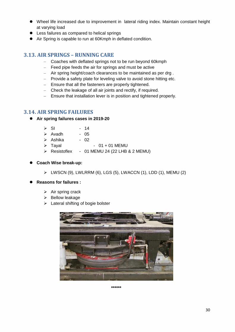
3.14. AIR SPRING FAILURES Air spring failures cases in 2019-20
SI - 14
Avadh - 05
Ashika - 02
Tayal - 01 + 01 MEMU
Resistoflex - 01 MEMU 24 (22 LHB & 2 MEMU)
Coach Wise break-up:
LWSCN (9), LWLRRM (6), LGS (5), LWACCN (1), LDD (1), MEMU (2)
Reasons for failures :
Air spring crack
Bellow leakage
Lateral shifting of bogie bolster
******
31
Article Title & Index
4. An Overview of Machinery & Plant Maintenance Activities at RCF – by Sh Vineet Singhal, CPE/RCF
A. Introduction B. A glance at key statistics
Age analysis of critical machines
Failures percentage by cause types:Mechanical/Electrical/operator/Electronic etc):
C. Energy Management Through Online Monitoring of Power Consumption:
Electricity consumption during the year 2019-20
D. Implementation of Industry 4.0
Benefits of industry 4.0 techniques
Using this system, following functions can be performed:
E. Recent Technological Advancement in Machines Available at RCF
Plasma Profile Cutting Machine
CNC Hydraulic Press Brake:
Laser Cutting Machine:
Fiber laser cutter benefits include
F. Important Maintenance Areas of Concern for better Performance of Laser Machines:
RCF Experience of Safety Measures while working with LASERs:
CNC Pipe Bending Machine:
G. Electronic maintenance of Machines at RCF
Motion Control:
Position loop:
Velocity loop:
Current loop:
Bandwidth:
Tuning:
General causes for the failure of electronics in CNC and Plant Machinery
Precaution to be observed:
Ensure proper power supply:
Learnings in Covid pandemic:
H. Various safety drives for Plant assets by RCF Plant Maintenance team:
I. Further scope of improvement in plant maintenance activities:
32
VINEET SINGHAL,
CHIEF PLANT ENGINEER RAIL COACH FACTORY, KAPURTHALA
An Overview
of Machinery & Plant Maintenance Activities at RCF
Synopsis: Modern machine and its maintenance at RCF/ RAMS at RCF: a
mammoth task on course
Plant group of RCF has been playing a pivotal role in RCF Coach Production. Plant
Group is equipped with state-of-art equipments and machineries of about 2111
machineries costing around Rs. 700 Cr. These machines not only include CNC machines
like Laser Cutting & Welding machines, Spot Welding machines, 5-axis Milling machines
etc. but also all type of material Handling equipments like FLTs, EOT Cranes, Traversers
etc. Plant Group has been successful in
maintaining all the assets in an efficient manner. Availability, performance and
Maintainability has been taken care of with the help of special monitoring tools like
Industry 4.0, close monitoring and liaisoning of spares, scheduled maintenance practices,
in-house fault diagnostic capabilities and proper training of staff.
Plant Group is also been successful in efficiently monitoring daily energy consumption
which is about 200 MWh through a total of 255 networked digital energy meters with 3%
savings target (YOY basis).
Development of automation team, providing a more structured mechanism for efficient
utilization of Industry 4.0 and training on emerging Industrial practices are next on cards
for enhancing in-house competency level.
A. Introduction: Rail Coach Factory (RCF)is the premium passenger coaches
manufacturing unit of Indian Railways with current production rate of six coaches per day
to LHB design shells. The factory has designed, manufactured and exported the coaches
for various countries in the past. State- of -the- art production control measures and Plant
&Machinery at RCF has been instrumental in these achievements. RCF boasts of a total
of 2111 machineries costing about Rs. 700 Crores. These include precision LASER
based cutting & welding machines, underwater plasma arc cutting machines, robotic spot
welding machines, robotic bolster manufacturing machines, 5 axis CNC milling machines
and various similar machines. The factory also owns more than 54 EOT cranes besides
33
many more material handling devices like Fork lifters, Traversers, Rail cum road vehicles
and other material handling equipment.
Timely upkeep &maintenance of such a large number of machines has been a mammoth exercise. For this purpose, machines have been categorized into Critical CNC & Non-CNC classes. Special monitoring tools like industry 4.0 have been installed on all critical CNC machines. The MTBF (Mean Time Between Failure) and MTTR (Mean Time to Repair) are KPIs under close monitoring. Year-round meticulous spares planning, AMCs, scheduled preventive maintenances, availability of consumables/spares, close liaison with spares suppliers, OEM based maintenance of domain specific modules, in-house expertise to identify and diagnose pre-failure symptoms, regular training, interactions and refresher courses for operators are key factors due to which MTTR and MTBF are maintained under control and within targets specified in RCF’s quality management systems.
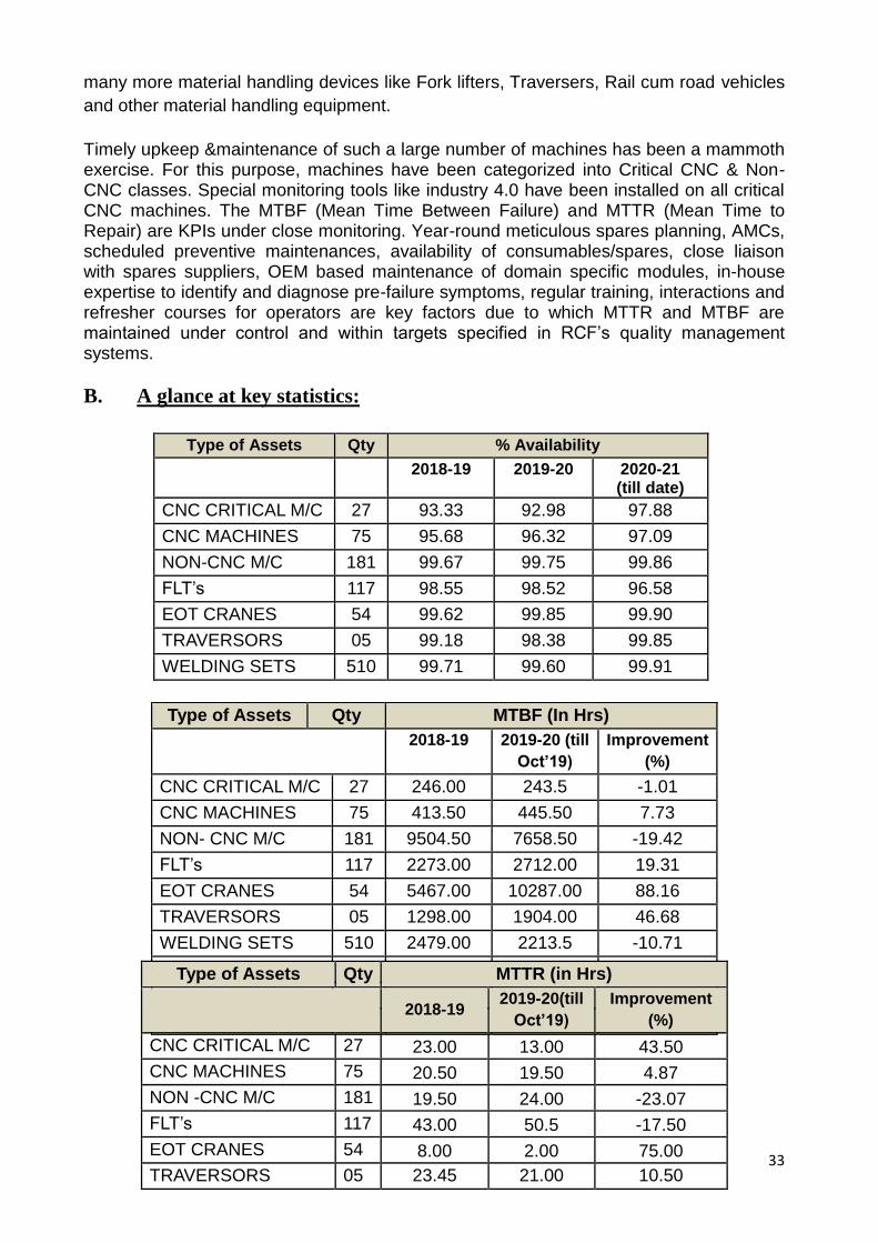
B. A glance at key statistics:
Type of Assets Qty % Availability
2018-19 2019-20 2020-21
(till date)
CNC CRITICAL M/C 27 93.33 92.98 97.88
CNC MACHINES 75 95.68 96.32 97.09
NON-CNC M/C 181 99.67 99.75 99.86
FLT’s 117 98.55 98.52 96.58
EOT CRANES 54 99.62 99.85 99.90
TRAVERSORS 05 99.18 98.38 99.85
WELDING SETS 510 99.71 99.60 99.91
Type of Assets Qty MTBF (In Hrs)
2018-19 2019-20 (till
Oct’19)
Improvement
(%)
CNC CRITICAL M/C 27 246.00 243.5 -1.01
CNC MACHINES 75 413.50 445.50 7.73
NON- CNC M/C 181 9504.50 7658.50 -19.42
FLT’s 117 2273.00 2712.00 19.31
EOT CRANES 54 5467.00 10287.00 88.16
TRAVERSORS 05 1298.00 1904.00 46.68
WELDING SETS 510 2479.00 2213.5 -10.71
COMPRESSORS 40 11601 6907.5 -40.45
Type of Assets Qty MTTR (in Hrs)
2018-19
2019-20(till
Oct’19)
Improvement
(%)
CNC CRITICAL M/C 27 23.00 13.00 43.50
CNC MACHINES 75 20.50 19.50 4.87
NON -CNC M/C 181 19.50 24.00 -23.07
FLT’s 117 43.00 50.5 -17.50
EOT CRANES 54 8.00 2.00 75.00
TRAVERSORS 05 23.45 21.00 10.50
34
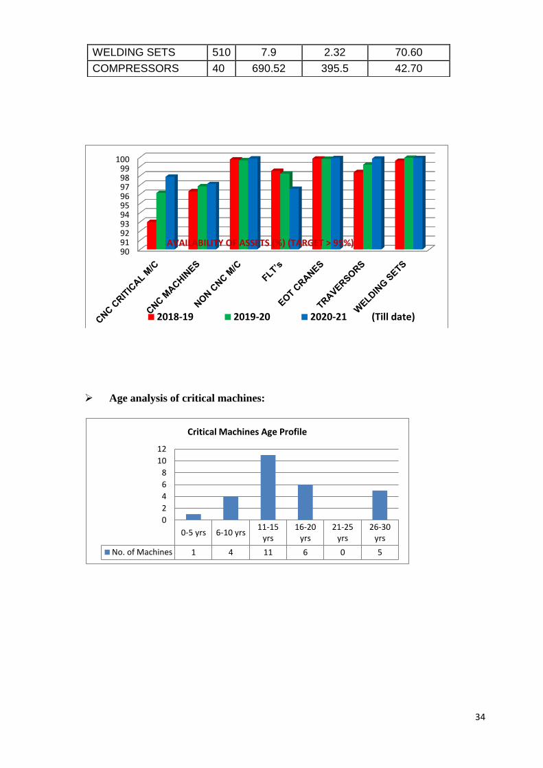
Age analysis of critical machines:
90919293949596979899
100
2018-19 2019-20 2020-21 (Till date)
0-5 yrs 6-10 yrs11-15
yrs16-20
yrs21-25
yrs26-30
yrs
No. of Machines 1 4 11 6 0 5
0
2
4
6
8
10
12
Critical Machines Age Profile
WELDING SETS 510 7.9 2.32 70.60
COMPRESSORS 40 690.52 395.5 42.70
AVAILABILITY OF ASSETS (%) (TARGET > 95%)
35
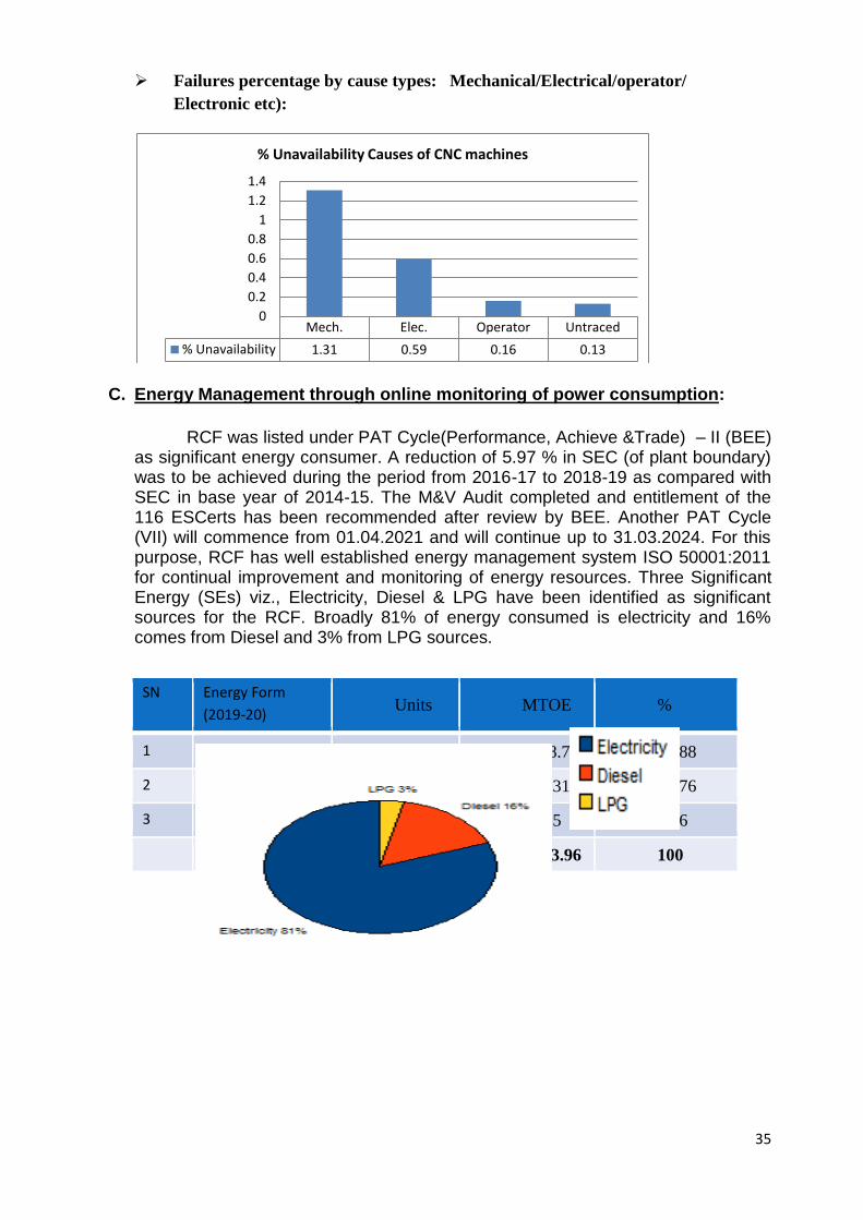
Failures percentage by cause types: Mechanical/Electrical/operator/
Electronic etc):
C. Energy Management through online monitoring of power consumption:
RCF was listed under PAT Cycle(Performance, Achieve &Trade) – II (BEE)
as significant energy consumer. A reduction of 5.97 % in SEC (of plant boundary) was to be achieved during the period from 2016-17 to 2018-19 as compared with SEC in base year of 2014-15. The M&V Audit completed and entitlement of the 116 ESCerts has been recommended after review by BEE. Another PAT Cycle (VII) will commence from 01.04.2021 and will continue up to 31.03.2024. For this purpose, RCF has well established energy management system ISO 50001:2011 for continual improvement and monitoring of energy resources. Three Significant Energy (SEs) viz., Electricity, Diesel & LPG have been identified as significant sources for the RCF. Broadly 81% of energy consumed is electricity and 16% comes from Diesel and 3% from LPG sources.
Mech. Elec. Operator Untraced
% Unavailability 1.31 0.59 0.16 0.13
0
0.2
0.4
0.6
0.8
1
1.2
1.4
% Unavailability Causes of CNC machines
SN Energy Form
(2019-20) Units MTOE %
1 Electricity (kWh) 14519754 1248.7 80.88
2 Diesel (lts) 248698 243.31 15.76
3 LPG (kg) 78416 51.95 3.36
Total
1543.96 100

36
Electricity consumption during the year 2019-20:
S.No Area
Units in kWh Consumption %age in area
1 Workshop 11526292 47.87
2 Recoverable 8702657 36.14
3 Water pump 1085933 4.51
4 Admin Bldg 1902529 7.90
5 Others 860141 3.57
Total 24077552 100
In order to monitor factory’s overall daily electric energy consumption for about 20 MWh, a total of 255 networked digital energy meters have been installed in all the 11 sub-stations, which can provide real-time information online to all users. Energy consumption data -shop-wise, machine wise, sub-station wise, daily, monthly analysisare now available online so as to monitor and control the idle activities.RCF has set a target of 3% energy saving (YoY basis). Now it is possible to monitor shop-wise energy consumption data by each shop in-charges and take steps to control wastage of energy. The energy consumption details can be seen online.Various steps like occupancy sensors recycle timer for man-coolers, Replacement with energy efficient fittings, provision of energy saver in compressor houses etc are being taken regularly.
D. Implementation of Industry 4.0:
Industry 4.0 viz., fourth industrial revolutionin essence is the trend towards
automation and data exchange in manufacturing technologiesand processes which include Cyber-physical system(CPS), internet of things(IoT), cloud computing, cognitive computing and artificial intelligence.
Evolution of Industry 4.0

37
Benefits of industry 4.0 techniques
Industry 4.0 solution implemented at RCF is completely Made -in -India developed by
non-Railway agency. The system is web based with wireless environment giving
connectivity with NC machines without Ethernet Port, established by installing DCU
(Data Control Unit) on machine.
Connectivity of critical machines to Industry 4.0
network in RCF
1 Wheel Shop 07
2 Machine Shop 03
3 Bogie Shop 10
4 Sheet Metal Shop 17
Total 37
Using this system, following functions can be performed:
View Dashboard in different format (Machine and Shop wise)
View Machine performance (Day wise, Shift wise and live)
Machine Alarms and Event logs.
Machine Program Management.
Production and Maintenance planning.
Maintenance task management.
Help make efficient use of machines and thereby improve productivity.
Analyse machine parameters in real time.
38
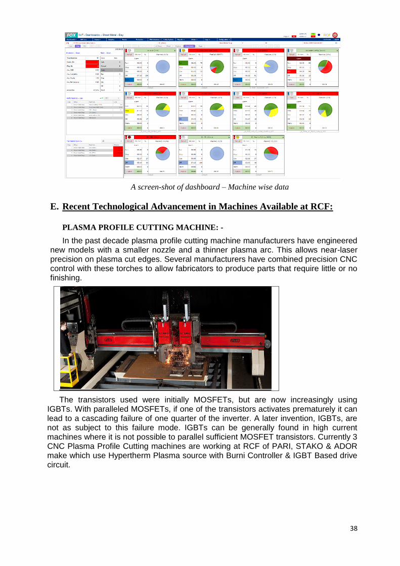
A screen-shot of dashboard – Machine wise data
E. Recent Technological Advancement in Machines Available at RCF:
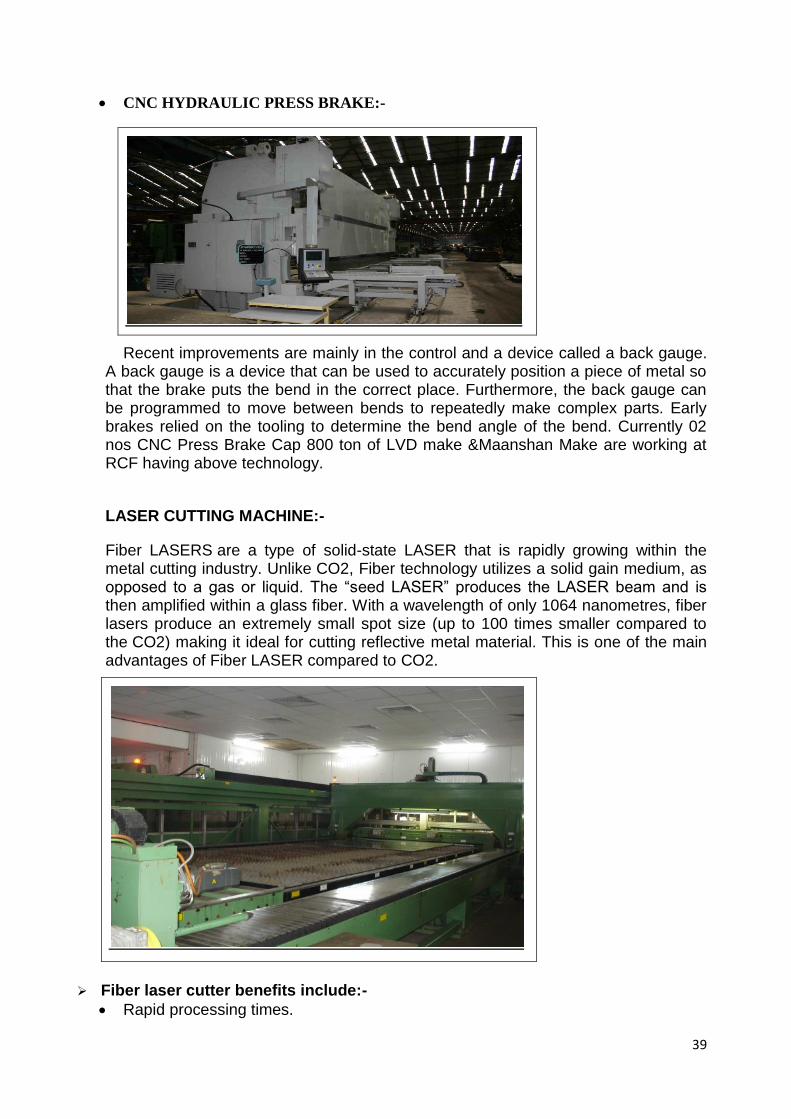
PLASMA PROFILE CUTTING MACHINE: -
In the past decade plasma profile cutting machine manufacturers have engineered new models with a smaller nozzle and a thinner plasma arc. This allows near-laser precision on plasma cut edges. Several manufacturers have combined precision CNC control with these torches to allow fabricators to produce parts that require little or no finishing.
The transistors used were initially MOSFETs, but are now increasingly using IGBTs. With paralleled MOSFETs, if one of the transistors activates prematurely it can lead to a cascading failure of one quarter of the inverter. A later invention, IGBTs, are not as subject to this failure mode. IGBTs can be generally found in high current machines where it is not possible to parallel sufficient MOSFET transistors. Currently 3 CNC Plasma Profile Cutting machines are working at RCF of PARI, STAKO & ADOR make which use Hypertherm Plasma source with Burni Controller & IGBT Based drive circuit.
39
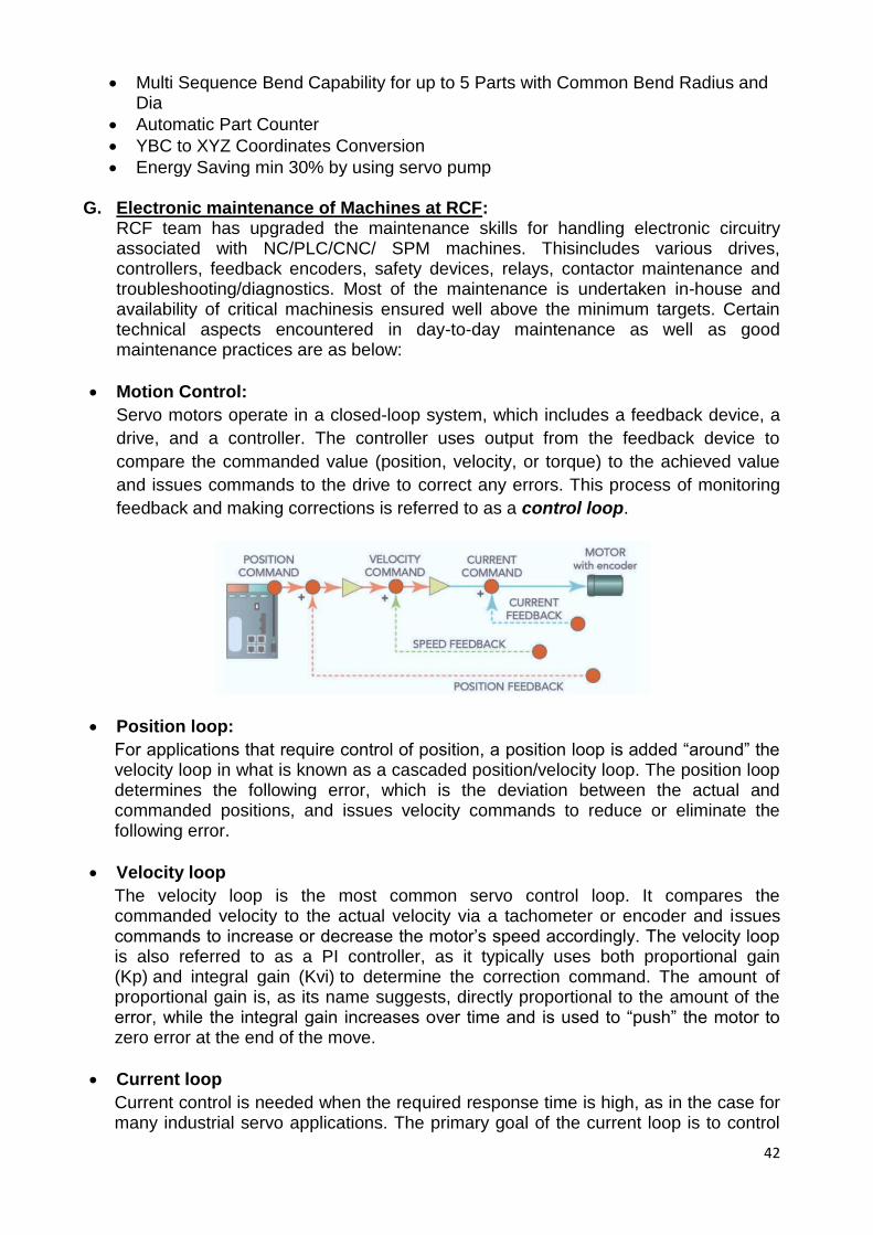
CNC HYDRAULIC PRESS BRAKE:-
Recent improvements are mainly in the control and a device called a back gauge. A back gauge is a device that can be used to accurately position a piece of metal so that the brake puts the bend in the correct place. Furthermore, the back gauge can be programmed to move between bends to repeatedly make complex parts. Early brakes relied on the tooling to determine the bend angle of the bend. Currently 02 nos CNC Press Brake Cap 800 ton of LVD make &Maanshan Make are working at RCF having above technology.
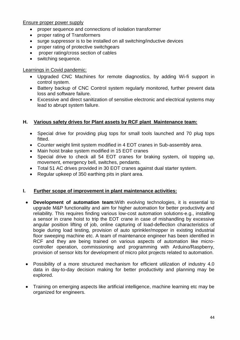
LASER CUTTING MACHINE:-
Fiber LASERS are a type of solid-state LASER that is rapidly growing within the metal cutting industry. Unlike CO2, Fiber technology utilizes a solid gain medium, as opposed to a gas or liquid. The “seed LASER” produces the LASER beam and is then amplified within a glass fiber. With a wavelength of only 1064 nanometres, fiber lasers produce an extremely small spot size (up to 100 times smaller compared to the CO2) making it ideal for cutting reflective metal material. This is one of the main advantages of Fiber LASER compared to CO2.
Fiber laser cutter benefits include:-
Rapid processing times.

40
Reduced energy consumption & bills – due to greater efficiency.
Greater reliability and performance - no optics to adjust or align and no lamps to replace.
Minimal maintenance.
Higher productivity - lower operational costs offer a greater return on your investment.
Currently 02 Nos LVD Make, 01 No Trumf make, 01 no HK laser Make, 01 no Balliu make & 1 no TTM make Laser machines are working at RCF with CO2 based slab type Laser & 01 machine of m/S BALLIU make is under procurement having Fiber Laser Technology at RCF.
F. Important Maintenance Areas of concern for better performance of Laser Machines:- The major area responsible for performance of laser machines which are normally being ignored:-
Quality of Gas (LASER& assist gas purity level)
Quality of water (used for cooling of resonator, HV control unit & optics)
Quality of Air (moist free dry air used for purging of optics)
Quality of input power supply.
The centering of cutting nozzle shall be carried out at start of every shift it hardly takes 5-7 minutes and give betternozzle life and burr free cutting quality.
Different optics of machines shall be cleaned with proper quality of tissue paper, cotton & extra high pure acetone for their better life span.
The proper working of fume suction doors fixed under the cutting table must be ensured otherwise fine cutting dust will entrap in the moving parts & optics of machine thus affect the life of moving parts/optics.
The cutting table grits must be replaced/ cleaned within time otherwise the heavy deposited slag will affect the quality of cut and reduce the life of lens.
The spares and consumables shall be of standard make as advised by the OEM for better reliability and availability of machine.
The resonator of machine must be filled to atmospheric pressure with laser premixed or nitrogen gas as per machine design prior to switching of the machine to avoid contamination of internal optics it will give consistent/optimum laser power with better optics life.
Predictive maintenance technique shall be adopted to avoid major failures.
Certain spares like filters, oil, water etc. which are supposed to be replaced within specified time limit must be displayed on particular assembly of machine.
All laser machines at RCF have been displayed with documents pasted on all major assembly like chiller unit, dust collector & Resonator with last date of replacement and next due date so that important spares / consumable must be replaced within time without any fail. (*The above areas if properly addressed as per guideline of OEM specifications the major problems related to quality and maintenance can be bought under control. These areas are normally being ignored and not given much importance ultimately enhance the down time & spares cost both.)

41
RCF Experience of Safety Measures while working with LASERs
CO2 LASER used for industrial application is a class IV LASER with protected LASER path keeping safety aspects of human as LASER beam is an invisible beam and may damage the eyes permanently orburn the skin in depth if comes into direct contact. Poor quality of gas/ purging air responsible for diversion of LASER beam & burning of mirror surface may lead to major fire accident.
The fire-retardant bellows shall be used as beam ducting bellows which can control the spreading of fire, such bellows only damage in that particular area where the LASER beam hit and not catching fire.
RCF has developed two types of indigenous fire-retardant bellows which will be fixed in the most prone to fire area on LVD laser machines. The cloth of fire retardant bellows can bear temp. up to 400 degree centigrade.
During LASER beam alignment safety goggles are must as there are special goggles which can protect penetration of laser beam to eyes.
During higher PMS of LASER machines all laser ducting bellows shall be removed & checked from inside for any damage & timely rectification/ replacement of same can protect major fire accident.
All safety devices & their proper working on the machines must be ensured during higher preventive maintenance schedules.
Proper selection of safety goggles for protection of eyes of the operators and maintainers against LASER.
CNC Pipe Bending Machine: -
CNC Pipe Bending Machines are used to form the work piece into the shape of a die. Straight tube stock can be formed using a bending machine to create a variety of single or multiple bends and to shape the piece into the desired form. These processes can be used to form complex shapes out of different types of ductile metal tubing. Currently 02 nos-5 Axis- CNC Pipe Bending machines of M/s Naveen Hydrocontol& M/s Hydropack Makeare working at RCF.
Main feature of 5 axis CNC Pipe Bending Machine available in RCF are as below:-
15 Bends programme
Clockwise Bending
Large / Multiple programme Data Storage Facility in Flash Disk/Hard Disk
Bend Arm Over Ride Switch to prevent Bend Arm / Machine Collision
Programmable Variable Speeds for each Axis
42
Multi Sequence Bend Capability for up to 5 Parts with Common Bend Radius and Dia
Automatic Part Counter
YBC to XYZ Coordinates Conversion
Energy Saving min 30% by using servo pump
G. Electronic maintenance of Machines at RCF: RCF team has upgraded the maintenance skills for handling electronic circuitry associated with NC/PLC/CNC/ SPM machines. Thisincludes various drives, controllers, feedback encoders, safety devices, relays, contactor maintenance and troubleshooting/diagnostics. Most of the maintenance is undertaken in-house and availability of critical machinesis ensured well above the minimum targets. Certain technical aspects encountered in day-to-day maintenance as well as good maintenance practices are as below:
Motion Control:
Servo motors operate in a closed-loop system, which includes a feedback device, a
drive, and a controller. The controller uses output from the feedback device to
compare the commanded value (position, velocity, or torque) to the achieved value
and issues commands to the drive to correct any errors. This process of monitoring
feedback and making corrections is referred to as a control loop.
Position loop:
For applications that require control of position, a position loop is added “around” the velocity loop in what is known as a cascaded position/velocity loop. The position loop determines the following error, which is the deviation between the actual and commanded positions, and issues velocity commands to reduce or eliminate the following error.
Velocity loop
The velocity loop is the most common servo control loop. It compares the commanded velocity to the actual velocity via a tachometer or encoder and issues commands to increase or decrease the motor’s speed accordingly. The velocity loop is also referred to as a PI controller, as it typically uses both proportional gain (Kp) and integral gain (Kvi) to determine the correction command. The amount of proportional gain is, as its name suggests, directly proportional to the amount of the error, while the integral gain increases over time and is used to “push” the motor to zero error at the end of the move.
Current loop
Current control is needed when the required response time is high, as in the case for many industrial servo applications. The primary goal of the current loop is to control

43
torque, which influences speed, and therefore, position. The current loop is typically nested inside the velocity loop, making current the innermost loop, with the velocity loop in the middle, and the position loop being the outermost loop. Current loops are typically PI controllers, with both proportional and integral gains. Current control parameters are often set by the manufacturer, saving the user the time and effort of tuning the current control loop.
Bandwidth
In any cascaded system, the response time, or bandwidth, of the inner loop must be faster than the response time of the outer loop. The general rule for nested servo control loops is that the velocity loop should have a bandwidth that is anywhere from 5 to 10 times that of the position loop, and the current loop should have a bandwidth that is 5 to 10 times that of the velocity loop.
Tuning
Cascaded position/velocity loops are tuned inside-out, and either four or five parameters are set by the user. The inner velocity loop (usually a PI controller) is tuned first, and then the outer position loop (generally either a PI or PID controller) is tuned. In house tuning of servo motion control loop for X, Y, XX Axis is carried out in upgrade and commissioning of latest Lincoln electric (Burny USA) control system for STAKO underwater plasma cutting Machine.
General causes for the failure of electronics in CNC and Plant Machinery.
Dust,Corrosive fumes (coming from coolant interacting with the hot chips)
Oil/Coolant dripping through cables.
Condensation of moisture
High temperature and Excess humidity in control panels.
Insects/Rodents.
Poor ventilation and Air leakage.
Improper power supply.
Improper earthling.
Insulation Failure and power leakage.
Loose connections and bare control wirings.
Non-conformance to EMI (Electro Magnetic Interference) guidelines.
Precaution to be observed
Secure panel and pendant sealing.
Maintain gasket in the good condition.
proper orientation and direction of the exhaust fans
recommended coolant
Ensure proper sealing at the entry of the cables
Maintain right temperature and Humidity of the A/C systems inside control panel.
No insects and pests come near to Control Panels.
Periodic cleaning of the filters of A/C Systems.
Periodic tightening of cable connections and avoiding bare wires.
Guidelines against EMI as laid by OEM.
Safe working at high voltages and high frequency in laser machines.
44
Ensure proper power supply
proper sequence and connections of isolation transformer
proper rating of Transformers
surge suppressor is to be installed on all switching/inductive devices
proper rating of protective switchgears
proper rating/cross section of cables
switching sequence. Learnings in Covid pandemic:
Upgraded CNC Machines for remote diagnostics, by adding Wi-fi support in control system.
Battery backup of CNC Control system regularly monitored, further prevent data loss and software failure.
Excessive and direct sanitization of sensitive electronic and electrical systems may lead to abrupt system failure.
H. Various safety drives for Plant assets by RCF plant Maintenance team:
Special drive for providing plug tops for small tools launched and 70 plug tops fitted.
Counter weight limit system modified in 4 EOT cranes in Sub-assembly area.
Main hoist brake system modified in 15 EOT cranes
Special drive to check all 54 EOT cranes for braking system, oil topping up, movement, emergency bell, switches, pendants.
Total 51 AC drives provided in 30 EOT cranes against dual starter system.
Regular upkeep of 350 earthing pits in plant area.
I. Further scope of improvement in plant maintenance activities:
Development of automation team:With evolving technologies, it is essential to upgrade M&P functionality and aim for higher automation for better productivity and reliability. This requires finding various low-cost automation solutions-e.g., installing a sensor in crane hoist to trip the EOT crane in case of mishandling by excessive angular position lifting of job, online capturing of load-deflection characteristics of bogie during load testing, provision of auto sprinkler/mopper in existing industrial floor sweeping machine etc. A team of maintenance engineer has been identified in RCF and they are being trained on various aspects of automation like micro-controller operation, commissioning and programming with Arduino/Raspberry, provision of sensor kits for development of micro pilot projects related to automation.
Possibility of a more structured mechanism for efficient utilization of industry 4.0 data in day-to-day decision making for better productivity and planning may be explored.
Training on emerging aspects like artificial intelligence, machine learning etc may be organized for engineers.

45
The dedicated team of plant group of RCF has come a long way in developing
competency in handling maintenance requirement of sophisticated state of the art
machines like LASERS, Plasmas, CNCs, PLC etc. The team has always supported the
production activities beyond expectations given the criticality of time of breakdown
affecting production plan. Targets of MTTR /MTBF have been surpassed by plant group.
M&P facilities of RCF are a benchmark for surrounding industrial set ups. Under the
visionary leadership, RCF is making strides to surpass expectations of the variety of
national and international customized rolling stock requirements.
*****

46
Article Title & Index
5 . EN 45545- Fire protection of railway vehicles – by Sh Abhey Priya, Dy
CME/D-II
Overview of EN45545
Parameters that describes fire behavior
Hazard Levels
How to select rail components
TESTING
RCF Specifications mentioning Fire Characteristics as per EN 45545-2
Under consideration

47
Abhey Priya, Dy CME/D-II
EN 45545- Fire protection of railway vehicle:
Synopsis: EN 45545 specifies the reaction to fire performance requirements for
materials and products used on railway vehicles. The measures and requirements
specified in EN 45545 are intended to protect passengers and staff in railway vehicles in
the event of a fire on board.EN 45545 specifies fire protection measures for railway
vehicles, verification methods for these measures.
The operation and design categories defined in EN 45545-2 are used to establish hazard
levels that are used as the basis of a classification system. For each hazard level, this
part specifies the test methods, test conditions and reaction to fire performance
requirements.
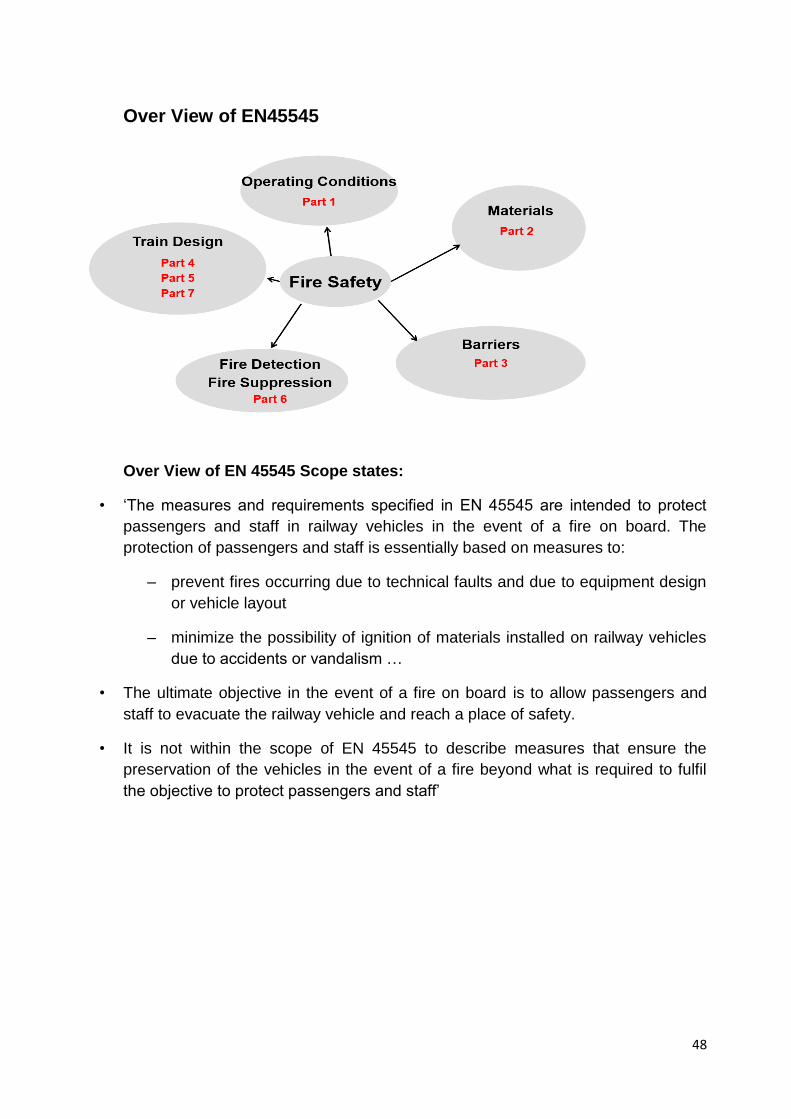
5.1 Overview of EN45545
• EN 45545: Railway applications — Fire protection on railway vehicles in 7 parts
Part 1: General
Part 2: Requirements for fire behavior of materials and components
Part 3: Fire resistance requirements for fire barriers
Part 4: Fire safety requirements for railway rolling stock design
Part 5: Fire safety requirements for electrical equipment including that of trolley
buses, track guided buses and magnetic levitation vehicles
Part 6: Fire control and management systems
Part 7: Fire safety requirements for flammable liquid and flammable gas
installations
48
Over View of EN45545
Over View of EN 45545 Scope states:
• ‘The measures and requirements specified in EN 45545 are intended to protect
passengers and staff in railway vehicles in the event of a fire on board. The
protection of passengers and staff is essentially based on measures to:
– prevent fires occurring due to technical faults and due to equipment design
or vehicle layout
– minimize the possibility of ignition of materials installed on railway vehicles
due to accidents or vandalism …
• The ultimate objective in the event of a fire on board is to allow passengers and
staff to evacuate the railway vehicle and reach a place of safety.
• It is not within the scope of EN 45545 to describe measures that ensure the
preservation of the vehicles in the event of a fire beyond what is required to fulfil
the objective to protect passengers and staff’

49
5.2 Parameters that describes fire behavior • Ignitability – spread of flame (CFE: critical flux at extinguishment)
• Heat release (MAHRE)
• Smoke (loss of visibility: Ds4, VOF4)
• Toxicity (CITg)

50
5.3 Hazard Levels
• Railway vehicles are classified in accordance with the fire hazard level associated
with their design and operation.
• The three hazard levels are: HL1, HL2 and HL3 with HL1 being the lowest
requirement and HL3 being the highest.
• The classification depends on how many kilometres the trolley is in tunnels and
whether it is automatic, two-storey or if sleepers are on board.
5.4 How to select rail components • Determine which product requirements apply (R1-R26)
• Determine the fire hazard level (HL1-HL3)
• Identify a suitable material that meets the above ratings and the technical
requirements for the application.
5.5 TESTING • There 32 no’s Lab’s approved by CERTIFER to perform tests according to EN
45545-2. These are based in Euorpe and all are out-side India.
• Now there are sample collection centres of these Labs in India.
5.6 RCF Specifications mentioning Fire Characteristics as per EN 455452
• Thermal Insulation for under frame and sidewall as per MDTS-28001
• Resin Bonded Fiber Glass Wool Insulation Laminated On One Side With Heat Resistant
Aluminium Foil as per MDTS-207
• Single Component Water Based Sound Deadening/Dampening Spray-Able Paint for
LHB Design Coaches as per MSTS-262 Rev-01
• Two Component PU Based Sound Deadening/Dampening Spray-Able Paint for LHB
Design Coaches as MDTS-076
• Single Component Water Based Fire Barrier Intumescent Paint for IR Coaches suitable
for Internal and External Application as per MDTS 22282 Rev-01
• Adhesion Promoter primer as per MDTS-48279 Rev-03
• PVC Based Film for Coach Interiors as per MDTS-25305 Rev-01
5.7 Under consideration • FRP hand-layup Components
• Seat Upholstery
• Seat Cushioning and thermal insulation material
• Fire Barriers
• Seat Assemblies
• Environment Friendly floor covering
*******