Installing the IP Camera - cisco.com · To install the Cisco Video Surveillance 6500PD IP Camera,...
6
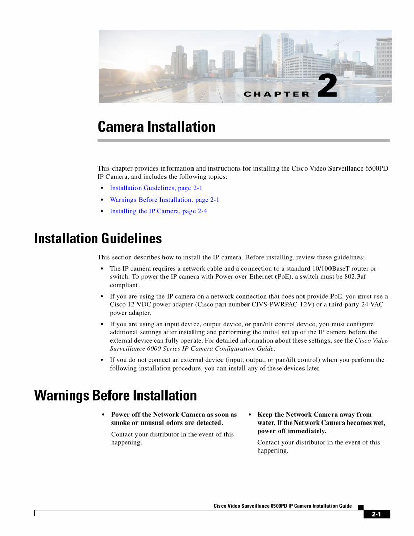
CHAPTER 2-1 Cisco Video Surveillance 6500PD IP Camera Installation Guide 2 Camera Installation This chapter provides information and instructions for installing the Cisco Video Surveillance 6500PD IP Camera, and includes the following topics: • Installation Guidelines, page 2-1 • Warnings Before Installation, page 2-1 • Installing the IP Camera, page 2-4 Installation Guidelines This section describes how to install the IP camera. Before installing, review these guidelines: • The IP camera requires a network cable and a connection to a standard 10/100BaseT router or switch. To power the IP camera with Power over Ethernet (PoE), a switch must be 802.3af compliant. • If you are using the IP camera on a network connection that does not provide PoE, you must use a Cisco 12 VDC power adapter (Cisco part number CIVS-PWRPAC-12V) or a third-party 24 VAC power adapter. • If you are using an input device, output device, or pan/tilt control device, you must configure additional settings after installing and performing the initial set up of the IP camera before the external device can fully operate. For detailed information about these settings, see the Cisco Video Surveillance 6000 Series IP Camera Configuration Guide. • If you do not connect an external device (input, output, or pan/tilt control) when you perform the following installation procedure, you can install any of these devices later. Warnings Before Installation • Power off the Network Camera as soon as smoke or unusual odors are detected. Contact your distributor in the event of this happening. • Keep the Network Camera away from water. If the Network Camera becomes wet, power off immediately. Contact your distributor in the event of this happening.
-
Upload
truongxuyen -
Category
Documents
-
view
231 -
download
0
Transcript of Installing the IP Camera - cisco.com · To install the Cisco Video Surveillance 6500PD IP Camera,...
Cisco Video
C H A P T E R 2
Camera InstallationThis chapter provides information and instructions for installing the Cisco Video Surveillance 6500PD IP Camera, and includes the following topics:
• Installation Guidelines, page 2-1
• Warnings Before Installation, page 2-1
• Installing the IP Camera, page 2-4
Installation GuidelinesThis section describes how to install the IP camera. Before installing, review these guidelines:
• The IP camera requires a network cable and a connection to a standard 10/100BaseT router or switch. To power the IP camera with Power over Ethernet (PoE), a switch must be 802.3af compliant.
• If you are using the IP camera on a network connection that does not provide PoE, you must use a Cisco 12 VDC power adapter (Cisco part number CIVS-PWRPAC-12V) or a third-party 24 VAC power adapter.
• If you are using an input device, output device, or pan/tilt control device, you must configure additional settings after installing and performing the initial set up of the IP camera before the external device can fully operate. For detailed information about these settings, see the Cisco Video Surveillance 6000 Series IP Camera Configuration Guide.
• If you do not connect an external device (input, output, or pan/tilt control) when you perform the following installation procedure, you can install any of these devices later.
Warnings Before Installation• Power off the Network Camera as soon as
smoke or unusual odors are detected.
Contact your distributor in the event of this happening.
• Keep the Network Camera away from water. If the Network Camera becomes wet, power off immediately.
Contact your distributor in the event of this happening.
2-1 Surveillance 6500PD IP Camera Installation Guide
Chapter 2 Camera InstallationWarnings Before Installation
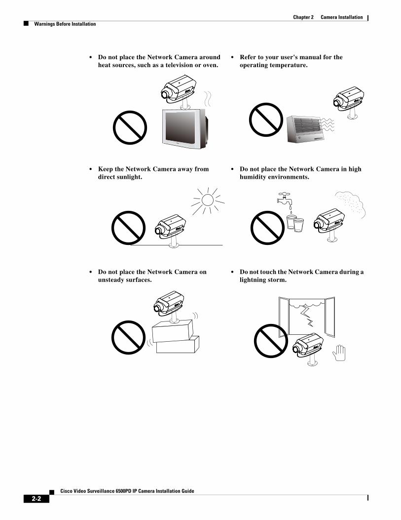
• Do not place the Network Camera around heat sources, such as a television or oven.
• Refer to your user's manual for the operating temperature.
• Keep the Network Camera away from direct sunlight.
• Do not place the Network Camera in high humidity environments.
• Do not place the Network Camera on unsteady surfaces.
• Do not touch the Network Camera during a lightning storm.
2-2Cisco Video Surveillance 6500PD IP Camera Installation Guide
Chapter 2 Camera InstallationWarnings Before Installation
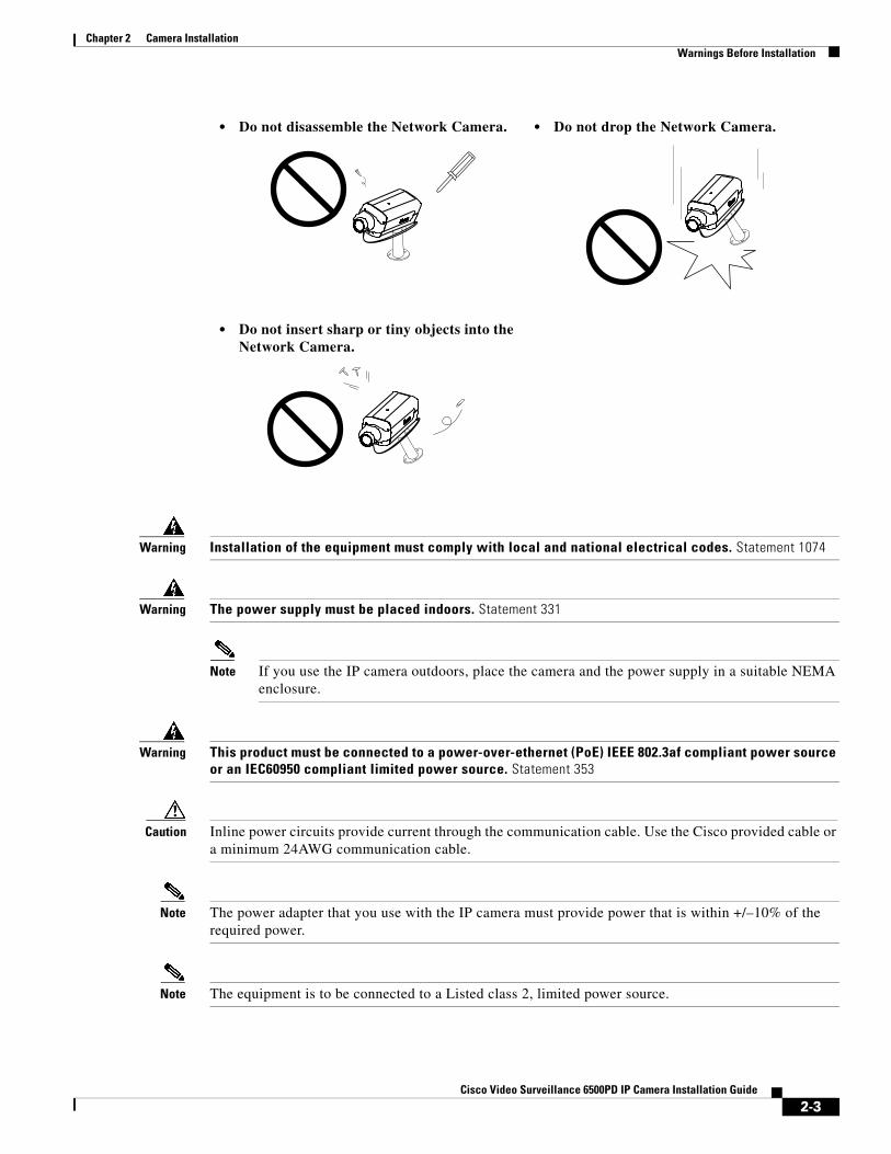
Warning Installation of the equipment must comply with local and national electrical codes. Statement 1074
Warning The power supply must be placed indoors. Statement 331
Note If you use the IP camera outdoors, place the camera and the power supply in a suitable NEMA enclosure.
Warning This product must be connected to a power-over-ethernet (PoE) IEEE 802.3af compliant power source or an IEC60950 compliant limited power source. Statement 353
Caution Inline power circuits provide current through the communication cable. Use the Cisco provided cable or a minimum 24AWG communication cable.
Note The power adapter that you use with the IP camera must provide power that is within +/–10% of the required power.
Note The equipment is to be connected to a Listed class 2, limited power source.
• Do not disassemble the Network Camera. • Do not drop the Network Camera.
• Do not insert sharp or tiny objects into the Network Camera.
2-3Cisco Video Surveillance 6500PD IP Camera Installation Guide
Chapter 2 Camera InstallationInstalling the IP Camera
Installing the IP CameraTo install the Cisco Video Surveillance 6500PD IP Camera, perform the following steps:
Procedure
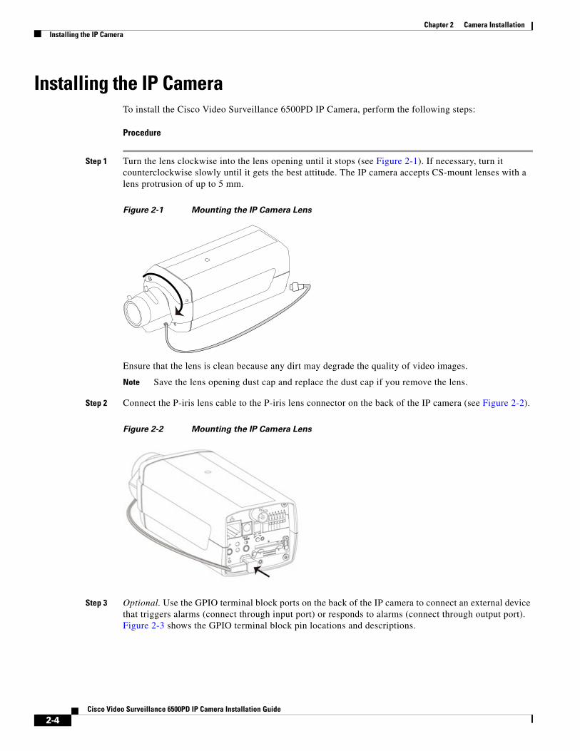
Step 1 Turn the lens clockwise into the lens opening until it stops (see Figure 2-1). If necessary, turn it counterclockwise slowly until it gets the best attitude. The IP camera accepts CS-mount lenses with a lens protrusion of up to 5 mm.
Figure 2-1 Mounting the IP Camera Lens
Ensure that the lens is clean because any dirt may degrade the quality of video images.
Note Save the lens opening dust cap and replace the dust cap if you remove the lens.
Step 2 Connect the P-iris lens cable to the P-iris lens connector on the back of the IP camera (see Figure 2-2).
Figure 2-2 Mounting the IP Camera Lens
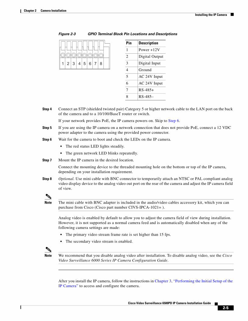
Step 3 Optional. Use the GPIO terminal block ports on the back of the IP camera to connect an external device that triggers alarms (connect through input port) or responds to alarms (connect through output port). Figure 2-3 shows the GPIO terminal block pin locations and descriptions.
2-4Cisco Video Surveillance 6500PD IP Camera Installation Guide
Chapter 2 Camera InstallationInstalling the IP Camera
Figure 2-3 GPIO Terminal Block Pin Locations and Descriptions
Step 4 Connect an STP (shielded twisted pair) Category 5 or higher network cable to the LAN port on the back of the camera and to a 10/100/BaseT router or switch.
If your network provides PoE, the IP camera powers on. Skip to Step 6.
Step 5 If you are using the IP camera on a network connection that does not provide PoE, connect a 12 VDC power adapter to the camera using the provided power connector.
Step 6 Wait for the camera to boot and check the LEDs on the IP camera.
• The red status LED lights steadily.
• The green network LED blinks repeatedly.
Step 7 Mount the IP camera in the desired location.
Connect the mounting device to the threaded mounting hole on the bottom or top of the IP camera, depending on your installation requirement.
Step 8 Optional. Use mini cable with BNC connector to temporarily attach an NTSC or PAL compliant analog video display device to the analog video out port on the rear of the camera and adjust the IP camera field of view.
Note The mini cable with BNC adapter is included in the audio/video cables accessory kit, which you can purchase from Cisco (Cisco part number CIVS-IPCA-1021= ).
Analog video is enabled by default to allow you to adjust the camera field of view during installation. However, it is not supported as a normal camera feed and is automatically disabled when any of the following camera settings are made:
• The primary video stream frame rate is set higher than 15 fps.
• The secondary video stream is enabled.
Note We recommend that you disable analog video after installation. To disable analog video, see the Cisco Video Surveillance 6000 Series IP Camera Configuration Guide.
After you install the IP camera, follow the instructions in Chapter 3, “Performing the Initial Setup of the IP Camera” to access and configure the camera.
Pin Description
1 Power +12V
2 Digital Output
3 Digital Input
4 Ground
5 AC 24V Input
6 AC 24V Input
7 RS-485+
8 RS-485–
87654321
2-5Cisco Video Surveillance 6500PD IP Camera Installation Guide
Chapter 2 Camera InstallationInstalling the IP Camera
2-6Cisco Video Surveillance 6500PD IP Camera Installation Guide