
Installing and Routing Cables BWS 1600G
30
OptiX BWS 1600G Installation Guide Contents Issue 03 (2007-04-30) Huawei Technologies Proprietary i Contents 7 Installing and Routing Cables.................................................................................................7-1 7.1 Installing and Routing Power Cables ............................................................................................................ 7-2 7.1.1 Installation Preparation ........................................................................................................................ 7-2 7.1.2 Procedure for Upward Cabling ............................................................................................................ 7-6 7.1.3 Procedure for Downward Cabling ....................................................................................................... 7-9 7.1.4 Resistance Measurement before Power-Up ....................................................................................... 7-13 7.2 Installing and Routing Alarm Cables .......................................................................................................... 7-13 7.2.1 Introduction to ALARM Interface and Cables ................................................................................... 7-13 7.2.2 Pin Assignment .................................................................................................................................. 7-16 7.2.3 Procedure for Installing Alarm Cables ............................................................................................... 7-17 7.3 Installing and Routing Clock Cables ........................................................................................................... 7-19 7.3.1 Introduction to Clock Interfaces......................................................................................................... 7-19 7.3.2 Installation Procedure ........................................................................................................................ 7-19 7.4 Installing and Routing Network Cables ...................................................................................................... 7-21 7.4.1 Connecting Network Cables .............................................................................................................. 7-21 7.4.2 Core Wire Colors of Network Cables ................................................................................................ 7-23 7.4.3 Installing Cables Between the Subrack and HUB.............................................................................. 7-25 7.4.4 Installing Network Cables Between NM Computer and HUB .......................................................... 7-26
-
Upload
cristian-neacsu -
Category
Documents
-
view
57 -
download
3
Transcript of Installing and Routing Cables BWS 1600G

OptiX BWS 1600G Installation Guide Contents
Issue 03 (2007-04-30) Huawei Technologies Proprietary i
Contents
7 Installing and Routing Cables.................................................................................................7-1 7.1 Installing and Routing Power Cables ............................................................................................................7-2
7.1.1 Installation Preparation ........................................................................................................................7-2 7.1.2 Procedure for Upward Cabling ............................................................................................................7-6 7.1.3 Procedure for Downward Cabling .......................................................................................................7-9 7.1.4 Resistance Measurement before Power-Up .......................................................................................7-13
7.2 Installing and Routing Alarm Cables ..........................................................................................................7-13 7.2.1 Introduction to ALARM Interface and Cables...................................................................................7-13 7.2.2 Pin Assignment ..................................................................................................................................7-16 7.2.3 Procedure for Installing Alarm Cables ...............................................................................................7-17
7.3 Installing and Routing Clock Cables...........................................................................................................7-19 7.3.1 Introduction to Clock Interfaces.........................................................................................................7-19 7.3.2 Installation Procedure ........................................................................................................................7-19
7.4 Installing and Routing Network Cables ......................................................................................................7-21 7.4.1 Connecting Network Cables ..............................................................................................................7-21 7.4.2 Core Wire Colors of Network Cables ................................................................................................7-23 7.4.3 Installing Cables Between the Subrack and HUB..............................................................................7-25 7.4.4 Installing Network Cables Between NM Computer and HUB ..........................................................7-26

OptiX BWS 1600G Installation Guide Figures
Issue 03 (2007-04-30) Huawei Technologies Proprietary iii
Figures
Figure 7-1 Cabinet power cable terminals..........................................................................................................7-2
Figure 7-2 Power switches .................................................................................................................................7-3
Figure 7-3 Subrack power cable terminals .........................................................................................................7-4
Figure 7-4 Connection of the power cables........................................................................................................7-5
Figure 7-5 Upward cabling for the protection grounding cables........................................................................7-7
Figure 7-6 Connection of power cables terminals ..............................................................................................7-8
Figure 7-7 Downward cabling for protection grounding cables.......................................................................7-11
Figure 7-8 Connection of power cables terminals ............................................................................................7-12
Figure 7-9 ALARM interface ...........................................................................................................................7-14
Figure 7-10 Alarm cables .................................................................................................................................7-14
Figure 7-11 The alarm input transfer cable.......................................................................................................7-15
Figure 7-12 Alarm transfer cable......................................................................................................................7-15
Figure 7-13 Alarm cascading............................................................................................................................7-18
Figure 7-14 Subrack interface area...................................................................................................................7-19
Figure 7-15 Routing of clock cables.................................................................................................................7-20
Figure 7-16 Downward cabling........................................................................................................................7-21
Figure 7-17 Ethernet interfaces in the interface area of the subrack ................................................................7-21
Figure 7-18 Connection of network cables.......................................................................................................7-22
Figure 7-19 Network cable...............................................................................................................................7-23
Figure 7-20 Pin numbering of RJ45 connector.................................................................................................7-23
Figure 7-21 Connection relationship of straight-through network cables ........................................................7-24
Figure 7-22 Connection relationship of crossover network cables...................................................................7-24
Figure 7-23 Routing network cables in HUB plug-in frame ............................................................................7-26

OptiX BWS 1600G Installation Guide Tables
Issue 03 (2007-04-30) Huawei Technologies Proprietary v
Tables
Table 7-1 Pin assignment of the external alarm input cable .............................................................................7-16
Table 7-2 Alarm output cable connection relationship .....................................................................................7-17
Table 7-3 Core wire colors of two connectors of the straight-through network cable ......................................7-24
Table 7-4 Core wire colors of two connectors of the crossover network cable ................................................7-25
OptiX BWS 1600G Installation Guide 7 Installing and Routing Cables
Issue 03 (2007-04-30) Huawei Technologies Proprietary 7-1
7 Installing and Routing Cables
The cable system of the OptiX BWS 1600G optical transmission equipment is divided into internal cables and external cables.
Internal cables are used to connect electrical interfaces in one cabinet. They have been installed in the cabinet before shipment and delivered together with the cabinet. They do not require on-site installation.
External cables are used to connect electrical interfaces of one cabinet with those of other cabinet(s) or peripherals and require on-site installation.
The external cables mainly consist of:
Power cable (-48V/-60V power cable, power grounding cable) Protection grounding cable External alarm cable Clock cable Network cable
This chapter describes the procedure for installing and routing the cables as well as the precautions.
Contents of this chapter:
Title Description
7.1 Installing and Routing Power Cables
Describes how to install and route the cabinet power cables and protection grounding cables.
7.2 Installing and Routing Alarm Cables
Describes how to install and route the external alarm cables.
7.3 Installing and Routing Clock Cables
Describes how to install and route the clock cables.
7.4 Installing and Routing Network Cables
Describes how to install and route the network cables.

7 Installing and Routing Cables OptiX BWS 1600G
Installation Guide
7-2 Huawei Technologies Proprietary Issue 03 (2007-04-30)
Remove the side doors before you install the cables. Refer to Chapter 2 "Removing doors of the cabinet" for the way to remove side doors.
For the orderliness and correctness of cable installation and for the convenience of maintenance, it is required to identify various equipment cables with labels during the on-site installation. Refer to Appendix B "Engineering Labels for Cables" for the way to paste labels and the information on them.
7.1 Installing and Routing Power Cables This chapter describes how to install and route power cables and protection grounding cable.
7.1.1 Installation Preparation
Introduction to Cabinet Power Cable Terminal The basic function of cabinet power cables is to lead -48V/-60V power supply, power ground (BGND) and protection ground (PGND) into the cabinet. All power cables are connected to the mapping terminals on the cabinet power panel at the top of the cabinet.
The terminals on the cabinet power panel are shown in Figure 7-1.
Figure 7-1 Cabinet power cable terminals
PDUPMU
RUN
AL MPOW ER IN
RTN(+) NEG(-)
20 A 20A 20 A 2A
OUT1 OUT2 OUT3 AUX
OFF O FF
ONONON
OFF
SW 1 SW 2 SW 3
RUN
AL M
TEST
MU TE
ALARM SERIAL
PDU
RUN
ALMPOW ER IN
RTN(+) NEG(-)
2 0A 20 A 20 A 2A
OUT1 OUT2 OUT3 AUX
OFF OFF
ONONON
OFF
SW 1 SW 2 SW 3
RTN (+): Power grounding cable terminal NEG (-): Power cable terminal Grounding mark: Two grounding bolts
Introduction to Power Switch All the power switches of the cabinet are on the panel of the power box. See Figure 7-2.

OptiX BWS 1600G Installation Guide 7 Installing and Routing Cables
Issue 03 (2007-04-30) Huawei Technologies Proprietary 7-3
Figure 7-2 Power switches
PDUPMU
RUN
ALMPOWER IN
R TN(+) NEG(-)
20A 20A 20A 2A
OUT1 OUT2 OUT3 AUX
OFF OFF
ONONON
OFF
SW1 SW2 SW3
POWER IN
OFF OFF
ONONON
OFF
SW1 SW2 SW3
RUN
ALMTEST
MUTE
AL AR M SER IAL
PDU
RUN
ALMPOWER IN
RTN (+) N EG(- )
20A 20A 20A 2A
OUT1 OUT2 OUT3 AUX
OFF OFF
ONONON
OFF
SW1 SW2 SW3 SW3
The cabinet supports dual power inputs (working and protection). Two power distribute units (PDU) are on the left side and the right side of the power box to provide two independent power supplies.
"SW1"~"SW3" of each PDU on the panel of the power box are three power output switches.
SW1: Controls power supply of upper subrack SW2: Controls power supply of middle subrack SW3: Controls power supply of lower subrack
Introduction to Subrack Power Cable Terminal The basic function of subrack power cables is to lead -48V DC power supply into the subrack. One end of the subrack power cables is connected to the output terminal on the cabinet power panel. The other end is connected to the mapping terminal in the interface area of the subrack.

7 Installing and Routing Cables OptiX BWS 1600G
Installation Guide
7-4 Huawei Technologies Proprietary Issue 03 (2007-04-30)
Figure 7-3 shows the power cable terminals in the interface area of the subrack.
Figure 7-3 Subrack power cable terminals
PHONE 1
ETHERNET 1 ETHERNET 2 CLKIN CLKOUT OCU CLKIN1 2 1 2 3
3 4 5 6
PHONE 2
PHONE 3
F&f Serial 1 Serial 2 ALM F1 OAM
POWER1 POWER2
POWER1 POWER2
Connection of Power Cables Figure 7-4 shows the connection of power cables.
There are two types of power cables for a cabinet to access external power.
Black and blue: black for the grounding cable; blue for the power supply cable Gray and blue: blue for the grounding cable; gray for the power supply cable

OptiX BWS 1600G Installation Guide 7 Installing and Routing Cables
Issue 03 (2007-04-30) Huawei Technologies Proprietary 7-5
Figure 7-4 Connection of the power cables
Office power supply
-48 V -48 V
0 V 0 V
Office ground
NEG(-)
RTN(+)
A
NEG(-)
HUB
RTN(+)
A
AUXOUT3OUT2OUT1 AUX
OUT3OUT2OUT1

7 Installing and Routing Cables OptiX BWS 1600G
Installation Guide
7-6 Huawei Technologies Proprietary Issue 03 (2007-04-30)
7.1.2 Procedure for Upward Cabling Purpose This procedure describes how to install and route the cabinet
power cables and protection grounding cables in upward cabling mode.
Tools /Materials Cross screwdriver, Power cables, Protection grounding cable, Wire cutter, Wire stripper, Crimp tool
Prerequisites The office power supply is prepared. The voltage ranges from –38.4 V DC to –72 V DC.
Required/As needed
Required
Install the PGND cable before you install the power cables.
Ensure that the power of the DC power distribution cabinet is shut off before you take any of the steps below.
If the cable is short, stop the cabling, and replace it with an appropriate one. Do not extend the cable by means of connecting or soldering.
For detailed information about how to install the protection grounding cables in a cabinet with the grounding copper plat, refer to Chapter 1 "Installing Grounding Cables in a Cabinet" in OptiX BWS 1600G Backbone DWDM Optical Transmission System Document Update.
Determine whether to use upward cabling mode or downward cabling mode according to the conditions in the equipment room. For downward cabling mode, refers to Section 7.1.3 "Procedure for Downward Cabling".
Step 1 Lay the cabinet power cables on the upper cabling frame. Lead the end installed with cord end terminal to the top of the cabinet.
Step 2 Connect the lug of the green-yellow protection grounding cable to the grounding bolts at the top of the cabinet. See Figure 7-5.
Choose a way to install the protection grounding cable according to the specification of the lug and the amount of the grounding bolts at the top of the cabinet.
If the lug is OT single-hole naked crimping connector, install the protection grounding cable as shown in Figure 7-5 (1), (2).
If the lug is OT dual-hole naked crimping connector, install the protection grounding cable as shown in Figure 7-5 (3), (4).

OptiX BWS 1600G Installation Guide 7 Installing and Routing Cables
Issue 03 (2007-04-30) Huawei Technologies Proprietary 7-7
Figure 7-5 Upward cabling for the protection grounding cables
6
2
1
5
3
2
4
1
3
4
1. Cabling frame 2. Protection grounding cable 3. OT single-hole naked crimping connector and two grounding bolts 4. OT dual-hole naked crimping connector and two grounding bolts 5. OT dual-hole naked crimping connector and one grounding bolt 6. OT single-hole naked crimping connector and one grounding bolt
Step 3 Lead the -48 V power cables and power grounding cables to the input cable terminal on the power distribution box panel through the power cable hole on the top of the cabinet.
Step 4 Connect the power grounding cables. See Figure 7-6. Plug the cord end terminal of the black power cable directly, with the fluted side facing
the front of the cabinet, from up to down, into the input cable terminal marked with RTN1 (+) or RTN2 (+).
Tighten the bolt to fix it.
7 Installing and Routing Cables OptiX BWS 1600G
Installation Guide
7-8 Huawei Technologies Proprietary Issue 03 (2007-04-30)
When you choose the black and blue power cable, choose the black cable as the power grounding
cable. When you choose the gray and blue power cable, choose the blue cable as the power grounding
cable
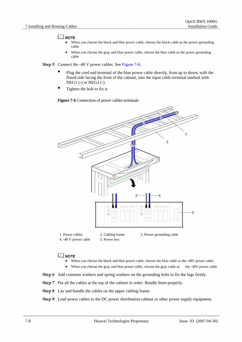
Step 5 Connect the -48 V power cables. See Figure 7-6. Plug the cord end terminal of the blue power cable directly, from up to down, with the
fluted side facing the front of the cabinet, into the input cable terminal marked with NEG1 (-) or NEG2 (-).
Tighten the bolt to fix it.
Figure 7-6 Connection of power cables terminals
1
2
3 4
5
1. Power cables 2. Cabling frame 3. Power grounding cable 4. -48 V power cable 5. Power box
When you choose the black and blue power cable, choose the blue cable as the -48V power cable. When you choose the gray and blue power cable, choose the gray cable as the -48V power cable
Step 6 Add common washers and spring washers on the grounding bolts to fix the lugs firmly.
Step 7 Put all the cables at the top of the cabinet in order. Bundle them properly.
Step 8 Lay and bundle the cables on the upper cabling frame.
Step 9 Lead power cables to the DC power distribution cabinet or other power supply equipment.
OptiX BWS 1600G Installation Guide 7 Installing and Routing Cables
Issue 03 (2007-04-30) Huawei Technologies Proprietary 7-9
Step 10 Lead the protection grounding cable to the protection grounding bar in the equipment room.
Step 11 Cut the slack of the cables. Make the lugs in compliance with the corresponding terminals. Finally fix the cables to corresponding terminals.
When you make the lugs on both ends of the protection grounding cable and the lug on the end of the power cable connected to DC power distribution cabinet, the lugs should hold the strands tightly, and are wrapped tightly by the plastic insulation tape, so as not to uncover the naked cables and the lug stems.
Step 12 Connect subrack power cables and HUB power cables. See Figure 7-4.
Step 13 Attach labels to the cables. Refer to Appendix B "Engineering Labels for Cables" for the way to paste labels and the information on them.
----End.
7.1.3 Procedure for Downward Cabling Purpose This procedure describes how to install and route the cabinet
power cables in downward cabling mode.
Tools /Materials Cross screwdriver, Power cable, Protection grounding cable Wire cutter, Wire stripper, Crimp tool
Prerequisites The office power supply is prepared. The voltage ranges from –38.4 V DC to –72 V DC.
Required/As needed Required
Install the PGND cable before you install the power cable.
Ensure that the power of the DC power distribution cabinet is shut off before you take any of the steps below.
If the cable is short, stop the cabling, and replace it with an appropriate one. Do not extend the cable by means of connecting or soldering.
Determine whether to use upward cabling mode or downward cabling mode according to the conditions in the equipment room. Upward cabling mode refers to Section 7.1.2 "Procedure for Upward Cabling".

7 Installing and Routing Cables OptiX BWS 1600G
Installation Guide
7-10 Huawei Technologies Proprietary Issue 03 (2007-04-30)
Step 1 Lay the power cables under the antistatic floor. Lead the end installed with cord end terminal to the bottom of the cabinet.
Step 2 Route power cable in the downward cabling mode. Lead the cables into the cabinet through the support and then the power cable hole on the
bottom of the cabinet. Lay them upward to the top of the cabinet along the signal cabling area at the right side
of the cabinet. Lead -48V power cables and power grounding cables to the position of input cable
terminal on the power distribution box through the space between the upper enclosure frame of the cabinet and the power distribution box.
Lead PGND cable to the grounding bolt through the cabling hole on the top of the cabinet.
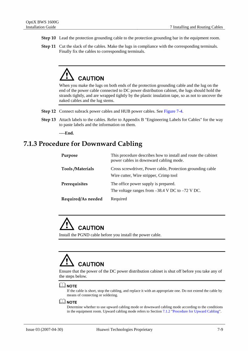
Step 3 Connect the lug of the green-yellow protection grounding cable to the grounding bolts at the top of the cabinet. See Figure 7-7.
Choose a way to install the protection grounding cable according to the specification of the lug and the amount of the grounding bolts at the top of the cabinet
If the lug is OT single-hole naked crimping connector, install the protection grounding cable as shown in Figure 7-7 (1), (2).
If the lug is OT dual-hole naked crimping connector, install the protection grounding cable as shown in Figure 7-7 (3), (4).
OptiX BWS 1600G Installation Guide 7 Installing and Routing Cables
Issue 03 (2007-04-30) Huawei Technologies Proprietary 7-11
Figure 7-7 Downward cabling for protection grounding cables
41
3
5 6
1 2
3 4
7 8
2
1. Signal cabling area 2. Subrack 3. Support 4. Protection grounding cable 5. OT single-hole naked crimping connector and two grounding bolts 6. OT dual-hole naked crimping connector and two grounding bolts 7. OT dual-hole naked crimping connector and one grounding bolt 8. OT single-hole naked crimping connector and one grounding bolt
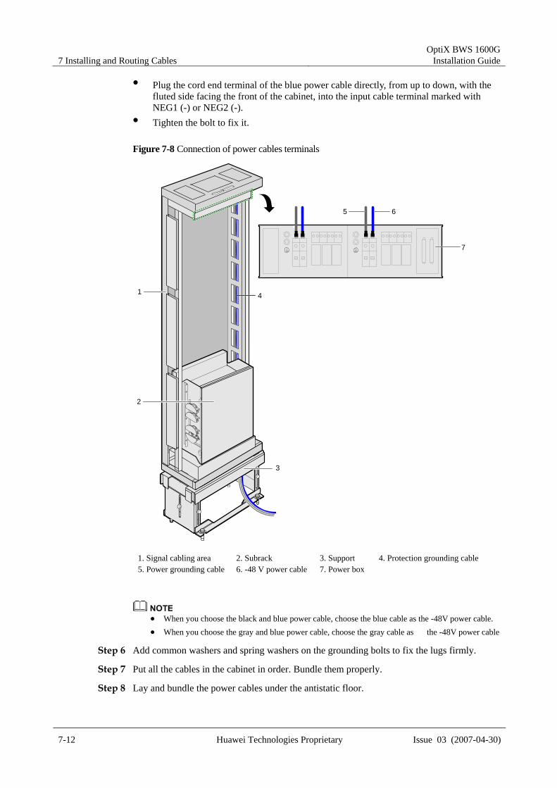
Step 4 Connect the power grounding cable. See Figure 7-8. Plug the cord end terminal of the black power cable directly, with the fluted side facing
the front of the cabinet, from up to down, into the input cable terminal marked with RTN1 (+) or RTN2 (+).
Tighten the bolt to fix it.
When you choose the black and blue power cable, choose the black cable as the power grounding
cable. When you choose the gray and blue power cable, choose the blue cable as the power grounding
cable.
Step 5 Connect the -48V power cable. See Figure 7-8.
7 Installing and Routing Cables OptiX BWS 1600G
Installation Guide
7-12 Huawei Technologies Proprietary Issue 03 (2007-04-30)
Plug the cord end terminal of the blue power cable directly, from up to down, with the fluted side facing the front of the cabinet, into the input cable terminal marked with NEG1 (-) or NEG2 (-).
Tighten the bolt to fix it.
Figure 7-8 Connection of power cables terminals
41
3
5 6
7
2
1. Signal cabling area 2. Subrack 3. Support 4. Protection grounding cable5. Power grounding cable 6. -48 V power cable 7. Power box
When you choose the black and blue power cable, choose the blue cable as the -48V power cable. When you choose the gray and blue power cable, choose the gray cable as the -48V power cable
Step 6 Add common washers and spring washers on the grounding bolts to fix the lugs firmly.
Step 7 Put all the cables in the cabinet in order. Bundle them properly.
Step 8 Lay and bundle the power cables under the antistatic floor.

OptiX BWS 1600G Installation Guide 7 Installing and Routing Cables
Issue 03 (2007-04-30) Huawei Technologies Proprietary 7-13
Step 9 Lead power cables and power grounding cables to the DC power distribution cabinet or other power supply equipment.
Step 10 Lead the protection grounding cable to the protection grounding bar in the equipment room.
Step 11 Cut the slack of the cables. Make the lugs in compliance with the corresponding terminals. Finally fix the cables to corresponding terminals.
When you make the lugs on both ends of the protection grounding cable and the lug on the end of the power cable connected to DC power distribution cabinet, the lugs should hold the strands tightly, and are wrapped tightly by the plastic insulation tape, so as not to uncover the naked cables and the lug stems.
Step 12 Connect subrack power cables and HUB power cables. See Figure 7-4.
Step 13 Attach labels to the cables. Refer to Appendix B "Engineering Labels for Cables" for the way to paste labels and the information on them.
----End.
7.1.4 Resistance Measurement before Power-Up Before you power up the equipment, please use multimeter to measure the resistance between the power (NEG(-)) and the power ground (RTN(+))/PGND on the left side and the right side respectively.
When the subrack power switches (SW1/SW2/SW3) are turned off, the resistance measured should be several kilo-ohms.
If the measured resistance is less than 20 ohms, it shows that the short circuit exists between the power and the power ground/protection ground. Make sure to power up the equipment after eliminating the faults.
7.2 Installing and Routing Alarm Cables This section describes how to install and route alarm cables.
7.2.1 Introduction to ALARM Interface and Cables
ALARM Interface In the power box, the PMU board implements alarm input, alarm output and alarm cascading functions. The ALARM on the PMU is an external alarm interface, used for alarm/Boolean value input/output between the cabinet and users’ centralized alarm system. Up to 16 Boolean values can be input to the cabinet, while four Boolean values can be output. Output Boolean values from different cabinets can be cascaded.

7 Installing and Routing Cables OptiX BWS 1600G
Installation Guide
7-14 Huawei Technologies Proprietary Issue 03 (2007-04-30)
The positions of the PMU and ALARM interface in the power box are shown in Figure 7-9.
Figure 7-9 ALARM interface
PDUPMU
RUN
AL MPO W ER IN
RTN(+) NEG(-)
2 0 A 2 0 A 2 0 A 2 A
O U T 1 O U T 2 O U T 3 AU X
O FF O FF
ONONON
O FF
SW 1 SW 2 SW 3
RUN
AL M
TEST
M U TE
ALAR M SER IAL
PMU
RUN
ALM
TEST
MUTE
ALARM SERIALPDU
RUN
AL MPO W ER IN
RTN(+) NEG(-)
2 0 A 2 0 A 2 0 A 2 A
O U T 1 O U T 2 O U T 3 AU X
O FF OFF
ONONON
O FF
SW 1 SW 2 SW 3 SW 3
Alarm Cables The alarm cables are shown in Figure 7-10:
X1 is a DB50 connector, inserted in the ALARM interface on the power box. W2 and W3 are alarm cascading/output cables, and X2 and X3 are DB9 connectors
(male) for realizing alarm signal cascading and output. W1 is an alarm input cable. X4 is a DB37 connector (female) for accessing external
alarm signals.
Figure 7-10 Alarm cables
X1
W2
W1
W3
X2
X4
X3
Alarm Input Transfer Cable When external alarms are input, a 10 m alarm input transfer cable (DB37 male connector at one end and the other end reserved) is required to be connected with the alarm input cable. The external alarm input transfer cable is shown in Figure 7-11.

OptiX BWS 1600G Installation Guide 7 Installing and Routing Cables
Issue 03 (2007-04-30) Huawei Technologies Proprietary 7-15
Figure 7-11 The alarm input transfer cable
10m
Pin.1
Pin.37
If no external alarm is input for centralized monitoring in this station, the alarm input transfer cable is not required and W1 alarm input cable is reserved.
Alarm Transfer Cable
If a number of cabinets are installed side by side, the alarms of the cabinets can be cascaded via an alarm transfer cable and then output to the centralized alarm system.
Since the cascading connectors of the alarm cables shown in Figure 7-10 are all DB9 male connectors, another transfer cable with the both ends being DB9 female connectors is required for cascading alarms. The alarm transfer cable is shown in Figure 7-12
Figure 7-12 Alarm transfer cable
W
Alarm Output Transfer Cable In the last cabinet for alarm cascading, alarm signals are output to the power distribution cabinet or the designated centralized alarm system in the equipment room via an alarm output transfer cable. One end of the alarm output transfer cable is DB9 female connector. It is connected to the cascading/output connector of the alarm cable as shown in Figure 7-10. The other end has no connector and is directly connected to the designated position through the core wire.

7 Installing and Routing Cables OptiX BWS 1600G
Installation Guide
7-16 Huawei Technologies Proprietary Issue 03 (2007-04-30)
7.2.2 Pin Assignment
Alarm Input Transfer Cable The reserved end of the alarm input transfer cable has signal wires in five different colors: BLUE (8 in total), GRAY (6 in total), PINK (6 in total), Green (6 in total) and Orange (6 in total). The signal wires in the same color distinguish themselves by the tiny square spots in different colors (RED and BLK) on the wires.
(1) The core wire with red tiny square spots is defined as signal wire, while the core wire with black tiny square spots is defined as ground. (2) Each "x" means that there is a group of one tiny square spot at intervals. (e.g. BLUE/REDxxx means that there is a group of three red square spots on a blue signal wire at intervals.)
The pin assignment of the alarm input transfer cable is shown in Table 7-1.
Table 7-1 Pin assignment of the external alarm input cable
Pin No.
Color and mark
Channel No.
Pin No. Color and mark Channel No.
Pin.1 PINK/ REDx Pin.17 GRN/ REDxx
Pin.2 PINK/ BLKx
1
Pin.18 GRN/ BLKxx
6
Pin.3 ORG/ REDx Pin.19 GRAY/ REDxx
Pin.4 ORG/ BLKx
2
Pin.20 GRAY/ BLKxx
13
Pin.5 BLUE/ REDx Pin.21 PINK/ REDxxx
Pin.6 BLUE/ BLKx
8
Pin.22 PINK/ BLKxxx
14
Pin.7 GRN/ REDx Pin.23 ORG/ REDxxx
Pin.8 GRN/ BLKx
9
Pin.24 ORG/ BLKxxx
12
Pin.9 GRAY/ REDx Pin.25 BLUE/ REDxxx
Pin.10 GRAY/ BLKx
3
Pin.26 BLUE/ BLKxxx
5
Pin.11 PINK/ REDxx Pin.27 GRN/ REDxxx
Pin.12 PINK/ BLKxx
10
Pin.28 GRN/ BLKxxx
11
Pin.13 ORG/ REDxx Pin.29 GRAY/ REDxxx
Pin.14 ORG/ BLKxx
4
Pin.30 GRAY/ BLKxxx
15
Pin.15 BLUE/ REDxx Pin.31 BLUE/ REDxxxx
Pin.16 BLUE/ BLKxx
7
Pin.32 BLUE/ BLKxxxx
16

OptiX BWS 1600G Installation Guide 7 Installing and Routing Cables
Issue 03 (2007-04-30) Huawei Technologies Proprietary 7-17
Alarm Output Transfer Cable The pin assignment of the alarm output cable is shown in Table 7-2.
Table 7-2 Alarm output cable connection relationship
Signal wire Color of core wire Output
Major alarm BLUE
Major alarm ground WHITE
Major alarm Boolean value
Critical alarm ORANGE
Critical alarm ground WHITE
Critical alarm Boolean value
Auxiliary alarm 1 GREEN
Auxiliary alarm 1 ground WHITE
Auxiliary alarm Boolean value 1
Auxiliary alarm 2 BROWN
Auxiliary alarm 2 ground WHITE
Auxiliary alarm Boolean value 2
7.2.3 Procedure for Installing Alarm Cables Purpose This procedure describes how to install alarm cables.
Tools /Materials Alarm cable Alarm input transfer cable Alarm cascading transfer cable Alarm output transfer cable
Prerequisites The monitoring system in the equipment room has been installed properly, with interfaces reserved for use.
Required/As needed Required
External alarm input includes environmental variables such as access control, smog, and so on. It is mainly to access various environment alarms in the equipment room for centralized monitoring. The user accesses the external alarm values directly. After the software judgment, the valid signals will be displayed at the NM.
The OptiX BWS 1600G equipment can provide 4 alarm outputs: one is for critical alarm, another one for major alarm interface, and the other two for auxiliary alarm Boolean value.
Step 1 One alarm cable is used for each cabinet.
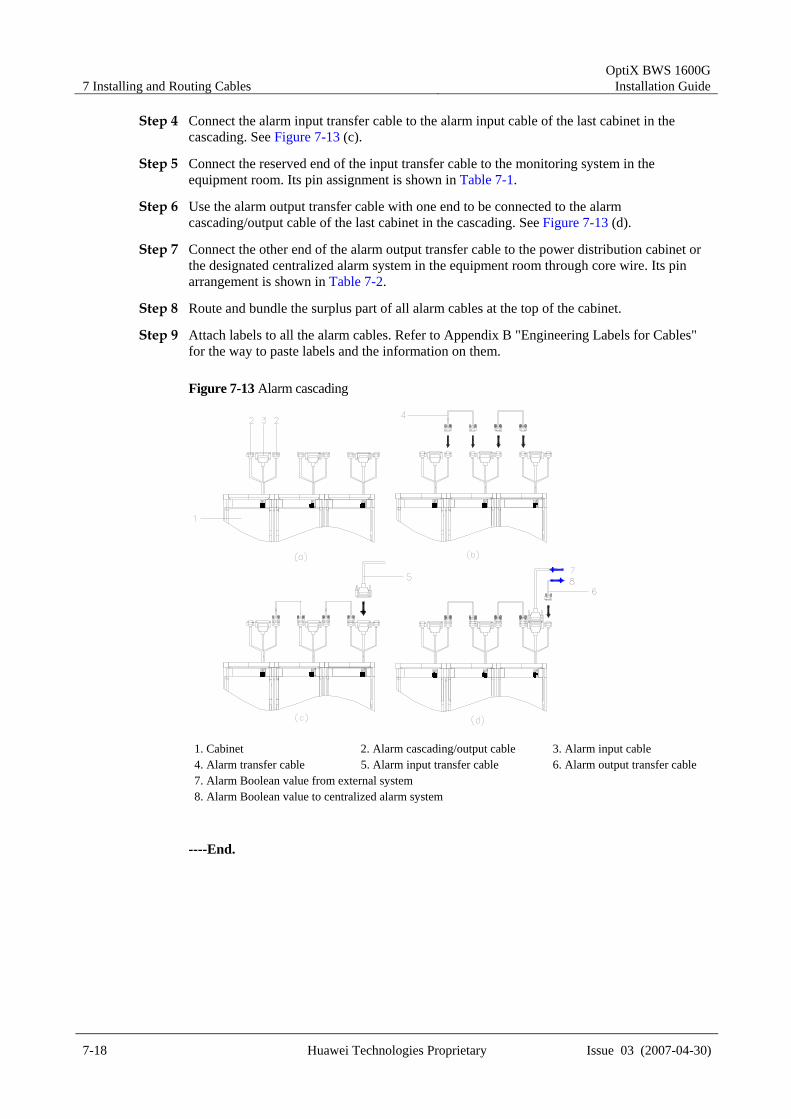
Step 2 Plug the DB50 connector of the alarm cable in the ALARM interface on the power box of the cabinet. See Figure 7-13 (a).
Step 3 Use the alarm transfer cable to connect the alarm cascading cables of adjacent cabinets to realize alarm cascading. See Figure 7-13 (b).
7 Installing and Routing Cables OptiX BWS 1600G
Installation Guide
7-18 Huawei Technologies Proprietary Issue 03 (2007-04-30)
Step 4 Connect the alarm input transfer cable to the alarm input cable of the last cabinet in the cascading. See Figure 7-13 (c).
Step 5 Connect the reserved end of the input transfer cable to the monitoring system in the equipment room. Its pin assignment is shown in Table 7-1.
Step 6 Use the alarm output transfer cable with one end to be connected to the alarm cascading/output cable of the last cabinet in the cascading. See Figure 7-13 (d).
Step 7 Connect the other end of the alarm output transfer cable to the power distribution cabinet or the designated centralized alarm system in the equipment room through core wire. Its pin arrangement is shown in Table 7-2.
Step 8 Route and bundle the surplus part of all alarm cables at the top of the cabinet.
Step 9 Attach labels to all the alarm cables. Refer to Appendix B "Engineering Labels for Cables" for the way to paste labels and the information on them.
Figure 7-13 Alarm cascading
1. Cabinet 2. Alarm cascading/output cable 3. Alarm input cable 4. Alarm transfer cable 5. Alarm input transfer cable 6. Alarm output transfer cable7. Alarm Boolean value from external system 8. Alarm Boolean value to centralized alarm system
----End.

OptiX BWS 1600G Installation Guide 7 Installing and Routing Cables
Issue 03 (2007-04-30) Huawei Technologies Proprietary 7-19
7.3 Installing and Routing Clock Cables 7.3.1 Introduction to Clock Interfaces
Each subrack of the OptiX BWS 1600G has 11 clock interfaces of three types, which are located in the interface area of the subrack, as shown in Figure 7-14.
Figure 7-14 Subrack interface area
PHONE 1
ETHERNET 1 ETHERNET 2 CLKIN CLKOUT OCU CLKIN1 2 1 2 3
3 4 5 6
PHONE 2
PHONE 3
F&f Serial 1 Serial 2 ALM F1 OAM
POWER1 POWER2
CLKIN CLKOUTOCU CLKIN
The functions of clock interfaces are as follows:
CLKIN 1~3: SMB socket, three external clock input interfaces CLKOUT 1~6: SMB socket, 6 clock output interfaces OCU CKLIN: SMB socket, providing 2 external clock source interfaces for the OCU
board.
7.3.2 Installation Procedure Determine the subrack to be connected with the clock cable according to the configuration requirements and the cabling mode according to the conditions in the equipment room.
Procedure for Upward Cabling Purpose This procedure describes how to install clock cables in upward
cabling mode.
Tools /Materials Clock cables
Prerequisites The BITS system in the equipment room has been installed properly, with interfaces reserved for use.
Required/As needed As needed
Step 1 Lead the clock cable into the cabinet from the left signal cable hole on the top of the cabinet.
Step 2 Lay the clock cable to the corresponding subrack along the signal cabling area on the left of the cabinet.

7 Installing and Routing Cables OptiX BWS 1600G
Installation Guide
7-20 Huawei Technologies Proprietary Issue 03 (2007-04-30)
Step 3 Lead the clock cable to the subrack interface area from the space at the left side of the subrack interface area. See Figure 7-15.
Figure 7-15 Routing of clock cables
Step 4 Plug the connector of the clock cable into the corresponding clock interface in the subrack interface area and tighten it properly.
Step 5 Lay the clock cable on the upward cabling frame and connect it to the corresponding BITS system in the equipment room.
Step 6 Bundle the clock cables and attach labels to them. Refer to Appendix B “Engineering Labels for Cables” for the way to paste labels and the information on them.
----End.
Procedure for Downward Cabling Purpose This procedure describes how to install clock cables in
downward cabling mode.
Tools /Materials Clock cables
Prerequisites The BITS system in the equipment room has been installed properly, with interfaces reserved for use.
Required/As needed As needed
Step 1 Pass the clock cable through the subrack, and lead it into the cabinet from the left signal cable hole on the bottom of the cabinet.
Step 2 Lay the clock cable to the corresponding subrack along the signal cabling area on the left of the cabinet.
Step 3 Lead the clock cable to the subrack interface area from the trough at the side of the subrack interface area. See Figure 7-16.

OptiX BWS 1600G Installation Guide 7 Installing and Routing Cables
Issue 03 (2007-04-30) Huawei Technologies Proprietary 7-21
Figure 7-16 Downward cabling
Step 4 Plug the connector of the clock cable into the corresponding clock interface in the subrack interface area and tighten it properly.
Step 5 Lay the clock cable under the ESD floor and connect it to the corresponding BITS system in the equipment room.
Step 6 Bundle the clock cables and attach labels to them. Refer to Appendix C “Engineering Labels for Cables” for the way to paste labels and the information on them.
----End.
7.4 Installing and Routing Network Cables 7.4.1 Connecting Network Cables
Each subrack of the OptiX BWS 1600G has two Ethernet interfaces, ETHERNET1 and ETHERNET2. They are at the upper left corner of the interface area of the subrack. See Figure 7-17.
Figure 7-17 Ethernet interfaces in the interface area of the subrack
PHONE 1
ETHERNET 1 ETHERNET 2 CLKIN CLKOUT OCU CLKIN1 2 1 2 3
3 4 5 6
PHONE 2
PHONE 3
F&f Serial 1 Serial 2 ALM F1 OAM
POWER1 POWER2
ETHERNET 1ETHERNET 2
7 Installing and Routing Cables OptiX BWS 1600G
Installation Guide
7-22 Huawei Technologies Proprietary Issue 03 (2007-04-30)
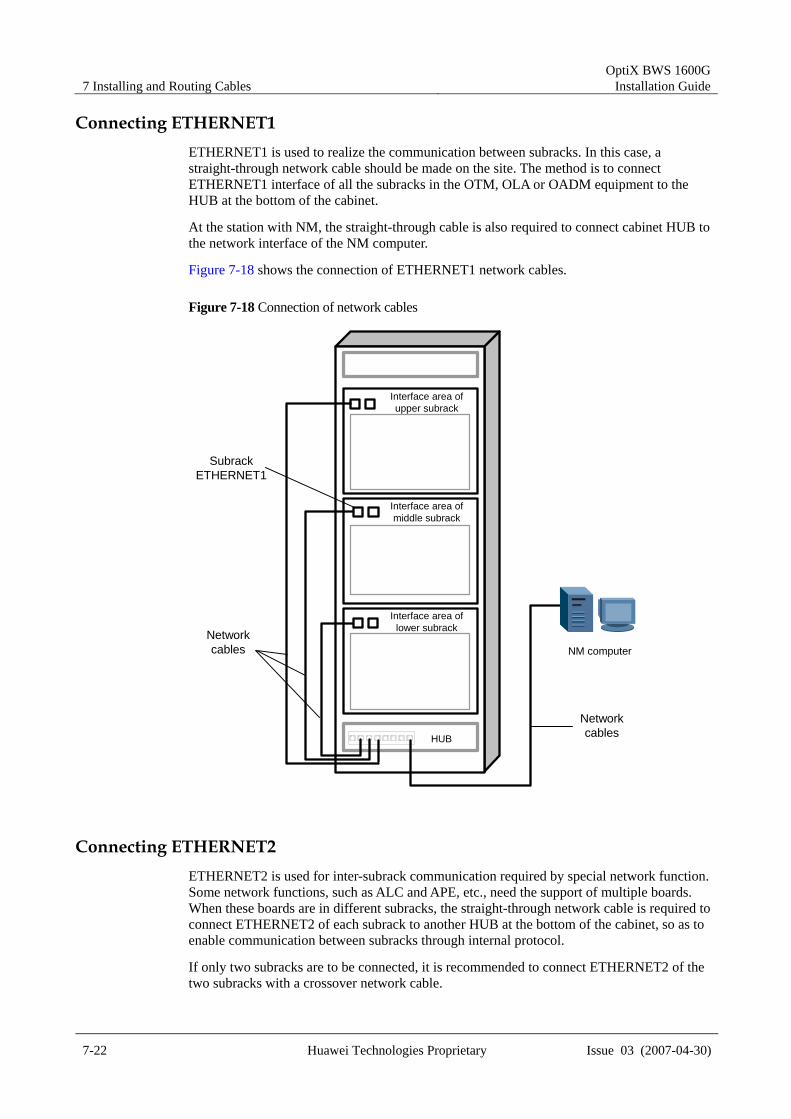
Connecting ETHERNET1 ETHERNET1 is used to realize the communication between subracks. In this case, a straight-through network cable should be made on the site. The method is to connect ETHERNET1 interface of all the subracks in the OTM, OLA or OADM equipment to the HUB at the bottom of the cabinet.
At the station with NM, the straight-through cable is also required to connect cabinet HUB to the network interface of the NM computer.
Figure 7-18 shows the connection of ETHERNET1 network cables.
Figure 7-18 Connection of network cables
NM computer
Interface area ofupper subrack
Interface area ofmiddle subrack
Interface area oflower subrack
SubrackETHERNET1
Networkcables
NetworkcablesHUB
Connecting ETHERNET2 ETHERNET2 is used for inter-subrack communication required by special network function. Some network functions, such as ALC and APE, etc., need the support of multiple boards. When these boards are in different subracks, the straight-through network cable is required to connect ETHERNET2 of each subrack to another HUB at the bottom of the cabinet, so as to enable communication between subracks through internal protocol.
If only two subracks are to be connected, it is recommended to connect ETHERNET2 of the two subracks with a crossover network cable.

OptiX BWS 1600G Installation Guide 7 Installing and Routing Cables
Issue 03 (2007-04-30) Huawei Technologies Proprietary 7-23
ETHERNET1 and ETHERNET2 in the subrack interface area cannot be substituted for
each other. Port 1 and UPLINK port of the HUB cannot be used simultaneously
7.4.2 Core Wire Colors of Network Cables The structure of the network cable is an 8-core category-5 twisted pair cable with RJ-45 connectors on both ends. See Figure 7-19.
Figure 7-19 Network cable
123
68
123
68
W
X1 X2
The network cable includes the straight-through cable and crossover cable. The straight-through cable and the cross-over cable differ in connection relationship but have the same structure.
Both the straight-through and crossover network cables adopt the RJ45 connector. The connector pins are numbered as follows: Turn the pin side upward, hold the cable close to your side, and the pins are numbered 1~8 from left to right. See Figure 7-20.
Figure 7-20 Pin numbering of RJ45 connector
PIN #8
PIN #1

7 Installing and Routing Cables OptiX BWS 1600G
Installation Guide
7-24 Huawei Technologies Proprietary Issue 03 (2007-04-30)
Straight-through Network Cable The connection is shown in Figure 7-21. The core wire colors of two connectors of the straight-through network cable are shown in Table 7-3.
Figure 7-21 Connection relationship of straight-through network cables
12345678
12345678
Table 7-3 Core wire colors of two connectors of the straight-through network cable
Color of core wire Network cable connector 1 2 3 4 5 6 7 8
Head end White and orange
Orange White and green
Blue White and blue
Green White and brown
Brown
Tail end White and orange
Orange White and green
Blue White and blue
Green White and brown
Brown
Crossover Network Cable The connection relationship of crossover network cables is shown in Figure 7-22. The core wire colors of two connectors of the crossover network cable are shown in Table 7-4.
Figure 7-22 Connection relationship of crossover network cables
12345678
12345678

OptiX BWS 1600G Installation Guide 7 Installing and Routing Cables
Issue 03 (2007-04-30) Huawei Technologies Proprietary 7-25
Table 7-4 Core wire colors of two connectors of the crossover network cable
Color of core wire Network cable connector 1 2 3 4 5 6 7 8
Head end White and orange
Orange White and green
Blue White and blue
Green White and brown
Brown
Tail end White and green
Green White and orange
Blue White and blue
Orange White and brown
Brown
Usually, there are four pairs of twisted pair cables in the 8-core network cable. Pins 1 and 2 of RJ-45 connector should share a pair of twisted pair cables. Pins 3 and 6 should share another pair of twisted pair cables. Otherwise, the signal transmission distance will be greatly limited.
7.4.3 Installing Cables Between the Subrack and HUB Purpose This procedure describes how to install network cables.
Tools /Materials Crimping pliers with crystal head, Ethernet cables Cable ties
Prerequisites The subracks and HUB have been installed.
Required/As needed Required
The connection of network cables of ETHERNET1 is taken as an example. That of ETHERNET2 is basically the same.
Step 1 Cut out a network cable according to the distance between ETHERNET1 of each subrack and the HUB at the bottom of the cabinet.
Step 2 Make RJ-45 connector at the both sides of all network cables. For the core wire colors of straight-through cable, see Section 7.4.2 in this chapter.
Step 3 Lay the network cables along the signal cabling area on the left of the cabinet.
Step 4 Lay one end to the corresponding subrack interface area.
Step 5 Lay the other end to the HUB at the bottom of the cabinet.
Step 6 Lead the network cable into the subrack interface area along the trough at the side of the subrack interface area.
Step 7 Insert the network cable into ETHERNET1.
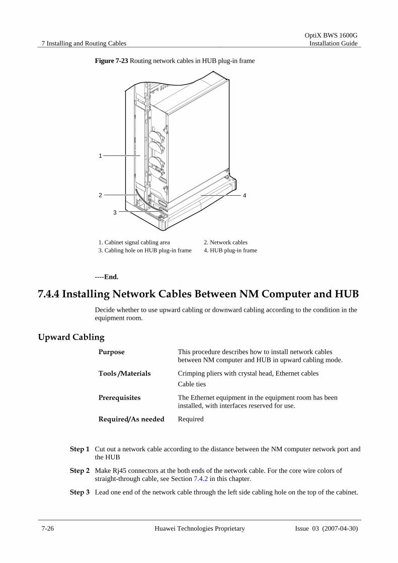
Step 8 Lead the other end of the network cable into the subrack from the Hub plug-in frame. Insert it into the corresponding HUB port. See Figure 7-23.
7 Installing and Routing Cables OptiX BWS 1600G
Installation Guide
7-26 Huawei Technologies Proprietary Issue 03 (2007-04-30)
Figure 7-23 Routing network cables in HUB plug-in frame
1
2
3
4
1. Cabinet signal cabling area 2. Network cables 3. Cabling hole on HUB plug-in frame 4. HUB plug-in frame
----End.
7.4.4 Installing Network Cables Between NM Computer and HUB Decide whether to use upward cabling or downward cabling according to the condition in the equipment room.
Upward Cabling Purpose This procedure describes how to install network cables
between NM computer and HUB in upward cabling mode.
Tools /Materials Crimping pliers with crystal head, Ethernet cables Cable ties
Prerequisites The Ethernet equipment in the equipment room has been installed, with interfaces reserved for use.
Required/As needed Required
Step 1 Cut out a network cable according to the distance between the NM computer network port and the HUB
Step 2 Make Rj45 connectors at the both ends of the network cable. For the core wire colors of straight-through cable, see Section 7.4.2 in this chapter.
Step 3 Lead one end of the network cable through the left side cabling hole on the top of the cabinet.

OptiX BWS 1600G Installation Guide 7 Installing and Routing Cables
Issue 03 (2007-04-30) Huawei Technologies Proprietary 7-27
Step 4 Route the cables to the HUB at the cabinet bottom along the signal cabling area on the left side of the cabinet.
Step 5 Lead the network cable into the HUB plug-in frame from the Cabling hole. Insert it into the corresponding HUB port. See Figure 7-23.
Step 6 Lay the network cable on the upper cabling frame.
Step 7 Lead the other end of the network cable to the network interface of the NM computer in the equipment room.
Step 8 Bundle the network cables. Attach labels to them. Refer to Appendix B "Engineering Labels for Cables".
----End.
Downward Cabling Purpose This procedure describes how to install network cables between
NM computer and HUB in downward cabling mode.
Tools /Materials Crimping pliers with crystal head, Ethernet cables Cable ties
Prerequisites The Ethernet equipment in the equipment room has been installed, with interfaces reserved for use.
Required/As needed Required
Step 1 Cut out a network cable according to the distance between the NM computer and the HUB.
Step 2 Make RJ45 connectors at the both sides of the network cable. For the core wire colors of straight-through cable, see Section 7.4.2 in this chapter.
Step 3 Through the support, lead one end of the network cable through the left side cabling hole at the bottom of the cabinet.
Step 4 Lead the network cable into the HUB plug-in frame from the Cabling hole. Insert it into the corresponding HUB port. See Figure 7-23.
Step 5 Lay the network cable under the antistatic floor.
Step 6 Lead the other end of the network cable to the network interface of the NM computer in the equipment room.
Step 7 Bundle the network cables. Attach labels to them. Refer to Appendix B "Engineering Labels for Cables".
----End


