
installing and configuring Internet Protocol Telefphony Card.pdf
52
Installing and Configuring Internet Protocol Telephony Card August 2011
-
Upload
ricardo-chacon -
Category
Documents
-
view
118 -
download
5
Transcript of installing and configuring Internet Protocol Telefphony Card.pdf
Installing and Configuring InternetProtocol Telephony Card
August 2011

© 2011 Avaya Inc.
All Rights Reserved.
Notice
While reasonable efforts have been made to ensure that theinformation in this document is complete and accurate at the time ofprinting, Avaya assumes no liability for any errors. Avaya reserves theright to make changes and corrections to the information in thisdocument without the obligation to notify any person or organization ofsuch changes.
Documentation disclaimer
“Documentation” means information published by Avaya in varyingmediums which may include product information, operating instructionsand performance specifications that Avaya generally makes availableto users of its products. Documentation does not include marketingmaterials. Avaya shall not be responsible for any modifications,additions, or deletions to the original published version ofdocumentation unless such modifications, additions, or deletions wereperformed by Avaya. End User agrees to indemnify and hold harmlessAvaya, Avaya's agents, servants and employees against all claims,lawsuits, demands and judgments arising out of, or in connection with,subsequent modifications, additions or deletions to this documentation,to the extent made by End User.
Link disclaimer
Avaya is not responsible for the contents or reliability of any linked Websites referenced within this site or documentation provided by Avaya.Avaya is not responsible for the accuracy of any information, statementor content provided on these sites and does not necessarily endorsethe products, services, or information described or offered within them.Avaya does not guarantee that these links will work all the time and hasno control over the availability of the linked pages.
Warranty
Avaya provides a limited warranty on its Hardware and Software(“Product(s)”). Refer to your sales agreement to establish the terms ofthe limited warranty. In addition, Avaya’s standard warranty language,as well as information regarding support for this Product while underwarranty is available to Avaya customers and other parties through theAvaya Support Web site: http://support.avaya.com. Please note that ifyou acquired the Product(s) from an authorized Avaya reseller outsideof the United States and Canada, the warranty is provided to you bysaid Avaya reseller and not by Avaya.
Licenses
THE SOFTWARE LICENSE TERMS AVAILABLE ON THE AVAYAWEBSITE, HTTP://SUPPORT.AVAYA.COM/LICENSEINFO/ AREAPPLICABLE TO ANYONE WHO DOWNLOADS, USES AND/ORINSTALLS AVAYA SOFTWARE, PURCHASED FROM AVAYA INC.,ANY AVAYA AFFILIATE, OR AN AUTHORIZED AVAYA RESELLER(AS APPLICABLE) UNDER A COMMERCIAL AGREEMENT WITHAVAYA OR AN AUTHORIZED AVAYA RESELLER. UNLESSOTHERWISE AGREED TO BY AVAYA IN WRITING, AVAYA DOESNOT EXTEND THIS LICENSE IF THE SOFTWARE WAS OBTAINEDFROM ANYONE OTHER THAN AVAYA, AN AVAYA AFFILIATE OR ANAVAYA AUTHORIZED RESELLER; AVAYA RESERVES THE RIGHTTO TAKE LEGAL ACTION AGAINST YOU AND ANYONE ELSEUSING OR SELLING THE SOFTWARE WITHOUT A LICENSE. BYINSTALLING, DOWNLOADING OR USING THE SOFTWARE, ORAUTHORIZING OTHERS TO DO SO, YOU, ON BEHALF OFYOURSELF AND THE ENTITY FOR WHOM YOU ARE INSTALLING,DOWNLOADING OR USING THE SOFTWARE (HEREINAFTERREFERRED TO INTERCHANGEABLY AS “YOU” AND “END USER”),AGREE TO THESE TERMS AND CONDITIONS AND CREATE ABINDING CONTRACT BETWEEN YOU AND AVAYA INC. OR THEAPPLICABLE AVAYA AFFILIATE ( “AVAYA”).
Avaya grants End User a license within the scope of the license typesdescribed below. The applicable number of licenses and units ofcapacity for which the license is granted will be one (1), unless a
different number of licenses or units of capacity is specified in theDocumentation or other materials available to End User. “DesignatedProcessor” means a single stand-alone computing device. “Server”means a Designated Processor that hosts a software application to beaccessed by multiple users. “Software” means the computer programsin object code, originally licensed by Avaya and ultimately utilized byEnd User, whether as stand-alone Products or pre-installed onHardware. “Hardware” means the standard hardware originally sold byAvaya and ultimately utilized by End User.
Copyright
Except where expressly stated otherwise, no use should be made ofmaterials on this site, the Documentation, Software, or Hardwareprovided by Avaya. All content on this site, the documentation and theProduct provided by Avaya including the selection, arrangement anddesign of the content is owned either by Avaya or its licensors and isprotected by copyright and other intellectual property laws including thesui generis rights relating to the protection of databases. You may notmodify, copy, reproduce, republish, upload, post, transmit or distributein any way any content, in whole or in part, including any code andsoftware unless expressly authorized by Avaya. Unauthorizedreproduction, transmission, dissemination, storage, and or use withoutthe express written consent of Avaya can be a criminal, as well as acivil offense under the applicable law.
Third-party components
Certain software programs or portions thereof included in the Productmay contain software distributed under third party agreements (“ThirdParty Components”), which may contain terms that expand or limitrights to use certain portions of the Product (“Third Party Terms”).Information regarding distributed Linux OS source code (for thoseProducts that have distributed the Linux OS source code), andidentifying the copyright holders of the Third Party Components and theThird Party Terms that apply to them is available on the Avaya SupportWeb site: http://support.avaya.com/Copyright.
Preventing Toll Fraud
“Toll fraud” is the unauthorized use of your telecommunications systemby an unauthorized party (for example, a person who is not a corporateemployee, agent, subcontractor, or is not working on your company'sbehalf). Be aware that there can be a risk of Toll Fraud associated withyour system and that, if Toll Fraud occurs, it can result in substantialadditional charges for your telecommunications services.
Avaya Toll Fraud Intervention
If you suspect that you are being victimized by Toll Fraud and you needtechnical assistance or support, call Technical Service Center TollFraud Intervention Hotline at +1-800-643-2353 for the United Statesand Canada. For additional support telephone numbers, see the AvayaSupport Web site: http://support.avaya.com. Suspected securityvulnerabilities with Avaya products should be reported to Avaya bysending mail to: [email protected].
Trademarks
Avaya, the Avaya logo, Avaya one-X® Portal, Communication Manager,Application Enablement Services, Modular Messaging, andConferencing are either registered trademarks or trademarks of AvayaInc. in the United States of America and/or other jurisdictions.
All non-Avaya trademarks are the property of their respective owners,and “Linux” is a registered trademark of Linus Torvalds.
Downloading Documentation
For the most current versions of Documentation, see the AvayaSupport Web site: http://support.avaya.com.
Contact Avaya Support
Avaya provides a telephone number for you to use to report problemsor to ask questions about your Product. The support telephone number
2 Installing and Configuring Internet Protocol Telephony Card August 2011Comments? [email protected]

is 1-800-242-2121 in the United States. For additional supporttelephone numbers, see the Avaya Web site: http://support.avaya.com.
Installing and Configuring Internet Protocol Telephony Card August 2011 3

4 Installing and Configuring Internet Protocol Telephony Card August 2011Comments? [email protected]

Contents
Chapter 1: Overview of Proactive Contact PG230 Internet Protocol Telephony Card. 7Components and interfaces...................................................................................................................... 7Functions of IPTC..................................................................................................................................... 8Ethernet Ports........................................................................................................................................... 9IPTC front panel LED indications.............................................................................................................. 9Hot plug-in................................................................................................................................................. 11Using IPTC (on PG230RM, PG230, 5 foot cabinets, or any system that has been upgraded to the ENBC) 11
Chapter 2: ENBC software version matrix........................................................................ 13Switch Component compatibility with various software releases.............................................................. 13
Chapter 3: Upgrading to ENBC Generic v18.1................................................................. 15Upgrading the configuration for Software Reference Kit ENBC generic option 18.x.x............................. 15Taking a backup of the Switch Database.................................................................................................. 16Copying ENBC Generic software from CD to Dialer................................................................................. 17Shutting down the Switch.......................................................................................................................... 18Upgrading the ENBC software.................................................................................................................. 19
Turning on the Switch and running the Installation Utilities.............................................................. 19Loading the ENBC software on the hard drive................................................................................. 21Upgrading the ENBC Generic software............................................................................................ 24Configuring the Ethernet / NFS Interface......................................................................................... 25Installing ENBC ISDN/PRI option..................................................................................................... 27Restoring the Switch Database........................................................................................................ 28Terminating the Installation............................................................................................................... 29
Chapter 4: Configuring IPTC (on PG230RM, PG230, 5 foot cabinets, or any systemthat has been upgraded to the ENBC).............................................................................. 31
Configuring the IPTC................................................................................................................................. 31Adding a card in the PG230RM........................................................................................................ 32Activating the card............................................................................................................................ 33Changing the state of the card to Out Of Service............................................................................. 34Deleting a card from the PG230RM................................................................................................. 35
Configuring the IPTC in PG230RM........................................................................................................... 37Configuring the IP Signaling group........................................................................................................... 38Diagnostic for IPTC................................................................................................................................... 40
Chapter 5: Configuring Communication Manager for IPTC............................................ 43Using IPTC with Communication Manager............................................................................................... 43Adding the IP codec set............................................................................................................................ 43Adding the IP network region.................................................................................................................... 44Creating a signaling-group........................................................................................................................ 45Creating a Trunk group on Communication Manager............................................................................... 48
Index..................................................................................................................................... 51
Installing and Configuring Internet Protocol Telephony Card August 2011 5

6 Installing and Configuring Internet Protocol Telephony Card August 2011
Chapter 1: Overview of Proactive ContactPG230 Internet ProtocolTelephony Card
The Internet Protocol Telephony Card (IPTC) is RoHS compliant and includes lead-free components. TheIPTC supports H.323 connections from the public network and connections between Proactive Contactand other switches such as Communication Manager. This includes connections for Agents, InboundLines for Intelligent Call Blending, and Transfers.
New PG230RM systems support 128 IP ports per card up to a total of 12 cards for a total port capacity of1,410 IP ports. Older PG230 systems require a power supply upgrade to support a full load of 12 IPcards.
You cannot upgrade the power supplies of non-PG230RM systems, for example, Large Cabinet systems.These systems support a maximum of 6 IP cards for a total capacity of 768 IP ports. The number of IPTCcards is dependant on the number of other +5v cards also configured.
Note:To manage the IPTC, use the ENBC administration and maintenance interface on PG230 and not theProactive Contact software.
With the new H.323 capability, you can connect directly to other switches or to a public data network overa single network connection, such as LAN, WAN, and VPN. With a direct connection, you eliminate all theT1/E1 span cables, connectors, and other support hardware required at present. Alternatively, since theswitch retains all the existing PSTN capabilities, you can make some connections over IP and otherconnections over PSTN trunks.
The IPTC provides IP connectivity to the PG230RM. The details of the IPTC protocol are hidden from theProactive Contact application as with other port cards. The H.323 signaling stack and media processingare both resident on the card. Proactive Contact refers to the ports on the IPTC using the TDM timeslots.Existing host interface commands used for ISDN ports are used to establish calls on the IPTC. Theprotocol between the ENBC and the IPTC on the communication bus utilizes existing messages wherepossible and adds new messages when necessary.
Components and interfacesThe IPTC connects to the backplane of the Digital Switch Cardfile and provides IP connectivitycapabilities to the PG230RM. The Enhanced Network Bus Controller (ENBC) manages and
Installing and Configuring Internet Protocol Telephony Card August 2011 7
configures all of the cards on the backplane and communicates to the system controller runningthe Proactive Contact software. The ENBC communicates with the IPTC over theCommunications Bus for configuration at startup. The IPTC uses the TDM bus to transmit andreceive voice data to and from the DSP2 card, LPVC2, and other trunk and line cards. You caninsert the IPTC in any slot position from 3 through 20 of the plane though 3 through 6 arenormally used for services cards. Multiple IPTC cards can be on the backplane with the limitingfactor being the full utilization of the 2048 time slots and power supply of +5V. The backplanehas three connectors for each card. J1 of the backplane provides power to the IPTC. J2 is theprimary bus with cards that communicate with each other over two TDM busses,communications bus and call setup bus. J3 provides I/O to external connections, such as aLAN or another Ethernet bus as in the case of the IPTC.
IPv6 considerationsCurrently, the IPTC does not support IPv6. The architecture does not prevent theimplementation of IPv6 at a later date.
Internal or private networksGeneric endpoints are supported but must be managed by and entity such as CM. Privatenetworks support generic H323 endpoints but only through H.323 IP trunks.
Public networksThe IPTC uses a 100-Mbps full duplex Ethernet connection to connect to the corporate LAN.With this connection, IPTC can transmit and receive all internet traffic, such as RTP, RTCP,ARP, ICMP, H.323, FTP, and SNMP.
EndpointsThe IPTC provides a connection for generic H.323 endpoints but only through H.323 IP trunks.Connections to the CM are through IP H.323 tie trunks.
AdjuntsAdjuncts do not undergo changes when you add the IPTC to Proactive Contact withPG230RM.
Network management and administrationThe IPTC does not provide network management or administration capabilities.
Functions of IPTCThe IPTC handles all H.323 functions, including security, Quality of Service (QoS), and allbearer channel processing functions. The bearer channel processing functions include jitterbuffers, codec functions G.711 and G.729, DTMF detection regeneration, silence suppression,packet loss, echo cancellation, and gain control.
IP telephony environmentThe IPTC provides additional capability to the Proactive Contact system. Using the IPTC,Proactive Contact can operate in several scenarios. Many call center configurations today use
Overview of Proactive Contact PG230 Internet Protocol Telephony Card
8 Installing and Configuring Internet Protocol Telephony Card August 2011Comments? [email protected]

a PBX in conjunction with Proactive Contact. For those applications, the tie trunks may nowbe over the LAN. If the call center is distributed, the remote call centers can connect toProactive Contact through the WAN using the IPTC. The remote call center might be a smallPBX or an agent working in a virtual office.Proactive Contact with PG230RM can also use anIP connection to the Central Office (CO) where that option is available. As many offices beginto exploit the features of an IP-only office, call centers can use IP phones that the IPTC canconnect to through an intermediate PBX. You can use any combination of these features alongwith analog phones, headsets, and traditional PCM trunks.
Note:IP phones cannot be connected directly to the IPTC.
Ethernet PortsThe IPTC supports one 100 BaseTX Ethernet interfaces for carrying VoIP bearer and controldata. The Ethernet ports are available at the backpanel of PG230RM.
Note:The current version of the IPTC only has Ethernet Port 1 enabled. Connect the Ethernetcable to Port 1. Ethernet Port 2 is not active.
Ethernet LEDsThe LEDs of the Ethernet ports are dual colored, green and yellow. The LEDs indicate thefollowing:
• LED1: A solid green color indicates that the port is connected.• LED2: A blinking yellow color indicates 10-Mbps activity.• LED3: A blinking green color indicates 100-Mbps activity.
IPTC front panel LED indicationsThe IPTC provides one Services interface through the front faceplate and five LEDs. The red,yellow, and green LEDs indicate the maintenance and diagnostic status of IPTC.
The following table describes the operation of the various LEDs.
Ethernet Ports
Installing and Configuring Internet Protocol Telephony Card August 2011 9

Red LED YellowLED
GreenLED
Card status
OFF OFF OFF Card Active;Normal operation
OFF OFF ON Waiting for ENBC to initialize
OFF ON ON Waiting for firmware to download
OFF ON OFF No Flash: Remote (yellow) alarm detectedFlashing: ENBC not polling
ON ON OFF No valid IP connection
ON OFF OFF 1 Flash: RAM test failure2 Flashes: FIFO test failure4 Flashes: Unexpected interruption
ON OFF ON Communication bus failure
ON ON ON No flash: Self-test in progressFlashing: Waiting for processor activation
Overview of Proactive Contact PG230 Internet Protocol Telephony Card
10 Installing and Configuring Internet Protocol Telephony Card August 2011Comments? [email protected]

Hot plug-inThe IPTC can be plugged in to a system that is switched on and operational without causingany undesirable effects to that system.
Note:You must wear an anti-static strap when inserting or removing a card from the PG230RM toavoid a static discharge.
Warning:When you insert a card in a live dialing system, the card insertion can cause the switch toreboot. You must replace or insert the card when the dialer is not in use. Avaya is notresponsible for the switch reboot or if the switch is out of service when adding or removingthe card in the PG230RM.
Using IPTC (on PG230RM, PG230, 5 foot cabinets, or anysystem that has been upgraded to the ENBC)
Before you beginYou must upgrade the ENBC firmware (to version 18.1) present in the PG230 switch to be ableto use the IPTC. After upgrading the ENBC to version 18.1, when you plug in the IPTC, theENBC detects the IPTC and displays the related card configuration screen on theadministration console.
Hot plug-in
Installing and Configuring Internet Protocol Telephony Card August 2011 11

Overview of Proactive Contact PG230 Internet Protocol Telephony Card
12 Installing and Configuring Internet Protocol Telephony Card August 2011Comments? [email protected]

Chapter 2: ENBC software version matrix
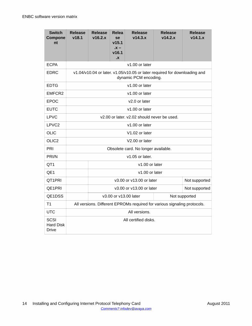
Switch Component compatibility with various softwarereleases
This sheet contains a list of various types of cards that are used in switch component and thecompatible firmware.
SwitchCompone
nt
Releasev18.1
Releasev16.2.x
Release
v15.1.x –
v16.1.x
Releasev14.3.x
Releasev14.2.x
Releasev14.1.x
ENBCEPROMS
V17.0.x, v15.2.x, or v14.1x
IPTC V1.10 orlater
Not supported
QDTC2 1.00 or later Not supported
4xT1 Not supported
4xE1 Not supported
DCC All versions. Different EPROMs required for A-law countries.
DDC v1.00 or later. v1.02/v10.02 required for downloading and dynamicPCM encoding.
DSP2 1.00 or later Not supported
DTG All versions. EPROMs and PALs vary for each country.
E1-CAS All versions.
E1-PRI v1.02 or later
E&M (4-wire)
All versions
ECC v1.00/v10.00 or later. v1.02/v10.02 required for downloading and dynamic PCMencoding.
Installing and Configuring Internet Protocol Telephony Card August 2011 13
SwitchCompone
nt
Releasev18.1
Releasev16.2.x
Release
v15.1.x –
v16.1.x
Releasev14.3.x
Releasev14.2.x
Releasev14.1.x
ECPA v1.00 or later
EDRC v1.04/v10.04 or later. v1.05/v10.05 or later required for downloading anddynamic PCM encoding.
EDTG v1.00 or later
EMFCR2 v1.00 or later
EPOC v2.0 or later
EUTC v1.00 or later
LPVC v2.00 or later. v2.02 should never be used.
LPVC2 v1.00 or later
OLIC V1.02 or later
OLIC2 V2.00 or later
PRI Obsolete card. No longer available.
PRI/N v1.05 or later.
QT1 v1.00 or later
QE1 v1.00 or later
QT1PRI v3.00 or v13.00 or later Not supported
QE1PRI v3.00 or v13.00 or later Not supported
QE1DSS v3.00 or v13.00 later Not supported
T1 All versions. Different EPROMs required for various signaling protocols.
UTC All versions.
SCSIHard DiskDrive
All certified disks.
ENBC software version matrix
14 Installing and Configuring Internet Protocol Telephony Card August 2011Comments? [email protected]

Chapter 3: Upgrading to ENBC Genericv18.1
Upgrading the configuration for Software Reference KitENBC generic option 18.x.x
An upgrade of the Digital Switch to release 18.x.x of the generic software for the EnhancedNetwork Bus Card (ENBC) implies that all components in the switch subrack must becompatible with this release. Check all firmware (EPROM) versions in Switch Componentcompatibility with various software releases on page 13 section.
Note:If this is an incremental upgrade of a system running ENBC Generic 16.1 Rev-1 (16.1.1),delete the database files card.tbl, port.tbl, resgroup.tbl, and nfascnfg.tbl and reboot theswitch to create blank versions of these files. Manually reenter the customer database toclean the database of a corruption introduced in 16.1 Rev 1. Create a file named“clean161.txt” and place the file in the c:/ directory to mark the system as clean. You cannotupgrade to 16.1 Rev 2 (16.1.2) or later until you complete these actions. An upgrade to 16.1Rev 2 (16.1.2) or later is not possible until these actions are completed. To clean a corrupt16.1.1 database, refer to PSN001471u.
Before you beginBefore initiating an upgrade, determine that the following items are present:
• ENBC I/O Transition Module (12466-03)• ENBC Card Assembly (12446-02)• SRK ENBC Generic 18.x (700472731)• 3.5 inch filler panel (30990-02)• Active NFS Mount to cpu1 for creating database backup
Procedure
1. Copy the ENBC Generic software from Disc to Dialer. See #unique_11.
2. Take a backup of the Switch database. See Taking a backup of the SwitchDatabase on page 16
3. Shut down the switch. See Shutting down the Switch on page 18.
Installing and Configuring Internet Protocol Telephony Card August 2011 15

4. Upgrade the ENBC software. See Upgrading the ENBC Generic software onpage 24.
5. Configure the IPTC. See Configuring the IPTC on page 31.
6. When the switch restarts and all other switch configuration changes (if any) arecompleted, repeat Step 2 Taking a backup of the Switch Database on page 16 totake a backup of the latest database.
ResultYou have successfully updated the ENBC generic software.
Taking a backup of the Switch DatabaseBefore upgrading the switch software or hardware, take a backup of the database. You canuse this backup to restore the database if an upgrade fails. Where a new ENBC TransitionModule is installed, use this backup to install the database on the new hard disk drive.
About this taskProcedure
1. On the Digital Switch log-in screen, type the user ID and password for the switchadministrator and press Enter. At the Administrator Main Menu Generic versionRevision 16.2.x, the system displays the following options.A D M I N I S T R A T O R M A I N M E N U
Generic Version.Revision 16.2.x
A) Data Base Administration Menu
B) System Configuration Menu
C) Maintenance Menu
D) Diagnostics Menu
Enter Selection: _2. Type C and press Enter to select the Maintenance Menu option.
3. In Maintenance Menu, type B and press Enter to select Disk Utilities menu.
4. Insert a DOS-formatted, 3-½” DSHD (1.44MB) disk into the floppy drive.
5. Type E and press Enter to select the Database Store menu.
6. In the OK To Store Database From C: To A: <Y/N>? message, type Y andpress Enter.
Upgrading to ENBC Generic v18.1
16 Installing and Configuring Internet Protocol Telephony Card August 2011Comments? [email protected]
7. When the backup is complete, press Ctrl+X key to return to the Disk Utilitiesmenu.
8. Remove the backup floppy disk from the floppy drive.
9. Press the Ctrl+G key to return to the Administrator Main menu.
10. Type B and press Enter to select the System Configuration Menu.
11. In the System Configuration Menu, type I and press Enter to select the NetworkConfiguration option.
12. Manually record the Internet Address and all Client and Remote NFS Serverconfiguration information (if used). You need this information in Step 9 for LoadingENBC Generic Software on to Hard Disk.
13. Press the Ctrl+G key to return to the Administrator Main menu.
ResultYou have completed the backup of the Switch Database.
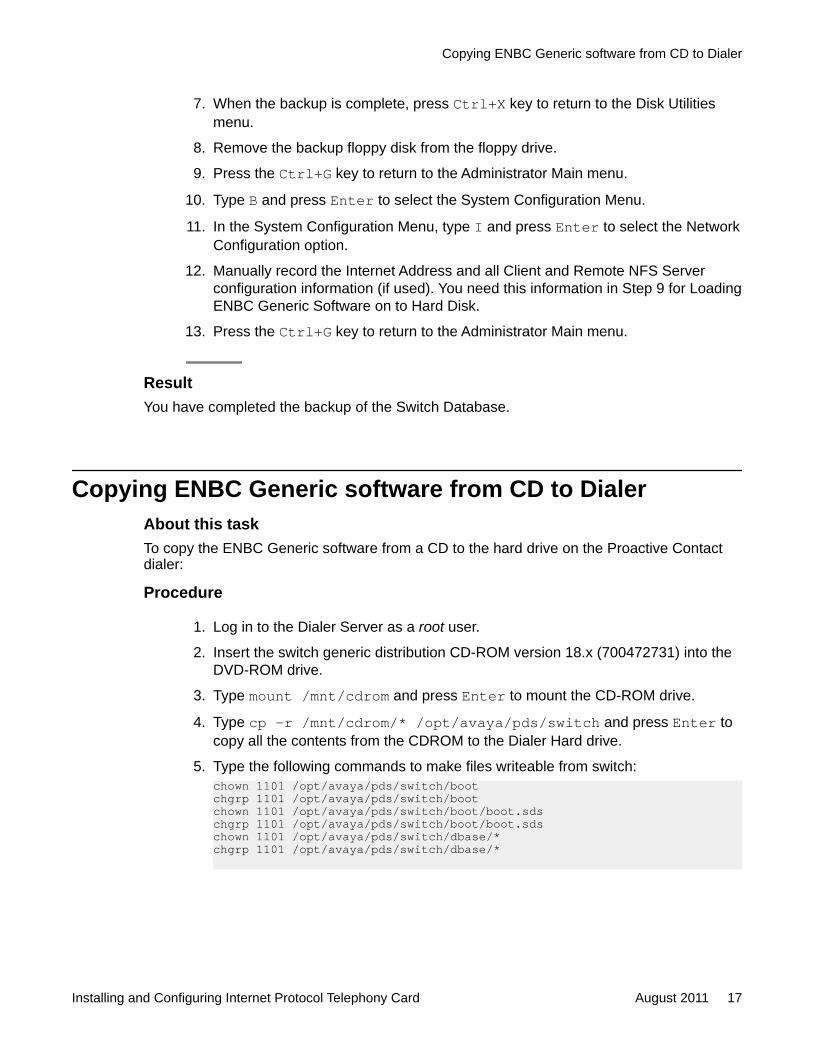
Copying ENBC Generic software from CD to DialerAbout this taskTo copy the ENBC Generic software from a CD to the hard drive on the Proactive Contactdialer:
Procedure
1. Log in to the Dialer Server as a root user.
2. Insert the switch generic distribution CD-ROM version 18.x (700472731) into theDVD-ROM drive.
3. Type mount /mnt/cdrom and press Enter to mount the CD-ROM drive.
4. Type cp –r /mnt/cdrom/* /opt/avaya/pds/switch and press Enter tocopy all the contents from the CDROM to the Dialer Hard drive.
5. Type the following commands to make files writeable from switch:chown 1101 /opt/avaya/pds/switch/bootchgrp 1101 /opt/avaya/pds/switch/bootchown 1101 /opt/avaya/pds/switch/boot/boot.sdschgrp 1101 /opt/avaya/pds/switch/boot/boot.sdschown 1101 /opt/avaya/pds/switch/dbase/*chgrp 1101 /opt/avaya/pds/switch/dbase/*
Copying ENBC Generic software from CD to Dialer
Installing and Configuring Internet Protocol Telephony Card August 2011 17

Note:User and group number was 101 before Proactive Contact version 5.0.
6. Type umount /mnt/cdrom and press Enter to unmount the CD-ROM.
7. Remove the CD.
8. Log out as a root user.
Shutting down the SwitchBefore you beginEnsure that no jobs are running on the Proactive Contact Dialer. Log in to the Dialer Server asan admin user and run the following commands to stop all the dialer processes:
Note:Incase of a Pod configuration, the mts and db processes are only present on the primarysystem.
• stop_pds• stop_mts• stop_db
After stopping all dialer processes, shut down the dialer. You must log in as a root user to shutdown the dialer.
About this taskTo shut down the Switch:
Procedure
1. At the Digital Switch Login screen, type the switch administrator user id andpassword for the switch and press Enter. The system displays the followingAdministrator Main Menu:A D M I N I S T R A T O R M A I N M E N U
Generic Version.Revision 18.0.7
A) Data Base Administration Menu
B) System Configuration Menu
C) Maintenance Menu
D) Diagnostics Menu
Upgrading to ENBC Generic v18.1
18 Installing and Configuring Internet Protocol Telephony Card August 2011Comments? [email protected]

Enter Selection: _
2. Type C and press Enter to select Maintenance Menu.
3. Type I and press Enter to select the Shut down System option.
4. Type H and press Enter to select Halt for System Shut down.
5. Press Enter again to confirm shut down of the switch.
Upgrading the ENBC software
Related topics:Turning on the Switch and running the Installation Utilities on page 19Loading the ENBC software on the hard drive on page 21Upgrading the ENBC Generic software on page 24Configuring the Ethernet / NFS Interface on page 25Installing ENBC ISDN/PRI option on page 27Restoring the Switch Database on page 28Terminating the Installation on page 29
Turning on the Switch and running the Installation UtilitiesIn this procedure we upgrade the ENBC Generic to 18.x.
Before you beginIf the upgrade is an incremental upgrade of a system running ENBC Generic 16.1 Rev-1(16.1.1), then you must delete the database files card.tbl, port.tbl, resgroup.tbl, and nfascnfg.tbland reboot the switch to create blank versions of these files. You must manually re-enter thecustomer database. You must perform this step to clean the database of a corruptionintroduced in 16.1 Rev 1. Create a file named clean161.txt and place the file in the c:/ directoryto mark the system as clean. Complete these actions to upgrade to 16.1 Rev 2 (16.1.2) orlater.
About this taskProcedure
1. Log in to the switch administrative console.
2. Type B and press Enter to go to the System Configuration Menu
3. Type I and press Enter to go to the Network Configuration screen.
Upgrading the ENBC software
Installing and Configuring Internet Protocol Telephony Card August 2011 19

Verify that the NFS drive status indicates that the NFS drive is mounted. If not, mountthe drive before proceeding.
4. Press Ctrl+G to return to the main menu.
5. To reboot the switch:
a. Type C and press Enter to select Maintenance Menu.
b. Type I and press Enter to select Shutdown System.
c. Press Enter.
d. Type R to reboot the switch.
If the version of generic is 17.0.1 or later, skip to step 8.
6. At the prompt, type 2 to select Enter Debug Monitor.
7. Type the following commands to change the boot drive from C: to F: type:mmb 808044<Enter>Modify: Enter new hex values, ‘.’ terminates command.00808044 – 43 >46<Enter>00808045 – 3A >.<Enter>
8. When you reboot the switch, the installation utilities run automatically.
• If the switch is turned on but currently in Debug Monitor mode, press Esc andpress Enter.
• If the previous generic software version is running, shutdown and reboot theENBC. Type C and press Enter. Type I and press Enter.
• If the version of ENBC Generic in use is 17.0.1 or later you will be given theoption to select I for install. Type I and press Enter to choose this option.
Note:If the floppy drive is not installed, set the NVRAM location 808104 to 0 to allowthe installed utilities or generic software to boot. Ensure that the ENBC EPROMSversion is 17.0.2 or later to be able to remove the floppy drive.
9. Reboot the switch. The switch displays the following:ENBC Main Boot Firmware v15.2 … ...
Reading boot file from disk device F:/boot/boot.sdsLoading file F:/boot/genkern.exeLoading file F:/boot/install.exe …
Boot File System is configured …Ethernet option is installed ...NFS option is installed ...ISDN/PRI option is installed ...NFAS option is installed ...
Installing disks ...***Error Mounting Floppy DiskSetting default device to F: ...Installing NFS driver …
Upgrading to ENBC Generic v18.1
20 Installing and Configuring Internet Protocol Telephony Card August 2011Comments? [email protected]
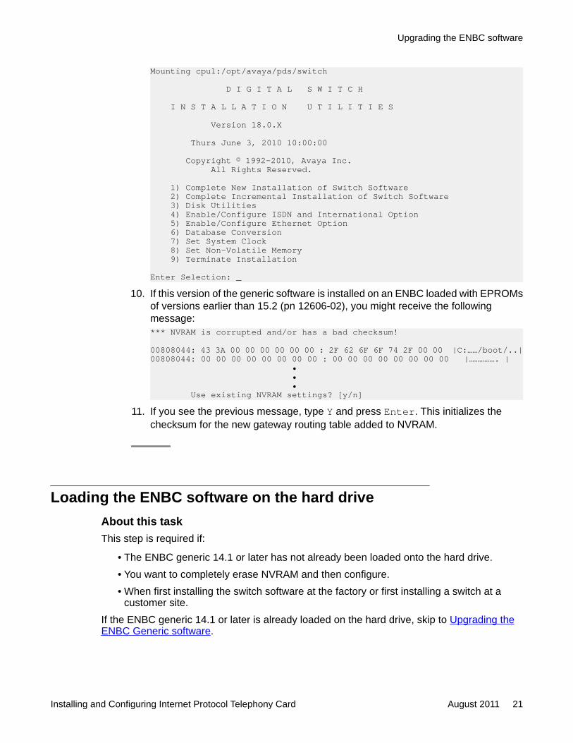
Mounting cpu1:/opt/avaya/pds/switch
D I G I T A L S W I T C H
I N S T A L L A T I O N U T I L I T I E S
Version 18.0.X
Thurs June 3, 2010 10:00:00
Copyright © 1992-2010, Avaya Inc. All Rights Reserved.
1) Complete New Installation of Switch Software 2) Complete Incremental Installation of Switch Software 3) Disk Utilities 4) Enable/Configure ISDN and International Option 5) Enable/Configure Ethernet Option 6) Database Conversion 7) Set System Clock 8) Set Non-Volatile Memory 9) Terminate Installation
Enter Selection: _10. If this version of the generic software is installed on an ENBC loaded with EPROMs
of versions earlier than 15.2 (pn 12606-02), you might receive the followingmessage:*** NVRAM is corrupted and/or has a bad checksum!
00808044: 43 3A 00 00 00 00 00 00 : 2F 62 6F 6F 74 2F 00 00 |C:……/boot/..|00808044: 00 00 00 00 00 00 00 00 : 00 00 00 00 00 00 00 00 |……………. | • • • Use existing NVRAM settings? [y/n]
11. If you see the previous message, type Y and press Enter. This initializes thechecksum for the new gateway routing table added to NVRAM.
Loading the ENBC software on the hard driveAbout this taskThis step is required if:
• The ENBC generic 14.1 or later has not already been loaded onto the hard drive.• You want to completely erase NVRAM and then configure.• When first installing the switch software at the factory or first installing a switch at a
customer site.If the ENBC generic 14.1 or later is already loaded on the hard drive, skip to Upgrading theENBC Generic software.
Upgrading the ENBC software
Installing and Configuring Internet Protocol Telephony Card August 2011 21

Procedure
1. At the Digital Switch Installation Utilities menu, type 1 and press Enter to selectthe Install/Configure Switch Generic Software option.The system displays the following message:System Clock = Thurs June 3, 2010 10:10:00
Do You Wish To Update The System Clock (Y/N) = [N]? 2. Type Y and press Enter.
The New date [12/08/2010]? option is displayed.
3. Type the new date in the mm/dd/yyyy format and press Enter.The New time [10:10:20]? option is displayed.
4. Type the new time in the hh:mm:ss format and press Enter.The switch displays the updated date and time.
5. In the Do You Wish to Back-Up The System Data Base? (Y/N) =message, type N and press Enter.
6. The following message is displayed:Device C: Will Be Reformatted. AllInformation Will Be Erased. Press Return to Continue. PressEnter to continue.
7. The following message is displayed.Formatting Device C: …
Erase NVRAM? (Y/N) = [N]?8. Type Y and press Enter.
Initializing Non-Volatile Memory …
System Internet Address = [xxx.xxx.xxx.xxx]? 9. Verify the displayed IP address is correct.
• If the IP address is not correct, enter the switch IP address for this site andpress Enter.
• If the IP address is correct, press Enter.
The following message is displayed.Enable NFS File Access (Y/N) = [Y]?
10. If you are mounting a directory remotely on the host system (for example, voice filesfor Mosaix 9.0 or later), type Y and press Enter to enable and configure the NFSoption as shown below. Otherwise, type N and press Enter to disable NFS.
a. In the Enable NFS File Access (Y/N) = [Y]? option, type Y and pressEnter.
b. In the Remote Server Internet Address = [xxx.xxx.xxx.xxx]?option, type the host IP address and press Enter.
Upgrading to ENBC Generic v18.1
22 Installing and Configuring Internet Protocol Telephony Card August 2011Comments? [email protected]

c. In the Remote Server Name = []? option, type the host name and pressEnter.
d. In the Remote Mount Directory = []? option, type the full path name ofthe host and press Enter.
e. In the Retries = [xx]? option, type 15 and press Enter.
f. In the Timeout = [x]? option, type 2 and press Enter.
g. In the Local Client Name = []? option, type the switch name and pressEnter.
h. In the User Id = [x]? option, type 1101 and press Enter.
i. In the Group Id = [x]? option, type 1101 and press Enter.
j. In the User Mask = [0]? option, type 002 and press Enter.
k. In the Update NFS Configuration With Above Data (Y/N) = [Y]?option, type Y and press Enter. The following message is displayed:NFS Configuration Updated
Ethernet Option Enabledl. In the Enable Gateway Routing Table (Y/N) = [N]? option, pressEnter. The following message is displayed:Gateway Routing Table Disabled
Createing subdirectory C://boot/colombia.optCopying F://boot/colombia.opt/ecpa.dwn to C://boot/colombia.opt/ecpa.dwn…Copying F://boot/colombia.opt/edtg.dwn to C://boot/colombia.opt/edtg.dwn…Copying F://boot/colombia.opt/ddc.dwn to C://boot/colombia.opt/ddc.dwn…etc. …
ISDN/PRI Option EnabledNFAS Option Enabled
Searching for country directories…
Installed countries (C:/BOOT/*.opt):
0 = [Default] 4 = FRANCE 8 = JAPAN 12 = S_AFRICA 1 = BRAZIL 5 = GLOBAL 9 = KOREA 13 = UK 2 = CHILE 6 = HONGKONG 10 = MALAYSIA 14 = US 3 = COLOMBIA 7 = INDIA 11 = MEXICO
The [Default] country uses the card download files loadedwith the switch generic software or loaded from an oldercountry-specific option disk.
Current Country = [0] [Default]m. In the Select New Country = [0]? option, type the number for the
appropriate country, and press Enter. The following message is displayed:New Country = [n] countryPCM Encodings (DDC, ECC, ECPA, EDRC, EDTG, EMFCR2 cards only):
Upgrading the ENBC software
Installing and Configuring Internet Protocol Telephony Card August 2011 23

0 = [Default] 1 = A-Law 2 = Mu-Law
Current PCM Encoding = [0] [Default]n. In the Select New PCM Encoding = [0]? option, press Enter.
Note:The PCM encoding is set to [Default]. Each card above will use the properencoding for the selected country. You may force these cards to a specificPCM encoding if necessary.
Next stepsSkip to Installing ENBC ISDN/PRI option.
Upgrading the ENBC Generic softwareThis topic describes how to upgrade from ENBC Generic 14.1.x or later to 18.x version. If youalready have ENBC Generic 18.x installed then skip to Installing ENBC ISDN/PRI option.
Before you beginYou must have ENBC Generic 14.1.x installed on the switch to upgrade to ENBC Generic18.x.
About this taskProcedure
1. In the Digital Switch Installation Utilities menu, type 2 and press Enter to selectthe Incremental Install of Switch Generic Software option. The system displays thesystem clock details.
2. In the Do You Wish To Update The System Clock (Y/N) = [N]? option,type N and press Enter.
3. In the Do You Wish to Back-Up The System Data Base? (Y/N) = option,type N and press Enter. The system displays the following message.All generic executables and card download files now reside in C:/boot/Delete old generic and download files in C:/ (Y/N) = [Y]?
4. Type Y and press Enter. The following message is displayed.Copying F://boot/colombia.opt/ecpa.dwn to C://boot/colombia.opt/ecpa.dwn…Copying F://boot/colombia.opt/edtg.dwn to C://boot/colombia.opt/edtg.dwn…Copying F://boot/colombia.opt/ddc.dwn to C://boot/colombia.opt/ddc.dwn…etc. …
Converting the database to run with Digital Switch release 18.0.x.The database will not be compatible with older releases.
Upgrading to ENBC Generic v18.1
24 Installing and Configuring Internet Protocol Telephony Card August 2011Comments? [email protected]

Continue with database conversion (Y/N) = [Y]? 5. If you want to restore the database before installation is complete, type N and press
Enter to skip this step. Otherwise type Y and press Enter to continue with thedatabase conversion.
6. In the Enter database directory path [C:/DBASE/]: option press Enterto continue. The system displays the following message.C:/dbase/dbvers.tbl...C:/dbase/syscnfg.tbl...C:/dbase/card.tbl...C:/dbase/port.tbl...C:/dbase/hostcnfg.tbl...C:/dbase/resgroup.tbl...C:/dbase/supvtmpl.tbl...C:/dbase/iprule.tbl...C:/dbase/oprule.tbl...C:/dbase/isdnsupv.tbl... C:/dbase/isdnmsg.tbl...C:/dbase/routesum.tbl...C:/dbase/routetbl.tbl...C:/dbase/exroute.tbl...C:/dbase/nfascnfg.tbl...
Press Return to Continue 7. Press Enter to continue.
Next stepsConfigure the Ethernet /NFS Interface.
Configuring the Ethernet / NFS InterfaceYou can re-enable or re-configure the Ethernet / NFS interface anytime (as necessary) withoutinstalling the ENBC Generic Software. If you do not want to change the Ethernet/NFS interfacethen skip to Installing ENBC ISDN/PRI option on page 27.
About this taskProcedure
1. In the Digital Switch Installation Utilities menu, type 5 and press Enter. Thefollowing options are displayed.E T H E R N E T C O N F I G U R A T I O N
1) Install Ethernet Option 2) Edit Ethernet Parameters 3) Edit NFS Parameters 4) Mount/Remount NFS Device 5) Dismount NFS Device 6) Exit Ethernet Configuration
Upgrading the ENBC software
Installing and Configuring Internet Protocol Telephony Card August 2011 25
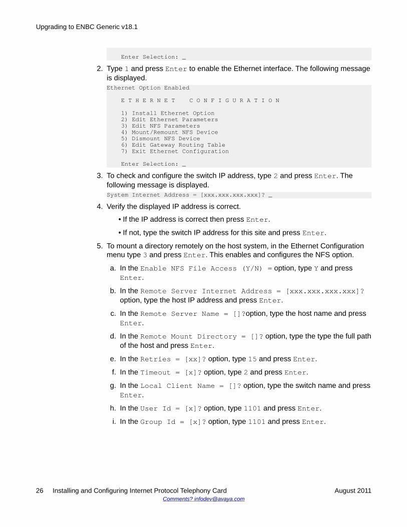
Enter Selection: _2. Type 1 and press Enter to enable the Ethernet interface. The following message
is displayed.Ethernet Option Enabled
E T H E R N E T C O N F I G U R A T I O N
1) Install Ethernet Option 2) Edit Ethernet Parameters 3) Edit NFS Parameters 4) Mount/Remount NFS Device 5) Dismount NFS Device 6) Edit Gateway Routing Table 7) Exit Ethernet Configuration
Enter Selection: _3. To check and configure the switch IP address, type 2 and press Enter. The
following message is displayed.System Internet Address = [xxx.xxx.xxx.xxx]? _
4. Verify the displayed IP address is correct.
• If the IP address is correct then press Enter.
• If not, type the switch IP address for this site and press Enter.
5. To mount a directory remotely on the host system, in the Ethernet Configurationmenu type 3 and press Enter. This enables and configures the NFS option.
a. In the Enable NFS File Access (Y/N) = option, type Y and pressEnter.
b. In the Remote Server Internet Address = [xxx.xxx.xxx.xxx]?option, type the host IP address and press Enter.
c. In the Remote Server Name = []?option, type the host name and pressEnter.
d. In the Remote Mount Directory = []? option, type the type the full pathof the host and press Enter.
e. In the Retries = [xx]? option, type 15 and press Enter.
f. In the Timeout = [x]? option, type 2 and press Enter.
g. In the Local Client Name = []? option, type the switch name and pressEnter.
h. In the User Id = [x]? option, type 1101 and press Enter.
i. In the Group Id = [x]? option, type 1101 and press Enter.
Upgrading to ENBC Generic v18.1
26 Installing and Configuring Internet Protocol Telephony Card August 2011Comments? [email protected]
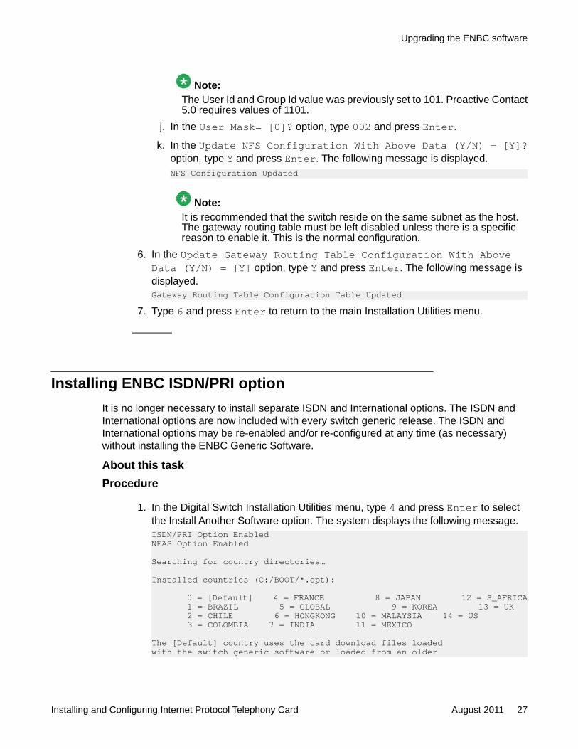
Note:The User Id and Group Id value was previously set to 101. Proactive Contact5.0 requires values of 1101.
j. In the User Mask= [0]? option, type 002 and press Enter.
k. In the Update NFS Configuration With Above Data (Y/N) = [Y]?option, type Y and press Enter. The following message is displayed.NFS Configuration Updated
Note:It is recommended that the switch reside on the same subnet as the host.The gateway routing table must be left disabled unless there is a specificreason to enable it. This is the normal configuration.
6. In the Update Gateway Routing Table Configuration With AboveData (Y/N) = [Y] option, type Y and press Enter. The following message isdisplayed.Gateway Routing Table Configuration Table Updated
7. Type 6 and press Enter to return to the main Installation Utilities menu.
Installing ENBC ISDN/PRI optionIt is no longer necessary to install separate ISDN and International options. The ISDN andInternational options are now included with every switch generic release. The ISDN andInternational options may be re-enabled and/or re-configured at any time (as necessary)without installing the ENBC Generic Software.
About this taskProcedure
1. In the Digital Switch Installation Utilities menu, type 4 and press Enter to selectthe Install Another Software option. The system displays the following message.ISDN/PRI Option EnabledNFAS Option Enabled
Searching for country directories…
Installed countries (C:/BOOT/*.opt):
0 = [Default] 4 = FRANCE 8 = JAPAN 12 = S_AFRICA 1 = BRAZIL 5 = GLOBAL 9 = KOREA 13 = UK 2 = CHILE 6 = HONGKONG 10 = MALAYSIA 14 = US 3 = COLOMBIA 7 = INDIA 11 = MEXICO
The [Default] country uses the card download files loadedwith the switch generic software or loaded from an older
Upgrading the ENBC software
Installing and Configuring Internet Protocol Telephony Card August 2011 27

country-specific option disk.
Current Country = [0] [Default]2. In the Select New Country = [0]? option, type the number for the appropriate
country, and press Enter. The following message is displayed:New Country = [n] countryPCM Encodings (DDC, ECC, ECPA, EDRC, EDTG, EMFCR2 cards only): 0 = [Default] 1 = A-Law 2 = Mu-Law
Current PCM Encoding = [0] [Default]3. In the Select New PCM Encoding = [0]? option, press Enter.
Note:The PCM encoding is set to [Default]. Each card above will use the properencoding for the selected country. You may force these cards to a specific PCMencoding if necessary.
Restoring the Switch DatabaseSwitch Database backup and restore can now be done on the server by coping files to andfrom the dbase directory. If you do not wish to restore an old database, skip to Terminating theInstallation on page 29
Procedure
1. In the Digital Switch Installation Utilities menu, type 3 and press Enter to selectthe Disk Utilities option.
2. Type 6 and press Enter to convert database. The following message isdisplayed.Converting database to run with Digital Switch release 18.0.x.The database will not be compatible with older releases.
3. In the Continue with database conversion (Y/N) = [Y]? option, pressEnter.
4. In the Enter database directory path [C:/DBASE/]: option, pressEnter. The following message is displayed.C:/dbase/dbvers.tbl...C:/dbase/syscnfg.tbl...C:/dbase/card.tbl...C:/dbase/port.tbl...C:/dbase/hostcnfg.tbl...C:/dbase/resgroup.tbl...C:/dbase/supvtmpl.tbl...C:/dbase/iprule.tbl...C:/dbase/oprule.tbl...
Upgrading to ENBC Generic v18.1
28 Installing and Configuring Internet Protocol Telephony Card August 2011Comments? [email protected]
C:/dbase/isdnsupv.tbl...C:/dbase/routesum.tbl...C:/dbase/routetbl.tbl...C:/dbase/exroute.tbl...C:/dbase/nfascnfg.tbl...
Press Return to Continue 5. Press Enter to complete the process.
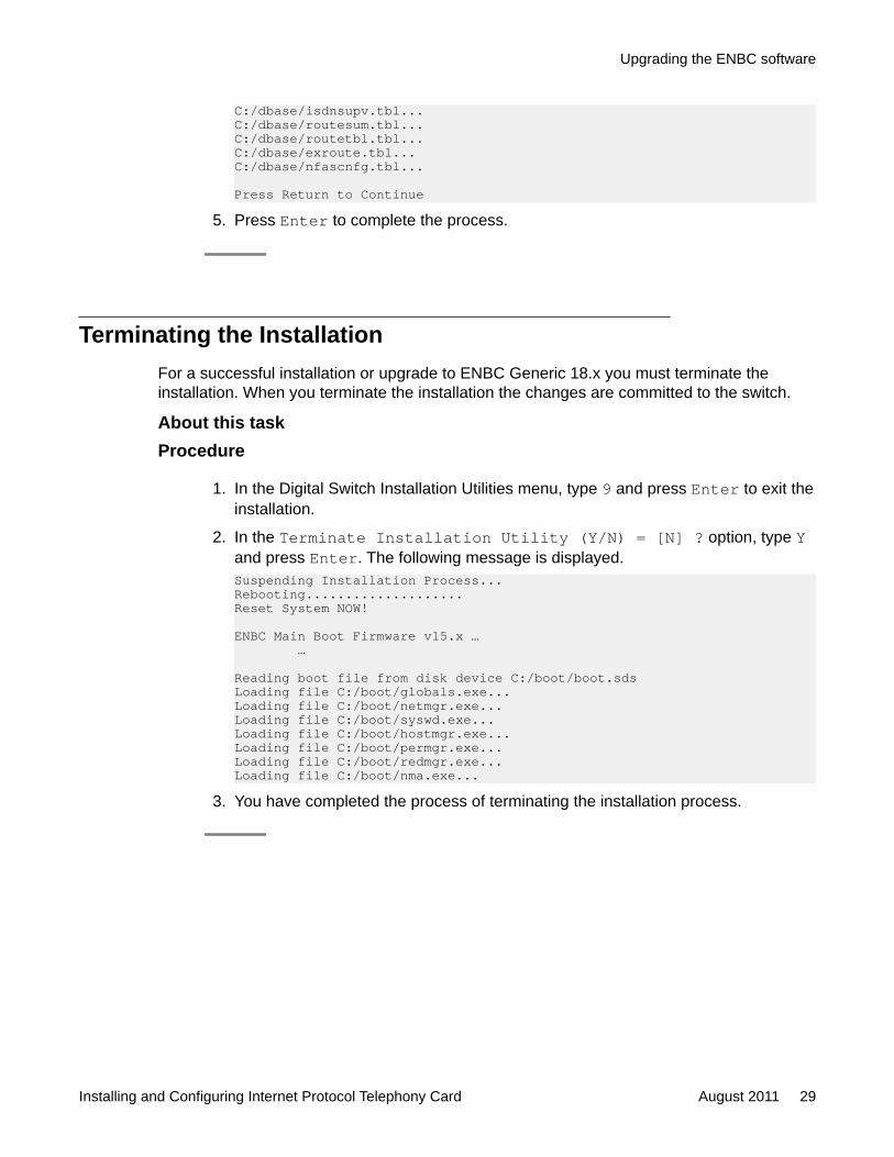
Terminating the InstallationFor a successful installation or upgrade to ENBC Generic 18.x you must terminate theinstallation. When you terminate the installation the changes are committed to the switch.
About this taskProcedure
1. In the Digital Switch Installation Utilities menu, type 9 and press Enter to exit theinstallation.
2. In the Terminate Installation Utility (Y/N) = [N] ? option, type Yand press Enter. The following message is displayed.Suspending Installation Process...Rebooting....................Reset System NOW!
ENBC Main Boot Firmware v15.x … …
Reading boot file from disk device C:/boot/boot.sdsLoading file C:/boot/globals.exe...Loading file C:/boot/netmgr.exe...Loading file C:/boot/syswd.exe...Loading file C:/boot/hostmgr.exe...Loading file C:/boot/permgr.exe...Loading file C:/boot/redmgr.exe...Loading file C:/boot/nma.exe...
3. You have completed the process of terminating the installation process.
Upgrading the ENBC software
Installing and Configuring Internet Protocol Telephony Card August 2011 29

Upgrading to ENBC Generic v18.1
30 Installing and Configuring Internet Protocol Telephony Card August 2011Comments? [email protected]

Chapter 4: Configuring IPTC (on PG230RM,PG230, 5 foot cabinets, or anysystem that has been upgradedto the ENBC)
Configuring the IPTCTo configure the card you must first add the card in the PG230RM switch.
About this taskBefore you use a card, you must add the card in the PG230RM switch software. The card canbe in three states:
• Activated: To start using the card, you must change the state of the card to active.• Out Of Service: When you add a card it is by default in Out Of Service state. For modifying
any card parameters, you must change the state of the card to Out Of Service. To deletea card, you must first change the state of the card to Out of Service.
• Maintenance: When you are carrying out maintenance work on the card, you must changethe state of the card to Maintenance.
Procedure
1. Adding a card in the PG230RM on page 32
2. Activating the card on page 33
3. Changing the state of the card to Out Of Service on page 34
4. Deleting a card from the PG230RM on page 35
Related topics:Adding a card in the PG230RM on page 32Activating the card on page 33Changing the state of the card to Out Of Service on page 34Deleting a card from the PG230RM on page 35
Installing and Configuring Internet Protocol Telephony Card August 2011 31
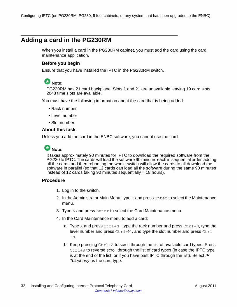
Adding a card in the PG230RMWhen you install a card in the PG230RM cabinet, you must add the card using the cardmaintenance application.
Before you beginEnsure that you have installed the IPTC in the PG230RM switch.
Note:PG230RM has 21 card backplane. Slots 1 and 21 are unavailable leaving 19 card slots.2048 time slots are available.
You must have the following information about the card that is being added:
• Rack number• Level number• Slot number
About this taskUnless you add the card in the ENBC software, you cannot use the card.
Note:It takes approximately 90 minutes for IPTC to download the required software from thePG230 to IPTC. The cards will load the software 90 minutes each in sequential order, addingall the cards and then rebooting the whole switch will allow the cards to all download thesoftware in parallel (so that 12 cards can load all the software during the same 90 minutesinstead of 12 cards taking 90 minutes sequentially = 18 hours).
Procedure
1. Log in to the switch.
2. In the Administrator Main Menu, type C and press Enter to select the Maintenancemenu.
3. Type A and press Enter to select the Card Maintenance menu.
4. In the Card Maintenance menu to add a card:
a. Type A and press Ctrl+N , type the rack number and press Ctrl+N, type thelevel number and press Ctrl+N , and type the slot number and press Ctrl+N.
b. Keep pressing Ctrl+A to scroll through the list of available card types. PressCtrl+R to reverse scroll through the list of card types (in case the IPTC typeis at the end of the list, or if you have past IPTC through the list). Select IPTelephony as the card type.
Configuring IPTC (on PG230RM, PG230, 5 foot cabinets, or any system that has been upgraded to the ENBC)
32 Installing and Configuring Internet Protocol Telephony Card August 2011Comments? [email protected]

c. Press Enter to select the card type.
ExampleTo add a IPTC located at rack 1, level 1, and slot 17, type A Ctrl+N 1 Crtl+N 1 Ctrl+N17 Ctrl+N. When you do this step, the system displays data in a form very similar to thefollowing.C A R D M A I N T E N A N C E
R L S CARD TYPE V.RV S R L S CARD TYPE V.RV S-------- ---------------------- ----- - - - ---- ---------------------- ----- -1 1 1 Enhanced Network Bus 15.02 A 1 1 20-2 4-Span Quad E1 PRI-120 O1 1 3-1 Tone Generator DSP2-41 1.02 A 1 1 20-3 4-Span Quad E1 PRI-120 O1 1 3-2 Call Progress DSP2-41 1.02 A 1 1 20-4 4-Span Quad E1 PRI-120 O1 1 3-3 Conference DSP2-41 1.02 A1 1 3-4 DTMF Receiver DSP2-41 1.02 A1 1 4 Large Port Voice Card2 10.01 A1 1 16 IP Telephony 1.07 A1 1 18 IP Telephony O1 1 19 IP Telephony O1 1 20-1 4-Span Quad E1 PRI-120 O
A)DD, D)ELETE, C)HANGE, P)ORT: A 1 1 17__ IP Telephony PORTS: 128 O 1- 64: 11111111 11111111 11111111 11111111 11111111 11111111 11111111 11111111 65-128: 11111111 11111111 11111111 11111111 11111111 11111111 11111111 11111111129-192:193-248:
Activating the cardAfter adding a card to the Switch software, you must activate the card. By default, the card isin a Out of Service state.
Before you beginYou must add the card to the software before activating the card.
About this taskUsing the following steps, you can activate one or more cards.
Procedure
1. Log in to the switch.
2. In the Administrator Main Menu, type C and press Enter to select the Maintenancemenu.
3. Type A and press Enter to select the Card Maintenance menu.
4. In the Card Maintenance menu to activate a card:
Configuring the IPTC
Installing and Configuring Internet Protocol Telephony Card August 2011 33

Type C and press Ctrl+N, type the rack number and press Ctrl+N, type the levelnumber and press Ctrl+N, and type the slot number followed with a hyphen andthe span number and press Enter. Type A and press Enter.
For example, to activate a IP Telephony card located at rack 1, level 1, and slot 13,type C Ctrl+N 1 Crtl+N 1 Ctrl+N 13 and press Enter. Type A and pressEnter to activate the card. When you perform this step, the system displays datasimilar to the following example.C A R D M A I N T E N A N C E
R L S CARD TYPE V.RV S R L S CARD TYPE V.RV S-------- ---------------------- ----- - - - ---- ---------------------- ----- -1 1 1 Enhanced Network Bus 15.02 A 1 1 11 Enhanced DTMF Receiver 1.06 A1 1 2 Enhanced DTG 1.00 A 1 1 12 Digital Dialer Card 1.00 A1 1 3 Large Port Voice Card 2.03 A 1 1 13 IP Telephony Card O1 1 4 Large Port Voice Card 2.03 A 1 1 13-1 4-Span Quad T1 PRI A1 1 5 Conference Card 10.01 A 1 1 13-2 4-Span Quad T1 PRI O1 1 6 Enhanced Call Progress 1.00 A 1 1 13-3 4-Span Quad T1 PRI O1 1 7 Enhanced Call Progress 1.00 A 1 1 14-1 96-Port Quad T1 1.00 M1 1 8 Enhanced Call Progress 1.00 A 1 1 14-2 96-Port Quad T1 1.00 M1 1 9 Enhanced Call Progress 1.00 A 1 1 14-3 96-Port Quad T1 1.00 M1 1 10 Enhanced Call Progress 1.00 A 1 1 14-4 96-Port Quad T1 1.00 M
A)DD, D)ELETE, C)HANGE, P)ORT: C 1 1 13 IP Telephony Card PORTS: 128 A 1- 64: 11111111 11111111 11111110 65-128:129-192:193-248:
Changing the state of the card to Out Of ServiceAbout this taskYou must set the state of the card to Out Of Service:
• When you change the parameter of the card.• When you delete a card. You must remove the card span from any resource group and
change the card state to Out Of Service.
Configuring IPTC (on PG230RM, PG230, 5 foot cabinets, or any system that has been upgraded to the ENBC)
34 Installing and Configuring Internet Protocol Telephony Card August 2011Comments? [email protected]
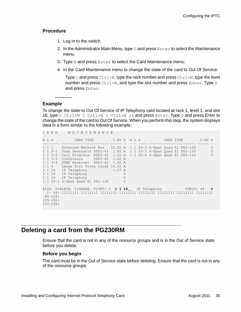
Procedure
1. Log in to the switch.
2. In the Administrator Main Menu, type C and press Enter to select the Maintenancemenu.
3. Type A and press Enter to select the Card Maintenance menu.
4. In the Card Maintenance menu to change the state of the card to Out Of Service:
Type C and press Ctrl+N, type the rack number and press Ctrl+N, type the levelnumber and press Ctrl+N, and type the slot number and press Enter. Type Oand press Enter.
ExampleTo change the state to Out Of Service of IP Telephony card located at rack 1, level 1, and slot16, type C Ctrl+N 1 Crtl+N 1 Ctrl+N 16 and press Enter. Type O and press Enter tochange the state of the card to Out Of Service. When you perform this step, the system displaysdata in a form similar to the following example:C A R D M A I N T E N A N C E
R L S CARD TYPE V.RV S R L S CARD TYPE V.RV S-------- ---------------------- ----- - - - ---- ---------------------- ----- -1 1 1 Enhanced Network Bus 15.02 A 1 1 20-2 4-Span Quad E1 PRI-120 O1 1 3-1 Tone Generator DSP2-41 1.02 A 1 1 20-3 4-Span Quad E1 PRI-120 O1 1 3-2 Call Progress DSP2-41 1.02 A 1 1 20-4 4-Span Quad E1 PRI-120 O1 1 3-3 Conference DSP2-41 1.02 A1 1 3-4 DTMF Receiver DSP2-41 1.02 A1 1 4 Large Port Voice Card2 10.01 A1 1 16 IP Telephony 1.07 A1 1 18 IP Telephony O1 1 19 IP Telephony O1 1 20-1 4-Span Quad E1 PRI-120 O
A)DD, D)ELETE, C)HANGE, P)ORT: C 1 1 16__ IP Telephony PORTS: 64 O 1- 64: 11111111 11111111 11111111 11111111 11111111 11111111 11111111 11111111 65-128:129-192:193-248:
Deleting a card from the PG230RMEnsure that the card is not in any of the resource groups and is in the Out of Service statebefore you delete.
Before you beginThe card must be in the Out of Service state before deleting. Ensure that the card is not in anyof the resource groups.
Configuring the IPTC
Installing and Configuring Internet Protocol Telephony Card August 2011 35
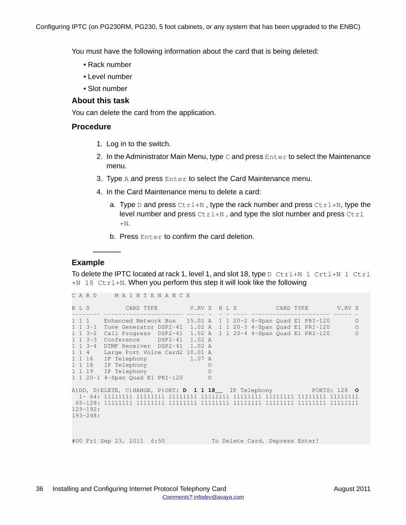
You must have the following information about the card that is being deleted:
• Rack number• Level number• Slot number
About this taskYou can delete the card from the application.
Procedure
1. Log in to the switch.
2. In the Administrator Main Menu, type C and press Enter to select the Maintenancemenu.
3. Type A and press Enter to select the Card Maintenance menu.
4. In the Card Maintenance menu to delete a card:
a. Type D and press Ctrl+N , type the rack number and press Ctrl+N, type thelevel number and press Ctrl+N , and type the slot number and press Ctrl+N.
b. Press Enter to confirm the card deletion.
ExampleTo delete the IPTC located at rack 1, level 1, and slot 18, type D Ctrl+N 1 Crtl+N 1 Ctrl+N 18 Ctrl+N. When you perform this step it will look like the following
C A R D M A I N T E N A N C E
R L S CARD TYPE V.RV S R L S CARD TYPE V.RV S-------- ---------------------- ----- - - - ---- ---------------------- ----- -1 1 1 Enhanced Network Bus 15.02 A 1 1 20-2 4-Span Quad E1 PRI-120 O1 1 3-1 Tone Generator DSP2-41 1.02 A 1 1 20-3 4-Span Quad E1 PRI-120 O1 1 3-2 Call Progress DSP2-41 1.02 A 1 1 20-4 4-Span Quad E1 PRI-120 O1 1 3-3 Conference DSP2-41 1.02 A1 1 3-4 DTMF Receiver DSP2-41 1.02 A1 1 4 Large Port Voice Card2 10.01 A1 1 16 IP Telephony 1.07 A1 1 18 IP Telephony O1 1 19 IP Telephony O1 1 20-1 4-Span Quad E1 PRI-120 O
A)DD, D)ELETE, C)HANGE, P)ORT: D 1 1 18__ IP Telephony PORTS: 128 O 1- 64: 11111111 11111111 11111111 11111111 11111111 11111111 11111111 11111111 65-128: 11111111 11111111 11111111 11111111 11111111 11111111 11111111 11111111129-192:193-248:
#00 Fri Sep 23, 2011 6:50 To Delete Card, Depress Enter!
Configuring IPTC (on PG230RM, PG230, 5 foot cabinets, or any system that has been upgraded to the ENBC)
36 Installing and Configuring Internet Protocol Telephony Card August 2011Comments? [email protected]
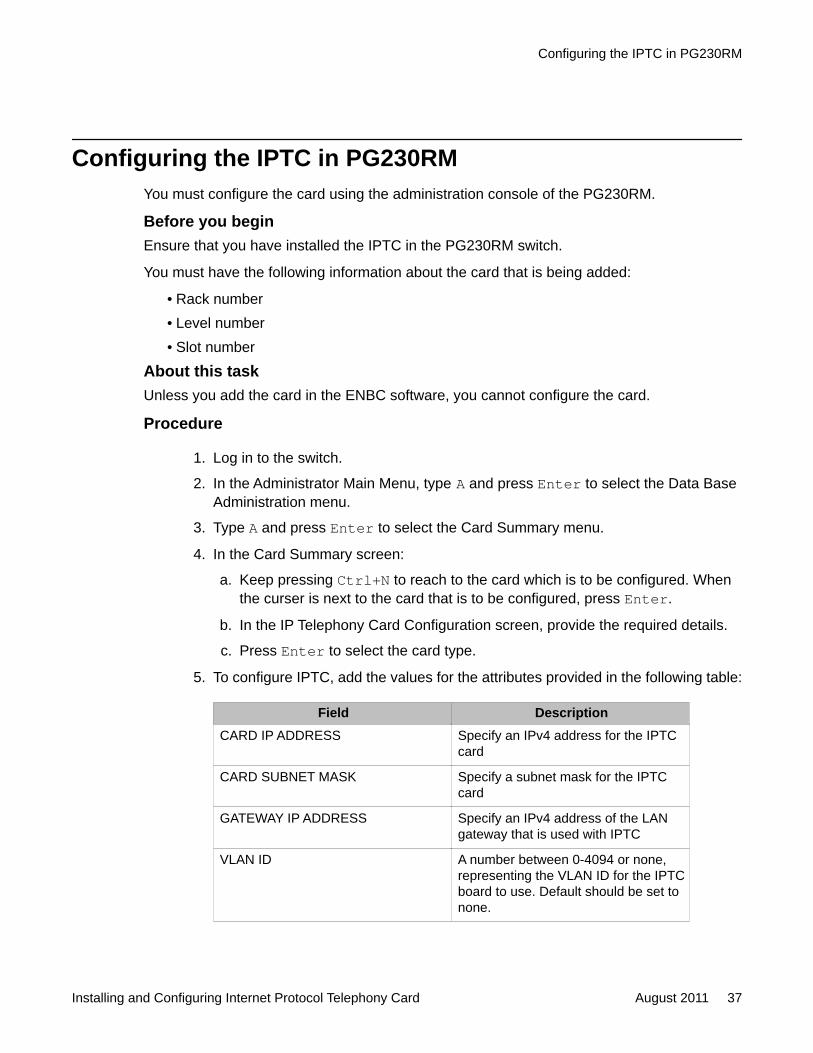
Configuring the IPTC in PG230RMYou must configure the card using the administration console of the PG230RM.
Before you beginEnsure that you have installed the IPTC in the PG230RM switch.
You must have the following information about the card that is being added:
• Rack number• Level number• Slot number
About this taskUnless you add the card in the ENBC software, you cannot configure the card.
Procedure
1. Log in to the switch.
2. In the Administrator Main Menu, type A and press Enter to select the Data BaseAdministration menu.
3. Type A and press Enter to select the Card Summary menu.
4. In the Card Summary screen:
a. Keep pressing Ctrl+N to reach to the card which is to be configured. Whenthe curser is next to the card that is to be configured, press Enter.
b. In the IP Telephony Card Configuration screen, provide the required details.
c. Press Enter to select the card type.
5. To configure IPTC, add the values for the attributes provided in the following table:
Field DescriptionCARD IP ADDRESS Specify an IPv4 address for the IPTC
card
CARD SUBNET MASK Specify a subnet mask for the IPTCcard
GATEWAY IP ADDRESS Specify an IPv4 address of the LANgateway that is used with IPTC
VLAN ID A number between 0-4094 or none,representing the VLAN ID for the IPTCboard to use. Default should be set tonone.
Configuring the IPTC in PG230RM
Installing and Configuring Internet Protocol Telephony Card August 2011 37

Field DescriptionSPEED Default value is Auto-negotiate
MONITOR IP ADDRESS
RTCP MONITORING
MONITOR PORT Default value is 5005
RTCP REPORT PERIOD Default value is 5
DIFFSERV CALL CONTROL Default value is 34
802.1P/Q CALL CONTROL Default value is 7
DIFFSERV AUDIO Default value is 46
802.1P/Q AUDIO Default value is 0
ExampleWhen you perform the above steps, the system displays data in a form very similar to thefollowing.I P T E L E P H O N Y C A R D C O N F I G U R A T I O N CARD LOCATION: R,L,S 1 1 17 TYPE: IP Telephony STATUS: Out of ServiceCARD IP ADDRESS: _______________ VLAN ID: NoneCARD SUBNET MASK: _______________ SPEED: Auto-negotiateGATEWAY IP ADDRESS: _______________ MONITOR IP ADDRESS: _______________RTCP MONITORING: Off MONITOR PORT: 5005 RTCP REPORT PERIOD: 5DIFFSERV CALL CONTROL: 34 802.1P/Q CALL CONTROL: 7DIFFSERV AUDIO: 46 802.1P/Q AUDIO: 0AUDIO GAIN (IP->TDM/TDM->IP): Country Default PORT NAME GROUP GRP NAME IP RULE COS SIG GRP ------ -------- ----- -------- ------- ----- ------- 41 __ ________ 0 0 42 __ ________ 0 0 43 __ ________ 0 0 44 __ ________ 0 0 45 __ ________ 0 0 46 __ ________ 0 0 47 __ ________ 0 0 48 __ ________ 0 0
Configuring the IP Signaling groupYou must configure the IP Signaling group using the administration console of thePG230RM.
Before you beginEnsure that you have installed the IPTC in the PG230RM switch.
Configuring IPTC (on PG230RM, PG230, 5 foot cabinets, or any system that has been upgraded to the ENBC)
38 Installing and Configuring Internet Protocol Telephony Card August 2011Comments? [email protected]
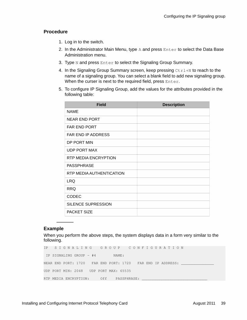
Procedure
1. Log in to the switch.
2. In the Administrator Main Menu, type A and press Enter to select the Data BaseAdministration menu.
3. Type N and press Enter to select the Signaling Group Summary.
4. In the Signaling Group Summary screen, keep pressing Ctrl+N to reach to thename of a signaling group. You can select a blank field to add new signaling group.When the curser is next to the required field, press Enter.
5. To configure IP Signaling Group, add the values for the attributes provided in thefollowing table:
Field DescriptionNAME
NEAR END PORT
FAR END PORT
FAR END IP ADDRESS
DP PORT MIN
UDP PORT MAX
RTP MEDIA ENCRYPTION
PASSPHRASE
RTP MEDIA AUTHENTICATION
LRQ
RRQ
CODEC
SILENCE SUPRESSION
PACKET SIZE
ExampleWhen you perform the above steps, the system displays data in a form very similar to thefollowing.IP S I G N A L I N G G R O U P C O N F I G U R A T I O N
IP SIGNALING GROUP - #4 NAME:
NEAR END PORT: 1720 FAR END PORT: 1720 FAR END IP ADDRESS: _______________
UDP PORT MIN: 2048 UDP PORT MAX: 65535
RTP MEDIA ENCRYPTION: Off PASSPHRASE: ______________________________
Configuring the IP Signaling group
Installing and Configuring Internet Protocol Telephony Card August 2011 39

RTP MEDIA AUTHENTICATION: Off LRQ: N RRQ: N
ORDER CODEC SILENCE SUPRESSION PACKET SIZE ----- ----------- ------------------ ----------- 1 __________ Off ____ 2 __________ Off ____ 3 __________ Off ____ 4 __________ Off ____ 5 __________ Off ____ 6 __________ Off ____ 7 __________ Off ____
Diagnostic for IPTCThree new menu options are added in the Diagnostic menu for IPTC. To access the menu,login to the switch and select Diagnostics menu to access the submenus.
• IPTC Statistics• IPTC Call Statistics• IPTC Diagnostics
IPTC StatisticsProvides statistics related to all activity on the card. For IPTC statistics type the rack number,level number, and slot number of the IPTC to monitor and press Enter.I P T C S T A T I S T I C S D I S P L A Y
R,L,S 1 1 16__ Type: IPTC FW 1.07 Serial Number: 1751134202Status: Active MAC: 00.1B.4F.54.45.44 Last Reset: 09/22/2011 23:51:42IP Address: 148.147.173.153 Netmask: 255.255.255.0 Gateway: 148.147.173.1DSP #1 Cores: 4 DSP #2 Cores: 4
Hourly Statistics time frame start: 23:24:13 stop: 00:24:13
Octets Datagrams Discards Header Errors ---------- ---------- ---------- -------------Received since last reset: __________ __________ __________ __________Received since last hour: __________ __________ __________ __________Transmitted since last reset: __________ __________ __________ __________Transmitted since last hour: __________ __________ __________ __________
Redirects Dest. Unreachable ---------- ------------------Received ICMP since last reset: __________ __________Received ICMP since last hour: __________ __________
CP: STATS
IPTC Call StatisticsProvides statistics related to all activity on the card. For call statistics, type the IPTC portaddress and press Enter.I P T C C A L L S T A T I S T I C S D I S P L A Y
Configuring IPTC (on PG230RM, PG230, 5 foot cabinets, or any system that has been upgraded to the ENBC)
40 Installing and Configuring Internet Protocol Telephony Card August 2011Comments? [email protected]

RLSP: 1 1 16 1 PA: 1B8 TYPE: IPTCCURRENT STATE IP Address Port UDP Port Sig GrpMajor CP_IDLE Near End 148.147.173.153 _____ _____ ___Supplementary 0 Far End _______________ _____
RTP OPTIONS USED THIS CALL Codec Type ___________ Packet Size ____ Silence Suppression ___ Encryption ___ Authentication ______
JITTER AVERAGE FOR ONE SECOND INTERVALS (ms) Current Buffer Size _____Last ____ ____ ____ ____ ____ ____ ____ ____ ____ ____ Worst ____ Average ____
PACKET LOSS FOR ONE SECOND INTERVALSLast ____ ____ ____ ____ ____ ____ ____ ____ ____ ____ Worst ____ Average ____
CALL STATISTICSOut of Order ____ SSRC Change ____ Last Rx Seq. # _____ Last Tx Seq. # _____Echo Return Loss _____ Bulk Delay _____ Echo Return Loss Enhancement _____
CP: PORT STATS
IPTC DiagnosticsProvides tools for testing IPTC and it's connections. For IPTC diagnostics, type the racknumber, level number, and slot number of the IPTC and far end IP address if required bydiagnostic to be executed. Select the required diagnostic to run and change the value from “N”to “Y” and press Enter. The results are displayed.I P T C D I A G N O S T I C SRLS: 1 1 16 Card IP Address: 148.147.173.153Far End Address:
Enable CLI interface? N Reset DSP? (1,2,N) N
Execute Ethernet Loopback Test? N Result:
Execute Ping Test? N Result Time Description
Execute Trace Route Test? N (Results are saved in switch log file) Hop Time(ms) IP Address ___ _____ _____ _____ ________________ ___ _____ _____ _____ ________________ ___ _____ _____ _____ ________________ ___ _____ _____ _____ ________________ ___ _____ _____ _____ ________________
Diagnostic for IPTC
Installing and Configuring Internet Protocol Telephony Card August 2011 41

Configuring IPTC (on PG230RM, PG230, 5 foot cabinets, or any system that has been upgraded to the ENBC)
42 Installing and Configuring Internet Protocol Telephony Card August 2011Comments? [email protected]

Chapter 5: Configuring CommunicationManager for IPTC
Using IPTC with Communication ManagerThe dialer switch currently communicates to the CM with E1 or T1 lines which may or may nothave ISDN on them. The IPTC now provided a VoIP method to connect to the CM for agentlines. transfer trunks, inbound and outbound lines.
This chapter only lists the fields and configuration settings that are required for IPTC. For moredetails on additional configuration on CM refer to Avaya Aura® Communication ManagerScreen Reference guide.
Adding the IP codec setIP Codec set specifies the type of codec used for voice encoding and companding(compression/ decompression).
The default codec is set for G711MU. The G711MU provides the highest voice quality, but ituses the most bandwidth. The G711MU default setting can be changed to one of two othercodecs if the G711MU does not meet your desired voice-quality/bandwidth trade-offspecification. For more details on the IP codec set screen see IP codec set in the Avaya Aura®
Communication Manager Screen Reference guide.
You must add the IP codec set in Communication Manager to establish successful RTP pathwith the customer.
Procedure
1. On the SAT session, in the Command: prompt, type change ip-codec-set nand press Enter. The n is the ip codec set number. The IP Codec Set screenappears.
2. Use the up or down arrow key to scroll. In the first page, provide the followinginformation:
• Audio Codec
Installing and Configuring Internet Protocol Telephony Card August 2011 43

• Silence Suppression
• Frames Per Packet
• Packet Size in milliseconds
3. The first screen of IP Codec Set displays the information similar to the one providedbelow.change ip-codec-set 1 Page 1 of 2
IP Codec Set
Codec Set: 1
Audio Silence Frames Packet Codec Suppression Per Pkt Size(ms) 1: G.711MU n 2 20 2: 3: 4: 5: 6: 7:
Media Encryption 1: none 2: 3:
Note:Take a note of Codec Set number. This is required for configuring IP NetworkRegion.
4. Press the F3 key to save the changes.
Adding the IP network regionYou must define the Authoritative Domain name on the IP-network-region form.
The IP Network Region configures within-region and between-region connectivity settings forall VoIP resources and endpoints within a given IP region. The first page is used to modify theaudio and QoS settings. The Codec Set field on this page reflects the CODEC set that mustbe used for connections between telephones within this region or between telephones andMedPro/Prowler boards and gateways within this region. The ability to do NAT shuffling fordirect IP-to-IP audio connections is also supported.
For more details on the IP network region screen see IP network region in the Avaya Aura®
Communication Manager Screen Reference guide.
Configuring Communication Manager for IPTC
44 Installing and Configuring Internet Protocol Telephony Card August 2011Comments? [email protected]
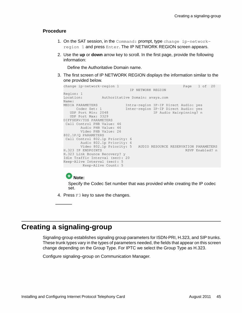
Procedure
1. On the SAT session, in the Command: prompt, type change ip-network-region 1 and press Enter. The IP NETWORK REGION screen appears.
2. Use the up or down arrow key to scroll. In the first page, provide the followinginformation:
Define the Authoritative Domain name.
3. The first screen of IP NETWORK REGION displays the information similar to theone provided below.change ip-network-region 1 Page 1 of 20 IP NETWORK REGIONRegion: 1Location: Authoritative Domain: avaya.comName:MEDIA PARAMETERS Intra-region IP-IP Direct Audio: yes Codec Set: 1 Inter-region IP-IP Direct Audio: yes UDP Port Min: 2048 IP Audio Hairpinning? n UDP Port Max: 3329DIFFSERV/TOS PARAMETERS Call Control PHB Value: 46 Audio PHB Value: 46 Video PHB Value: 26802.1P/Q PARAMETERS Call Control 802.1p Priority: 6 Audio 802.1p Priority: 6 Video 802.1p Priority: 5 AUDIO RESOURCE RESERVATION PARAMETERSH.323 IP ENDPOINTS RSVP Enabled? nH.323 Link Bounce Recovery? yIdle Traffic Interval (sec): 20Keep-Alive Interval (sec): 5 Keep-Alive Count: 5
Note:Specify the Codec Set number that was provided while creating the IP codecset.
4. Press F3 key to save the changes.
Creating a signaling-groupSignaling-group establishes signaling group parameters for ISDN-PRI, H.323, and SIP trunks.These trunk types vary in the types of parameters needed, the fields that appear on this screenchange depending on the Group Type. For IPTC we select the Group Type as H.323.
Configure signaling–group on Communication Manager.
Creating a signaling-group
Installing and Configuring Internet Protocol Telephony Card August 2011 45

Procedure
1. On the SAT session, in the Command: terminal, type add signaling-group nand press Enter.The system displays the SIGNALING GROUP screen.
The n is the signaling-group number.
2. Use the up or down arrow key and scroll to the Group Type option.
3. In the Group Type option, type SIP and press tab key.The SIGNALING GROUP screen displays the information as provided below:add signaling-group 14 Page 1 of 5 SIGNALING GROUP
Group Number: 14 Group Type: h.323 Remote Office? n Max number of NCA TSC: 5 SBS? n Max number of CA TSC: 0 IP Video? n Trunk Group for NCA TSC: 14 Trunk Group for Channel Selection: 14 X-Mobility/Wireless Type: NONE TSC Supplementary Service Protocol: a Network Call Transfer? y T303 Timer(sec): 10 Location Routing Inc Calls: H.245 DTMF Signal Tone Duration(msec): Near-end Node Name: newclan123 Far-end Node Name: iptc-1 Near-end Listen Port: 5999 Far-end Listen Port: 5005 Far-end Network Region: 1 LRQ Required? n Calls Share IP Signaling Connection? n RRQ Required? n Media Encryption? n Bypass If IP Threshold Exceeded? n H.235 Annex H Required? n DTMF over IP: rtp-payload Direct IP-IP Audio Connections? y Link Loss Delay Timer(sec): 90 IP Audio Hairpinning? n Enable Layer 3 Test? n Interworking Message: PROGressH.323 Station Outgoing Direct Media? n DCP/Analog Bearer Capability: 3.1kHz
F1=Cancel F2=Refresh F3=Submit F4=Clr Fld F5=Help F6=Update F7=Nxt Pg F8=Prv Pg
4. Update the following values:
Field Default Value DescriptionGroup Type h.323 The type of protocol used
with the signaling group.
Trunk Group for ChannelSelection
Trunk group number ofthe H.323 trunk
Near-end Node Name For G650, provide theCLAN nameFor G450, provide theprocr name
Configuring Communication Manager for IPTC
46 Installing and Configuring Internet Protocol Telephony Card August 2011Comments? [email protected]
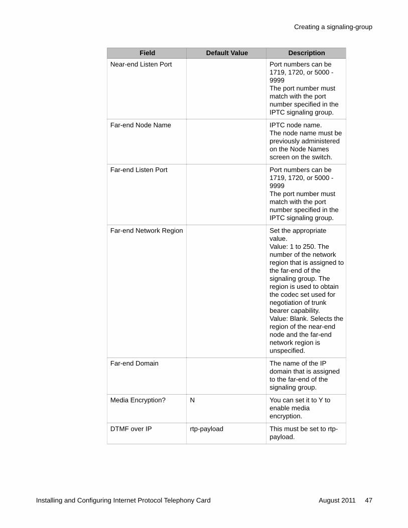
Field Default Value DescriptionNear-end Listen Port Port numbers can be
1719, 1720, or 5000 -9999The port number mustmatch with the portnumber specified in theIPTC signaling group.
Far-end Node Name IPTC node name.The node name must bepreviously administeredon the Node Namesscreen on the switch.
Far-end Listen Port Port numbers can be1719, 1720, or 5000 -9999The port number mustmatch with the portnumber specified in theIPTC signaling group.
Far-end Network Region Set the appropriatevalue.Value: 1 to 250. Thenumber of the networkregion that is assigned tothe far-end of thesignaling group. Theregion is used to obtainthe codec set used fornegotiation of trunkbearer capability.Value: Blank. Selects theregion of the near-endnode and the far-endnetwork region isunspecified.
Far-end Domain The name of the IPdomain that is assignedto the far-end of thesignaling group.
Media Encryption? N You can set it to Y toenable mediaencryption.
DTMF over IP rtp-payload This must be set to rtp-payload.
Creating a signaling-group
Installing and Configuring Internet Protocol Telephony Card August 2011 47

Note:In the above table we are only listing the fields that are specifically required forIPTC. For more details on the signaling-group screen see Signaling group in theAvaya Aura® Communication Manager Screen Reference guide.
5. Press F3 key to save the changes.
Creating a Trunk group on Communication ManagerAbout this taskTrunk group sets basic characteristics for every type of trunk group and assigns ports to thegroup. Many fields are dependent on the settings of other fields and only appear when certainvalues are entered in other fields on the screen. For example, the entry in Group Type mightsignificantly change the content and appearance of the Trunk Group screen.
Procedure
1. On the SAT session, in the Command: terminal, type add trunk-group n andpress Enter. The n is the trunk group number. The TRUNK GROUP screenappears.
2. Use the up or down arrow key and scroll to Group Type option. In the Group Typeoption, type SIP. Press TAB key.
3. The TRUNK GROUP screen displays the information similar to the one providedbelow.add trunk-group n Page 1 of 22 TRUNK GROUP
Group Number: 14 Group Type: isdn CDR Reports: y Group Name: iptc outbound COR: 1 TN: 1 TAC: 8081 Direction: two-way Outgoing Display? n Carrier Medium: H.323 Dial Access? y Busy Threshold: 255 Night Service:Queue Length: 0Service Type: tie Auth Code? n Member Assignment Method: auto Signaling Group: 14 Number of Members: 108
4. Update the following values:
Field Default Value DescriptionGroup Type isdn Used when digital trunks
are needed that canintegrate voice, data, andvideo signals and provide
Configuring Communication Manager for IPTC
48 Installing and Configuring Internet Protocol Telephony Card August 2011Comments? [email protected]

Field Default Value Descriptionthe bandwidth needed forapplications such ashigh-speed data transferand video conferencing.ISDN trunks can alsoefficiently combinemultiple services on onetrunk group.
Carrier Medium H.323 The type of transportmedium interface usedfor the ISDN trunk group.When the value is set toH323, the trunk isimplemented as an H.323trunk group.
Member AssignmentMethod
Auto You can set the value toauto or manual.If the value is set to auto,you must specifySignaling Group numberand the number of portsin the Number ofMembers field. Thesystem automaticallygenerates members to aspecific signaling group.If the value is set tomanual, you will need toadd the membersmanually and specifydetails for each member.
Signaling Group Available only if theCarrier Medium is H.323and the MemberAssignment Method isauto.Signaling Group
Note:This value must beconfigured with theSignaling Group valuecreated previously.
Number of Members 0 The number of virtualtrunk membersautomatically assigned tothe signaling group. This
Creating a Trunk group on Communication Manager
Installing and Configuring Internet Protocol Telephony Card August 2011 49
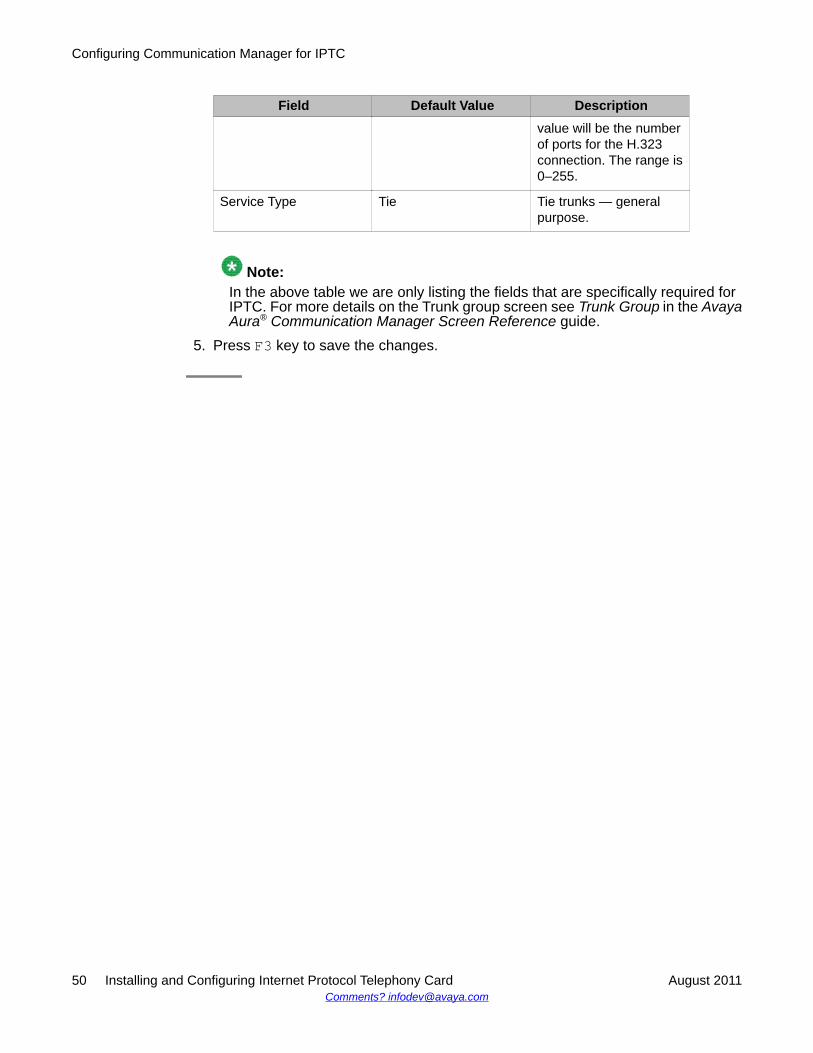
Field Default Value Descriptionvalue will be the numberof ports for the H.323connection. The range is0–255.
Service Type Tie Tie trunks — generalpurpose.
Note:In the above table we are only listing the fields that are specifically required forIPTC. For more details on the Trunk group screen see Trunk Group in the AvayaAura® Communication Manager Screen Reference guide.
5. Press F3 key to save the changes.
Configuring Communication Manager for IPTC
50 Installing and Configuring Internet Protocol Telephony Card August 2011Comments? [email protected]

Index
A
activating the card ......................................................33add an IPTC ...............................................................32add IP codec set .........................................................43add IP network region ................................................45architecture ..................................................................7
B
backplane .....................................................................7backup switch database .............................................16
C
Card Indicators .............................................................9configure an IPTC ......................................................37configure IP Signaling group ......................................38configure NFS ............................................................25configure the Ethernet ................................................25configure the IPTC .....................................................31copy disc to dialer .......................................................17
D
deleting a card ............................................................35diagnostic ...................................................................40
E
Ethernet port ................................................................9
F
function .........................................................................8
H
hot plug-in ...................................................................11
I
installing ENBC ISDN/PRI option ...............................27IPTC Card ....................................................................7IPTC with Communication Manager ...........................43
L
LED operation descriptions ..........................................9LEDs ............................................................................9loading ENBC software ..............................................21
O
Out Of Service ............................................................34
P
PG230 ..........................................................................7
R
red, green, yellow LEDs ...............................................9restore switch database .............................................28run installation utilities. ...............................................19
S
Shut down the switch .................................................18signaling group ...........................................................46switch component compatibility ..................................13
T
terminate the installation ............................................29trunk group .................................................................48Tunr on the switch ......................................................19
U
upgrade ENBC generic option ....................................15upgrade ENBC software .............................................19upgrading the ENBC software ....................................24using IPTC with PG230RM .........................................11
Installing and Configuring Internet Protocol Telephony Card August 2011 51


![[1]Oracle® Fusion Middleware Installing and Configuring ... · Installing and Configuring Oracle Enterprise Data Quality 12c ... Oracle Fusion Middleware Installing and Configuring](https://static.fdocuments.net/doc/165x107/5b8396637f8b9a47588d872b/1oracle-fusion-middleware-installing-and-configuring-installing-and.jpg)