TC151ClearancesofWires,Conductors,Cables,andEquipmentfrom ...

Nual® BraNdInstaller’s guIde for wIre and cables

Contact General Cable toll-free at (800) 661-1451 www.nual.com 32
This guide is intended to provide introductory technical data to aid in the correct selection of wire and cable for permanent installation in commercial, institutional and industrial premises. Such installations are governed by the requirement of the Canadian Electrical Code Part I, and enforced by the appointed authority having jurisdiction in this area under provincial law (federal law in the case of federal territories), with or without Code amendments as the case may be.
Wires and cables in installations falling under the jurisdiction of the provincial and territorial inspection authorities are almost invariably required to be certified to the requirements of CSA standards under the approval of the CSA group.
This guide provides information on standard products stocked by General Cable’s distributors. General Cable also manufactures a wide range of additional products in various sizes which can be supplied by special order.
For more information, contact your distributor or visit www.nual.com for the most current list of product offerings.
Wire and cable products supplied by General Cable comply with the codes, standards and product specifications as indicated in this guide.
Weights and measurements are subject to manufacturing tolerances and product design changes. Consequently, General Cable does not accept responsibility for costs incurred by a purchase as a result of weights and measurements not conforming exactly to those indicated.
About This Guide

Contact General Cable toll-free at (800) 661-1451 www.nual.com 54
About General Cable
General Cable is a name people know and trust. For over a century, our products have helped supply communities with power from coast to coast across the continent. And in that time we’ve become synonymous not only with aluminum, but with the latest technology and highest standards of quality and service.
We offer a full range of bare and insulated wires to both the utility and distribution markets, and support them with technical experts specifically trained to help our customers achieve their desired end results.
We believe our customers’ satisfaction relies entirely on the quality of our products. That’s why we work hard to ensure they are consistently superior to anything else on the market. Our distribution centre, technical centre and manufacturing facilities have attained ISO certifications 9001-2008 (Quality Management System) and 14001 (Environmental Management System) and OHSAS certification
18001 (Occupational Health & Safety Management).
We’re committed to the success of our products, and to the satisfaction of our customers. That’s why General Cable will continue to be a name people know and trust.
We believe our
customers’
satisfaction relies
entirely on the
quality of our
products.

Contact General Cable toll-free at (800) 661-1451 www.nual.com 76
Table of Contents
Engineering Information/NUAL® Brand ................................................................... 8General Cable Armoured Cables ............................................................................. 10Fire Test Standards/FT1 and FT4 Rating ................................................................. 16Splicing and Terminating Conductors ...................................................................... 18Single- vs Multi-conductor Constructions .............................................................. 22Installation of Single-conductor AC90, ACWU90 & TECK90 Cables ................... 26Recommended Configuration for Parallel Operation of Single-conductor Cables in Free Air ............................................30-31
Allowable AmpacitiesDiagram 1 ...................................................................................................................... 32Table 5-5 ....................................................................................................................... 34Table 5-6 ...................................................................................................................... 36Diagram 2 ..................................................................................................................... 38Table 5-7 ....................................................................................................................... 40Table 5-8 ........................................................................................................................ 42Diagram 3 ...................................................................................................................... 44Table 5-9 ........................................................................................................................ 46Table 5-10 ...................................................................................................................... 48Diagram 4 ...................................................................................................................... 50Table 5-11 ...................................................................................................................... 52Table 5-12 ...................................................................................................................... 54Notes and Corrections to Tables 5-5 to 5-12 ........................................................... 56
Application RulesSection 4: ConductorsRule 4-004: Ampacity of Wires and Cables ............................................................ 60
Rule 4-006: Temperature Limitations ....................................................................... 64
Rule 4-010: Induced Voltages and Currents in Metal Sheath Armour or Sheaths of Single-conductor Cables ................................................................ 64
Section 8: Circuit Loading and Demand FactorsRule 8-100: Current Calculations ............................................................................... 65Rule 8-102: Voltage Drop ............................................................................................ 65Rule 8-104: Maximum Circuit Loading ...................................................................... 66Rule 8-106: Use of Demand Factors.......................................................................... 67
Section 12: Wiring MethodsRule 12-012: Underground Installations .................................................................. 68Rule 12-106: Multi- and Single-conductor Cables ................................................. 69Rule 12-108: Conductors in Parallel .......................................................................... 70Rule 12-118: Termination and Splicing of Aluminum Conductors ............................................................................ 71Rules 12-600 – 12-618: Armoured Cable Work Rules ............................................. 72Rules 12-2200 – 12-2210: Cables in Trays................................................................. 75
TablesConductor Ampacities ............................................................................................... 80Table 5A: Correction Factors ..................................................................................... 84Tables 5B/5C: Correction Factors .............................................................................. 86Table 5D: Current Rating Correction Factors .......................................................... 87Table 8: Percent Conduit and Tubing Fill .................................................................. 87Table 9: Cross-sectional Areas of Conduit and Tubing ......................................... 88Table 10A: Dimensions of Cable ................................................................................ 90Table 10B: Dimensions of Photovoltaic Cable ........................................................ 94Table 16: Minimum Size Conductors for Bonding .................................................. 98Table 18: Minimum Size of Grounding Conductor for Service Raceway and Service Equipment .............................................................. 99Table 21: Supporting of Conductors in Vertical Runs of Raceways .................................................................................... 99Dimensions of Stranded Aluminum Conductors .................................................. 100DC Resistance Values of Stranded Conductors ................................................... 102Table D6: Tightening Torques ................................................................................... 106Table D7: Tightening Torques .................................................................................. 109 Basic Metric Conversion Factors .......................................................................... 112Notes Pages .......................................................................................................113-119
Contact General Cable toll-free at (800) 661-1451 www.nual.com 98
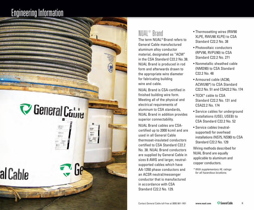
NUAL® BrandThe term NUAL® Brand refers to General Cable manufactured aluminum alloy conductor material, designated as “ACM” in the CSA Standard C22.2 No. 38. NUAL Brand is produced in rod form and afterwards drawn to the appropriate wire diameter for fabricating building wire and cable.
NUAL Brand is CSA-certified in finished building wire form. Meeting all of the physical and electrical requirements of aluminum to CSA standards, NUAL Brand in addition provides superior connectability.
NUAL Brand cables are CSA-certified up to 2000 kcmil and are used in all General Cable thermoset-insulated conductors certified to CSA Standard C22.2 No. 38. NUAL Brand conductors are supplied by General Cable in sizes 8 AWG and larger, neutral-supported cables which have AA-1350 phase conductors and an ACSR neutral/messenger conductor that is manufactured in accordance with CSA Standard C22.2 No. 129.
• Thermosetting wires (RW90 XLPE, RWU90 XLPE) to CSA Standard C22.2 No. 38
• Photovoltaic conductors (RPV90, RVPU90) to CSA Standard C22.2 No. 271
• Nonmetallic sheathed cable (NMD90) to CSA Standard C22.2 No. 48
• Armoured cable (AC90, ACWU90*) to CSA Standard C22.2 No. 51 and CSA22.2 No. 174
• TECK* cable to CSA Standard C22.2 No. 131 and CSA22.2 No. 174
• Service cables for underground installations (USEI, USEB) to CSA Standard C22.2 No. 52
• Service cables (neutral-supported) for overhead installations (NS75, NS90) to CSA Standard C22.2 No. 129
Wiring methods described for NUAL Brand are equally applicable to aluminum and copper conductors.
* With supplementary HL ratings for all hazardous locations.
Engineering Information

Contact General Cable toll-free at (800) 661-1451 www.nual.com 1110
General Cable Armoured Cables
AC90
Available Sizes NUAL® Brand Specifications
Single-conductorMulti-conductor
General Cable AC90 Single-conductor Cable General Cable AC90 Multi-conductor Cable
NUAL BrandPhaseConductor
NUAL BrandPhaseConductor
Concentric NUAL Brand Bonding Conductor
NUAL Brand Bonding Conductor
Interlocked Aluminum Armour
Interlocked Aluminum Armour
XLPEInsulation(Rated -40°C to 90°C)
XLPEInsulation(Rated -40°C to 90°C)
1/0 AWG to 2000 kcmil6 AWG to 750 kcmil
CSA C22.2 No. 51Suitable for use in cable tray in dry locations
Paper Core Wrap

Contact General Cable toll-free at (800) 661-1451 www.nual.com 1312
General Cable Armoured Cables
ACWU90
Single-conductorMulti-conductor
General Cable ACWU90 Single-conductor Cable General Cable ACWU90 Multi-conductor Cable
NUAL BrandPhaseConductor
NUAL BrandPhaseConductor
Concentric NUAL Brand Bonding Conductor
FT4-rated, AG14PVC Jacket FT4-rated, AG14
PVC Jacket
NUAL Brand Bonding Conductor
Interlocked Aluminum Armour
Interlocked Aluminum Armour
XLPEInsulation(Rated -40°C to 90°C)
XLPEInsulation(Rated -40°C to 90°C)
1/0 AWG to 2000 kcmil6 AWG to 750 kcmil
CSA C22.2 No. 51FT4-Rated: Vertical Cable Tray TestCSA C22.2 No. 174 Hazardous Locations
Available Sizes SpecificationsNUAL Brand
Paper Core Wrap

Contact General Cable toll-free at (800) 661-1451 www.nual.com 1514
General Cable Armoured Cables
TECK90
Single-conductorMulti-conductor
General Cable TECK90 Single-conductor Cable General Cable TECK90 Multi-conductor Cable
NUAL BrandPhaseConductor NUAL Brand
PhaseConductor
Concentric NUAL Brand Bonding Conductor
FT4-rated, AG14PVC Jacket FT4-rated, AG14
PVC Jacket
NUAL Brand Bonding Conductor Interlocked
Aluminum Armour
Interlocked Aluminum Armour
XLPEInsulation(Rated -40°C to 90°C)
XLPEInsulation(Rated -40°C to 90°C) 90˚C AG14
PVC inner jacket
90˚C AG14PVC inner jacket
Nonhygroscopicfiller
1/0 AWG to 1000 kcmil6 AWG to 750 kcmil
CSA C22.2 No. 131 (TECK)CSA C22.2 No. 174 (Hazardous Locations)FT4-Rated: Vertical Cable Tray Test
Available Sizes SpecificationsNUAL Brand

Contact General Cable toll-free at (800) 661-1451 www.nual.com 1716
Fire Test Standards
FT1 and FT4 RatingsThe CSA Standard for AC90, ACWU90 and TECK90 cables requires that all cables meet the Vertical Flame Test (FT1 Bunsen burner test) to CSA Standard C22.2 No. 2556. In addition, a much tougher level of performance is specified in the Vertical Flame Test – Cables in Cable Tray to CSA Standard C22.2 No. 2556.
All General Cable ACWU90 and TECK90 conductors meet both these levels of flammability performance. Compliance is indicated by the designation “FT4” printed on the outer PVC jacket and on shipping tags.
PVC-jacketed cables meeting the FT4 standard are accepted by the National Building Code for installation in all parts of noncombustible buildings, including vertical shafts and return air plenums. The 2012 Canadian Electrical Code Part I reflects an equivalent performance level requirement, harmonizing the two major installation codes.
Note: Check with your provincial building code officials to ensure compliance with local amendments.
The unjacketed construction, type AC90, is not required to meet the FT4 test, but is fully compliant. Its interlocked aluminum armour is considered equivalent to insulated conductors in metal conduit and is highly resistant to flame spread.
Appendix “B”, Rule 2-126 of the CEC explains the application of cables bearing the FT1 and FT4 designations.
FT1 – Wires and cables that are suitable for installation in buildings of combustible construction
FT4 – Wires and cables that are suitable for installation in:
(a) buildings of noncombustible and combustible construction; and (b) spaces between a ceiling and floor, or ceiling and roof, that may be used as a plenum in buildings of combustible or noncombustible construction. Wires and cables with
combustible insulation, outer jackets or sheaths that do not meet the above classifications should be located in enclosed noncombustible raceways, masonry walls or concrete slabs.
Wire and cable passing these tests will be marked FT1 or FT4 directly on their jackets. They will be suitable for installation in buildings as shown above.
Rule 2-126 and Appendix B and G of the Canadian Electrical Code Part I, Twenty-second Edition, 2012, provides cross-reference to the National Building Code of Canada.
NOTICEPurchasers, installers and end-users of cables with nonmetallic coverings should note the following:
WARNINGFLAMMABLE: Nonmetallic coverings of electric cable will burn and may transmit fire when ignited.
TOXIC: Burning nonmetallic coverings may emit acid gases which are highly toxic, and dense smoke.
CORROSIVE: Emission of acid gases may corrode metal in the vicinity, such as sensitive instruments and reinforcing rods in concrete.

Contact General Cable toll-free at (800) 661-1451 www.nual.com 1918
Typical examples are 1) in service entrances, in both single- and multi-conductor constructions, where the neutral conductor also serves as the ground path, and 2) in single-conductor feeders rated over 425 amps, where the bonding circuit is discontinuous in order to avoid sheath circulating currents. Care must be taken to seal the cable ends properly and to solidly bond the armour and bonding conductor wires at the other end of the cable using an AL9CU or AL7CU-rated connector bolted to the equipment enclosure.
Splicing and Terminating Conductors
Care should be taken to ensure
service continuity.
Note: Lugs and connectors for NUAL Brand conductors are typically certified to CSA 22.2 No. 65.
General When splicing and terminating either an aluminum or copper conductor, care should be taken to ensure service continuity. General Cable recommends the following procedures for all cable connections:
1. FittingsUse only terminal lugs and connectors certified and marked “AL9CU” and “AL7CU” which are suitable for both aluminum and copper. If the equipment is not approved for aluminum, an approved adapter may be used.
2. InsulationRemove insulation from the conductor in a manner that avoids nicking, ringing or otherwise damaging the conductor.
3. CleaningWire brush the exposed conductor end to remove any oxide film. Coat with a suitable joint compound to inhibit its reformation, thus protecting the contact surfaces from air and moisture.
4. InstallationInsert the prepared cable end into the connector or terminal lug and secure the connection. Ensure that the correct tool, die and compression sequence are used for compression fittings and that appropriate torque is applied to all threaded hardware including bolted and mechanical set screw type connectors.
5. Binding Head ScrewsWhen connecting solid conductor with a binding head screw, make a 3/4 loop under the screw head and secure.
Outdoor Armoured Cable TerminationsFor outdoor terminations on General Cable's ACWU90 and TECK90 cables such as connections to overhead lines or outdoor bus, or where it is permitted to discontinue the bonding conductor, we recommend the method shown on page 20.

Contact General Cable toll-free at (800) 661-1451 www.nual.com 2120
3
2
1
Splicing and Terminating Conductors
Single-conductor Cables
1. Strip back armour and PVC jacket.
2. Fold the bonding conductor strands back over the armour.
3. Waterproof the whole termination by using CSA- approved wet-rated heat shrink tubing.
Multi-conductor Cables
1. Follow step 1 above.
2. Cut off the bonding conductor flush with the armour.
3. Follow step 3 above.
Note: Care must be taken to seal the exposed conductor by taping it with a self-sealing rubber tape or heat shrink tubing. The goal is to prevent water getting inside the insulation and the cable assembly.
Services Above & Below GroundGeneral Cable type ACWU90 and TECK90 cable may be used for services both in the single-and multi-conductor form. Single-conductor services should have all the bonding conductor wires attached to a common lug bolted to the service equipment using a AL9CU connector.
Parallel CircuitsFor very large loads it is sometimes economical to parallel two or more cables. When this is done, we strongly recommend that the lengths, size and construction of the cables and connectors be identical. Refer to Code Rule 12-108 for CEC requirements for parallel conductors. In order to obtain reasonably good load-sharing among the single-conductor cables, it is important that the impedance of each cable be almost identical to that of the other cables of the same phase, and for this reason we recommend the configurations shown on pages 30-31.
3
2
1

Contact General Cable toll-free at (800) 661-1451 www.nual.com 2322
GeneralIt is well known and understood that installations of armoured cable are more economical than pipe and wire installations. This is due largely to the fact that the activities of conduit installation and wire pulling are not required with armoured cable. Armoured cables are readily available in single-and multi-conductor constructions. There are various aspects that should be taken into consideration when choosing between these two. The attractions of first-cost savings of single-conductor cable may need to be tempered with other technical considerations. The first-cost savings may be much less than they first appear, and the integrity of the circuit is subject to some potential pitfalls.
• The cost savings from smaller conductors, sized in accordance with Tables 1 and 3 of the code, are diminished by increased armour, bonding conductor, or metal sheath, extra jacket cost, and the addition of an external bonding conductor in large single-conductor cables.
• The 70% derating for single-conductors may call for a higher equipment and cable cost than expected, when compared with the 80% derating for multi-conductor cables. (Code Rule 8-104).
• When comparing single-conductor to multi-conductor cables, fully account for the end-user energy conservation needs, and ensure that all code rules, equipment limitations and health concerns have been fully addressed.
Some of these technical concerns are outlined below. If assistance is needed, do not hesitate to contact your nearest General Cable sales office.
Cost of MaterialRecent analyses demonstrate that multi-conductor armoured cables can be more cost-effective than single-conductor constructions for many installations. While single-conductors can often save first- costs, due to higher ampacity ratings, this advantage is partially offset by the extra cost
of additional armour or sheath on singles as compared to only one on multi-conductor cable.
Cost of LabourLabour is often higher in single-conductor installations. Each phase being an individual cable requires all the same handling procedures as multi-conductor cables which contain all of the phases.
Voltage DropA further effect of single-conductors in longer feeder circuits can be increased voltage drop. This arises not only on account of the higher resistance of the smaller conductors, but also on account of the increased spacing between conductors in single-conductor systems. It is a fact that greater spacing increases impedance and inductive reactance, which is the main contribution to voltage drop. The tables presented in the Code appendices are nominal ampacities which in no way account for voltage drop.
Single- vs. Multi-Conductor Constructions

Contact General Cable toll-free at (800) 661-1451 www.nual.com 2524
General Cable provides upon request a program which can be used for precise calculation of voltage drop.
Magnetic Fields and HarmonicsThe magnetic fields surrounding single-conductors can extend much farther than those surrounding multi-conductor cables. The nuisance effects of the magnetic fields can be both elusive and expensive to correct. Typical nuisance effects involve the actions of the magnetic fields on sensitive electronic equipment, such as computers. In extreme cases, shielding and filtering of power supplies may be the only way to remedy the situation.
The magnetic field from each conductor is cancelled by those of the neighbouring conductors in a three-phase system with a pure sine wave form. In a four-conductor cable, the magnetic fields neutralize almost totally within the cable. However, the fields of single-conductors can extend much farther,
depending on the spacing between the conductors.
Magnetic fields are amplified in circuits with high levels of third harmonic currents and multiples of the third harmonic. These currents are common today due to electronic devices which chop the wave form of the voltage. One of the unexpected results is that third harmonic magnetic fields in each of the three phases are additive, so the magnetic field surrounding a group of three conductors can be much greater than would be expected. This amplified magnetic field is cancelled only by the field from the neutral conductor. In large single-conductor feeders, the neutral conductor is often located a significant distance from some of the phase conductors, leading to propagation of third harmonic magnetic fields to greater distances. The use of multi-conductor cables will eliminate this concern, owing to their close proximity.
Special precautions are necessary with single-
conductor systems, in addition to those previously mentioned. Accessories which totally surround single-conductor cables, such as clamps and connectors, must be non-ferrous to avoid magnetic hysteresis and eddy current losses, which could lead to serious overheating. Third harmonic currents will greatly increase the magnetic losses in such components. The current sharing between parallel conductors of the same phase must be ensured by attention to phase configurations. Sometimes imbalances in the current sharing can be present due to inherent difficulties in complying with spacing requirements. It is virtually impossible to balance the third harmonic currents equally with any type of single-conductor phase configuration, although this is automatically achieved with four-conductor cables.
Circulating CurrentsAn explanation of circulating currents in metallic sheaths and armour of single-conductor
cables, including their causes and effects, is provided in the Appendix B notes to Rule 4-010 of the 2012 Canadian Electrical Code Part I. They can be prevented by rigid attention to methods explained in the following pages.
Single- vs. Multi-Conductor Constructions

Contact General Cable toll-free at (800) 661-1451 www.nual.com 2726
Installation of Single-Conductor Cables: AC90, ACWU90 & TECK90
1
2
1
2
Aluminum Plate Aluminum Plate
Circuits Rated Up to 425 Amps InclusiveOn any AC system, currents flowing in the center conductor will induce small currents in the concentrically applied bonding wires and in the interlocked armour. For circuit ampacities up to and including 425 amps these induced currents do not affect the cable ampacity and may be neglected. We recommend terminating the cables as follows: the bonding wires of all cables entering the equipment enclosure should be bunched and connected to the bonding screw of the terminal; (2) the armour of each cable should be attached to the entry plate by means of an approved connector, and the entry plate should be aluminum or some other nonmagnetic conducting material (1).
Circuits Rated Up to 425 Amps Inclusive
Note: In the 2012 Canadian Electrical Code Part 1, Rule 4-010 has added direction regarding single-conductor cables carrying more than 200 amps. See the full text under "Application Rules" in this handbook.
Contact General Cable toll-free at (800) 661-1451 www.nual.com 2928
Note: In the 2012 Canadian Electrical Code Part 1, Rule 4-010 has added direction regarding single-conductor cables carrying more than 200 amps. See the full text under "Application Rules" in this handbook.
Installation of Single-Conductor Cables: AC90, ACWU90 & TECK90
Circuits Rated Over 425 Amps
3 5Aluminum Plate Fibre Plate Non-conducting
6
4
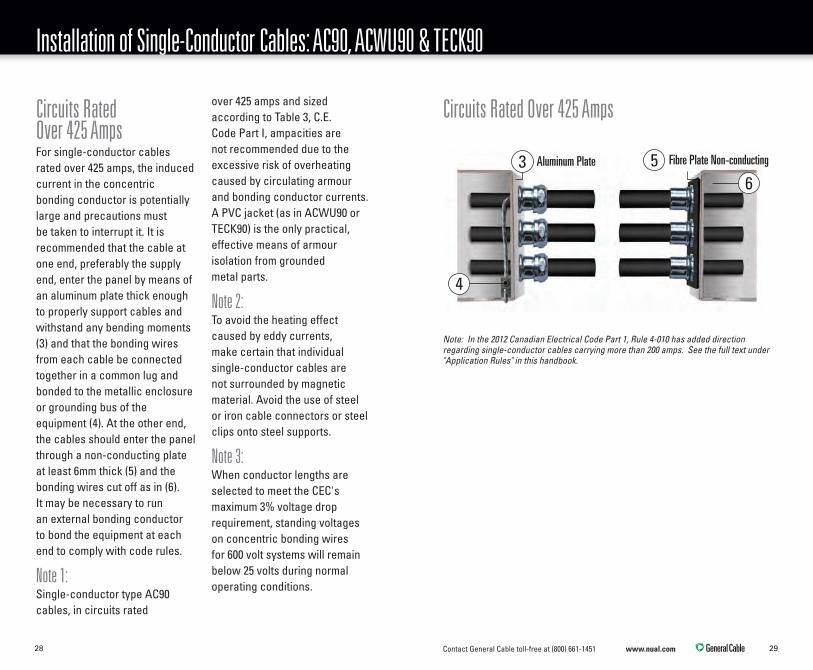
Circuits Rated Over 425 AmpsFor single-conductor cables rated over 425 amps, the induced current in the concentric bonding conductor is potentially large and precautions must be taken to interrupt it. It is recommended that the cable at one end, preferably the supply end, enter the panel by means of an aluminum plate thick enough to properly support cables and withstand any bending moments (3) and that the bonding wires from each cable be connected together in a common lug and bonded to the metallic enclosure or grounding bus of the equipment (4). At the other end, the cables should enter the panel through a non-conducting plate at least 6mm thick (5) and the bonding wires cut off as in (6). It may be necessary to run an external bonding conductor to bond the equipment at each end to comply with code rules.
Note 1: Single-conductor type AC90 cables, in circuits rated
over 425 amps and sized according to Table 3, C.E. Code Part I, ampacities are not recommended due to the excessive risk of overheating caused by circulating armour and bonding conductor currents. A PVC jacket (as in ACWU90 or TECK90) is the only practical, effective means of armour isolation from grounded metal parts.
Note 2: To avoid the heating effect caused by eddy currents, make certain that individual single-conductor cables are not surrounded by magnetic material. Avoid the use of steel or iron cable connectors or steel clips onto steel supports.
Note 3: When conductor lengths are selected to meet the CEC's maximum 3% voltage drop requirement, standing voltages on concentric bonding wires for 600 volt systems will remain below 25 volts during normal operating conditions.

Contact General Cable toll-free at (800) 661-1451 www.nual.com 3130
A B C A B
A Bx Cx x N A Bxx Cx x xN A Bx Cx x N
x x 3x x A Bx Cx3xCx
OR
B Cx D DA
B Cx
A
B Cx
x xxx xxA
OR
*
*
Recommended Configuration for Parallel Operation of Single-Conductor Cables in Free Air
Single Phase Three Phase
Two Conductors per Phase
Two Conductors per Phase
Three Conductors per Phase*
Three Conductors per Phase*
Four conductors per Phase
Four Conductors per Phase
N A B
A B N
A B N
B A N
x x
x x
x x
x x x x x
OR
A B Nx x 3x A B Nx x 3x A B Nx x *
A B
A B N
A B N
B A N
x
x x
x B
Bx
x A
Ax
x x N
Nx
x
x
Nx
Nx
x
x x x x A B B Ax x xxNx
OR
* Precise load sharing is difficult with three conductors per phase and the configurations shown represent the most practical compromise.
General Cable strongly recommends the use of one-, two-or four-conductors per phase due to the ease of achieving equal current sharing in practical installations.
Note: (1) Neutral conductors may be located
outside the above groups in the most convenient manner or as shown.
(2) Not all the configurations shown provide precisely equal load sharing. The imbalance is decreased as the separation of the groups is increased relative to the spacing of conductors within the group.
X = One cable diameter (above ground).A,B,C = Phase conductor designation.N = Neutral conductor designation.
D = Separation of groups equal to width of one group.
X = One cable diameter (above ground).A,B,C = Phase conductor designation.N = Neutral conductor designation.
A B
A B
C B
C C B
x
x
x C
Ax
x
x
x N
N
x N
x
x x x x N NxxAx
OR
N Bx Cx
x x x x
DA
C Bx
AOR
B Cx D DA
B Cx
A
C Bx
x xxx x
D C Bx
Axxx
A
OR
OR
A B C C Bx
x x
x
A B Cx x
x x N NxxAx
Ax
C Bx x x
A
x
Cx
Bx
A
x
Bx
Cx
A
B C C Bx x x x N NxxAx

Contact General Cable toll-free at (800) 661-1451 www.nual.com 3332
Diagram 1
Note: All dimensions in mm.
Applicable Installation Configurations for Single-Conductors Directly Buried in the Earth
190 190
915
DETAIL 1: 1 cable per phase
190 190 190 190 190
915
DETAIL 2: 2 cables per phase
190 190 190 190 190
190
915
DETAIL 4: 4 cables per phase
190190 610 190 190
915
DETAIL 3: 2 cables per phase
190190 610 190 190
190
915
DETAIL 5: 4 cables per phase
190 190 190 190 190
190
190
915
DETAIL 6: 6 cables per phase
190190 610 190 190
190
190
915
DETAIL 7: 6 cables per phase190 190
915
DETAIL 1: 1 cable per phase
190 190 190 190 190
915
DETAIL 2: 2 cables per phase
190 190 190 190 190
190
915
DETAIL 4: 4 cables per phase
190190 610 190 190
915
DETAIL 3: 2 cables per phase
190190 610 190 190
190
915
DETAIL 5: 4 cables per phase
190 190 190 190 190
190
190
915
DETAIL 6: 6 cables per phase
190190 610 190 190
190
190
915
DETAIL 7: 6 cables per phase
190 190
915
DETAIL 1: 1 cable per phase
190 190 190 190 190
915
DETAIL 2: 2 cables per phase
190 190 190 190 190
190
915
DETAIL 4: 4 cables per phase
190190 610 190 190
915
DETAIL 3: 2 cables per phase
190190 610 190 190
190
915
DETAIL 5: 4 cables per phase
190 190 190 190 190
190
190
915
DETAIL 6: 6 cables per phase
190190 610 190 190
190
190
915
DETAIL 7: 6 cables per phase

Contact General Cable toll-free at (800) 661-1451 www.nual.com 3534
Table 5-5
Size, AWGor kcmil
1/PhaseDetail 1
2/PhaseDetail 2
2/PhaseDetail 3
4/PhaseDetail 4
4/PhaseDetail 5
6/PhaseDetail 6
6/PhaseDetail 7
9A 8A 9A 8A 9A 8A 9A 8A 9A 8A 9A 8A 9A 8A
1/0 190 245 190 245 190 245 158 203 171 220 129 165 140 179
2/0 220 285 220 285 220 285 178 229 193 248 145 186 157 202
3/0 255 330 255 330 255 330 201 258 218 280 163 210 178 228
4/0 300 385 300 385 300 385 227 291 246 315 183 236 200 256
250 330 425 328 421 330 425 247 317 267 343 200 256 217 278
350 415 530 390 500 410 520 292 375 318 408 237 304 258 331
500 515 660 471 605 495 630 352 452 383 489 284 365 309 396
600 585 740 513 659 541 682 382 491 419 534 308 397 340 433
750 665 845 580 745 610 775 431 554 469 596 348 447 379 482
1000 780 980 659 846 710 890 488 627 542 683 393 505 437 551
1250 868 1083 750 935 790 985 554 691 604 753 446 556 487 607
1500 952 1176 821 1011 865 1068 605 746 660 813 487 600 531 655
1750 1027 1257 880 1078 932 1140 647 793 706 865 520 637 568 696
2000 1094 1325 934 1133 991 1200 686 832 749 909 552 669 602 730
The ampacities of this table are those contained in Tables D8A and D9A of the Canadian Electrical Code Part I, 22nd Edition, 2012.
Ampacities are based on 90°C conductor temperature, 20°C ambient earth temperature, configurations of Diagram 1, and the following conditions:
(a) For any load, the cable terminates at equipment of any type other than a fusible switch or circuit breaker; or
(b) The load is NON-CONTINUOUS and either end of the cable terminates at a fusible switch or circuit breaker.
Allowable Ampacities for Single-Conductor Cable Directly Buried in the Earth – Non-Continuous Loads (See Diagram 1)

Contact General Cable toll-free at (800) 661-1451 www.nual.com 3736
Table 5-6
Size, AWG
or kcmil
1/PhaseDetail 1
2/PhaseDetail 2
2/PhaseDetail 3
4/PhaseDetail 4
4/PhaseDetail 5
6/PhaseDetail 6
6/PhaseDetail 7
9B 8B 9B 8B 9B 8B 9B 8B 9B 8B 9B 8B 9B 8B
100% 80% 100% 80% 100% 80% 100% 80% 100% 80% 100% 80% 100% 80% 100% 80% 100% 80% 100% 80% - - 100% 80% 100% 80%
1/0 162 133 208 172 162 133 208 172 162 133 208 172 158 133 203 172 162 133 208 172 129 165 140 133 179 172
2/0 187 154 242 200 187 154 242 200 187 154 242 200 178 154 229 200 187 154 242 200 145 186 157 154 202 200
3/0 217 179 280 231 217 179 280 231 217 179 280 231 201 179 258 231 217 179 280 231 163 210 178 228
4/0 255 210 327 270 255 210 327 270 255 210 327 270 227 210 291 270 246 210 315 270 183 236 200 256
250 281 231 361 298 281 231 361 298 281 231 361 298 247 231 317 298 267 231 343 298 200 256 217 278
350 353 291 450 371 353 291 450 371 353 291 450 371 292 291 375 371 318 291 408 371 237 304 258 331
500 438 361 561 462 438 361 561 462 438 361 561 462 352 452 383 361 489 462 284 365 309 396
600 498 410 629 518 498 410 629 518 498 410 629 518 382 491 419 410 534 518 308 397 340 433
750 570 469 718 592 570 469 718 592 570 469 718 592 431 554 469 596 592 348 447 379 482
1000 680 560 850 700 659 560 846 700 680 560 846 700 488 627 542 683 393 505 437 551
1250 770 634 960 791 750 634 935 791 770 634 935 791 554 691 604 753 446 556 487 607
1500 867 714 1071 882 821 714 1011 882 865 714 1011 882 605 746 660 813 487 600 531 655
1750 956 788 1165 959 880 788 1078 959 932 788 1078 959 647 793 706 865 520 637 568 696
2000 1037 854 1250 1029 934 854 1133 1029 991 854 1133 1029 686 832 749 909 552 669 602 730
The ampacities of this table are those contained in Tables D8B and D9B of the Canadian Electrical Code Part I, 22nd Edition, 2012.
Ampacities are based on 90°C conductor temperature, 20°C ambient earth temperature, configurations of Diagram 1, and the following conditions:
(a) The load is CONTINUOUS, and
(b) either end terminates at a fusible switch or circuit breaker.
The columns with the heading 80% denote that equipment identified in (b) above is not marked as certified to carry its nameplate ampere rating continuously.
The columns with the heading 100% denote that equipment identified in (b) above is marked as certified to carry its nameplate ampere rating continuously.
Allowable Ampacities for Single-Conductor Cable Directly Buried in the Earth – Continuous Loads (See Diagram 1)
Contact General Cable toll-free at (800) 661-1451 www.nual.com 3938
480
190
190
760
480
690
190190
760
290
DETAIL 1: 1 conductor per phase
450
190
190
190
760
640
640
190190
190
760
450
DETAIL 2: 2 conductors per phase
190 190 190
1200
190 190
190
190
760
640
DETAIL 4: 6 conductors per phaseDETAIL 3: 4 conductors per phase
640
190190
190
190
190
760
830 OR
OR OR
760
190190 190
830
190
190
640
480
190
190
760
480
690
190190
760
290
DETAIL 1: 1 conductor per phase
450
190
190
190
760
640
640
190190
190
760
450
DETAIL 2: 2 conductors per phase
190 190 190
1200
190 190
190
190
760
640
DETAIL 4: 6 conductors per phaseDETAIL 3: 4 conductors per phase
640
190190
190
190
190
760
830 OR
OR OR
760
190190 190
830
190
190
640
Diagram 2
Note: All dimensions in mm.
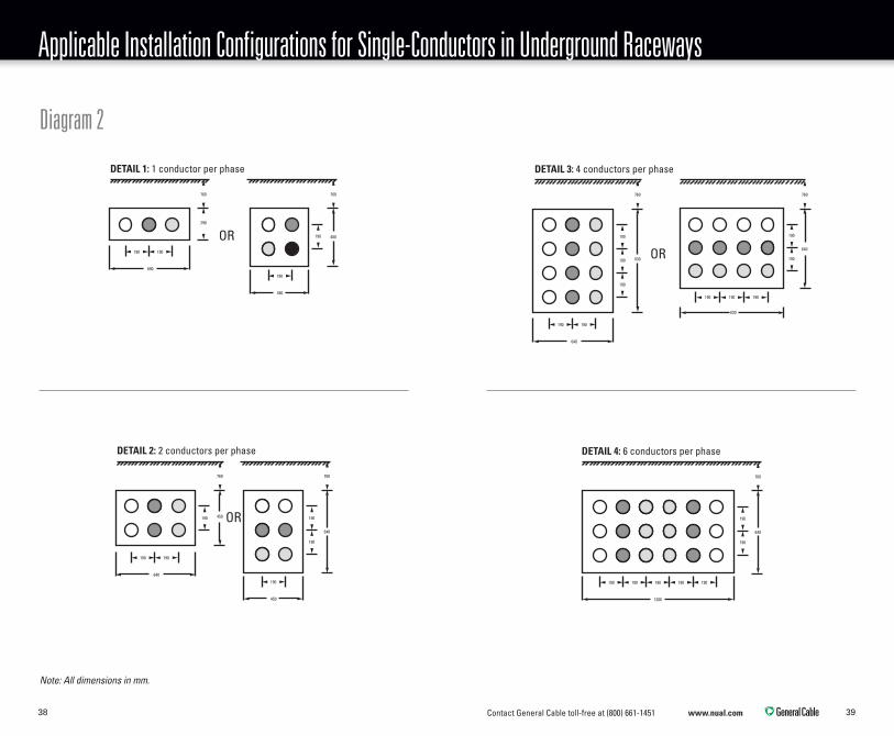
Applicable Installation Configurations for Single-Conductors in Underground Raceways

Contact General Cable toll-free at (800) 661-1451 www.nual.com 4140
Table 5-7
Size, AWGor kcmil
1/PhaseDetail 1
2/PhaseDetail 2
4/PhaseDetail 3
6/PhaseDetail 4
11A 10A 11A 10A 11A 10A 11A 10A
1/0 180 231 157 201 123 159 114 146
2/0 205 264 178 228 140 180 128 164
3/0 235 301 203 260 158 204 145 186
4/0 269 345 231 296 180 231 164 211
250 296 379 253 325 197 252 179 230
350 360 461 306 391 236 303 213 275
500 442 564 372 475 283 364 257 330
600 488 621 409 521 314 404 284 365
750 556 706 464 589 349 448 315 406
1000 653 823 541 682 409 526 370 474
1250 738 920 608 759 457 571 413 515
1500 813 1004 667 824 501 618 452 556
1750 880 1077 719 880 538 659 484 592
2000 940 1139 766 928 571 692 513 622
The ampacities of this table are those contained in Tables D10A and D11A of the Canadian Electrical Code Part I, 22nd Edition, 2012.
Ampacities are based on 90°C conductor temperature, 20°C ambient earth temperature, configurations of Diagram 2 and the following conditions:
(a) For any load, the cable terminates at equipment of any type other than a fusible switch or circuit breaker; or
(b) The load is NON-CONTINUOUS and either end of the cable terminates at a fusible switch or circuit breaker.
Allowable Ampacities for Single-Conductor Cable in Underground Raceways –Non-Continuous Loads (See Diagram 2)

Contact General Cable toll-free at (800) 661-1451 www.nual.com 4342
Table 5-8
Size, AWGor kcmil
1/PhaseDetail 1
2/PhaseDetail 2
4/PhaseDetail 3
6/PhaseDetail 4
11B 10B 11B 10B 11B 10B 11B 10B
100% 80% 100% 80% 100% 80% 100% 80% - - - -
1/0 162 133 208 172 157 133 201 172 123 159 114 146
2/0 187 154 242 200 178 154 228 200 140 180 128 164
3/0 217 179 280 231 203 179 260 231 158 204 145 186
4/0 255 210 327 270 231 210 296 270 180 231 164 211
250 281 231 361 298 253 231 325 298 197 252 179 230
350 353 291 450 371 306 291 391 371 236 303 213 275
500 438 361 561 462 372 361 475 462 283 364 257 330
600 488 410 621 518 409 521 518 314 404 284 365
750 556 469 706 592 464 589 349 448 315 406
1000 653 560 823 700 541 682 409 526 370 474
1250 738 634 920 791 608 759 457 571 413 515
1500 813 714 1004 882 667 824 501 618 452 556
1750 880 788 1077 959 719 880 538 659 484 592
2000 940 854 1139 1029 766 928 571 692 513 622
The ampacities of this table are those contained in Tables D10B and D11B of the Canadian Electrical Code Part I, 22nd Edition, 2012.
Ampacities are based on 90°C conductor temperature, 20°C ambient earth temperature, configurations of Diagram 2 and the following conditions:
(a) The load is CONTINUOUS, and
(b) either end terminates at a fusible switch or circuit breaker.
The columns with the heading 80% denote that the equipment identified in (b) above is not marked as certified to carry its nameplate ampere rating continuously.
The columns with the heading 100% denote that the equipment identified in (b) above is marked as certified to carry its nameplate ampere rating continuously.
Allowable Ampacities for Multi-Conductor Cable Directly Buried in the Earth –Non-Continuous Loads (See Diagram 2)

Contact General Cable toll-free at (800) 661-1451 www.nual.com 4544
Applicable Installation Configurations for Multi-Conductors Directly Buried in the Earth
Diagram 3
915
DETAIL 1: 1 cable per phase
190
915
DETAIL 2: 2 cables per phase DETAIL 3: 3 cables per phase
190 190
915
915
DETAIL 4: 4 cables per phase DETAIL 5: 5 cables per phase
190190 190
915
190190190 190
DETAIL 6: 6 cables per phase
915
190190190190 190
915
DETAIL 1: 1 cable per phase
190
915
DETAIL 2: 2 cables per phase DETAIL 3: 3 cables per phase
190 190
915
915
DETAIL 4: 4 cables per phase DETAIL 5: 5 cables per phase
190190 190
915
190190190 190
DETAIL 6: 6 cables per phase
915
190190190190 190915
DETAIL 1: 1 cable per phase
190
915
DETAIL 2: 2 cables per phase DETAIL 3: 3 cables per phase
190 190
915
915
DETAIL 4: 4 cables per phase DETAIL 5: 5 cables per phase
190190 190
915
190190190 190
DETAIL 6: 6 cables per phase
915
190190190190 190
915
DETAIL 1: 1 cable per phase
190
915
DETAIL 2: 2 cables per phase DETAIL 3: 3 cables per phase
190 190
915
915
DETAIL 4: 4 cables per phase DETAIL 5: 5 cables per phase
190190 190
915
190190190 190
DETAIL 6: 6 cables per phase
915
190190190190 190
Note: All dimensions in mm.

Contact General Cable toll-free at (800) 661-1451 www.nual.com 4746
Table 5-9
Size, AWGor kcmil
1/PhaseDetail 1
2/PhaseDetail 2
3/PhaseDetail 3
4/PhaseDetail 4
5/PhaseDetail 5
6/PhaseDetail 6
13A 12A 13A 12A 13A 12A 13A 12A 13A 12A 13A 12A
1/0 190 243 164 209 146 186 137 174 129 164 124 157
2/0 217 274 186 235 166 209 155 195 146 184 140 176
3/0 242 311 207 266 184 236 171 220 161 207 154 198
4/0 280 360 238 306 211 271 197 253 185 237 177 227
250 304 383 258 326 229 288 213 268 200 252 192 242
350 366 470 309 397 273 350 254 326 238 306 228 293
500 440 548 370 460 325 404 302 375 283 352 271 337
600 486 600 406 502 356 440 330 408 309 383 296 366
750 540 667 450 556 393 486 364 450 341 421 326 403
1000 613 758 508 628 444 548 411 508 384 475 367 454
1250 684 831 562 682 488 593 451 547 421 511 402 488
1500 734 889 600 727 520 630 480 581 448 542 427 517
1750 774 927 631 755 545 653 503 602 469 561 447 535
2000 809 962 657 781 567 674 522 621 487 578 464 552
The ampacities of this table are those contained in Tables D12A and D13A of the Canadian Electrical Code Part I, 22nd Edition, 2012.
Ampacities are based on 90°C conductor temperature, 20°C ambient earth temperature, configurations of Diagram 3, and the following conditions:
(a) For any load, the cable terminates at equipment of any type other than a fusible switch or circuit breaker; or
(b) The load is NON-CONTINUOUS and either end of the cable terminates at a fusible switch or circuit breaker.
Allowable Ampacities for Multi-Conductor Cable Directly Buried in the Earth –Continuous Loads (See Diagram 3)

Contact General Cable toll-free at (800) 661-1451 www.nual.com 4948
Table 5-10
Size, AWGor kcmil
1/PhaseDetail 1
2/PhaseDetail 2
3/PhaseDetail 3
4/PhaseDetail 4
5/PhaseDetail 5
6/PhaseDetail 6
13B 12B 13B 12B 13B 12B 13B 12B 13B 12B 13B 12B
100% 80% 100% 80% 100% 80% 100% 80% 100% 80% 100% 80% 100% 80% 100% 80% - - - -
1/0 162 133 208 172 162 133 208 172 146 133 186 172 137 133 174 172 129 164 124 157
2/0 187 154 242 200 186 154 235 200 166 154 209 200 155 154 195 146 184 140 176
3/0 217 179 281 231 207 179 266 231 184 179 236 231 171 220 161 207 154 198
4/0 255 210 327 270 238 210 306 270 211 210 271 270 197 253 185 237 177 227
250 281 231 361 298 258 231 326 298 229 288 213 268 200 252 192 242
350 353 291 451 371 309 291 397 371 273 350 254 326 238 306 228 293
500 438 361 561 462 370 361 460 325 404 302 375 283 352 271 337
600 486 410 629 518 406 502 356 440 330 408 309 383 296 366
750 540 469 667 592 450 556 393 486 364 450 341 421 326 403
1000 613 560 758 700 508 628 444 548 411 508 384 475 367 454
1250 684 634 831 791 562 682 488 593 451 547 421 511 402 488
1500 734 714 889 882 600 727 520 630 480 581 448 542 427 517
1750 774 927 631 755 545 653 503 602 469 561 447 535
2000 809 962 657 781 567 674 522 621 487 578 464 552
The ampacities of this table are those contained in Tables D12B and D13B of the Canadian Electrical Code Part I, 22nd Edition, 2012.
Ampacities are based on 90°C conductor temperature, 20°C ambient earth temperature, configurations of Diagram 3, and the following conditions:
(a) The load is CONTINUOUS, and
(b) either end terminates at a fusible switch or circuit breaker.
The columns with the heading 80% denote that the equipment identified in (b) above is not marked as certified to carry its nameplate ampere rating continuously.
The columns with the heading 100% denote that the equipment identified in (b) above is marked as certified to carry its nameplate ampere rating continuously.
Allowable Ampacities for Multi-Conductor Cable Directly Buried in the Earth –Continuous Loads (See Diagram 3)

Contact General Cable toll-free at (800) 661-1451 www.nual.com 5150
Applicable Installation Configurations for Multi-Conductors in Underground Raceways
290
DETAIL 1: 1 cable per phase
760
290
450
190
760
290
DETAIL 2: 2 cables per phase DETAIL 3: 3 cables per phase
640
190190
760
290
450
190
190
760
450
DETAIL 4: 4 cables per phase DETAIL 5: 5 cables per phase
450
190
190
190
760
640
DETAIL 6: 6 cables per phase
450
190
190
190
760
640
290
DETAIL 1: 1 cable per phase
760
290
450
190
760
290
DETAIL 2: 2 cables per phase DETAIL 3: 3 cables per phase
640
190190
760
290
450
190
190
760
450
DETAIL 4: 4 cables per phase DETAIL 5: 5 cables per phase
450
190
190
190
760
640
DETAIL 6: 6 cables per phase
450
190
190
190
760
640
290
DETAIL 1: 1 cable per phase
760
290
450
190
760
290
DETAIL 2: 2 cables per phase DETAIL 3: 3 cables per phase
640
190190
760
290
450
190
190
760
450
DETAIL 4: 4 cables per phase DETAIL 5: 5 cables per phase
450
190
190
190
760
640
DETAIL 6: 6 cables per phase
450
190
190
190
760
640
290
DETAIL 1: 1 cable per phase
760
290
450
190
760
290
DETAIL 2: 2 cables per phase DETAIL 3: 3 cables per phase
640
190190
760
290
450
190
190
760
450
DETAIL 4: 4 cables per phase DETAIL 5: 5 cables per phase
450
190
190
190
760
640
DETAIL 6: 6 cables per phase
450
190
190
190
760
640
290
DETAIL 1: 1 cable per phase
760
290
450
190
760
290
DETAIL 2: 2 cables per phase DETAIL 3: 3 cables per phase
640
190190
760
290
450
190
190
760
450
DETAIL 4: 4 cables per phase DETAIL 5: 5 cables per phase
450
190
190
190
760
640
DETAIL 6: 6 cables per phase
450
190
190
190
760
640
290
DETAIL 1: 1 cable per phase
760
290
450
190
760
290
DETAIL 2: 2 cables per phase DETAIL 3: 3 cables per phase
640
190190
760
290
450
190
190
760
450
DETAIL 4: 4 cables per phase DETAIL 5: 5 cables per phase
450
190
190
190
760
640
DETAIL 6: 6 cables per phase
450
190
190
190
760
640
Diagram 4
Note: All dimensions in mm.
The 2012 Code has a new 2x4 ductbank configuration; detail 8-8 cable per phase from 2012 CEC.

Contact General Cable toll-free at (800) 661-1451 www.nual.com 5352
Size, AWG
1/Phaseor kcmilDetail 1
2/PhaseDetail 2
3/PhaseDetail 3
4/PhaseDetail 4
5/PhaseDetail 5
6/PhaseDetail 6
8/PhaseDetail 8
15A 14A 15A 14A 15A 14A 15A 14A 15A 14A 15A 14A 15A 14A
1/0 142 180 129 164 119 152 111 141 103 131 99 125 91 116
2/0 163 206 148 187 136 172 126 160 117 149 112 142 103 131
3/0 186 235 168 213 155 196 143 181 132 168 126 160 114 148
4/0 214 269 192 242 177 223 163 205 151 190 143 181 130 168
250 236 298 212 267 194 244 178 225 165 208 157 198 144 183
350 288 361 256 321 233 293 214 268 198 248 187 235 172 217
500 351 437 310 386 281 350 257 319 237 294 224 279 206 258
600 388 480 341 423 309 383 281 349 259 321 245 303 226 281
750 435 538 381 471 344 425 313 386 287 355 271 335 248 310
1000 502 620 437 540 392 485 355 439 326 400 307 380 282 353
1250 556 676 480 583 429 521 389 472 356 433 336 408 308 378
1500 589 724 514 623 458 555 415 502 379 459 358 434 328 402
1750 632 756 541 648 481 576 435 521 397 476 375 449 344 416
2000 660 785 564 671 501 596 452 538 413 491 389 463 357 429
Table 5-11
Allowable Ampacities for Multi-Conductor Cable in Underground Raceways – Non-Continuous Loads (See Diagram 4)
The ampacities of this table are those contained in Tables D14A and D15A of the Canadian Electrical Code Part I, 22nd Edition, 2012.
Ampacities are based on 90°C conductor temperature, 20°C ambient earth temperature, configurations of Diagram 4, and the following conditions:
(a) For any load, the cable terminates at equipment of any type other than a service box, fusible switch or circuit breaker.
(b) The load is NON-CONTINUOUS and either end of the cable terminates at a service box, fusible switch or circuit breaker.
Contact General Cable toll-free at (800) 661-1451 www.nual.com 5554
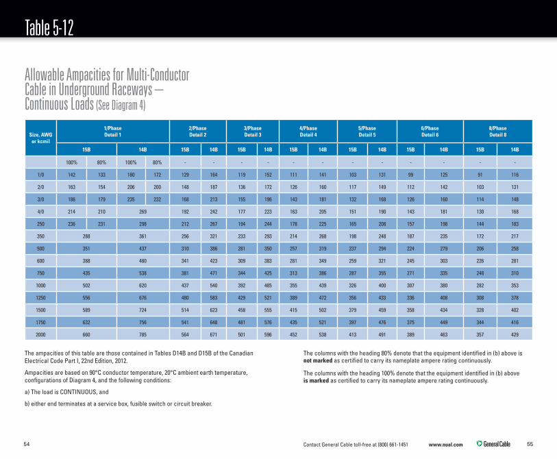
Table 5-12
Allowable Ampacities for Multi-Conductor Cable in Underground Raceways – Continuous Loads (See Diagram 4)
Size, AWGor kcmil
1/PhaseDetail 1
2/PhaseDetail 2
3/PhaseDetail 3
4/PhaseDetail 4
5/PhaseDetail 5
6/PhaseDetail 6
8/PhaseDetail 8
15B 14B 15B 14B 15B 14B 15B 14B 15B 14B 15B 14B 15B 14B
100% 80% 100% 80% - - - - - - - - - - - -
1/0 142 133 180 172 129 164 119 152 111 141 103 131 99 125 91 116
2/0 163 154 206 200 148 187 136 172 126 160 117 149 112 142 103 131
3/0 186 179 235 232 168 213 155 196 143 181 132 168 126 160 114 148
4/0 214 210 269 192 242 177 223 163 205 151 190 143 181 130 168
250 236 231 298 212 267 194 244 178 225 165 208 157 198 144 183
350 288 361 256 321 233 293 214 268 198 248 187 235 172 217
500 351 437 310 386 281 350 257 319 237 294 224 279 206 258
600 388 480 341 423 309 383 281 349 259 321 245 303 226 281
750 435 538 381 471 344 425 313 386 287 355 271 335 248 310
1000 502 620 437 540 392 485 355 439 326 400 307 380 282 353
1250 556 676 480 583 429 521 389 472 356 433 336 408 308 378
1500 589 724 514 623 458 555 415 502 379 459 358 434 328 402
1750 632 756 541 648 481 576 435 521 397 476 375 449 344 416
2000 660 785 564 671 501 596 452 538 413 491 389 463 357 429
The ampacities of this table are those contained in Tables D14B and D15B of the Canadian Electrical Code Part I, 22nd Edition, 2012.
Ampacities are based on 90°C conductor temperature, 20°C ambient earth temperature, configurations of Diagram 4, and the following conditions:
a) The load is CONTINUOUS, and
b) either end terminates at a service box, fusible switch or circuit breaker.
The columns with the heading 80% denote that the equipment identified in (b) above is not marked as certified to carry its nameplate ampere rating continuously.
The columns with the heading 100% denote that the equipment identified in (b) above is marked as certified to carry its nameplate ampere rating continuously.

Contact General Cable toll-free at (800) 661-1451 www.nual.com 5756
Notes and Corrections
Tables 5-5 to 5-12 Inclusive GeneralThe following notes and corrections are based on notes in Appendix B of the Canadian Electrical Code. Ampacities of underground installations based on conditions of use not as set out in the following notes should either be justified by precise calculation according to the method of paragraph 4-004(1)(d) or (2)(d) or derived in accordance with paragraph 4-004(1)(b) or (2)(b) of the Canadian Electrical Code. The ampacities shown in Tables 5-5 to 5-12 inclusive have been determined using the calculation in IEEE Standard 835, Standard Power Cable Ampacity Tables, for the cable arrangements shown in Diagrams 1 to 4 inclusive. It is recommended that ampacities for single-conductor cables directly buried in the earth be selected from Table 5-5 or 5-6 for installation configurations shown in Diagram 1, and those for cables
in separate underground raceways be selected from Table 5-7 or 5-8 for installation configurations shown in Diagram 2. It is recommended that ampacities for three-conductor cables directly buried in the earth be selected from Table 5-9 or 5-10 for installation configurations shown in Diagram 3, and those for cables in separate underground raceways be selected from Table 5-11 or 5-12 for installation configurations shown in Diagram 4.
Voltage DropThe allowable ampacities of Tables 5-5 to 5-12 inclusive are based on temperatures alone and do not take voltage drop into consideration. For voltage drop information, refer to rule 8-102.
Conductor TemperatureUnderground ampacities for conductor temperatures of 75°C and 60°C respectively may be obtained by multiplying the appropriate ampacity at 90°C conductor temperature from Tables 5-5 to 5-12 inclusive by
0.866 (for 75°C) or 0.756 (for 60°C). General Cable NUAL Brand conductors for underground use are all rated for 90°.
Ambient Earth TemperatureAmpacities for underground installations at ambient earth temperatures other than the assumed value of 20°C may be obtained by multiplying the appropriate underground ampacity obtained from Tables 5-5 to 5-12 by the factor: SQRT[(90-Tæ)/70] where Tæ is the new ambient earth temperature.
Stacked ArrangementsFor stacked arrangements of two single-conductors per phase in parallel (one row located vertically over another row), it is recommended that they be obtained from Detail 5 of Tables 5-5 and 5-6 for directly buried cables, or from Detail 2 of Tables 5-7 and 5-8 for cables in underground raceways.

Contact General Cable toll-free at (800) 661-1451 www.nual.com 5958
Notes and Corrections (continued)
Deratings Due to Sheath Circulating CurrentsFor single-conductor metal armoured and metal sheathed cables in which the sheath, armour, or bonding conductors are bonded at more than one point, the derating factors of Canadian Electrical Code Rule 4-010 apply, unless the ampacity has been determined by detailed calculation according to the method outlined in paragraphs (1)(e), (1)(f), (2)(e) or (2)(f) of Canadian Electrical Code Rule 4-004.
Recommendations for 3, 5 and 7 Single-Conductors/Phase in ParallelIt is recommended that ampacities for three single-conductors per phase in parallel, and for five single-conductors per phase in parallel, with spacings, directly buried in the earth, be selected from Table 5-5 or 5-6 for installation configurations shown in Diagram 1, Detail 5 and Detail 7, respectively. It is recommended that ampacities for three
single-conductors per phase in parallel installed in separate underground raceways be selected from Table 5-7 or 5-8 for installation configurations shown in Diagram 2, Detail 3 and Detail 4, respectively. It is recommended that ampacities for seven three-conductor cables in separate underground raceways be selected from Table 5-11 or 5-12, Detail 7.
Recommendations for Groups of Conductors in TwosIt is recommended that the ampacities of groups of conductors in twos and two-conductor cables, be obtained from ampacity Tables 5-9 to 5-12, inclusive, as for groups of three conductors, and three-conductor cables, respectively, for the appropriate spacings between groups and numbers of conductors in parallel. The neutral conductor of a single phase, three wire system need not be counted in the determination of ampacities.
Note: The concept of “Load Factor” was introduced into code ampacities for the first time in the 2002 Code. Load Factor is usually expressed as a percentage of the average load/rated load. Cyclical changes in demand on the cable during the day can lower expected temperature rise in insulated cables in the earth, and consequently some jurisdictions may permit smaller conductor sizes based on load factors less than 100%, when it can be shown or readily predicted that the load factor is justified. The application of load factors less than 100% can be found in the source reference for underground ampacities, IEEE Standard 835, Standard Power Cable Ampacity Tables.

Contact General Cable toll-free at (800) 661-1451 www.nual.com 6160
Application Rules
Section 4: Conductors4-004 Ampacity of Wires and Cables (see Appendices B and I)*(1) The maximum current that a copper conductor of a given size and insulation may carry shall be as follows:
(a) single-conductor and single-conductor metal-sheathed or armoured cable, in a free air run, with a cable spacing not less than 100% of the larger cable diameter, as specified in Table 1;
(b) one, two, or three conductors in a run of raceway, or 2- or 3-conductor cable, except as indicated in Subrule (1)(d), as specified in Table 2;
(c) four or more conductors in a run of raceway or cable, as specified in Table 2 with the correction factors applied as specified in Table 5C;
(d) single-conductor and 2-, 3-, and 4-conductor cables and single-conductor and 2-, 3-, and 4-conductor metal-armoured and metal-sheathed cables, in conductor sizes No. 1/0 AWG and
larger, installed in accordance with configurations described in Diagrams B4-1 to B4-4 in an underground run, directly buried or in a raceway, as specified in Tables D8A through D15B.
(e) underground configurations not specified in Item (d), in conductor sizes No. 1/0 AWG and larger, as calculated by the IEEE 835 calculation method; and
(f) underground configurations in conductor sizes smaller than No. 1/0 AWG, as specified in Item (b) or as calculated by the IEEE 835 calculation method.
(2) The maximum current that an aluminum conductor of a given size and insulation may carry shall be as follows:
(a) single-conductor and single-conductor metal-sheathed or armoured cable, in a free air run, with a cable spacing not less than 100% of the larger cable diameter, as specified in Table 3;
(b) one, two, or three conductors in a run of raceway, or 2- or 3-conductor cable, except as indicated in Subrule (2)(d), as specified in Table 4;
(c) four or more conductors in a run of raceway or cable, as specified in Table 4 with the correction factors applied as specified in Table 5C; and
(d) single-conductor and 2-, 3-, and 4-conductor cables and single-conductor and 2-, 3-, and 4-conductor metal-armoured and metal-sheathed cables, in conductor sizes No. 1/0 AWG and larger, in an underground run, directly buried or in a raceway, as calculated by the method of IEEE 835.
(3) A neutral conductor that carries only the unbalanced current from other conductors, as in the case of normally balanced circuits of three or more conductors, shall not be counted in determining ampacities as provided for in Subrules (1) and (2).
(4) When a load is connected between a single-phase conductor and the neutral, or between each of two phase conductors and the neutral, of a three-phase, 4-wire system, the common conductor carries a current comparable to that in
* Please reference the Canadian Electrical Code (CEC) Part 1, Appendices B and I

Contact General Cable toll-free at (800) 661-1451 www.nual.com 6362
Application Rules
the phase conductors and shall be counted in determining the ampacities as provided for in Subrules (1) and (2).
(5) The maximum allowable ampacity of neutral supported cable shall be as specified in Tables 36A and 36B.
(6) A bonding conductor shall not be counted in determining the ampacities as provided for in Subrules (1) and (2).
(7) The correction factors specified in this Rule (a) shall apply only to, and shall be determined from, the number of power and lighting conductors in a cable or raceway; and (b) shall not apply to conductors installed in auxiliary gutters.
(8) The ampacity correction factors of Table 5A shall apply where conductors are installed in an ambient temperature exceeding or anticipated to exceed 30°C.
(9) Where the free air spacing between adjacent single-conductor cables is maintained at not less than 25% nor more than 100% of the diameter of
the largest cable, the ampacity shall be obtained from Subrules (1)(a) and (2)(a) for copper and aluminum conductors respectively, multiplied by the correction factor obtained from Table 5D.
(10) Where up to and including four single-conductor cables in free air are spaced at less than 25% of the diameter of the largest conductor or cable, the ampacity shall be the same as that obtained from Subrules (1)(b) and (2)(b) for copper and aluminum conductors respectively, multiplied by the correction factor obtained from Table 5B.
(11) Notwithstanding Subrule (10), where not more than four non-jacketed single-conductor mineral-insulated cables are grouped together in conformance with Rule 4-010(3) and are installed on a messenger or as open runs with a maintained free air space of not less than 2.15 times the diameter of the largest cable contained within the group and adjacent groups or cables, the
ampacity of each conductor in the group shall be permitted to be determined in accordance with Subrule (1)(a) without applying the factors of Table 5B.
(12) More than four single-conductor cables in free air, when spaced at less than 25% of the largest cable diameter, shall have an ampacity obtained from Tables 2 and 4 for copper and aluminum conductors respectively, multiplied by the correction factor obtained from Table 5C.
(13) Notwithstanding Subrule (12), when the length of a multiple conductor cable run is less than 600 mm, the correction factor from Table 5C shall not apply.
(14) The ampacity of conductors of different temperature ratings installed in the same raceway shall be determined on the basis of the conductor having the lowest temperature rating.
(15) The ampacity of conductors added to a raceway and the ampacity of the conductors
already in the raceway shall be determined in accordance with the applicable Subrules.
(16) Where more than one ampacity could apply for a given circuit of single-conductor or multi-conductor cables as a consequence of a transition from an underground portion to a portion above ground, the lower value shall apply except as permitted in Subrule (17).
(17) Where the lower ampacity portion of a cable installation consisting of not more than four-conductors in total does not exceed 10% of the circuit length or 3 m, whichever is less, the higher ampacity shall be permitted.
(18) When the load factor of the load is less than 1.00 and is known or can be supported by documentation, the ampacity of conductors derived from Subrules (1)(d) and (2)(d) shall be permitted to be increased by application of that load factor in the calculation of the ampacity.
(19) In consideration of the increased ampacity of any

Contact General Cable toll-free at (800) 661-1451 www.nual.com 6564
Application Rules
conductor derived in accordance with Subrule (16), no further factors based on load diversity shall be permitted.
(20) The ampacity of nickel or nickel-clad conductors shall be calculated using the method described in IEEE 835.
(21) The maximum allowable ampacity of bare or covered conductors in free air shall be as specified in Table 66.
4-006 Temperature Limitations (see Appendix B)*(1) Where equipment is marked with a maximum conductor termination temperature, the maximum allowable ampacity of the conductor shall be based on the corresponding temperature column from Table 1, 2, 3 or 4.
(2) Where equipment is not marked with a maximum conductor termination temperature, 90˚C shall be used by default.
4-010 Induced Voltages and Currents in Metal Armour or Sheaths of Single-Conductor Cables (see Appendix B)*(1) Where sheath currents in single-conductor cables having continuous sheaths of lead, aluminum, stainless steel, or copper are likely to cause the insulation of the conductors to be subjected to temperatures in excess of the insulation ratings, the cables shall be
(a) derated to 70% of the current-carrying rating that would otherwise apply;
(b) derated in accordance with the manufacturer's recommendations and in compliance with Rule 2-030; or
(c) installed in a manner that prevents the flow of sheath currents.
(2) Circulating currents in single-conductor armoured cable shall be treated in the same manner as sheath currents in Subrule (1).
(3) Single-conductor cables carrying more than 200 A shall
not enter ferrous metal boxes through individual openings.
(4) Where single-conductor cables carrying more than 200 A enter ferrous metal boxes, precautions shall be taken to prevent overheating of the wall of the box by induction.
(5) Precautions to be taken to prevent overheating of the metal shall include the use of non-ferrous or non-metallic box connectors or cable glands, locknuts, bushings, and ground bushings.
(6) All cables making up a circuit shall enter the box through one common non-ferrous or insulating plate having a minimum thickness of 6.0 mm unless a deviation is allowed in accordance with Rule 2-030.
(7) Where single-conductor mineral-insulated cables are used, all current-carrying conductors shall be grouped together to minimize induced voltage on the sheath.
Section 8: Circuit Loading and Demand Factors8-100 Current CalculationsWhen calculating currents that will result from loads, expressed in watts or volt amperes, to be supplied by a low-voltage alternating-current system, the voltage divisors to be used shall be 120, 208, 240, 277, 347, 416, 480, or 600 as applicable.
8-102 Voltage Drop(1) Voltage drop in an installation shall
(a) be based upon the calculated demand load of the feeder or branch circuit;
(b) not exceed 5% from the supply side of the consumer's service (or equivalent) to the point of utilization; and
(c) not exceed 3% in a feeder or branch circuit.
(2) For the purposes of Subrule (1) the demand load on a branch circuit shall be the connected load, if known; otherwise it shall be 80% of the rating of the
* Please reference the Canadian Electrical Code (CEC) Part 1, Appendix B

Contact General Cable toll-free at (800) 661-1451 www.nual.com 6766
Application Rules
overload or overcurrent devices protecting the branch circuit, whichever is smaller.
8-104 Maximum Circuit Loading (see Appendix B)*(1) The ampere rating of a consumer's service, feeder, or branch circuit shall be the ampere rating of the overcurrent device protecting the circuit or the ampacity of the conductors, whichever is less.
(2) The calculated load in a circuit shall not exceed the ampere rating of the circuit.
(3) The calculated load in a consumer's service, feeder, or branch circuit shall be considered a continuous load unless it can be shown that in normal operation it will not persist for
(a) a total of more than 1 h in any two-hour period if the load does not exceed 225 A; or
(b) a total of more than 3 h in any six-hour period if the load exceeds 225 A.
(4) Where a fused switch or circuit breaker is marked
for continuous operation at 100% of the ampere rating of its overcurrent devices, the continuous load as determined from the calculated load shall not exceed
(a) 100% of the rating of the circuit where the ampacity of the conductors is based on Column 2, 3, or 4 of Table 2 or 4; or
(b) 85% of the rating of the circuit where the ampacity of the conductors is based on Column 2, 3, or 4 of Table 1 or 3.
(5) Where a fused switch or circuit breaker is marked for continuous operation at 80% of the ampere rating of its overcurrent devices, the continuous load as determined from the calculated load shall not exceed
(a) 80% of the rating of the circuit where the ampacity of the conductors is based on Column 2, 3, or 4 of Table 2 or 4; or
(b) 70% of the rating of the circuit where the ampacity of the conductors is based on Column 2, 3, or 4 of Table 1 or 3.
(6) If other derating factors are applied to reduce the conductor ampacity, the conductor size shall be the greater of that so determined or that determined by Subrule (4) or (5).
(7) Notwithstanding the requirements of Rule 4-004(1)(d) and (2)(d), the ampacity of the underground conductors shall not exceed in any case those determined by Subrules (4)(b) and (5)(b) of this rule.
8-106 Use of Demand Factors(1) The size of conductors and switches computed in accordance with this Section shall be the minimum used except that, if the next smaller standard size in common use has an ampacity not more than 5% less than this minimum, the smaller size conductor shall be permitted.
(2) In any case other than a service calculated in accordance with Rules 8-200 and 8-202, where the design of an installation is based on requirements in excess of those given in this Section, the service
and feeder capacities shall be increased accordingly.
(3) Where two or more loads are installed so that only one can be used at any one time, the one providing the greatest demand shall be used in determining the calculated demand.
(4) Where it is known that electric space-heating and air-conditioning loads are installed and will not be used simultaneously, whichever is the greater load shall be used in calculating the demand.
(5) Where a feeder supplies loads of a cyclic or similar nature such that the maximum connected load will not be supplied at the same time, the ampacity of the feeder conductors shall be permitted to be based on the maximum load that may be connected at any one time.
(6) The ampacity of conductors of feeders or branch circuits shall be in accordance with the Section(s) dealing with the respective equipment being supplied.
* Please reference the Canadian Electrical Code (CEC) Part 1, Appendix B

Contact General Cable toll-free at (800) 661-1451 www.nual.com 6968
Application Rules
(7) Notwithstanding the requirements of this Section, the ampacity of the conductors of a feeder or branch circuit need not exceed the ampacity of the conductors of the service or of the feeder from which they are supplied.
(8) Where additional loads are to be added to an existing service or feeder, the augmented load shall be permitted to be calculated by adding the sum of the additional loads, with demand factors as permitted by this Code to the maximum demand load of the existing installation as measured over the most recent 12-month period, but the new calculated load shall be subject to Rule 8-104(4) and (5).
Section 12: Conductors – Wiring Methods12-012 Underground Installations (see Appendix B)*(1) Direct buried conductors, cables, or raceways shall be installed to meet the minimum cover requirements of Table 53.
(2) The minimum cover requirements shall be permitted to be reduced by 150 mm where mechanical protection is placed in the trench over the underground installation.
(3) Mechanical protection shall consist of one of the following and, when in flat form, shall be wide enough to extend at least 50 mm beyond the conductor, cables, or raceways on each side
(a) treated planking at least 38 mm thick
(b) poured concrete at least 50 mm thick
(c) concrete slabs at least 50 mm thick
(d) concrete encasement at least 50 mm thick; or
(e) other suitable material.
(4) Direct buried conductors or cables shall be installed so that they run adjacent to each other and do not cross over each other and with a layer of screened sand with a maximum particle size of 4.75 mm or screened
earth at least 75 mm deep both above and below the conductors.
(5) Where conductors or cables rise for terminations or splices or where access is otherwise required, they shall be protected from mechanical damage by location or by rigid conduit terminated vertically in the trench and including a bushing or bell end fitting, or other acceptable protection, at the bottom end from 300 mm above the bottom of the trench to at least 2 m above finished grade, and beyond that as may be required by other Rules of the Code, and with sufficient slack provided in the conductors at the bottom end of the conduit so that the conductors enter the conduit from a vertical position.
(6) Where a deviation has been allowed in accordance with Rule 2-030, cables buried directly in earth shall be permitted to be spliced or tapped in trenches without the use of splice boxes, and such splices and taps shall be made by methods and with material approved for the purpose.
12-106 Multi- and Single-Conductor Cables(1) Where multi-conductor cable is used, all conductors of a circuit shall be contained in the same multi-conductor cable except that, where it is necessary to run conductors in parallel due to the capacity of an ac circuit, additional cables shall be permitted to be used, provided that any one such cable
(a) includes an equal number of conductors from each phase and the neutral; and
(b) shall be in accordance with Rule 12-108.
(2) A multi-conductor cable shall not contain circuits of different systems except as permitted in Rule 12-3030.
(3) Where single-conductor cables are used, all single-conductor cables of a circuit shall be of the same type and temperature rating and, if run in parallel, shall be in accordance with Rule 12-108.
(4) Single-conductor armoured cable used as a current-carrying
* Please reference the Canadian Electrical Code (CEC) Part 1, Appendix B

Contact General Cable toll-free at (800) 661-1451 www.nual.com 7170
Application Rules
conductor shall be of a type having non-magnetic armour.
(5) A single-conductor cable carrying a current over 200 A shall be run and supported in such a manner that the cable is not encircled by magnetic material.
12-108 Conductors in Parallel (see Appendix B)*(1) Ungrounded and grounded circuit conductors of similar conductivity in sizes No. 1/0 AWG and larger, copper or aluminum, shall be permitted to be installed in parallel sets provided that each parallel phase or grounded conductor set is individually comprised of conductors that are
(a) free of splices throughout the total length;
(b) the same circular mil area;
(c) the same type of insulation;
(d) terminated in the same manner;
(e) the same conductor material; and
(f) the same length.
(2) Notwithstanding Subrule (1)(a), a single splice per conductor shall be permitted
(b) to meet the requirements of Rule 4-006; and
(c) where spliced in the same manner.
(3) In parallel sets, conductors of one phase, polarity, or grounded circuit conductor shall not be required to have the same characteristics as those of another phase, polarity, or grounded circuit conductor.
(4) The orientation of single-conductor cables in parallel, with respect to each other and to those in other phases, shall be such as to minimize the difference in inductive reactance and the unequal division of current.
(5) Conductors of similar conductivity in sizes smaller than No. 1/0 AWG copper shall be permitted in parallel to supply control power to indicating instruments and devices, contactors, relays, solenoids, and similar control devices, provided that
(a) they are contained within one cable;
(b) the ampacity of each individual conductor is sufficient to carry the entire load current shared by the parallel conductors; and
(c) the overcurrent protection is such that the ampacity of each individual conductor will not be exceeded if one or more of the parallel conductors becomes inadvertently disconnected.
(6) Where parallel conductors include grounded circuit conductors, each parallel set shall have a separate grounded circuit conductor.
(7) Where the size of neutral conductors is reduced in conformance with Rule 4-024, neutral conductors smaller than No. 1/0 AWG shall be permitted in circuits run in parallel, provided that they are installed in conformance with the requirements of Subrule (1)(a), (b), (c), (d), and (e).
12-118 Termination and Splicing of Aluminum Conductors(1) Adequate precaution shall be given to the termination and splicing of aluminum conductors, including the removal of insulation and separators, the cleaning (wire brushing) of stranded conductors, and the compatibility and installation of fittings.
(2) A joint compound, capable of penetrating the oxide film and preventing its reforming, shall be used for terminating or splicing all sizes of stranded aluminum conductors, unless the termination or splice is approved for use without compound and is so marked.
(3) Equipment connected to aluminum conductors shall be specifically approved for the purpose and be so marked, except
(a) where the equipment has only leads for connection to the supply; and
(b) equipment such as outlet boxes having only grounding terminals.* Please reference the Canadian Electrical Code
(CEC) Part 1, Appendix B
Contact General Cable toll-free at (800) 661-1451 www.nual.com 7372
Application Rules
(4) Aluminum conductors shall not be terminated or spliced in wet locations unless the termination or splice is adequately protected against corrosion.
(5) Field-assembled connections between aluminum lugs and aluminum or copper busbars or lugs, involving bolts or studs 9.5 mm diameter or larger, shall include as part of the joint any of the following means of allowing for expansion of the parts:
(a) a conical spring washer;
(b) a helical spring washer of the heavy series, provided that a flat steel washer of thickness not less than one-sixth of the nominal diameter of the bolt or stud is interposed between the helical washer and any aluminum surface against which it would bear; or
(c) aluminum bolts or studs, provided that all the elements in the assembled connection are of aluminum.
(6) Connection of aluminum conductors to wiring devices
having wire-binding terminal screws, around which conductors can be looped under the head of the screw, shall be made by forming the conductor in a clockwise direction around the screw into three-fourths of a complete loop, and only one conductor shall be connected to any one screw.
Armoured Cable12-600 Armoured Cable Work RulesRules 12-602 to 12-618 apply only to armoured cable work.
12-602 Use (see Appendix B)*(1) Armoured cable shall be permitted to be installed in or on buildings or portions of buildings of either combustible or non-combustible construction.
(2) Armoured cable shall be of the type listed in Table 19 as suitable for direct burial if used
(a) for underground runs;
(b) for circuits in masonry or concrete, provided that the cable is encased or embedded in at least 50 mm of the masonry or concrete; or
(c) in locations where it will be exposed to weather, continuous moisture, excessive humidity, or to oil or other substances having a deteriorating effect on the insulation.
(3) Notwithstanding Subrule (2), armoured cable in which the armouring is made wholly or in part of aluminum shall not be embedded in concrete containing reinforcing steel, unless
(a) the concrete is known to contain no chloride additives; or
(b) the armour has been treated with a bituminous base of paint or other means to prevent galvanic corrosion of the aluminum.
(4) Where armoured cables are laid in or under cinders or cinder concrete, they shall be protected from corrosive action by a grouting of non-cinder concrete at least 25 mm thick entirely surrounding them unless they are 450 mm or more under the cinders or cinder concrete.
(5) In buildings of non-combustible construction,
armoured cables having conductors not larger than No. 10 AWG copper or aluminum shall be permitted to be laid on the face of the masonry or other material of which the walls and ceiling are constructed and shall be permitted to be buried in the plaster finish for extensions from existing outlets only.
(6) Armoured cable with overall jacket shall be permitted for use in a raceway when it is installed in accordance with Rule 12-902(2).
12-604 Protection for Armoured Cables in LanesIf subject to mechanical injury and unless otherwise protected, steel guards of not less than No. 10 MSG, adequately secured, shall be installed to protect armoured cables less than 2 m above grade in lanes and driveways.
12-606 Use of Thermoplastic-Covered Armoured CableArmoured cable of the type listed in Table 19 as suitable for direct earth burial and having * Please reference the Canadian Electrical Code
(CEC) Part 1, Appendix B

Contact General Cable toll-free at (800) 661-1451 www.nual.com 7574
Application Rules
a thermoplastic outer covering shall be used only where the outer covering will not be subjected to mechanical injury.
12-608 Continuity of Armoured CableArmoured cable shall be run in a manner such that the mechanical and electrical continuity of the armour is maintained throughout the run, and the armour of cables shall be mechanically and electrically secured to all equipment to which it is attached.
12-610 Terminating Armoured Cable(1) Where conductors issue from armour, they shall be protected from abrasion by bushings of insulating material or equivalent devices.
(2) Where conductors are No. 8 AWG or larger, copper or aluminum, such protection shall consist of
(a) insulated-type bushings, unless the equipment is equipped with a hub having a smoothly rounded throat; or
(b) insulating material fastened securely in place that will separate the conductors from the armoured cable fittings and afford adequate resistance to mechanical injury.
(3) Where armoured cable is fastened to equipment, the connector or clamp shall be of such design as to leave the insulating bushing or its equivalent visible for inspection.
(4) Where conductors connected to open wiring issue from the ends of armouring, they shall be protected with boxes or with fittings having a separately bushed hole for each conductor.
12-612 Proximity to Knob-and-Tube and Non-Metallic-Sheathed Cable SystemsWhere armoured cable is used in a building in which concealed knob-and-tube wiring or concealed non-metallic-sheathed cable wiring is installed, the cable shall not be fished if there is a possibility of damage to the existing wiring.
12-614 Radii of Bends in Armoured Cables(1) Where armoured cables are bent during installation, the radius of the curve of the inner edge of the bends shall be at least 6 times the external diameter of the armoured cable.
(2) Bends shall be made without undue distortion of the armour and without injury to its inner or outer surfaces.
12-616 Concealed Armoured Cable Installation(1) Where armoured cable is run through studs, joists, or other members, it shall be
(a) located so that its outer circumference is at least 32 mm from the nearest edge of the members; or
(b) protected from mechanical injury where it passes through the holes in the members.
(2) Where armoured cable is installed immediately behind baseboards, it shall be protected from mechanical injury from driven nails.
12-618 Running of Cable Between Boxes, etc.Armoured cable shall be supported between boxes and fittings in accordance with Rule 12-510.
Cable Trays12-2200 Method of Installation (see Appendix B)*(1) Cable trays shall be installed as a complete system using fittings or other means to provide adequate cable support and bending radius before the conductors are installed.
(2) The maximum design load and associated support spacing shall not exceed the load/span ratings of the cable tray.
(3) Cable trays shall not pass through walls except where the walls are constructed of non-combustible material.
(4) Cable trays shall be permitted to extend vertically through floors in dry locations, if provided with fire stops in accordance with Rule 2-124, and if totally enclosed where passing through
* Please reference the Canadian Electrical Code (CEC) Part 1, Appendix B

Contact General Cable toll-free at (800) 661-1451 www.nual.com 7776
Application Rules
and for a minimum distance of 2 m above the floor to provide adequate protection from mechanical injury.
(5) Cable trays shall be adequately supported by non-combustible supports.
(6) The minimum clearances for cable trays shall be
(a) 150 mm vertical clearance, excluding depth of cable trays, between cable trays installed in tiers except that, where cables of 50 mm diameter or greater may be installed, the clearance shall be 300 mm;
(b) 300 mm vertical clearance from the top of the cable tray to all ceilings, heating ducts, and heating equipment and 150 mm for short length obstructions;
(c) 600 mm horizontal clearance on one side of cable trays mounted adjacent to one another or to walls or other obstructions, where the width of the cable tray installation does not exceed 1 m; and
(d) 600 mm horizontal clearance on each side of cable trays mounted adjacent to one
another, where the width of the cable tray installation exceeds 1 m.
(7) At least one expansion joint shall be installed in any cable tray run where the expansion of the cable tray due to the maximum probable temperature change during and after installation can damage the cable tray.
12-2202 Conductors in Cable Trays (see Appendix B)*(1) Conductors for use in cable trays shall be as listed in Table 19 and, except as permitted in Subrules (2) and (3), shall have a continuous metal sheath or interlocking armour.
(2) Type TC tray cable shall be permitted in cable trays in areas of industrial establishments that are inaccessible to the public, provided that the cable is
(a) installed in conduit, other suitable raceway, or direct buried, when not in cable tray;
(b) provided with mechanical protection where subject to damage either during or after installation;
(c) no smaller than No. 1/0 AWG if a single-conductor is used; and
(d) installed only where qualified persons service the installation.
(3) Conductors having moisture-resistant insulation and flame-tested non-metal coverings or sheaths of a type listed in Table 19 shall be permitted in ventilated or non-ventilated cable trays where not subject to damage during or after installation in
(a) electrical equipment vaults and service rooms; and
(b) other locations that are inaccessible to the public and are constructed as a service room where a deviation has been allowed in accordance with Rule 2-030.
(4) Single-conductors shall be fastened to prevent excessive movement due to fault-current magnetic forces.
(5) Where single-conductors are fastened to cable trays, precautions shall be taken to prevent overheating of the fasteners due to induction.
12-2204 Joints and Splices within Cable TraysWhere joints and splices are made on feeders or branch circuits within cable trays, the connectors shall be insulated and shall be accessible.
12-2206 Connection to Other Wiring MethodsWhere cable trays are connected to other wiring methods, the arrangement shall be such that the conductors will not be subject to mechanical damage or abrasion, and such that effective bonding will be maintained.
12-2208 Provisions for Bonding(1) Where metal supports for metal cable trays are bolted to the tray and are in good electrical contact with the grounded structural metal frame of a building, the tray shall be deemed to be bonded to ground.
(2) Where the conditions of Subrule (1) do not apply, the metal cable tray shall be adequately bonded at intervals
* Please reference the Canadian Electrical Code (CEC) Part 1, Appendix B

Contact General Cable toll-free at (800) 661-1451 www.nual.com 7978
Application Rules
not exceeding 15 m and the size of bonding conductors shall be based on the ampacity of the largest ungrounded conductor as specified in Rule 10-814 in the circuits carried by the cable tray.
12-2210 Ampacities of Conductors in Cable Trays(1) In ventilated and ladder-type cable trays, where the air space between adjacent conductors, cables, or both is maintained at greater than 100% of the diameter of the larger conductor or cable, the ampacity of the conductors or cables shall be the value specified in Item (a) or (b):
(a) single-conductors, single-conductor metal-sheathed or armoured cable, and single-conductor mineral-insulated cable, as specified in Tables 1 and 3; and
(b) multi-conductor cables as specified in Tables 2 and 4, multiplied by the correction factor in Table 5C for the number of conductors in each cable.
(2) In ventilated and ladder-type cable trays, where the air space
between adjacent conductors, cables, or both is maintained at not less than 25% nor more than 100% of the diameter of the larger conductor or cable, the ampacity of the conductors or cables shall be the value specified in Subrule (1), multiplied by the correction factor specified in Table 5D for the arrangement and number of conductors or cables involved, unless a deviation has been allowed in accordance with Rule 2-030 for other correction factors.
(3) In ventilated and ladder-type cable trays, where the air space between adjacent conductors, cables, or both is less than 25% of the diameter of the larger conductor or cable, and for any spacing in a non-ventilated cable tray, the ampacity of the conductors or cables shall be the value as specified in Table 2 or 4 multiplied by the correction factor specified in Table 5C for the total number of conductors in the cable tray.
(4) In determining the total number of conductors in the
cable tray in Subrule (3), Rule 4-004(7) shall apply.
(5) Where cable trays are located in room temperatures above 30°C, the temperature correction factor of Table 5A shall be applied to the ampacities determined from Subrules (1), (2), and (3) as applicable.

Contact General Cable toll-free at (800) 661-1451 www.nual.com 8180
Tables
RW90 600V Maximum Permissible Number of Conductors in Conduit †
AWG or KCMILAmpacities Nominal Diameter of Conduit
Table 3 Table 4 1/2” 3/4” 1” 1-1/4” 1-1/2” 2” 2-1/2” 3” 3-1/2” 4”
8 60 45 2 5 8 14 19 32 46 72 96 124
6 85 55** 1 3 6 11 14 24 35 54 72 93
4 115 75 1 2 4 8 11 18 25 39 53 68
3 130 85 1 1 3 6 9 15 21 33 44 57
2 150 100 1 1 3 5 7 12 18 28 38 49
1 175 115 1 1 1 4 5 9 14 21 28 37
1/0 205 135 1 1 3 4 8 11 18 24 31
2/0 235 150 1 1 3 4 6 9 15 20 26
3/0 270 175 1 1 2 3 5 8 12 17 22
4/0 315 205 1 1 1 2 4 6 10 14 18
250 355 230 1 1 1 3 5 8 11 14
300 395 260 1 1 1 3 4 7 10 12
350 445 280 1 1 1 2 4 6 8 11
400 480 305 1 1 2 3 5 7 10
500 545 350 1 1 1 3 4 6 8
600 615 385 1 1 1 1 3 5 6
750 700 435 1 1 1 3 4 5
1000 845 500 1 1 1 3 4
1500 1070 585 1 1 1 1
NUAL Brand Conductor Ampacities in Air and Maximum Permissible Number of Conductors in Conduit
† For 3-wire 120/240 V and 120/208 V service conductors for single dwellings, or for feeder conductors supplying single dwelling units of row housing of apartment and similar buildings, and sized in accordance with Rules 8-200(1), 8-200(2), and 8-202(1), the allowable ampacity for No. 6 AWG shall be 60 A. In this case, the 5% adjustment of Rule 8-106(1) cannot be applied.

Contact General Cable toll-free at (800) 661-1451 www.nual.com 8382
Tables
RW90 600V Maximum Permissible Number of Conductors in Conduit †
AWG or KCMILAmpacities Nominal Diameter of Conduit
Table 1 Table 2 1/2” 3/4” 1” 1-1/4” 1-1/2” 2” 2-1/2” 3” 3-1/2” 4”
14 35 25 9 16 25 45 61 101 144 200 200 200
12 40 30 7 12 20 35 48 79 113 175 200 200
10 55 40 5 9 15 27 37 61 87 134 179 200
8 80 55 2 4 7 13 18 30 43 67 90 116
6 105 75 1 3 5 10 13 23 32 50 67 87
4 140 95 1 2 4 7 10 16 23 36 49 63
3 165 115 1 1 3 6 8 14 20 31 41 53
2 190 130 1 1 3 5 7 11 17 26 35 45
1 220 145 1 1 1 3 5 8 12 19 25 33
1/0 260 170 1 1 3 4 7 10 16 22 28
2/0 300 195†† 1 1 2 3 6 8 13 18 23
3/0 350 225 1 1 1 3 5 7 11 15 19
4/0 405 260 1 1 2 4 6 9 12 16
250 455 290 1 1 1 3 5 7 10 13
300 500 320 1 1 1 3 4 6 8 11
350 570 350 1 1 2 3 5 7 10
400 615 380 1 1 1 3 5 7 9
500 700 430 1 1 1 2 4 5 7
600 780 475 1 1 1 3 4 6
750 885 535 1 1 2 3 4
1000 1055 615 1 1 1 3 3
† For 3-wire 120/240 V and 120/208 V service conductors for single dwellings, or for feeder conductors supplying single dwelling units of row housing of apartment and similar buildings, and sized in accordance with Rules 8-200(1), 8-200(2), and 8-202(1), the allowable ampacity for sizes No. 6 and No. 2/0 AWG shall be 60 A and 200 A, respectively. In this case, the 5% adjustment of Rule 8-106(1) cannot be applied.
Copper Conductor Ampacities in Air and Maximum Permissible Number of Conductors in Conduit

Contact General Cable toll-free at (800) 661-1451 www.nual.com 8584
Tables
AmbientTemp.
C°
Correction Factor
60° 75° 90° 105° 110° 125° 150° 200° 250°
35 0.91 0.94 0.96 0.97 0.97 0.97 0.98 0.99 0.99
40 0.82 0.88 0.91 0.93 0.94 0.95 0.96 0.97 0.98
45 0.71 0.82 0.87 0.89 0.9 0.92 0.94 0.95 0.97
50 0.58 0.75 0.82 0.86 0.87 0.89 0.91 0.94 0.95
55 0.41 0.67 0.76 0.82 0.83 0.86 0.89 0.92 0.94
60 — 0.58 0.71 0.77 0.79 0.83 0.87 0.91 0.93
65 — 0.47 0.65 0.73 0.75 0.79 0.84 0.89 0.92
70 — 0.33 0.58 0.68 0.71 0.76 0.82 0.87 0.9
75 — — 0.5 0.63 0.66 0.73 0.79 0.86 0.89
80 — — 0.41 0.58 0.61 0.69 0.76 0.84 0.88
90 — — — 0.45 0.5 0.61 0.71 0.8 0.85
100 — — — 0.26 0.35 0.51 0.65 0.77 0.83
110 — — — — — 0.4 0.58 0.73 0.8
120 — — — — — 0.23 0.5 0.69 0.77
130 — — — — — — 0.41 0.64 0.74
140 — — — — — — 0.29 0.59 0.71
Table 5A – Correction Factors Applying to Tables 1, 2, 3, & 4 (Ampacity Correction Factors for Ambient Temperatures Above 30°C) (See Rules 4-004(8) and 12-2210 and Tables 1 To 4, 57, And 58)

Contact General Cable toll-free at (800) 661-1451 www.nual.com 8786
Tables
Table 5B – Correction Factors for Tables 1 & 3 (Where from 2 to 4 Single-Conductors are Present and in Contact) (See Rules 4-004(9) and Tables 1, 3 and D3)
Table 5C – Ampacity Correction Factors for Tables 2 & 4 (See Rule 4-004 and Tables 2 and 4)
Table 5D – Current Rating Correction Factors Where Spacings are Maintained (Ventilated and Ladder-Type Cable Trays) (See Rule 12-2210)
Table 8 – Maximum Allowable Percent Conduit and Tubing Fill (See Rule 12-1014 & 38-032)
Number of Conductors Correction Factors
2 0.90
3 0.85
4 0.80
Number of Conductors Ampacity Correction Factors
1-3 1.00
4-6 0.80
7-24 0.70
25-42 0.60
43 & up 0.50
Number of Conductors or Cables Horizontally
1 2 3 4 5 6
Vertically (Layers)1 1.00 0.93 0.87 0.84 0.83 0.82
2 0.89 0.83 0.79 0.76 0.75 0.74
Notes:1) Where four conductors form a three-phase-with-neutral system, the values for three
conductors may be used. Where three conductors form a single-phase, three-wire system, the values for two conductors may be used.
2) Where more than four conductors are in contact, the ratings for conductors in raceways shall be used.
Construction
Number of Conductors or Multi-conductor Cables
1 2 3 4 Over 4
Conductors or multi-conductor cables (not lead-sheathed)
53 31 40 40 40
Lead-sheathed conductors or multi-conductor cables
55 30 40 38 35

Contact General Cable toll-free at (800) 661-1451 www.nual.com 8988
Tables
Normal Conduit Size
Internal Diameter (mm)
Cross-sectional Area of Conduit and Tubing (mm2)
100% 55% 53% 40% 38% 35% 31% 30%
16 (1/2) 15.8 107.8 4.13 103.9 78.41 74.49 68.61 60.77 58.81
21 (3/4) 20.9 189.2 4.6 182.3 137.6 130.7 120.4 106.7 103.2
27 (1) 26.6 306.7 5.23 295.5 223 211.9 195.2 172.9 167.3
35 (1-1/4) 35.1 530.7 5.99 511.4 386 366.7 337.7 299.1 289.5
41 (1-1/2) 40.9 722.4 7.71 696.1 525.4 499.1 459.7 407.2 394
53 (2) 52.5 1191 8.93 1147 866 822.7 757.7 671.1 649.5
63 (2-1/2) 62.7 1699 9.64 1637 1236 1174 1081 957.5 926.7
78 (3) 79.9 2623 10.46 2528 1908 1812 1669 1479 1431
91 (3-1/2) 90.1 3508 12.49 3381 2551 2424 2233 1977 1914
103 (4) 102.3 4517 13.51 4353 3285 3121 2875 2546 2464
116 (4-1/2) 114.5 5659 14.68 5453 4115 3910 3601 3189 3086
129 (5) 128.2 7099 16 6841 5163 4905 4517 4001 3872
155 (6) 154.1 10 251 17.47 9879 7456 7083 6524 5778 5592
Table 9 – Cross-Sectional Areas of Conduit and Tubing (See Rule 12-1014)
Note:The dimensions shown are typical of metallic conduit and tubing. Other figures more accurately representing the actual dimensions of a particular product may be substituted, when known. Dimensions of other circular raceways may be obtained from the approved standard to which they are manufactured.
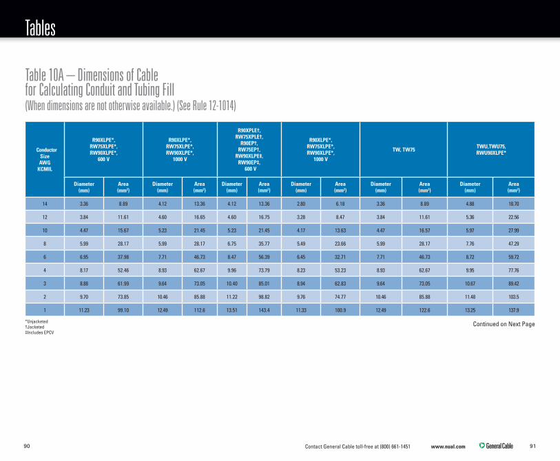
Contact General Cable toll-free at (800) 661-1451 www.nual.com 9190
Tables
ConductorSizeAWG
KCMIL
R90XLPE*,RW75XLPE*,RW90XLPE*,
600 V
R90XLPE*,RW75XLPE*,RW90XLPE*,
1000 V
R90XPLE†, RW75XPLE†,
R90EP†, RW75EP†,
RW90XLPE‡, RW90EP‡,
600 V
R90XLPE*,RW75XLPE*,RW90XLPE*,
1000 V
TW, TW75 TWU,TWU75,RWU90XLPE*
Diameter(mm)
Area(mm2)
Diameter(mm)
Area(mm2)
Diameter(mm)
Area(mm2)
Diameter(mm)
Area(mm2)
Diameter(mm)
Area(mm2)
Diameter(mm)
Area(mm2)
14 3.36 8.89 4.12 13.36 4.12 13.36 2.80 6.18 3.36 8.89 4.88 18.70
12 3.84 11.61 4.60 16.65 4.60 16.75 3.28 8.47 3.84 11.61 5.36 22.56
10 4.47 15.67 5.23 21.45 5.23 21.45 4.17 13.63 4.47 16.57 5.97 27.99
8 5.99 28.17 5.99 28.17 6.75 35.77 5.49 23.66 5.99 28.17 7.76 47.29
6 6.95 37.98 7.71 46.73 8.47 56.39 6.45 32.71 7.71 46.73 8.72 59.72
4 8.17 52.46 8.93 62.67 9.96 73.79 8.23 53.23 8.93 62.67 9.95 77.76
3 8.88 61.99 9.64 73.05 10.40 85.01 8.94 62.83 9.64 73.05 10.67 89.42
2 9.70 73.85 10.46 85.88 11.22 98.82 9.76 74.77 10.46 85.88 11.48 103.5
1 11.23 99.10 12.49 112.6 13.51 143.4 11.33 100.9 12.49 122.6 13.25 137.9
Table 10A – Dimensions of Cable for Calculating Conduit and Tubing Fill (When dimensions are not otherwise available.) (See Rule 12-1014)
Continued on Next Page*Unjacketed†Jacketed‡Includes EPCV

Contact General Cable toll-free at (800) 661-1451 www.nual.com 9392
Tables
ConductorSizeAWG
KCMIL
R90XLPE*,RW75XLPE*,RW90XLPE*,
600 V
R90XLPE*,RW75XLPE*,RW90XLPE*,
1000 V
R90XPLE†, RW75XPLE†,
R90EP, RW75EP†,
RW90XLPE‡, RW90EP,
600 V
R90XLPE*,RW75XLPE*,RW90XLPE*,
1000 V
TW, TW75 TWU,TWU75,RWU90XLPE*
Diameter(mm)
Area(mm2)
Diameter(mm)
Area(mm2)
Diameter(mm)
Area(mm2)
Diameter(mm)
Area(mm2)
Diameter(mm)
Area(mm2)
Diameter(mm)
Area(mm2)
1/0 12.27 118.3 13.53 143.9 14.55 166.4 12.37 120.3 13.53 143.9 14.28 160.2
2/0 13.44 141.9 14.70 169.8 15.72 194.2 13.54 144.0 14.70 169.8 15.45 187.5
3/0 14.74 170.6 16.00 201.0 17.02 227.5 14.84 172.9 16.00 201.0 16.76 220.6
4/0 16.21 206.4 17.47 239.7 18.49 268.5 16.31 209.0 17.47 239.7 18.28 262.4
250 17.90 251.8 19.17 288.5 21.21 353.2 18.04 255.7 19.43 296.4 20.20 320.5
300 19.30 292.6 20.56 332.1 22.60 401.2 19.44 296 9.20.82 340.5 21.54 364.4
350 20.53 331.0 21.79 372.9 23.83 446.0 20.67 335.6 22.05 381.9 22.81 408.6
400 21.79 373.0 23.05 417.3 25.09 494.5 21.93 337.8 23.31 426.8 24.07 455.0
450 22.91 412.2 24.17 458.8 26.21 539.5 23.05 417.3 24.43 468.7 25.19 498.4
500 23.95 450.5 25.21 499.2 27.25 583.2 24.09 455.8 25.47 509.5 26.24 540.8
600 26.74 561.7 27.24 582.9 30.04 708.8 — — 28.26 627.3 29.02 661.4
700 28.55 640.0 29.05 662.6 31.85 796.5 — — 30.07 710.0 30.82 746.0
750 29.41 679.3 29.91 702.6 32.71 840.3 — — 30.93 751.3 31.69 788.7
800 30.25 718.7 30.75 742.6 33.55 884.0 — — 31.77 792.7 32.53 831.1
900 31.85 796.6 32.35 821.8 35.15 970.2 — — 33.37 874.5 34.13 914.9
1000 32.32 872.0 33.82 898.4 36.62 1053 — — 34.84 953.4 35.60 995.4
1250 37.56 1108 38.32 1153 42.38 1411 — — 39.08 1200 39.08 1199
1500 40.68 1300 41.44 1349 45.50 1626 — — 42.20 1399 42.96 1449
1750 43.58 1492 44.34 1544 48.40 1840 — — 45.10 1598 45.86 1652
2000 46.27 1681 47.03 1737 51.09 2050 — — 47.79 1794 48.55 1851
Table 10A Continued (See Rule 12-1014)
*Unjacketed†Jacketed‡Includes EPCV
Note:Dimensions for aluminum conductors are subjected to the range of sizes to which they are certified. Data is for compressed stranded conductors.

Contact General Cable toll-free at (800) 661-1451 www.nual.com 9594
Tables
Conductor size
AWG or kcmil
RPV*, 600 V RPV*, 1000 V RPV*, 2000 V RPV†, 600 V RPV†, 1000 V RPV†, 2000 VRPVU*, 1000 V
2000 VRPVU†, 1000 V
2000 V
Dia.,mm
Area,mm2
Dia.,mm
Area,mm2
Dia.,mm
Area,mm2
Dia.,mm
Area,mm2
Dia.,mm
Area,mm2
Dia.,mm
Area,mm2
Dia.,mm
Area,mm2
Dia.,mm
Area,mm2
14 3.37 8.92 4.13 13.4 4.89 18.78 4.13 13.4 4.89 18.78 5.65 25.07 4.89 18.78 5.65 25.07
12 3.84 11.58 4.6 16.62 5.36 22.56 4.6 16.62 5.36 22.56 6.12 29.42 5.36 22.56 6.12 29.42
10 4.47 15.69 5.23 21.48 5.99 28.18 5.23 21.48 5.99 28.18 7.51 44.3 5.99 28.18 6.75 35.78
8 5.99 28.18 5.99 28.18 7.27 41.51 7.51 44.3 7.51 44.3 8.79 60.68 7.77 47.42 9.29t 67.78
6 6.95 37.94 7.71 46.69 8.23 53.2 8.47 56.35 9.23 66.91 9.75 74.66 8.73 59.86 10.25 82.52
4 8.17 52.42 8.93 62.63 9.45 70.14 9.69 73.75 10.45 85.77 10.97 94.52 9.95 77.76 11.47 103.3
3 8.88 61.93 9.64 72.99 10.16 81.07 10.4 84.95 11.16 97.82 11.68 107.1 10.66 89.25 12.18 116.5
2 9.7 73.9 10.46 85.93 10.98 94.69 11.22 98.87 11.98 112.7 13.26 138.1 11.48 103.5 13.76 148.7
1 11.23 99.05 12.49 122.5 13.01 132.9 13.51 143.4 14.77 171.3 15.29 183.6 13.25 137.9 15.53 189.4
1/0 12.25 117.9 13.51 143.4 14.03 154.6 14.53 165.8 15.79 195.8 16.31 208.9 14.27 159.9 16.55 215.1
2/0 13.42 141.4 14.68 169.3 15.2 181.5 15.7 193.6 16.96 225.9 17.48 240 15.44 187.2 17.72 246.6
3/0 14.74 170.6 16 201.1 16.52 214.3 17.02 227.5 18.28 262.4 18.8 277.6 16.76 220.6 19.04 284.7
4/0 16.21 206.4 17.47 239.7 17.99 254.2 18.49 268.5 19.75 306.4 21.29 356 18.23 261 21.53 364.1
250 17.9 251.6 19.16 288.3 19.94 312.3 21.2 353 22.46 396.2 23.24 424.2 20.18 319.8 23.48 433
300 19.3 292.6 20.56 332 21.34 357.7 22.6 401.1 23.86 447.1 24.64 476.8 21.58 365.8 24.88 486.2
Table 10B – Dimensions of Photovoltaic Cable for Calculating Conduit and Tubing Fill (See Rule 12-1014)
*Unjacketed†Jacketed

Contact General Cable toll-free at (800) 661-1451 www.nual.com 9796
Tables
Conductor size
AWG or kcmil
RPV*, 600 V RPV*, 1000 V RPV*, 2000 V RPV†, 600 V RPV†, 1000 V RPV†, 2000 V RPVU*, 1000 V 2000 V RPVU†, 1000 V 2000 V
Dia.,mm
Area,mm2
Dia.,mm
Area,mm2
Dia.,mm
Area,mm2
Dia.,mm
Area,mm2
Dia.,mm
Area,mm2
Dia.,mm
Area,mm2
Dia.,mm
Area,mm2
Dia.,mm
Area,mm2
350 20.6 333.3 21.86 375.3 22.64 402.6 23.9 448.6 25.16 497.2 25.94 528.5 22.88 411.2 26.18 538.3
400 21.79 372.9 23.05 417.3 23.83 446 25.09 494.4 26.35 545.3 27.13 578.1 24.07 455 27.37 588.4
450 22.91 412.2 24.17 458.8 24.95 488.9 26.21 539.5 27.47 592.7 28.25 626.8 25.19 498.4 28.49 637.5
500 23.95 450.5 25.21 499.2 25.99 530.5 27.25 583.2 28.51 638.4 29.29 673.8 26.23 540.4 29.53 684.9
600 26.74 561.6 27.24 582.8 28.78 650.5 30.04 708.7 30.54 732.5 32.08 808.3 29.04 662.3 32.34 821.4
700 28.55 640.2 29.05 662.8 30.59 734.9 31.85 796.7 32.35 821.9 33.89 902.1 30.85 747.5 34.15 915.9
750 29.41 679.3 29.91 702.6 31.45 776.8 32.71 840.3 33.21 866.2 34.75 948.4 31.71 789.7 35.01 962.7
800 30.22 717.3 30.72 741.2 32.26 817.4 33.52 882.5 34.02 909 35.56 993.1 32.52 830.6 35.82 1008
900 31.85 796.7 32.35 821.9 33.89 902.1 35.15 970.4 35.65 998.2 37.19 1086 34.15 915.9 37.45 1102
1000 33.32 872 33.82 898.3 35.36 982 36.62 1053 37.12 1082 38.66 1174 35.62 996.5 38.92 1190
1250 37.56 1108 38.32 1153 39.86 1248 42.38 1411 43.14 1462 44.68 1568 39.86 1248 44.68 1568
1500 40.68 1300 41.44 1349 42.98 1451 45.5 1626 46.26 1681 47.8 1795 42.98 1451 47.8 1795
1750 43.58 1492 44.34 1544 45.88 1653 48.4 1840 49.16 1898 50.7 2019 45.88 1653 50.7 2019
2000 46.27 1681 47.03 1737 48.57 1853 51.09 2050 51.85 2111 53.39 2239 48.57 1853 53.39 2239
Table 10B Continued (See Rule 12-1014)
Note:Aluminum conductors may not be available in the same range as copper conductors.
*Unjacketed†Jacketed

Contact General Cable toll-free at (800) 661-1451 www.nual.com 9998
Tables
Ampacity A, of largest ungrounded conductor in the circuit or equivalent for
multiple parallel conductors not exceeeding
Size of Bonding Conductor
Copper WireAWG
Aluminum WireAWG
20 14 12
30 12 10
40 10 8
60 10 8
100 8 6
200 6 4
300 4 2
400 3 1
500 2 0
600 1 00
800 0 000
1000 00 0000
1200 000 250 kcmil
1600 0000 350 kcmil
2000 250 kcmil 400 kcmil
2500 350 kcmil 500 kcmil
3000 400 kcmil 600 kcmil
4000 500 kcmil 800 kcmil
5000 700 kcmil 1000 kcmil
6000 800 kcmil 1250 kcmil
Ampacity of largest service conductor or equivalent
for multi-conductors not exceeeding – amperes
Size of Grounding Conductor
Copper Wire AWG
Metal Conduit or PipeElectrical
Metallic Tubing
(mm) (in) (mm) (in)
60 8 21 3/4 27 1
100 8 27 1 35 1 1/4
200 6 35 1 1/4 41 1 1/2
400 3 63 2 1/2 63 2 1/2
600 1 78 3 103 4
800 0 103 4 103 4
Over 800 00 155 6 – –
Conductor Size AWG & kcmil
Maximum Distance – Metres
Copper Aluminum
14 to 8 30 30
6 to 0 30 60
00 to 0000 24 55
250 to 350 18 40
Over 350 to 500 15 35
Over 500 to 750 12 30
Over 750 10 25
Table 16 – Minimum Size Conductors for Bonding Conductors (See Rules 10-204, 10-626, 10-814, 10-816, 10-906, 12-1814, 24-104, 24-202, 30-1030, 68-058 and 68-406)
Table 18 – Minimum Size of Grounding Conductor for Service Raceway and Service Equipment (See Rule 10-812)
Table 21 – Supporting of Conductors in Vertical Runs of Raceways (See Rule 12-120)
Note:1) The ampacity of the largest ungrounded conductor, or the equivalent if multiple conductors are used, shall be determined from the appropriate Table in the Code, taking into consideration the number of conductors in the raceway or cable and the type of insulation.
Note: For installation of armoured cables in vertical raceways please contact General Cable for assistance. See the General Cable Armoured Cable Canadian Catalogue for additional information.

Contact General Cable toll-free at (800) 661-1451 www.nual.com 101100
Tables
Dimensions of Stranded Aluminum Conductors
*Reduced minimum number of wires for compact strandings shown in parentheses.
Conductor Wires Nominal Conductor Diameter
Size AWG
Area
No.
Diameter Class “B” Standard Compressed Round Compact Round
Circ. Mils mm2 sq. in. mm in. mm in mm in mm in
8 16510 8.37 .01297 7(6)* 1.23 .0486 3.71 .146 3.60 .142 3.40 .134
6 26240 13.30 .02061 7(6)* 1.55 .0612 4.67 .184 4.53 .178 4.29 .169
4 41740 21.15 .03278 7(6)* 1.96 .0772 5.89 .232 5.71 .225 5.41 .213
3 52620 26.66 .04133 7(6)* 2.30 .0867 6.60 .260 6.40 .252 6.05 .238
2 66360 33.62 .05212 7(6)* 2.47 .0974 7.42 .292 7.20 .283 6.81 .268
1 83690 42.41 .06573 19(7)* 1.69 .0664 8.43 .332 8.18 .322 7.59 .299
0/1 105600 53.51 .08291 19(7)* 1.89 .0745 9.47 .373 9.19 .362 8.53 .336
2/0 133100 67.44 .1045 19(11)* 2.13 .0837 10.64 .418 10.32 .406 9.55 .376
3/0 167800 85.02 .1318 19(15)* 2.39 .0940 11.94 .470 11.58 .456 10.7 .423
4/0 211600 107.22 .1662 19(17)* 2.68 .1055 13.41 .528 13.00 .512 12.1 .475
250 kcmil 126.68 .1963 37(18)* 2.09 .0822 14.60 .575 14.16 .558 13.2 .520
300 152.01 .2356 37(18)* 2.31 .0900 16.00 .630 15.52 .611 14.5 .570
350 177.34 .2749 37(24)* 2.47 .0973 17.30 .681 16.78 .661 15.6 .6161
400 202.68 .3142 37(24)* 2.64 .1040 18.49 .728 17.94 .706 16.7 .659
500 253.36 .3927 37(30)* 2.95 .1162 20.65 .813 20.03 .789 18.7 .736
600 304.02 .4712 61(34)* 2.52 .0992 22.68 .893 22.00 .866 20.7 .813
750 380.03 .5980 61(53)* 2.82 .1109 25.35 .998 24.59 .968 23.1 .908
1000 506.70 .7854 61(53)* 3.25 .1280 29.26 1.152 23.38 1.117 26.9 1.060
1250 633.38 .9817 90 2.98 .1172 32.47 1.289 31.76 1.250 — —
1500 760.05 1.178 90 3.26 .1284 35.86 1.412 34.78 1.370 — —
1750 886.70 1.374 127 2.98 .1174 38.76 1.526 37.60 1.479 — —
2000 1013.40 1.571 127 3.19 .1255 41.45 1.632 40.21 1.583 — —

Contact General Cable toll-free at (800) 661-1451 www.nual.com 103102
Tables
mm2
ASTM B800* /ASTM B801¹ ASTM B8¹ CSA 22.2 no. 38¹ CSA 22.2 no.38¹
APPROXIMATE NET WEIGHT AVERAGE DC RESISTANCE¹ 20°C
Aluminum Copper Aluminum Bare Copper
AWG or kcmil lbs/1000ft kg/km lbs/1000ft kg/km Ohms /km Ohms /Kft Ohms/km Ohms /K
0.519 *20 AWG – – 3.154 4.694 – – 33.8 10.3
0.519 *18 – – 5.015 7.464 – – 21.46 6.54
0.823 *16 – – 7.974 11.868 – – 13.45 4.1
2.08 *14 3.795 5.648 12.68 18.87 – – 8.46 2.58
3.31 *12 6.03 8.974 20.16 30 8.88 2.71 5.35 1.63
5.26 *10 9.501 14.27 32.06 47.72 5.59 1.7 3.35 1.02
8.37 8 15.5 29.1 50.97 75.86 3.52 1.07 2.1 0.64
13.3 6 24.7 36.8 81.05 120.63 2.21 0.674 1.32 0.403
21.2 4 39.3 58.5 128.9 191.8 1.39 0.424 0.83 0.253
26.7 3 49.5 73.7 162.5 241.9 1.1 0.336 0.659 0.201
33.6 2 62.5 93 204.9 304.9 0.875 0.267 0.522 0.159
42.4 1 78.8 117 258.4 384.6 0.693 0.211 0.413 0.126
53.5 1/0 99.4 148 325.8 484.9 0.55 0.168 0.328 0.1
67.4 2/0 126 186 410.9 611.5 0.436 0.133 0.261 0.0795
DC Resistance Values and Weights of Stranded Copper and Aluminum Conductors
* Solid conductors
¹ Reference standard used
* Approximate weights and average DC resistances are considered to apply to all types of strands. Conductor data and metric equivalents in these tables are based where possible on CSA Standard 22.2 No. 38
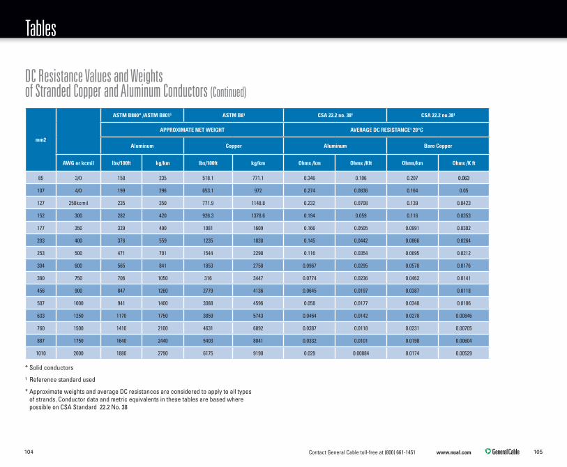
Contact General Cable toll-free at (800) 661-1451 www.nual.com 105104
Tables
mm2
ASTM B800* /ASTM B801¹ ASTM B8¹ CSA 22.2 no. 38¹ CSA 22.2 no.38¹
APPROXIMATE NET WEIGHT AVERAGE DC RESISTANCE¹ 20°C
Aluminum Copper Aluminum Bare Copper
AWG or kcmil lbs/100ft kg/km lbs/100ft kg/km Ohms /km Ohms /Kft Ohms/km Ohms /K ft
85 3/0 158 235 518.1 771.1 0.346 0.106 0.207 0.063
107 4/0 199 296 653.1 972 0.274 0.0836 0.164 0.05
127 250kcmil 235 350 771.9 1148.8 0.232 0.0708 0.139 0.0423
152 300 282 420 926.3 1378.6 0.194 0.059 0.116 0.0353
177 350 329 490 1081 1609 0.166 0.0505 0.0991 0.0302
203 400 376 559 1235 1838 0.145 0.0442 0.0866 0.0264
253 500 471 701 1544 2298 0.116 0.0354 0.0695 0.0212
304 600 565 841 1853 2758 0.0967 0.0295 0.0578 0.0176
380 750 706 1050 316 3447 0.0774 0.0236 0.0462 0.0141
456 900 847 1260 2779 4136 0.0645 0.0197 0.0387 0.0118
507 1000 941 1400 3088 4596 0.058 0.0177 0.0348 0.0106
633 1250 1170 1750 3859 5743 0.0464 0.0142 0.0278 0.00846
760 1500 1410 2100 4631 6892 0.0387 0.0118 0.0231 0.00705
887 1750 1640 2440 5403 8041 0.0332 0.0101 0.0198 0.00604
1010 2000 1880 2790 6175 9190 0.029 0.00884 0.0174 0.00529
DC Resistance Values and Weights of Stranded Copper and Aluminum Conductors (Continued)
* Solid conductors
¹ Reference standard used
* Approximate weights and average DC resistances are considered to apply to all types of strands. Conductor data and metric equivalents in these tables are based where possible on CSA Standard 22.2 No. 38

Contact General Cable toll-free at (800) 661-1451 www.nual.com 107106
TablesTables
Type of connection Wire size, AWG or kcmil Tightening torque, N•m
Wire-binding screws 14-10 1.4
Connectors withslotted screws (slot width —
1.2 mm or less and slotlength — 6.4 mm or less)
30-10 2.3
8 2.8
6-4 4.0
3 4.0
2 4.0
Connectors with slottedscrews (slot width over1.2 mm and slot length
over 6.4 mm)
30–10 4
8 4.5
6–4 5.1
3 5.6
2 5.6
1 5.6
1/0–2/0 5.6
3/0–4/0 5.6
250–350 5.6
400 5.6
500 5.6
600–750 5.6
800–1000 5.6
Type of connection Wire size, AWG or kcmil Tightening torque, N•m
Connectors for hexagonalhead — External drive wrench
(split-bolt connectors)
30–10 9
8 9
6–4 18.6
3 31.1
2 31.1
1 31.1
1/0–2/0 43.5
3/0–4/0 56.5
250–350 73.4
400 93.2
500 93.2
600–750 113
800–1000 124.3
1250–2000 124.3
* For proper termination of conductors, it is very important that field connections be properly tightened. In the absence of manufacturer’s instructions on the equipment, the torque values given in Tables D6 and D7 are recommended.
Because it is normal for some relaxation to occur in service, checking torque values some time after installation is not a reliable means of determining the values of torque applied at installation.
Note: The values in this table are correlated for consistency with the harmonized Standard CAN/CSA-C22.2 No. 65.
Table D6 – Recommended* Tightening Torques for Wire-binding Screws, Connectors with Slotted Screws, and Connectors for External Drive Wrenches (See Table D7)

Contact General Cable toll-free at (800) 661-1451 www.nual.com 109108
Tables
Type of connection Wire size, AWG or kcmil Tightening torque, N•m
Connectors for hexagonalhead — External drive wrench
(other connectors)
30–10 8.5
8 8.5
6–4 12.4
3 16.9
2 16.9
1 16.9
1/0–2/0 20.3
3/0–4/0 28.2
250–350 36.7
400 36.7
500 42.4
600–750 42.4
800–1000 56.5
1250–2000 67.8
Table D6 – Recommended* Tightening Torques for Wire-binding Screws, Connectors with Slotted Screws, and Connectors for External Drive Wrenches (Continued) (See Table D7)
* For proper termination of conductors, it is very important that field connections be properly tightened. In the absence of manufacturer’s instructions on the equipment, the torque values given in Tables D6 and D7 are recommended.
Because it is normal for some relaxation to occur in service, checking torque values some time after installation is not a reliable means of determining the values of torque applied at installation.
Note: The values in this table are correlated for consistency with the harmonized Standard CAN/CSA-C22.2 No. 65.
Usage Connection type and size Tightening torque, N•m
Socket (across flats) mm (inches)
Screws with recessed allen or square drives
3.2 (1/8) 5.1
4 (5/32) 11.3
4.8 (3/16) 13.6
5.6 (7/32) 16.9
6.4 (1/4) 22.6
7.9 (5/16) 31.1
9.5 (3/8) 42.4
12.7 (1/2) 56.5
14.3 (9/16) 67.8
Connecting hardware
Screw or bolt metric (SAE)
No. 8 or smaller 2
No. 10 3
M6 (1/4) 8
5/16 15
M10 (3/8) 26
5/16 41
M12 (1/2) 54
9/16, 5/8, or larger 75
Table D7 – Recommended Tightening Torques
(See Table D6)

Contact General Cable toll-free at (800) 661-1451 www.nual.com 111110
Tables
Usage Connection type and size Tightening torque, N•m
Slotted head screws smaller than No. 10 intended for use with No. 8 AWG or smaller
conductors
“Slot width of screw less than 1.2 mm (3/64 inch) — Slot length
mm (inches)”
< 4 (< 5/32) 7
4 (5/32) 7
4.8 (3/16) 7
5.6 (7/32) 7
6.4 (1/4) 9
Slot width of screw 1.2 mm (3/64 inch) and larger — Slot length
mm (inches)
< 4 (< 5/32) 9
4 (5/32) 12
4.8 (3/16) 12
5.6 (7/32) 12
6.4 (1/4) 12
7.1 (9/32) 15
> 7.1 (> (9/32) 20
* For proper termination of conductors, it is very important that field connections be properly tightened. In the absence of manufacturer’s instructions on the equipment, the torque values given in Tables D6 and D7 are recommended.
Because it is normal for some relaxation to occur in service, checking torque values some time after installation is not a reliable means of determining the values of torque applied at installation.
Note: The values in this table are correlated for consistency with the harmonized Standard CAN/CSA-C22.2 No. 65.
Metric conductor size, mm2Closest AWG or kcmil size(s) for selection of insulation and jacket thickness requirement
2.5 14
4 12
6 10
10 8
16 6
25 4
35 2
50 1/0
70 2/0
95 3/0
120 250
150 300
240 500
300 600
400 800
500 1000
630 1250
800 1500
1000 2000
Closest AWG or kcmil Size(s) to Metric Conductor Size(s)Table D7 – Recommended* Tightening Torques (Continued) (See Table D6)

Contact General Cable toll-free at (800) 661-1451 www.nual.com 113112
Basic Metric Conversion Factors Notes
Convert Into Multiply By
circular mils square mils 0.7854
cubic inches litres 0.01639
feet metres 0.3048
inches centimetres 2.540
kcmil square millimetres 0.5067
kilograms pounds 2.205
kilograms per kilometre pounds per foot 0.00067197
kilometres miles 0.6214
kilometres yards 1 094
metres feet 3.281
metres yards 1.094
millimeters inches 0.03937
pounds kilograms 0.4536
pounds per foot kilograms per kilometre 1488.16
square inches circular mils 1273.23
square inches square millimetres 645.16
square millimetres circular mils 1973.55
square millimetres square inches 1.550 x 10⁻³
tons (long) kilograms 1016
tons (long) pounds 2240
tons (metric) pounds 2205
tons (short) kilograms 907.18
tons (short) pounds 2000
Temperature
˚C = (˚F -32) x 5/9
˚F = (˚C x 9/5) + 32

Contact General Cable toll-free at (800) 661-1451 www.nual.com 115114
Notes

Contact General Cable toll-free at (800) 661-1451 www.nual.com 117116
Notes

Contact General Cable toll-free at (800) 661-1451 www.nual.com 119118
Notes

156 Parkshore Drive, Brampton, Ontario, Canada, L6T 5M1GENERAL CABLE and NUAL BRAND are trademarks of General Cable Technologies Corporation. ©2013. General Cable Technologies Corporation. Highland Heights, KY 41076 All rights reserved.Printed in USA
Phone: 1.800.561.06491.905.494.5300
Fax: 1.800.565.2529www.nual.com
Form number: BWC-0096E-1213