

Installer manual - NIBE · Sacrificial anode ... stalled in the anode from the factory and only...
24
Installer manual LEK VPB/VPBS Hot water heater IHB GB 1035-4 031441
Transcript of Installer manual - NIBE · Sacrificial anode ... stalled in the anode from the factory and only...

Installer manual
LEK
VPB/VPBSHot water heater
IHB GB 1035-4031441


Table of Contents1 Important information 2
Safety information 2
2 Delivery and handling 5Transport 5
Assembly 5
Supplied components 5
Removing the covers 5
3 The water heater design 6
4 Pipe connections 8General 8
Dimensions and pipe connections 8
Heat pump 10
Sun 10
Cold and hot water 10
Installation alternative 11
5 Electrical installation 12Sensors 12
Direct-current anode 13
6 Commissioning and adjusting 14Filling and venting 14
Start-up and inspection 15
7 Service 16Service actions 16
8 Technical data 17Dimensions and setting-out coordinates 17
Technical specifications 18
Item register 20
1Table of Contents |VPB/VPBS

Safety informationThis manual describes installation and service proceduresfor implementation by specialists.
This appliance is not intended for use by persons (includ-ing children) with reduced physical, sensory or mentalcapabilities, or lack of experience and knowledge, unlessthey have been given supervision or instruction concern-ing use of the appliance by a person responsible for theirsafety.Children should be supervised to ensure that they do notplay with the appliance.Rights to make any design or technical modifications arereserved.©NIBE 2010.
Symbols
NOTE
This symbol indicates danger to machine orperson.
Caution
This symbol indicates important informationabout what you should observe when maintain-ing your installation.
TIP
This symbol indicates tips on how to facilitateusing the product.
Marking
VPB 200 E is CE marked and fulfils IP21.
The CE marking means that NIBE ensures that the productmeets all regulations that are placed on it based on relev-ant EU directives. The CE mark is obligatory for mostproducts sold in the EU, regardless where they are made.
IP21 means that the product can be touched by hand,that objects with a diameter larger than or equivalent to12.5 mm cannot penetrate and cause damage and thatthe product is protected against vertically falling drops.
Serial number
The serial number can be found at the bottom right ofthe front cover.
Caution
Always give the product's serial number whenreporting a fault.
Country specific information
Installer manual
This installer manual must be left with the customer.
VPB/VPBSChapter 1 | Important information2
1 Important information
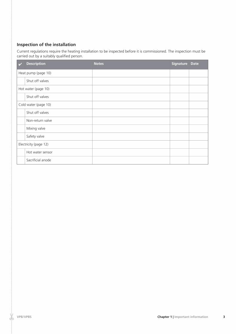
Inspection of the installation
Current regulations require the heating installation to be inspected before it is commissioned. The inspection must becarried out by a suitably qualified person.
DateSignatureNotesDescription✔
Heat pump (page 10)
Shut off valves
Hot water (page 10)
Shut off valves
Cold water (page 10)
Shut off valves
Non-return valve
Mixing valve
Safety valve
Electricity (page 12)
Hot water sensor
Sacrificial anode
3Chapter 1 | Important informationVPB/VPBS
......
......
......
......
......
......
......
......
......
......
......
......
......
......
......
......
......
......
......
......
......
......
......
......
......
......
......
......
......
......
......
......
......
......
......
......
......
......
......
......
......
......
......
......
......
......
......
......
......
......
......
......
......
......
......
......
......
......
......
......
......
......
......
.

Contact informationKNV Energietechnik GmbH, Gahberggasse 11, 4861 SchörflingAT
Tel: +43 (0)7662 8963-0 Fax: +43 (0)7662 8963-44 E-mail: [email protected] www.knv.atNIBE Wärmetechnik AG, Winterthurerstrasse 710, CH-8247 FlurlingenCH
Tel: (52) 647 00 30 Fax: (52) 647 00 31 E-mail: [email protected] www.nibe.chDruzstevni zavody Drazice s.r.o, Drazice 69, CZ - 294 71 Benatky nad JizerouCZ
Tel: +420 326 373 801 Fax: +420 326 373 803 E-mail: [email protected] www.nibe.czNIBE Systemtechnik GmbH, Am Reiherpfahl 3, 29223 CelleDE
Tel: 05141/7546-0 Fax: 05141/7546-99 E-mail: [email protected] www.nibe.deVølund Varmeteknik A/S, Member of the Nibe Group, Brogårdsvej 7, 6920 VidebækDK
Tel: 97 17 20 33 Fax: 97 17 29 33 E-mail: [email protected] www.volundvt.dkNIBE – Haato OY, Valimotie 27, 01510 VantaaFI
Puh: 09-274 697 0 Fax: 09-274 697 40 E-mail: [email protected] www.nibe.fiNIBE Energy Systems Ltd, 3C Broom Business Park, Bridge Way, Chesterfield S41 9QGGB
Tel: 0845 095 1200 Fax: 0845 095 1201 E-mail: [email protected] www.nibe.co.ukNIBE Energietechniek B.V., Postbus 2, NL-4797 ZG WILLEMSTAD (NB)NL
Tel: 0168 477722 Fax: 0168 476998 E-mail: [email protected] www.nibenl.nlABK AS, Brobekkveien 80, 0582 Oslo, Postadresse: Postboks 64 Vollebekk, 0516 OsloNO
Tel. sentralbord: +47 02320 E-mail: [email protected] www.nibeenergysystems.noNIBE-BIAWAR Sp. z o. o. Aleja Jana Pawła II 57, 15-703 BIAŁYSTOKPL
Tel: 085 662 84 90 Fax: 085 662 84 14 E-mail: [email protected] www.biawar.com.pl© "EVAN" 17, per. Boynovskiy, Nizhny NovgorodRU
Tel./fax +7 831 419 57 06 E-mail: [email protected] www.nibe-evan.ruNIBE AB Sweden, Box 14, Järnvägsgatan 40, SE-285 21 MarkarydSE
Tel: +46-(0)433-73 000 Fax: +46-(0)433-73 190 E-mail: [email protected] www.nibe.se
For countries not mention in this list, please contact NibeSweden or check www.nibe.eu for more information.
VPB/VPBSChapter 1 | Important information4

TransportVPB/VPBS should be transported and stored vertically ina dry place. The VPB/VPBS may, however, be carefullylaid on its back when being moved into a building.
R
0
R0
AssemblyThe water heater is only designed for upright installa-tion.
Position the water heater on a firm base that can bearits weight, preferably on a concrete floor or founda-tion. Use the water heater’s adjustable feet to obtaina horizontal and stable set-up.
The area where VPB/VPBS is located must be equippedwith floor drainage.
Supplied componentsVPB/VPBS Enamel
Potentiostat
Location
The kit of supplied items is placed on top of the product.
Removing the coversFront cover
1
2
LE
K
LE
K
1. Remove the screws from the lower edge of the frontcover.
2. Lift the cover out at the bottom edge and up.
Side covers
LE
K
LE
K
LE
K
The side covers can be removed to facilitate the installa-tion.
1. Remove the screws from the upper and lower edges.
2. Twist the cover slightly outward.
3. Move the cover backwards and slightly to the side.
4. Pull the cover to one side.
5. Pull the cover forwards.
5Chapter 2 | Delivery and handlingVPB/VPBS
2 Delivery and handling

LEKLEK
VPB/VPBSChapter 3 | The water heater design6
3 The water heater design
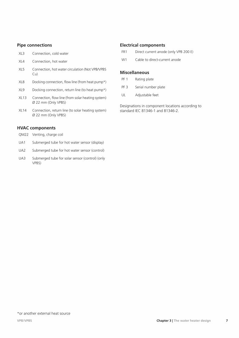
Pipe connections
Connection, cold waterXL3
Connection, hot waterXL4
Connection, hot water circulation (Not VPB/VPBSCu)
XL5
Docking connection, flow line (from heat pump*)XL8
Docking connection, return line (to heat pump*)XL9
Connection, flow line (from solar heating system)Ø 22 mm (Only VPBS)
XL13
Connection, return line (to solar heating system)Ø 22 mm (Only VPBS)
XL14
HVAC componentsVenting, charge coilQM22
Submerged tube for hot water sensor (display)UA1
Submerged tube for hot water sensor (control)UA2
Submerged tube for solar sensor (control) (onlyVPBS)
UA3
Electrical componentsDirect current anode (only VPB 200 E)FR1
Cable to direct-current anodeW1
MiscellaneousRating platePF 1
Serial number platePF 3
Adjustable feetUL
Designations in component locations according tostandard IEC 81346-1 and 81346-2.
*or another external heat source
7Chapter 3 | The water heater designVPB/VPBS

GeneralPipe installation must be carried out in accordance withcurrent norms and directives.
Internal support bushes should be fitted when a plasticpipe or annealed copper pipe is used. The water heatermust be fitted with the requisite valves, such as a safetyvalve, shut-off valve, non-return valve, and vacuum valve.An overflow pipe must be routed from the safety valveto a suitable drain. The size of the overflow pipe must bethe same as on the safety valve. Route the overflow pipefrom the safety valve enclosed along its entire length andensure that it is frost proof. The outlet of the overflowpipe should be visible and clearly away from any electricalcomponents.
Dimensions and pipe connec-tions
VPB 200/VPB 300
VPBS 300
Connection
22mmXL3 Cold water Ø
22mmXL4 Hot water Ø
15mmXL5* Hot water circulation Ø
22mmXL8 Docking connection, flow line Ø
22mmXL9 Docking connection, return lineØ
22mmXL13 Solar flow line Ø
22mmXL14 Solar return line Ø
*Not VPB Cu
VPB/VPBSChapter 4 | Pipe connections8
4 Pipe connections

80
100
600
600
30
60
205
135
535
480
25
390
25
80
9Chapter 4 | Pipe connectionsVPB/VPBS
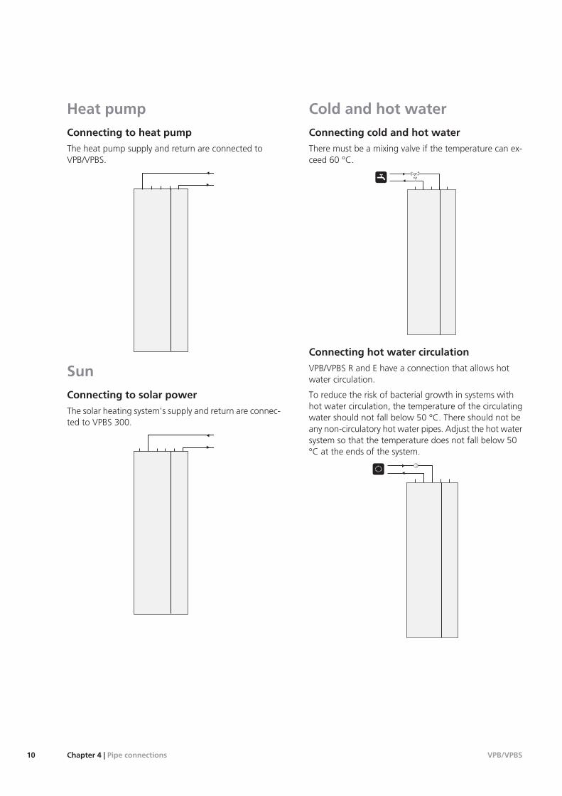
Heat pumpConnecting to heat pump
The heat pump supply and return are connected toVPB/VPBS.
SunConnecting to solar power
The solar heating system's supply and return are connec-ted to VPBS 300.
Cold and hot waterConnecting cold and hot water
There must be a mixing valve if the temperature can ex-ceed 60 °C.
Connecting hot water circulation
VPB/VPBS R and E have a connection that allows hotwater circulation.
To reduce the risk of bacterial growth in systems withhot water circulation, the temperature of the circulatingwater should not fall below 50 °C. There should not beany non-circulatory hot water pipes. Adjust the hot watersystem so that the temperature does not fall below 50°C at the ends of the system.
VPB/VPBSChapter 4 | Pipe connections10
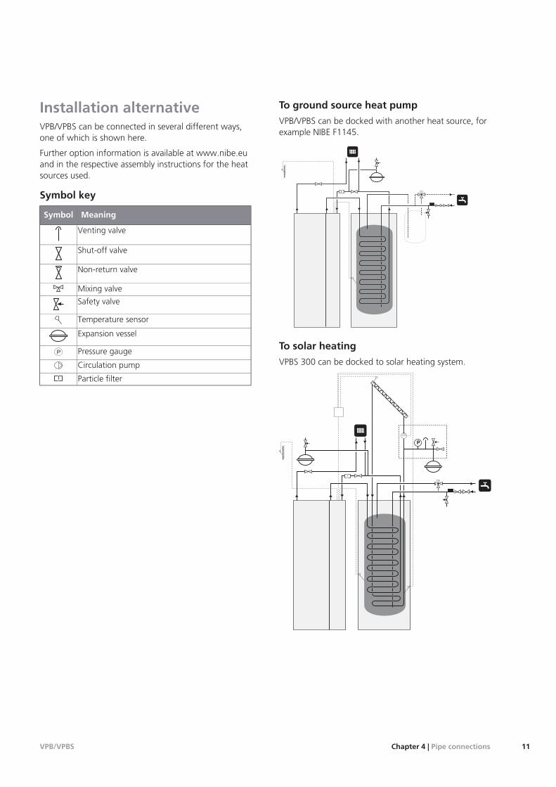
Installation alternativeVPB/VPBS can be connected in several different ways,one of which is shown here.
Further option information is available at www.nibe.euand in the respective assembly instructions for the heatsources used.
Symbol key
MeaningSymbol
Venting valve
Shut-off valve
Non-return valve
Mixing valve
Safety valve
Temperature sensor
Expansion vessel
Pressure gaugeP
Circulation pump
Particle filter
To ground source heat pump
VPB/VPBS can be docked with another heat source, forexample NIBE F1145.
T
To solar heating
VPBS 300 can be docked to solar heating system.
T
P
11Chapter 4 | Pipe connectionsVPB/VPBS
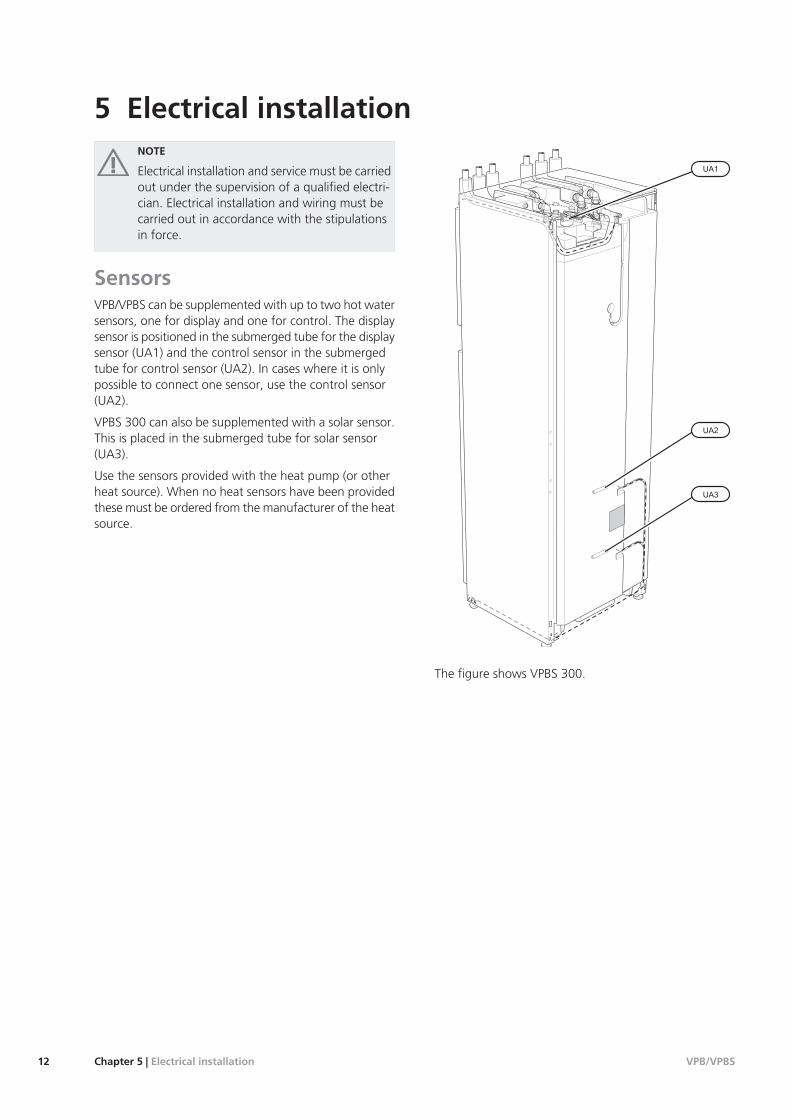
NOTE
Electrical installation and service must be carriedout under the supervision of a qualified electri-cian. Electrical installation and wiring must becarried out in accordance with the stipulationsin force.
SensorsVPB/VPBS can be supplemented with up to two hot watersensors, one for display and one for control. The displaysensor is positioned in the submerged tube for the displaysensor (UA1) and the control sensor in the submergedtube for control sensor (UA2). In cases where it is onlypossible to connect one sensor, use the control sensor(UA2).
VPBS 300 can also be supplemented with a solar sensor.This is placed in the submerged tube for solar sensor(UA3).
Use the sensors provided with the heat pump (or otherheat source). When no heat sensors have been providedthese must be ordered from the manufacturer of the heatsource.
LEK
The figure shows VPBS 300.
VPB/VPBSChapter 5 | Electrical installation12
5 Electrical installation

Direct-current anodeVPB 200E is factory equipped with direct-current anodeand supplied potentiostat. The anode cable (W1) is in-stalled in the anode from the factory and only needs tobe connected to the potentiostat.
1. Route the anode cable (W1) along the docking pipe,flow line (XL8).
2. Connect the anode cable (W1) to the potentiostat.
3. Connect the potensiostat to a suitable 230 V wallsocket.
NOTE
The cable between the potentiostat and theanode must either be extended or shortened.
The figure shows VPB 200 E.
13Chapter 5 | Electrical installationVPB/VPBS
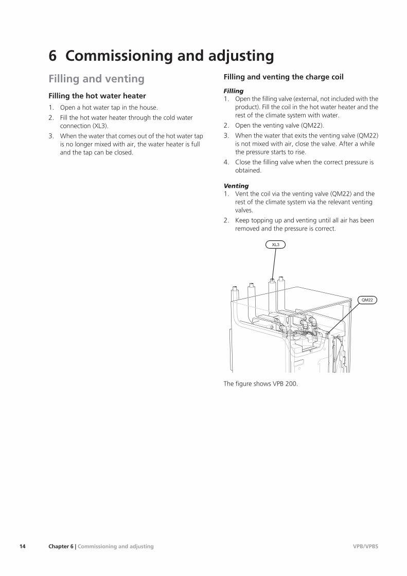
Filling and ventingFilling the hot water heater
1. Open a hot water tap in the house.
2. Fill the hot water heater through the cold waterconnection (XL3).
3. When the water that comes out of the hot water tapis no longer mixed with air, the water heater is fulland the tap can be closed.
Filling and venting the charge coil
Filling1. Open the filling valve (external, not included with the
product). Fill the coil in the hot water heater and therest of the climate system with water.
2. Open the venting valve (QM22).
3. When the water that exits the venting valve (QM22)is not mixed with air, close the valve. After a whilethe pressure starts to rise.
4. Close the filling valve when the correct pressure isobtained.
Venting1. Vent the coil via the venting valve (QM22) and the
rest of the climate system via the relevant ventingvalves.
2. Keep topping up and venting until all air has beenremoved and the pressure is correct.
The figure shows VPB 200.
VPB/VPBSChapter 6 | Commissioning and adjusting14
6 Commissioning and adjusting

Start-up and inspectionPressure drop diagram, charge coil
Docking connection, flow line (XL8) and docking connec-tion, return line (XL9).
VPB 200
ECu
0 0,05 0,1 0,15 0,2 0,25 0,3 0,35 0,4 0,45 0,5
5
0
10
15
20
25
30
40
35
45
50
Tryckfall(kPa)
Flöde (l/s)
R
VPB 300/VPBS 300
0
5
10
15
20
25
30
35
40
45
50
55
0 0,05 0,1 0,15 0,2 0,25 0,3 0,35 0,4 0,45 0,5
Tryckfall(kPa)
Cu
R
E
Pressure drop diagram, solar coil
Connection, flow line solar heating system (XL13) andconnection, return line solar heating system (XL14).
VPBS 300
0,02 0,04 0,06 0,08 0,1 0,12 0,14 0,16 0,18 0,2
Flöde (l/s)
0
10
20
30
40
50
60
70
0
E
Cu
15Chapter 6 | Commissioning and adjustingVPB/VPBS

Service actionsSafety valve
The water heater's safety valve sometimes releases a littlewater after hot water usage. This is because the coldwater, which enters the water heater to replace the hotwater, expands when heated causing the pressure to riseand the safety valve to open.
The function of the safety valve must be checked regu-larly. Perform checks as follows:
1. Open the valve by turning the knob anti-clockwisecarefully.
2. Check that water flows through the valve.
3. Close the valve by releasing it. If it does not closeautomatically when released, turn it anti-clockwiseslightly.
Emptying
The water heater is emptied through the siphon (withhose) in the cold water connection (XL3).
Drain the charge coil through the siphon (with hose) onthe docking connection, return to heat pump (XL9).
Drain the solar coil through the siphon (with hose) onthe connection, return to solar heating system (XL14).
VPB 200/VPB 300
VPBS 300
VPB/VPBSChapter 7 | Service16
7 Service

Dimensions and setting-out coordinates
80
100
80
25-50
1475
25-50
1775
600
600
30
60
205
135
535
480
25
390
25
17Chapter 8 | Technical dataVPB/VPBS
8 Technical data

Technical specificationsStainlessEnamelCopperVPB 200
176178172litreVolume
7.84.87.5litreVolume, charge coil
80111101kgNet weight
11.511.511.9kWHeat transfer (60/50 °C at 50 °C hot water temperature)
8.28.38.0kWhHeat content at 50°C
235238230litreEquivalent amount of hot water (40°C)
0.90.90.9hoursHeating time (10 °C to 45 °C) 8 kW charge power
1.81.81.8hoursHeating time (10 °C to 80 °C) 8 kW charge power
85°CMax operating temperature
3/0.3bar/MPaMax pressure, primary side
10/1.0bar/MPaMax pressure, water heater
12kWMax recommended heat pump size
088 518088 517088 515Part No.
StainlessEnamelCopperVPB 300
282274272litreVolume
8.88.48.5litreVolume, charge coil
101143130kgNet weight
13.113.714.8kWHeat transfer (60/50 °C at 50 °C hot water temperature)
13.412.712.6kWhHeat content at 50°C
376364362litreEquivalent amount of hot water (40°C)
1.41.41.4hoursHeating time (10 °C to 45 °C) 8 kW charge power
2.82.82.8hoursHeating time (10 °C to 80 °C) 8 kW charge power
85°CMax operating temperature
3/0.3bar/MPaMax pressure, primary side
10/1.0bar/MPaMax pressure, water heater
12kWMax recommended heat pump size
083 010083 011083 009Part No.
VPB/VPBSChapter 8 | Technical data18

EnamelCopperVPBS 300
268266litreVolume
8.48.5litreVolume, charge coil
4.04.4litreVolume, solar coil
150137kgNet weight
13.714.8kWHeat transfer (60/50 °C at 50 °C hot water temperature)
12.412.4kWhHeat content at 50°C
356354litreEquivalent amount of hot water (40°C)
1.41.4hoursHeating time (10 °C to 45 °C) 8 kW charge power
2.72.7hoursHeating time (10 °C to 80 °C) 8 kW charge power
85°CMax operating temperature
3/0.3bar/MPaMax pressure, primary side
10/1.0bar/MPaMax pressure, water heater
12kWMax recommended heat pump size
083 015083 012Part No.
19Chapter 8 | Technical dataVPB/VPBS

Item registerAAssembly, 5
CCold and hot water, 10Commissioning and adjusting, 14
Filling and venting, 14Pressure drop diagram, solar coil, 15Start-up and inspection, 15
Connecting cold and hot water, 10Connecting hot water circulation, 10Connecting to heat pump, 10Connecting to solar power, 10Contact information, 4
DDelivery and handling, 5
Assembly, 5Removing the covers, 5Supplied components, 5Transport, 5
Dimensions and pipe connections, 8Dimensions and setting-out coordinates, 17Direct-current anode, 13
EElectrical installation, 12
Direct-current anode, 13Sensors, 12
Emptying, 16
FFilling and venting, 14
Filling and venting the charge coil, 14Filling the hot water heater, 14
Filling and venting the charge coil, 14Filling the hot water heater, 14
HHeat pump, 10
Connecting hot water circulation, 10Connecting to heat pump, 10
IImportant information, 2
Safety information, 2Inspection of the installation, 3Installation alternative, 11
To ground source heat pump, 11
MMarking, 2
PPipe connections, 8
Cold and hot water, 10Connecting cold and hot water, 10Dimensions and pipe connections, 8General, 8Heat pump, 10Installation alternative, 11Sun, 10Symbol key, 11
Pressure drop diagram, charge coil, 15Pressure drop diagram, solar coil, 15
RRemoving the covers, 5
SSafety information, 2
Contact information, 4Inspection of the installation, 3Marking, 2Serial number, 2Symbols, 2
Safety valve, 16Sensors, 12Serial number, 2Service, 16
Service actions, 16Service actions, 16
Emptying, 16Safety valve, 16
Start-up and inspection, 15Pressure drop diagram, charge coil, 15
Sun, 10Connecting to solar power, 10
Supplied components, 5Symbol key, 11Symbols, 2
TTechnical data, 17
Dimensions and setting-out coordinates, 17Technical Data, 18
Technical Data, 18The water heater design, 6
List of components, 7Transport, 5
VPB/VPBSChapter 9 | Item register20
9 Item register


