Installation,Operation, and · PDF filecause personal injury and damage ... Model AF...
84
Installation, Operation, and Maintenance Manual Model AF (42"/1200mm/54"/60"/66") LM/LMR Bearings
Transcript of Installation,Operation, and · PDF filecause personal injury and damage ... Model AF...
Installation, Operation,and Maintenance ManualModel AF (42"/1200mm/54"/60"/66") LM/LMRBearings


Table of Contents
Table of ContentsIntroduction and Safety .......................................................................................................... 3
Introduction ............................................................................................................................. 3Safety ...................................................................................................................................... 3Safety terminology and symbols ............................................................................................. 3Environmental safety .............................................................................................................. 4Environmental safety .............................................................................................................. 5User safety .............................................................................................................................. 5Precautions before work ......................................................................................................... 6Precautions during work ......................................................................................................... 6Safety regulations for Ex-approved products in potentially explosive atmospheres ................ 6Product approval standards .................................................................................................... 7Product warranty ..................................................................................................................... 7
Transportation and Storage ................................................................................................... 9Inspect the delivery ................................................................................................................. 9
Inspect the package ............................................................................................................. 9Inspect the unit ..................................................................................................................... 9
Transportation guidelines ........................................................................................................ 9Pump handling ..................................................................................................................... 9Lifting the Pump / Sub-Base ................................................................................................. 9
Storage guidelines .................................................................................................................. 9Pump storage requirements ................................................................................................. 9
Uncrating / De-Skidding ........................................................................................................ 10
Product Description .............................................................................................................. 11General ................................................................................................................................. 11
Pump Description ............................................................................................................... 11Nameplate information .......................................................................................................... 12
Installation ............................................................................................................................. 15Preinstallation ....................................................................................................................... 15
Foundation Requirements .................................................................................................. 15Sub-base Leveling .............................................................................................................. 16Spring Mounted Base ......................................................................................................... 18Remove Spring from Spring Pocket ................................................................................... 21
Connection of Piping ............................................................................................................. 23Pipe Hung Installation ........................................................................................................... 24Drive Alignment Procedures ................................................................................................. 25
V-Belt Drive (Sheaves) ....................................................................................................... 26Gear Drive (Couplings) ....................................................................................................... 28
Impeller Alignment ................................................................................................................ 31Impeller alignment worksheet ............................................................................................... 33Rotation Check ..................................................................................................................... 34Installation and Operation Checklist ...................................................................................... 34
Commissioning, Startup, Operation, and Shutdown ......................................................... 35Preparation for start-up ......................................................................................................... 35Start the Pump ...................................................................................................................... 39Operation .............................................................................................................................. 40Shut down the pump ............................................................................................................. 42Final Alignment ..................................................................................................................... 42
Model AF (42"/1200mm/54"/60"/66") LM/LMR Bearings Installation, Operation, and Maintenance Manual 1
Table of Contents
Maintenance ........................................................................................................................... 43Preventative Maintenance .................................................................................................... 43Maintenance schedule .......................................................................................................... 43Bearing Maintenance ............................................................................................................ 44
Oil Lubricated Bearings ...................................................................................................... 44Acceptable oil for lubricating bearings ................................................................................ 45Oil Level Control ................................................................................................................. 45Normal Bearing Temperature ............................................................................................. 45
Shaft-seal maintenance ........................................................................................................ 46Mechanical-seal maintenance ............................................................................................ 46Packed stuffing-box maintenance ...................................................................................... 46
Packed Stuffing Box .............................................................................................................. 47Labyrinth Seals ..................................................................................................................... 48Connection of Sealing Liquid ................................................................................................ 48
Disassembly .......................................................................................................................... 50Remove the coupling guard .................................................................................................. 50Disassemble the Pump ......................................................................................................... 51Disassemble the Power End ................................................................................................. 52
Reassemble the Pump .......................................................................................................... 54
Reassemble the Power End .................................................................................................. 55
Reassemble the drive / guard ............................................................................................... 56
Inspections ............................................................................................................................ 60
Troubleshooting .................................................................................................................... 61Pump Troubleshooting .......................................................................................................... 61
Spare Parts ............................................................................................................................ 66Recommended Spare Parts .................................................................................................. 66
AF Parts List 42-54 inch Pumps ........................................................................................... 6742-54 (Top Suction) AF with LMR Bearings .......................................................................... 6842-54 (End Suction) AF with LM Bearings ............................................................................ 6942-54 AF with LMR Bearings / Mechanical Seal / and Casing Gasket Seal .......................... 7042-54 with LM Bearings / Special Packing Arrangement / Dual Casing O-Ring Seal ............ 71
AF Parts List 60-66 inch Top Suction Pumps ..................................................................... 7260-66 (Top Suction) AF with LMR Bearings .......................................................................... 7360-66 AF with LMR Bearings / Mechanical Seal and Casing Gasket Seal ............................ 74
AF Parts List 60-66 inch End Suction Pumps ..................................................................... 7560-66 (End Suction) AF with LM Bearings ............................................................................ 7660-66 AF with LM Bearings / Special Packing Arrangement / Dual Casing O-Ring Seal ...... 77
Appendix 1 ............................................................................................................................. 78Special Packing Arrangement ............................................................................................... 78
2 Model AF (42"/1200mm/54"/60"/66") LM/LMR Bearings Installation, Operation, and Maintenance Manual

Introduction and Safety
Introduction and SafetyIntroductionPurpose of this manual
The purpose of this manual is to provide necessary information for:• Installation• Operation• Maintenance
CAUTION:Read this manual carefully before installing and using the product. Improper use of the product cancause personal injury and damage to property, and may void the warranty.
NOTICE:Save this manual for future reference, and keep it readily available at the location of the unit.
SafetyWARNING:
• The operator must be aware of safety precautions to prevent physical injury.• Any pressure-containing device can explode, rupture, or discharge its contents if it is over-
pressurized. Take all necessary measures to avoid over-pressurization.• Operating, installing, or maintaining the unit in any way that is not covered in this manual could
cause death, serious personal injury, or damage to the equipment. This includes any modification tothe equipment or use of parts not provided by ITT. If there is a question regarding the intended use ofthe equipment, please contact an ITT representative before proceeding.
• Do not change the service application without the approval of an authorized ITT representative.• Never operate the pump without safety devices installed.• Never operate the pump with the discharge valve closed.• The pump can handle hazardous and toxic fluids. Identify the contents of the pump and observe
proper decontamination procedures in order to eliminate the possible exposure to any hazardous ortoxic fluids. Wear the proper personal protective equipment. Potential hazards include, but are notlimited to, high temperature, flammable, acidic, caustic, explosive, and other risks. You must handleand dispose of pumped fluid in compliance with the applicable environmental regulations.
Safety terminology and symbolsAbout safety messages
It is extremely important that you read, understand, and follow the safety messages andregulations carefully before handling the product. They are published to help prevent thesehazards:
• Personal accidents and health problems• Damage to the product• Product malfunction
Model AF (42"/1200mm/54"/60"/66") LM/LMR Bearings Installation, Operation, and Maintenance Manual 3
Introduction and Safety
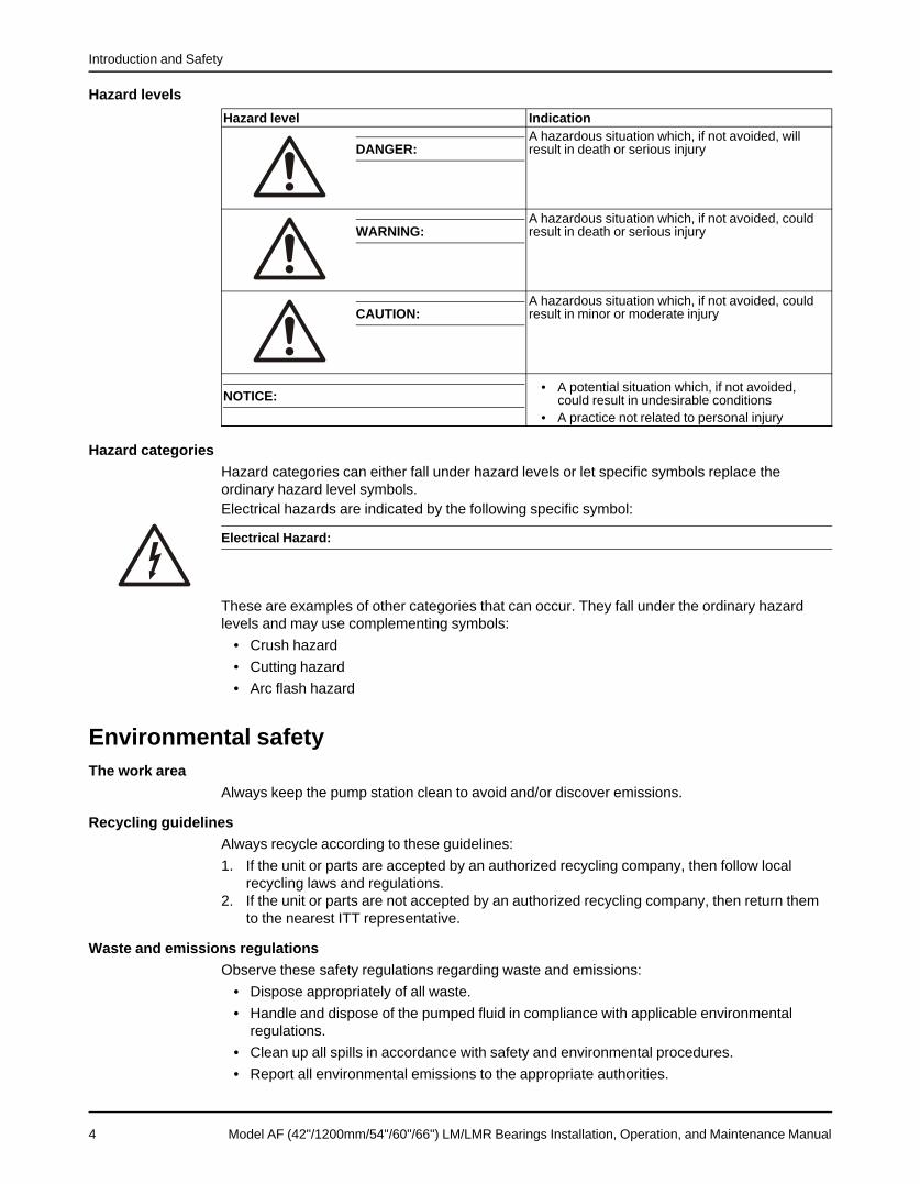
Hazard levelsHazard level Indication
A hazardous situation which, if not avoided, willDANGER: result in death or serious injury
A hazardous situation which, if not avoided, couldWARNING: result in death or serious injury
A hazardous situation which, if not avoided, couldCAUTION: result in minor or moderate injury
• A potential situation which, if not avoided,NOTICE: could result in undesirable conditions• A practice not related to personal injury
Hazard categoriesHazard categories can either fall under hazard levels or let specific symbols replace theordinary hazard level symbols.Electrical hazards are indicated by the following specific symbol:
Electrical Hazard:
These are examples of other categories that can occur. They fall under the ordinary hazardlevels and may use complementing symbols:
• Crush hazard• Cutting hazard• Arc flash hazard
Environmental safetyThe work area
Always keep the pump station clean to avoid and/or discover emissions.
Recycling guidelinesAlways recycle according to these guidelines:1. If the unit or parts are accepted by an authorized recycling company, then follow local
recycling laws and regulations.2. If the unit or parts are not accepted by an authorized recycling company, then return them
to the nearest ITT representative.
Waste and emissions regulationsObserve these safety regulations regarding waste and emissions:
• Dispose appropriately of all waste.• Handle and dispose of the pumped fluid in compliance with applicable environmental
regulations.• Clean up all spills in accordance with safety and environmental procedures.• Report all environmental emissions to the appropriate authorities.
4 Model AF (42"/1200mm/54"/60"/66") LM/LMR Bearings Installation, Operation, and Maintenance Manual

Introduction and Safety
Reference for electrical installationFor electrical installation requirements, consult your local electric utility.
Environmental safetyThe work area
Always keep the station clean to avoid and/or discover emissions.
Waste and emissions regulationsObserve these safety regulations regarding waste and emissions:
• Appropriately dispose of all waste.• Handle and dispose of the processed liquid in compliance with applicable environmental
regulations.• Clean up all spills in accordance with safety and environmental procedures.• Report all environmental emissions to the appropriate authorities.
WARNING:Do NOT send the product to the manufacturer if it has been contaminated by any nuclear radiation. InformITT so that accurate actions can take place.
Electrical installationFor electrical installation recycling requirements, consult your local electric utility.
User safetyGeneral safety rules
These safety rules apply:• Always keep the work area clean.• Pay attention to the risks presented by gas and vapors in the work area.• Avoid all electrical dangers. Pay attention to the risks of electric shock or arc flash hazards.• Always bear in mind the risk of drowning, electrical accidents, and burn injuries.
Safety equipmentUse safety equipment according to the company regulations. Use this safety equipment withinthe work area:
• Helmet• Safety goggles, preferably with side shields• Protective shoes• Protective gloves• Gas mask• Hearing protection• First-aid kit• Safety devices
NOTICE:Never operate a unit unless safety devices are installed. Also see specific informationabout safety devices in other sections of this manual.
Model AF (42"/1200mm/54"/60"/66") LM/LMR Bearings Installation, Operation, and Maintenance Manual 5
Introduction and Safety
Electrical connectionsElectrical connections must be made by certified electricians in compliance with all internation-al, national, state, and local regulations. For more information about requirements, see sectionsdealing specifically with electrical connections.
Precautions before workObserve these safety precautions before you work with the product or are in connection withthe product:
• Provide a suitable barrier around the work area, for example, a guard rail.• Make sure that all safety guards are in place and secure.• Allow all system and pump components to cool before you handle them.• Make sure that you have a clear path of retreat.• Make sure that the product cannot roll or fall over and injure people or damage property.• Make sure that the lifting equipment is in good condition.• Use a lifting harness, a safety line, and a breathing device as required.• Make sure that the product is thoroughly clean.• Make sure that there are no poisonous gases within the work area.• Make sure that you have quick access to a first-aid kit.• Disconnect and lock out power before servicing.• Check the explosion risk before you weld or use electric hand tools.
Precautions during workObserve these safety precautions when you work with the product or are in connection with theproduct:
• Never work alone.• Always wear protective clothing and hand protection.• Stay clear of suspended loads.• Always lift the product by its lifting device.• Beware of the risk of a sudden start if the product is used with an automatic level control.• Beware of the starting jerk, which can be powerful.• Rinse the components in water after you disassemble the pump.
Safety regulations for Ex-approved products in potentiallyexplosive atmospheresGuidelines for compliance
WARNING:This manual clearly identifies accepted methods for disassembling units. These methods must be
adhered to. Trapped liquid can rapidly expand and result in a violent explosion and injury. Never applyheat to impellers, propellers, or their retaining devices to aid in their removal unless explicitly stated in thismanual.
If there are any questions regarding these requirements, the intended use, or if the equipmentrequires modification, contact an ITT representative before you proceed.
Personnel requirementsITT disclaims all responsibility for work done by untrained and unauthorized personnel.
6 Model AF (42"/1200mm/54"/60"/66") LM/LMR Bearings Installation, Operation, and Maintenance Manual
Introduction and Safety
These are the personnel requirements for Ex-approved products in potentially explosiveatmospheres:
• All work on the product must be carried out by certified electricians and ITT-authorizedmechanics. Special rules apply to installations in explosive atmospheres.
• All users must know about the risks of electric current and the chemical and physicalcharacteristics of the gas and/or vapor present in hazardous areas.
• Any maintenance for Ex-approved products must conform to international and nationalstandards (for example IEC/EN 60079-17).
Product and product handling requirementsThese are the product and product handling requirements for Ex-approved products inpotentially explosive atmospheres:
• Only use the product in accordance with the approved motor data stated on thenameplates.
• The Ex-approved product must never run dry during normal operation. Dry running duringservice and inspection is only permitted outside the classified area.
• Before you start working with the product, make sure that the product and the control panelare isolated from the power supply and the control circuit, so they cannot be energized.
• Do not open the product while it is energized or in an explosive gas atmosphere.• Make sure that thermal contacts are connected to a protection circuit according to the
approval classification of the product.• Intrinsically safe circuits are normally required for the automatic level-control system by the
level regulator if mounted in zone 0.• The yield stress of fasteners must be in accordance with the approval drawing and the
product specification.• Do not modify the equipment without approval from an authorized ITT representative.• Only use parts that have been provided by an authorized ITT representative.
Equipment for monitoringFor additional safety, use condition-monitoring devices. Condition-monitoring devices includebut are not limited to these devices:
Product approval standardsRegular standards
Product warrantyCoverage
ITT undertakes to remedy faults in products from ITT under these conditions:• The faults are due to defects in design, materials, or workmanship.• The faults are reported to an ITT representative within the warranty period.• The product is used only under the conditions described in this manual.• The monitoring equipment incorporated in the product is correctly connected and in use.• All service and repair work is done by ITT-authorized personnel.• Genuine ITT parts are used.• Only Ex-approved spare parts and accessories authorized by ITT are used in Ex-approved
products.
Model AF (42"/1200mm/54"/60"/66") LM/LMR Bearings Installation, Operation, and Maintenance Manual 7

Introduction and Safety
LimitationsThe warranty does not cover faults caused by these situations:
• Deficient maintenance• Improper installation• Modifications or changes to the product and installation made without consulting ITT• Incorrectly executed repair work• Normal wear and tear
ITT assumes no liability for these situations:• Bodily injuries• Material damages• Economic losses
Warranty claimITT products are high-quality products with expected reliable operation and long life. However,should the need arise for a warranty claim, then contact your ITT representative.
8 Model AF (42"/1200mm/54"/60"/66") LM/LMR Bearings Installation, Operation, and Maintenance Manual

Transportation and Storage
Transportation and StorageInspect the deliveryInspect the package
1. Inspect the package for damaged or missing items upon delivery.2. Note any damaged or missing items on the receipt and freight bill.3. File a claim with the shipping company if anything is out of order.
If the product has been picked up at a distributor, make a claim directly to the distributor.
Inspect the unit1. Remove packing materials from the product.
Dispose of all packing materials in accordance with local regulations.2. Inspect the product to determine if any parts have been damaged or are missing.3. If applicable, unfasten the product by removing any screws, bolts, or straps.
For your personal safety, be careful when you handle nails and straps.4. Contact your sales representative if anything is out of order.
Transportation guidelinesPump handling
WARNING:• Make sure that the unit cannot roll or fall over and injure people or damage property.• These pumps might use carbon or ceramic silicon carbide components. Do not drop the pump or
subject it to shock loads as this can damage the internal ceramic components.
NOTICE:Use a forklift truck or an overhead crane with sufficient capacity to move the pallet with thepump unit on top. Failure to do so can result in equipment damage.
Lifting the Pump / Sub-BaseWARNING:Pump and components are heavy. Failure to properly lift and support equipment could result in seriousphysical injury or damage to pumps.
Use care when moving pumps. Lifting equipment must be able to adequately support the entireassembly. Lift assembled unit by the lifting holes found in the sub-base. If the motor, sheaves,and guard are in place, be sure that the lifting cable or chain clears these components. Ifnecessary remove the guard or use a spreader bar to prevent damage. In case the motor shipsseparate use the eyebolts or lifting lugs found on the motor to hoist it into place on the sub-base.
Storage guidelinesPump storage requirements
Storage requirements depend on the amount of time that you store the unit. The normalpackaging is designed only to protect the unit during shipping.
Model AF (42"/1200mm/54"/60"/66") LM/LMR Bearings Installation, Operation, and Maintenance Manual 9
Transportation and Storage
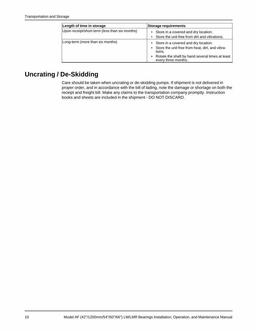
Length of time in storage Storage requirementsUpon receipt/short-term (less than six months) • Store in a covered and dry location.
• Store the unit free from dirt and vibrations.Long-term (more than six months) • Store in a covered and dry location.
• Store the unit free from heat, dirt, and vibra-tions.
• Rotate the shaft by hand several times at leastevery three months.
Uncrating / De-SkiddingCare should be taken when uncrating or de-skidding pumps. If shipment is not delivered inproper order, and in accordance with the bill of lading, note the damage or shortage on both thereceipt and freight bill. Make any claims to the transportation company promptly. Instructionbooks and sheets are included in the shipment - DO NOT DISCARD.
10 Model AF (42"/1200mm/54"/60"/66") LM/LMR Bearings Installation, Operation, and Maintenance Manual
Product Description
Product DescriptionGeneral
This instruction manual is intended to assist those involved with the installation, operation andmaintenance of Gould’s pumps. It is recommended that this manual be thoroughly reviewedprior to installing or performing any work on the pump or motor.The design, material and workmanship incorporated into the construction of Gould’s pumpsmakes them capable of giving long, trouble-free service. The life and satisfactory service of anymechanical unit, however, are enhanced and extended by periodic inspection and carefulmaintenance. Keep this instruction manual handy for reference. Further information can beobtained by contacting Gould’s Pumps, Ashland Operations, East Centre St., Ashland, PA17921 or your local representative.Gould’s Pumps will not be liable for any damages or delay caused by failure to comply with theprovisions of this instruction manual. This pump is not to be operated at speeds, workingpressures, discharge pressures, or temperatures, nor used on liquids other than stated in theoriginal order acknowledgment without written permission of Gould’s Pumps.
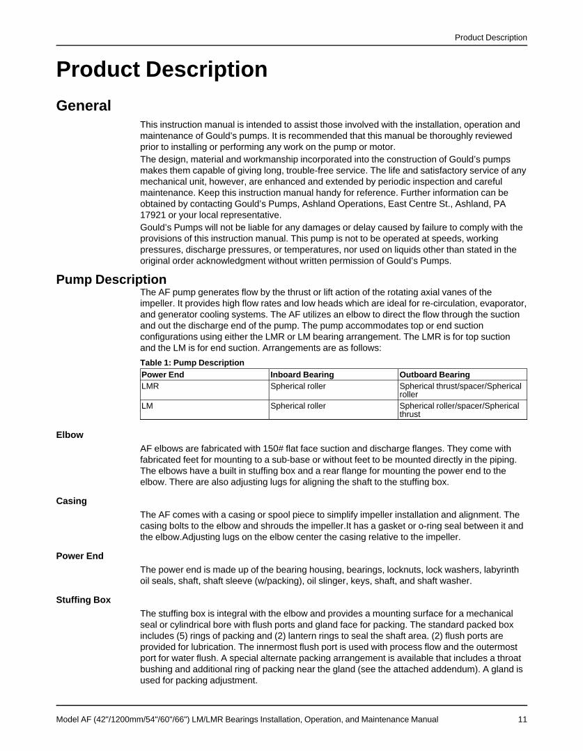
Pump DescriptionThe AF pump generates flow by the thrust or lift action of the rotating axial vanes of theimpeller. It provides high flow rates and low heads which are ideal for re-circulation, evaporator,and generator cooling systems. The AF utilizes an elbow to direct the flow through the suctionand out the discharge end of the pump. The pump accommodates top or end suctionconfigurations using either the LMR or LM bearing arrangement. The LMR is for top suctionand the LM is for end suction. Arrangements are as follows:Table 1: Pump DescriptionPower End Inboard Bearing Outboard BearingLMR Spherical roller Spherical thrust/spacer/Spherical
rollerLM Spherical roller Spherical roller/spacer/Spherical
thrust
ElbowAF elbows are fabricated with 150# flat face suction and discharge flanges. They come withfabricated feet for mounting to a sub-base or without feet to be mounted directly in the piping.The elbows have a built in stuffing box and a rear flange for mounting the power end to theelbow. There are also adjusting lugs for aligning the shaft to the stuffing box.
CasingThe AF comes with a casing or spool piece to simplify impeller installation and alignment. Thecasing bolts to the elbow and shrouds the impeller.It has a gasket or o-ring seal between it andthe elbow.Adjusting lugs on the elbow center the casing relative to the impeller.
Power EndThe power end is made up of the bearing housing, bearings, locknuts, lock washers, labyrinthoil seals, shaft, shaft sleeve (w/packing), oil slinger, keys, shaft, and shaft washer.
Stuffing BoxThe stuffing box is integral with the elbow and provides a mounting surface for a mechanicalseal or cylindrical bore with flush ports and gland face for packing. The standard packed boxincludes (5) rings of packing and (2) lantern rings to seal the shaft area. (2) flush ports areprovided for lubrication. The innermost flush port is used with process flow and the outermostport for water flush. A special alternate packing arrangement is available that includes a throatbushing and additional ring of packing near the gland (see the attached addendum). A gland isused for packing adjustment.
Model AF (42"/1200mm/54"/60"/66") LM/LMR Bearings Installation, Operation, and Maintenance Manual 11
Product Description
Shaft SleeveIf packing is specified, a replaceable wear sleeve is provided with the power end. The sleeve iskeyed to prevent rotation. The stuffing box can also be modified to accept a mechanical seal ifrequired.
ImpellerThe impeller is cast with (4) fixed vanes at 0 or +5 degrees, CW or CCW rotation, and top orend suction. The impeller bore is stepped for easy assembly to the shaft. It is held in place witha key, shaft washer, and bolts. It has a cover plate and o-rings to prevent corrosion and allowfor easy impeller replacement. The impeller is dynamically balanced (two plane) per ISO 1940to a quality grade G-16.
ShaftThe shaft is cantilevered into the elbow to eliminate the need for internal bearings. It is sized forminimal deflection, high critical speed, and extreme corrosion resistance. The shafts arestepped for easy assembly with the impeller. The shaft comes with a replaceable sleeve whenused with stuffing boxes.
BearingsThe inboard radial bearing absorbs shaft radial loads and aligns the pump shaft. It is aspherical roller bearing. The outboard thrust bearing absorbs impeller thrust loads and comesas either back-to-back angular contacts or a single taper roller bearing, depending on pumpsize. Lubrication is by flood oil.
Oil Cooling (Optional)An oil-cooling coil is available on all sizes, it is installed in the bottom of the bearing housingand circulates water to cool the oil bath. Generally, it is used when process temperatures causeexcessive heat build up in the bearing housing and/or bearings.
Configurations and DrivesThe 42", 1200mm, 54", 60", and 66" pumps are usually gear driven and come on a subbase asstandard. They can also be pipe mounted with a drive shaft to a motor on a separate subbase.
Nameplate informationImportant information for ordering
Every pump has nameplates that provide information about the pump. The nameplates arelocated on the bearing housing.When you order spare parts, identify this pump information:
• Model• Size• Serial number• Item numbers of the required parts
Refer to the nameplate on the bearing housing for most of the information. See Parts List foritem numbers.
12 Model AF (42"/1200mm/54"/60"/66") LM/LMR Bearings Installation, Operation, and Maintenance Manual
Product Description
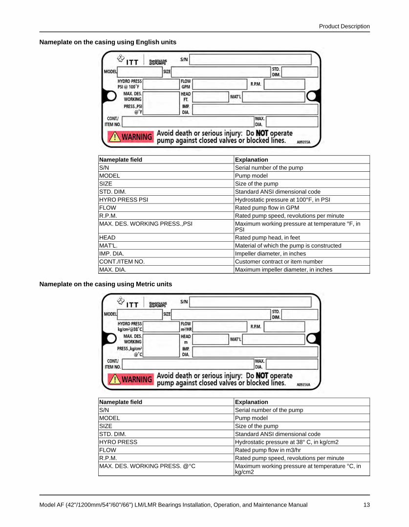
Nameplate on the casing using English units
Nameplate field ExplanationS/N Serial number of the pumpMODEL Pump modelSIZE Size of the pumpSTD. DIM. Standard ANSI dimensional codeHYRO PRESS PSI Hydrostatic pressure at 100°F, in PSIFLOW Rated pump flow in GPMR.P.M. Rated pump speed, revolutions per minuteMAX. DES. WORKING PRESS.,PSI Maximum working pressure at temperature °F, in
PSIHEAD Rated pump head, in feetMAT'L. Material of which the pump is constructedIMP. DIA. Impeller diameter, in inchesCONT./ITEM NO. Customer contract or item numberMAX. DIA. Maximum impeller diameter, in inches
Nameplate on the casing using Metric units
Nameplate field ExplanationS/N Serial number of the pumpMODEL Pump modelSIZE Size of the pumpSTD. DIM. Standard ANSI dimensional codeHYRO PRESS Hydrostatic pressure at 38° C, in kg/cm2FLOW Rated pump flow in m3/hrR.P.M. Rated pump speed, revolutions per minuteMAX. DES. WORKING PRESS. @°C Maximum working pressure at temperature °C, in
kg/cm2
Model AF (42"/1200mm/54"/60"/66") LM/LMR Bearings Installation, Operation, and Maintenance Manual 13
Product Description
Nameplate field ExplanationHEAD Rated pump head, in mMAT'L. Material of which the pump is constructedIMP. DIA. Impeller diameter, in inchesCONT./ITEM NO. Customer contract or item numberMAX. DIA. Maximum impeller diameter, in inches
14 Model AF (42"/1200mm/54"/60"/66") LM/LMR Bearings Installation, Operation, and Maintenance Manual

Installation
InstallationPreinstallation
AF units are usually shipped completely assembled. Check all bolts and nuts on the entire unitand make sure they are securely tightened.If necessary install and adjust drive components per manufacturer’s recommendations
Equipment that will operate in a potentially explosive environment must be installed inaccordance with the following instructions.
All equipment being installed must be properly grounded to prevent unexpected staticelectric discharge. If not, a static electric discharge may occur when the pump is drained anddisassembled for maintenance purposes.
Foundation RequirementsAF pump shall be located in a clean, dry area free from flooding. The area should provideadequate space for operation, maintenance, inspection and repair, considering completedisassembly and handling of equipment. The pump should have a supply of clean liquid forpacking or mechanical seal lubrication. The pump shall be positioned to provide the mostefficient pipeline system.The AF pumps covered by these instructions may be designed to hang in the piping system,furnished with spring loaded sub-base bolts, or have a sub-base designed to be anchor boltedand grouted to the foundation.The foundation must be substantial enough to absorb any vibration and form a permanent, rigidsupport for the pumping unit to the degree that there shall not be any adverse movement orsettling over a long period of time.Foundations for anchor bolted and grouted sub-bases are typically concrete with anchor boltscast in to secure the pump.The most commonly used foundation bolts are the sleeve-type.
Sleeve-type bolts
Figure 1: Sleeve type bolts
1. Baseplate2. Shims or wedges3. Foundation4. Sleeve5. Dam6. Bolt
Model AF (42"/1200mm/54"/60"/66") LM/LMR Bearings Installation, Operation, and Maintenance Manual 15

Installation
J-type bolts
Figure 2: J-type bolts
1. Baseplate2. Shims or wedges3. Foundation4. Dam5. Bolt
Sub-base LevelingGrouted BaseWhen the unit is received with the pump and driver mounted to the sub-base, it should beplaced on the foundation and the coupling halves or V-belts disconnected (see Figure titledSub-base, top view). The coupling should not be reconnected until all realignment operationshave been completed. A recommended coupling alignment procedure is included in thefollowing sections.
Figure 3: Sub-base, top view
Figure 4: Sub-base, side view
1. The sub-base should be supported on rectangular metal blocks or on metal wedges havinga slight taper. There should be support blocks or wedges on both sides of each foundation
16 Model AF (42"/1200mm/54"/60"/66") LM/LMR Bearings Installation, Operation, and Maintenance Manual

Installation
bolt. A gap of about 3/4" (19mm) to 1-1/2" (38mm) should be allowed between the sub-base and the foundation for grouting, see Figure titled Sub-base, side view.
2. Adjust the metal supports or wedges until the shafts of the pump and driver and sub-baseare level. Check the coupling faces, as well as the suction and discharge flanges of thepump, for horizontal and vertical position by means of a level. Check also for any internalrubbing in the pump. Correct, if necessary, by adjusting the supports or wedges under thesub-base as required. In most cases, factory alignment will be regained by shimming underthe sub-base alone. Provisions must be made to support the discharge piping independent-ly from the pump to prevent excessive loads and maintain pump-driver alignment.
3. The sub-base should be level to within .125" (3 mm) over the length of the base and .0875"(1.5 mm) over the width of the base. Bases anchored with conventional foundation boltsuse shims on both sides of the anchor bolts to level the base. The bolts which secure thepump sub-base to the foundation should be 1/8" (3mm) – 1/4" (6mm) less in diameter thanthe holes in the sub-base (hole size is shown on the certified installation drawing).
4. Clean outside areas of sub-base that will contact grout. Do not use oil-based cleanersbecause grout will not bond to it. Refer to grout manufacturer's instructions.
5. Build a dam around foundation and thoroughly wet the foundation.
Figure 5: Build dam around foundation
1. Baseplate2. Shims or wedges3. Foundation4. Sleeve5. Dam6. Bolt
6. Pour grout through the grout holes in the sub-base, up to level of dam. Remove air bubblesfrom grout as it is poured by puddling, using a vibrator, or pumping the grout into place.Non-shrink grout is recommended.
7. Allow grout to set.8. Allow grout to set.9. Allow grout to set at least 48 hours.10. Tighten foundation bolts.
Figure 6: Tighten foundation bolts
Model AF (42"/1200mm/54"/60"/66") LM/LMR Bearings Installation, Operation, and Maintenance Manual 17

Installation
Spring Mounted BaseThe Figure: V-belt Driven AF pump on spring mounted sub-base, shows a V-belt driven AFpump on a spring mounted sub-base. Sub-bases supported by spring pockets assure that thepump remains level, regardless of vertical movement due to thermal pipe expansion duringoperation.
1. Spring pocketsFigure 7: V-belt Driven AF pump on spring mounted sub-base
The following is a brief description of the spring pocket components and their function (seeFigure: Spring pocket components). The adjusting screw is used to compress or relax thespring. Turning the screw causes the adjusting screw nut assembly to move vertically andchange the amount of force the spring exerts against the spring retainer, which is fastened tothe sub-base. The stop nut is to limit the vertical up motion of the sub-base in case part of theload is removed from the pump unit when the system is cold. The jam nut keeps the stop nutfrom turning during normal operation when the sub-base has been pushed down from thethermal expansion. The adjusting screw holder is a bearing surface for the end of the adjustingscrew and serves to hold the end of the screw in a fixed location.
18 Model AF (42"/1200mm/54"/60"/66") LM/LMR Bearings Installation, Operation, and Maintenance Manual

Installation
1. Adjusting screw 6. Spring2. Jam nut 7. Spring holder (welded to sub-base)3. Stop nut 8. Adjusting screw nut assembly4. Spring retainer 9. Lubricate with oil5. Bolts and nuts 10. Adjusting screw holder
Figure 8: Spring pocket components
The adjusting screw was lubricated at the factory but should be re-lubricated with heavyprotective grease during the pump installation. The springs and other parts should be coatedwith an agent to protect the surface from corrosion, and a heavy lubricant should be applied tothe adjusting screw holder pocket.The following steps are used to set the springs and level the sub-base:
Model AF (42"/1200mm/54"/60"/66") LM/LMR Bearings Installation, Operation, and Maintenance Manual 19

Installation
1. Place blocks under the sub-base, near each spring holder, and position the sub-base levelon the blocks. A small gap(approx. 1/16" or 1.6 mm) should exist between the flange of thevertical pipe and the pump elbow with the gasket in place (see Figure: Blocks placed undersub-base).
2. Install several flange bolts to help maintain alignment of the flanges.
Figure 9: Blocks placed under sub-base
WARNING:Do not tighten bolts.
3. Position the adjusting screw holders, while the adjusting screw end is seated in the hole, inthe direction of the horizontal thermal expansion. This will allow the required horizontalmotion without having the adjusting screw nut assembly hit the walls of the spring holder.Make sure there is sufficient clearance between the adjusting screw holder and the bottomof the sub-base for vertical thermal expansion, this clearance is usually shown on the pumpinstallation drawing.
NOTICE: Each spring carries a share of the unit load but generally do not carry equalloads. Each holder has a small "window" to check the spring coil spacing, which is anindication of the relative load on the spring. The installation drawing may indicate theapproximate number of turns required for each spring location, especially if the unit usesmore than (4) springs. If necessary refer to Table: Spring rate information.
Table 2: Spring rate informationSpring Size Wire Size Spring Rate Adjusting Screw Load Change per
Size Full Turn1 .812" 1140 #/in. 1-1/2”-6 UNC 190 #2 .750" 760 #/in. 1-1/2”-6 UNC 127 #3 .532" 560 #/in. 1-1/2”-6 UNC 93 #4 1.00" 1000 #/in. 2”-4-1/2 UNC 222 #5 .375" 133 #/in. ¾”-10 UNC 13 #
4. Turn the adjusting screws until the bottom of the sub-base just clears each block. Nextadjust each screw evenly until the pump flange and gasket are less than 1/32" (0.8 mm)away from the pipe flange. Careful adjustment is necessary to keep the pump level and
20 Model AF (42"/1200mm/54"/60"/66") LM/LMR Bearings Installation, Operation, and Maintenance Manual

Installation
obtain better weight distribution on the springs. After the springs have been loaded andadjusted, the base should be off the support blocks and level.
5. Check the alignment of the impeller and the pump elbow. If necessary, correct thealignment by adjusting the springs or by using shims.
NOTICE: If the flange gap is over 1/32" (0.8 mm) , turn the adjusting screws a uniformamount to close the gap. For a gap of 1/32" (0.8 mm) or less, omit this step.
6. Tighten the vertical pipe flange bolts, recheck the alignment and connect the horizontalpipe flange to the elbow. The pump unit should be level and there should not be anyrubbing of the impeller in the elbow when the shaft is turned by hand.
7. Run each stop nut down to make light contact with the spring retainer. Lock in place byturning the jam nut down tight against the stop nut.
8. Inspect each spring holder to check the gap between the coils of the spring. There must beenough total gap to accommodate the downward thermal expansion of the system withouthaving them compressed solid.
NOTICE: Pumps with oil lubrication should be checked for oil level while thermal expansionis taking place. It may be necessary to add oil to the bearing housing to provide the properoil level to the higher bearing. A line parallel with the sub-base deck through the proper oillevel line will show the correct level at the highest end of the bearing housing. A horizontalline back from that point will establish the proper level mark on the sight gauge.
The system should be operated at normal temperature before the adjusting screw holdersare grouted in place. Some customers operate their units with the adjusting screw holdersungrouted.If it becomes necessary to remove a spring assembly from a spring pocket, for safety thefollowing steps should be strictly adhered to:
Remove Spring from Spring PocketIf it becomes necessary to remove a spring assembly from a spring pocket, for safety thefollowing steps should be strictly adhered to:1. Make sure the spring is relaxed. If the spring cannot be relaxed with the adjusting screw,
the safest method is to pry off the Plexiglas cover and cut the coils using a torch.2. Remove the bolts or cap screws, which fasten the spring retainer to the holder and lift out
the entire assembly.3. When the pump is connected to the system and a spring is removed, there should be
support under the sub-base near the spring location until the spring has been replaced andadjusted. Distortion of the sub-base will affect the pump alignment, and the weight of thecomponents is more likely to cause distortion when the pump is connected to the rigid pipesystem.
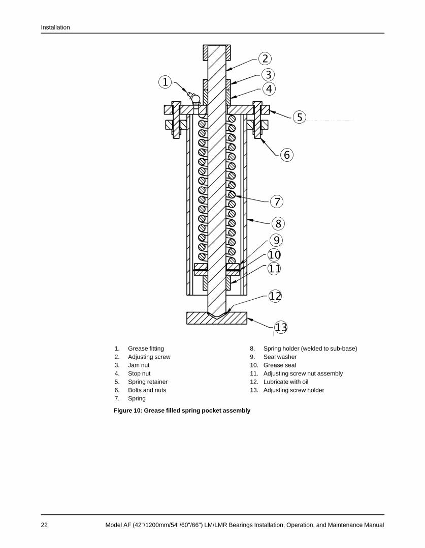
4. If a spring is replaced while the system is hot, the stop nut should not be set until thesystem is cold. The springs must be allowed to push the base back to its cold position.An optional grease filled spring pocket is shown in Figure: Grease filled spring pocketassembly. The difference between the standard pocket and the grease filled pocket is theaddition of a grease fitting and grease seal. Adjustment and setting of the grease filledpocket are identical.
Model AF (42"/1200mm/54"/60"/66") LM/LMR Bearings Installation, Operation, and Maintenance Manual 21
Installation
1. Grease fitting 8. Spring holder (welded to sub-base)2. Adjusting screw 9. Seal washer3. Jam nut 10. Grease seal4. Stop nut 11. Adjusting screw nut assembly5. Spring retainer 12. Lubricate with oil6. Bolts and nuts 13. Adjusting screw holder7. Spring
Figure 10: Grease filled spring pocket assembly
22 Model AF (42"/1200mm/54"/60"/66") LM/LMR Bearings Installation, Operation, and Maintenance Manual
Installation
Connection of PipingGeneral
WARNING:Never draw piping into place by forcing at the flanged connections of the pump. This may imposedangerous strains on the unit and cause misalignment between pump and driver. Pipe strain willadversely effect the operation of the pump resulting in physical injury and damage to the equipment.Guidelines for piping are given in the “Hydraulic Institutes Standards” available from: Hydraulic Institute,30200 Detroit Road, Cleveland OH 44145-1967 and must be reviewed prior to pump installation.
1. All piping must be supported independently of, and line up with the pump flanges.2. Piping runs should be as short as possible to minimize friction losses.3. DO NOT connect piping to the pump until the pump and driver hold-down bolts have been
tightened.4. It is suggested that expansion loops or joints be properly installed in suction and /or
discharge lines when handling liquids at elevated temperatures, so linear expansion ofpiping will not draw pump out of alignment.
5. The piping should be arranged to allow pump flushing prior to removal of the unit onservices handling corrosive liquids.
6. Carefully clean all pipe parts, valves and fittings, and pump branches prior to assembly.
Suction and Discharge Piping
WARNING:Net positive suction head available (NPSHA) must always exceed NPSH required (NPSHR) as shown onthe published performance curve of the pump.
(Reference Hydraulic Institute for NPSH and pipe friction values needed to evaluate suctionpiping)Properly installed suction piping is a necessity for trouble-free pump operation. Suction pipingshould be flushed BEFORE connection to the pump.1. Use of elbows close to the pump suction flange should be avoided. There should be a
minimum of 2 pipe diameters of straight pipe between the elbow and suction inlet. Whereused, elbows should be long radius.
2. Use suction pipe one or two sizes larger than the pump suction, with a reducer at thesuction flange. Suction piping should never be of smaller diameter than the pump suction.
3. To prevent suction cavitation, horizontal reducers should be eccentric with the sloping sidedown and concentric for vertical applications.
4. Pump must never be throttled on suction side.5. Separate suction lines are recommended when more than one pump is operating from the
same source of supply.6. A removable spool piece of a minimum of 1 ft at the connection adjacent to the impeller is
recommended to allow impeller alignment measurements during service activities.Suction lift conditions1. Suction pipe must be free from air pockets.2. Suction piping must slope upwards to pump.3. All joints must be airtight.Suction head/Flooded suction conditions1. An isolation valve should be installed in the suction line at least two pipe diameters from the
suction to permit closing of the line for pump inspection and maintenance.2. Keep suction pipe free from air pockets.3. Piping should be level or slope gradually downward from the source of supply.4. No portion of the piping should extend below pump suction flange.5. The size of entrance from supply should be one or two sizes larger than the suction pipe.6. The suction pipe must be adequately submerged below the liquid surface to prevent
vortices and air entrainment at the supply.
Model AF (42"/1200mm/54"/60"/66") LM/LMR Bearings Installation, Operation, and Maintenance Manual 23

Installation
Discharge piping1. Isolation and check valves should be installed in discharge line. Locate the check valve
between isolation valve and pump, this will permit inspection of the check valve. Theisolation valve is required for priming, regulation of flow, and for inspection andmaintenance of pump. The check valve prevents pump or seal damage due to reverse flowthrough the pump when the driver is turned off.
2. Increasers, if used, should be placed between pump and check valves.3. Cushioning devices should be used to protect the pump from surges and water hammer if
quick-closing valves are installed in system.Final piping check1. Rotate shaft several times by hand to be sure that there is no binding and all parts are free.2. Check alignment, per Impeller alignment worksheet (page 33) to determine absence of
pipe strain. If pipe strain exists, correct the piping.
NOTICE: Prior to starting pump, ensure all flush and cooling systems are operating.
Pipe Hung InstallationLocation of Unit
The pump should be located in a clean, dry area free from flooding. The area should provideadequate space for maintenance and repair, considering complete disassembly and handlingof equipment. The unit should be positioned to provide the most efficient pipeline system.
PipingShort, direct suction and discharge pipelines having a minimum of elbows and fittings will resultin the least amount of pipe friction. Excessive friction losses will result in insufficient capacityand cavitation. Future access to the pump impeller and shaft will require removal of a section ofdischarge pipe (spool piece).
NOTICE:The horizontal pipe flange must be parallel with the pump flange before the bolts are tightened.If the flanges are not parallel, forcing them parallel by tightening the bolts may put excessivestrain on the pump.
Installation of Pump in Pipeline1. Connect the pump top flange to the vertical pipe and tighten flange bolts. Level pump within
.005"/foot (0.42 mm/meter).2. Check the impeller clearance in the casing so that it is reasonably well centered using the
criteria that the minimum gap at the vane.3. O.D. is at least 50% of the maximum gap (see the impeller alignment worksheet).4. Connect the casing flange to the spool piece and tighten the flange bolts.
Installation of the Driver1. Install the driver (motor and reduction gear on a separate sub-base) as indicated on the
installation drawing for the pump. The universal joint drive shaft requires the gear andpump shafts be parallel within 1 degree but off-set as indicated on the drawing. The optimaluniversal joint life is obtained with off-set shaft angles of 1 to 3 degrees.
2. Level the driver base relative to the pump, in accordance with the proceeding paragraphusing leveling wedges adjacent to the anchor bolts. Partially tighten the anchor bolt nutsand check the shaft alignment between the motor and reduction gear. If the alignment isreasonably satisfactory, grout the base in place.
3. After the grout has hardened, tighten the anchor bolt nuts. Check and correct the motorshaft alignment. We recommend the actual shaft misalignment for the flexible couplings be
24 Model AF (42"/1200mm/54"/60"/66") LM/LMR Bearings Installation, Operation, and Maintenance Manual

Installation
considerably less than the maximum allowed by the coupling manufacturer for longcoupling life and reduced vibration levels.
Connection to Pump DriverThe pipe hung pump is connected to the driver via a drive shaft and universal joints at eachend. Follow the drive shaft installation instructions and the angle limits per the pump installationdrawing. An extendable guard is provided for the drive shaft and should be used any time thepump driver is rotating.
1. Level sub-base 7. Vertical pipe2. Motor 8. Pump must be level .005"/ft3. Reduction gear 9. Spool piece4. Extendable guard 10. Horizontal pipe5. Drive shaft 11. Flanges must be parallel6. Flanges must be parallel 12. Shaft off-set +/- 1° to 3°
Figure 11: Connection to pump driver
Drive Alignment ProceduresAlignment procedures must be followed to prevent unintended contact of rotating parts.
Follow coupling manufacturer’s installation and operation procedures.
WARNING:Before beginning any alignment procedure, make sure driver power is locked out. Failure to lock outdriver power will result in serious physical injury.Lock out driver power to prevent electric shock, accidental start-up and physical injury.
The AF pump comes with two drive variations, V-belt and gear driven. Accurate alignment ofboth systems is essential to long pump life and reduced pump problems.The points at which alignment are checked and adjusted are:
• Initial Alignment is done prior to operation when the pump and the driver are at ambienttemperature.
• Final Alignment is done after operation when the pump and driver are at operatingtemperature.
Alignment is achieved by adding or removing shims from under the feet of the driver andgearbox and shifting equipment horizontally by adjusting bolts as needed.
NOTICE:Proper alignment is the responsibility of the installer and user of the unit.
Trouble free operation can be accomplished by following these procedures.Initial Alignment (Cold Alignment)
Model AF (42"/1200mm/54"/60"/66") LM/LMR Bearings Installation, Operation, and Maintenance Manual 25
Installation
• Before Grouting Sub-base - To ensure alignment can be attained. After Grouting Sub-base - To ensure no changes have occurred during the mounting process.
• After Spring Setting – To ensure no changes have occurred during the leveling process.After Connecting Piping - To ensure pipe strains have not altered alignment. If changes haveoccurred, alter piping to remove pipe strains on pump flanges.
• Final Alignment (Hot Alignment)• After First Run - To obtain correct alignment when both pump and driver are at
operating temperature. Thereafter, alignment should be checked periodically in accor-dance with plant operating procedures.
NOTICE:Alignment check must be made if process temperature changes, piping changes, and or pumpservice is performed.
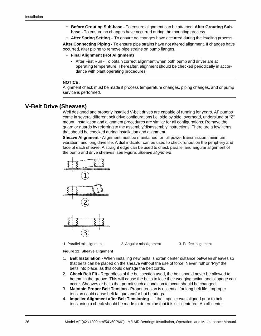
V-Belt Drive (Sheaves)Well designed and properly installed V-belt drives are capable of running for years. AF pumpscome in several different belt drive configurations i.e. side by side, overhead, underslung or “Z”mount. Installation and alignment procedures are similar for all configurations. Remove theguard or guards by referring to the assembly/disassembly instructions. There are a few itemsthat should be checked during installation and alignment.Sheave Alignment - Alignment must be maintained for full power transmission, minimumvibration, and long drive life. A dial indicator can be used to check runout on the periphery andface of each sheave. A straight edge can be used to check parallel and angular alignment ofthe pump and drive sheaves, see Figure: Sheave alignment.
1. Parallel misalignment 2. Angular misalignment 3. Perfect alignment
Figure 12: Sheave alignment
1. Belt Installation - When installing new belts, shorten center distance between sheaves sothat belts can be placed on the sheave without the use of force. Never 'roll' or "Pry" thebelts into place, as this could damage the belt cords.
2. Check Belt Fit - Regardless of the belt section used, the belt should never be allowed tobottom in the groove. This will cause the belts to lose their wedging action and slippage canoccur. Sheaves or belts that permit such a condition to occur should be changed.
3. Maintain Proper Belt Tension - Proper tension is essential for long belt life. Impropertension could cause belt fatigue and/or hot bearings.
4. Impeller Alignment after Belt Tensioning – If the impeller was aligned prior to belttensioning a check should be made to determine that it is still centered. An off center
26 Model AF (42"/1200mm/54"/60"/66") LM/LMR Bearings Installation, Operation, and Maintenance Manual
Installation
impeller may rub and cause unnecessary pump damage. Belt Tension will usually causeimpeller misalignment opposite the motor. Be sure to align or re-align in accordance withthe Impeller Alignment (page 31).
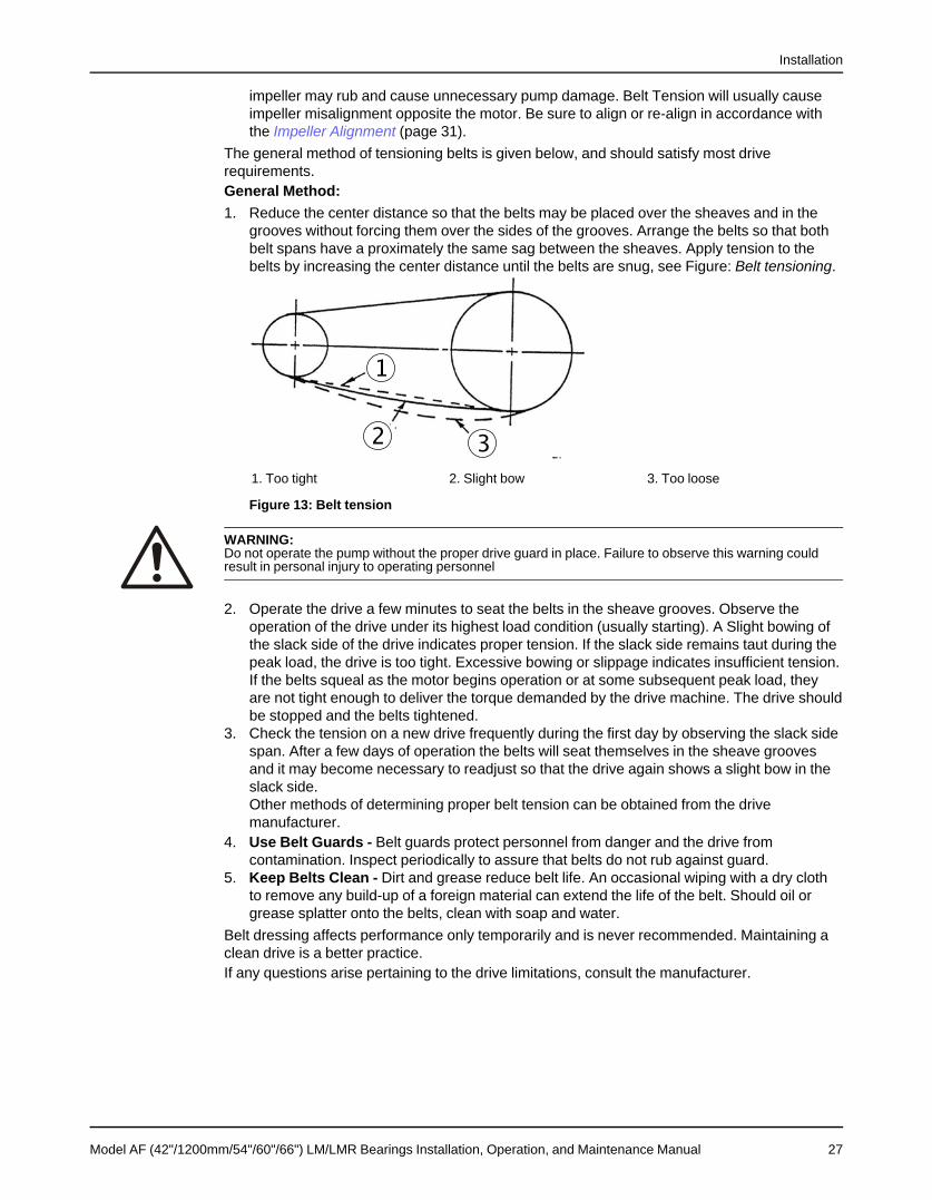
The general method of tensioning belts is given below, and should satisfy most driverequirements.General Method:1. Reduce the center distance so that the belts may be placed over the sheaves and in the
grooves without forcing them over the sides of the grooves. Arrange the belts so that bothbelt spans have a proximately the same sag between the sheaves. Apply tension to thebelts by increasing the center distance until the belts are snug, see Figure: Belt tensioning.
1. Too tight 2. Slight bow 3. Too loose
Figure 13: Belt tension
WARNING:Do not operate the pump without the proper drive guard in place. Failure to observe this warning couldresult in personal injury to operating personnel
2. Operate the drive a few minutes to seat the belts in the sheave grooves. Observe theoperation of the drive under its highest load condition (usually starting). A Slight bowing ofthe slack side of the drive indicates proper tension. If the slack side remains taut during thepeak load, the drive is too tight. Excessive bowing or slippage indicates insufficient tension.If the belts squeal as the motor begins operation or at some subsequent peak load, theyare not tight enough to deliver the torque demanded by the drive machine. The drive shouldbe stopped and the belts tightened.
3. Check the tension on a new drive frequently during the first day by observing the slack sidespan. After a few days of operation the belts will seat themselves in the sheave groovesand it may become necessary to readjust so that the drive again shows a slight bow in theslack side.Other methods of determining proper belt tension can be obtained from the drivemanufacturer.
4. Use Belt Guards - Belt guards protect personnel from danger and the drive fromcontamination. Inspect periodically to assure that belts do not rub against guard.
5. Keep Belts Clean - Dirt and grease reduce belt life. An occasional wiping with a dry clothto remove any build-up of a foreign material can extend the life of the belt. Should oil orgrease splatter onto the belts, clean with soap and water.
Belt dressing affects performance only temporarily and is never recommended. Maintaining aclean drive is a better practice.If any questions arise pertaining to the drive limitations, consult the manufacturer.
Model AF (42"/1200mm/54"/60"/66") LM/LMR Bearings Installation, Operation, and Maintenance Manual 27

Installation
Gear Drive (Couplings)
NOTICE:The coupling used in an ATEX classified environment must be properly certified.
Remove the guard or guards by referring to the assembly/disassembly instructions. Disconnectmotor/gearbox and the pump/gearbox coupling halves before proceeding with the alignment.First, align the pump/gearbox coupling then the motor/gearbox coupling. Check both couplingconnections for parallel and angular alignment by either the Dial Indicator or Straight-EdgeMethod outlined below. Good alignment is achieved when the dial indicator readings, for bothparallel and angular misalignment, are .003" (.076mm) Total Indicated Reading (T.I.R.) or lesswhen the pump and driver are at operating temperature (Final Alignment). Figure: Propercoupling alignment, describes what to look for.
1. Angular misalignment 2. Parallel misalignment 3. Perfect alignment
Figure 14: Proper coupling alignment
1. Mount two dial indicators off one half of the coupling (X) so they contact the other couplinghalf (Y).
1. (Motor End) (Gear box end) 2. (Gearbox end) (Pump end)
Figure 15: Using a dial indicator to check coupling alignment
2. Check setting of indicators by rotating coupling half (X) to ensure indicators stay in contactwith coupling half (Y) but do not bottom out. Adjust indicators accordingly.
28 Model AF (42"/1200mm/54"/60"/66") LM/LMR Bearings Installation, Operation, and Maintenance Manual
Installation
3. To ensure accuracy of indicator readings, always rotate both coupling halves together soindicators contact the same point on coupling half (Y). This will eliminate any measurementproblems due to runout on coupling half (Y).
4. Take indicator measurements with hold-down bolts tightened. Loosen hold down bolts priorto making alignment corrections.
5. Take care not to damage indicators when moving driver during alignment corrections.Keep this instruction manual handy for reference. Further information can be obtained bycontacting Goulds Pumps, 240 Fall St., Seneca Falls, New York 13148 or your localrepresentative.
Alignment ProcedureOn gear driven AF pumps angular and parallel misalignment are corrected in the verticaldirection by means of shims under the motor or gearbox mounting feet, and in the horizontaldirection by adjusting bolts that slide the motor or gearbox in the proper direction.After each adjustment, it is necessary to recheck the alignment of the coupling halves.Adjustment in one direction may disturb adjustments already made in another direction. Itshould not be necessary to adjust the pump in any way.
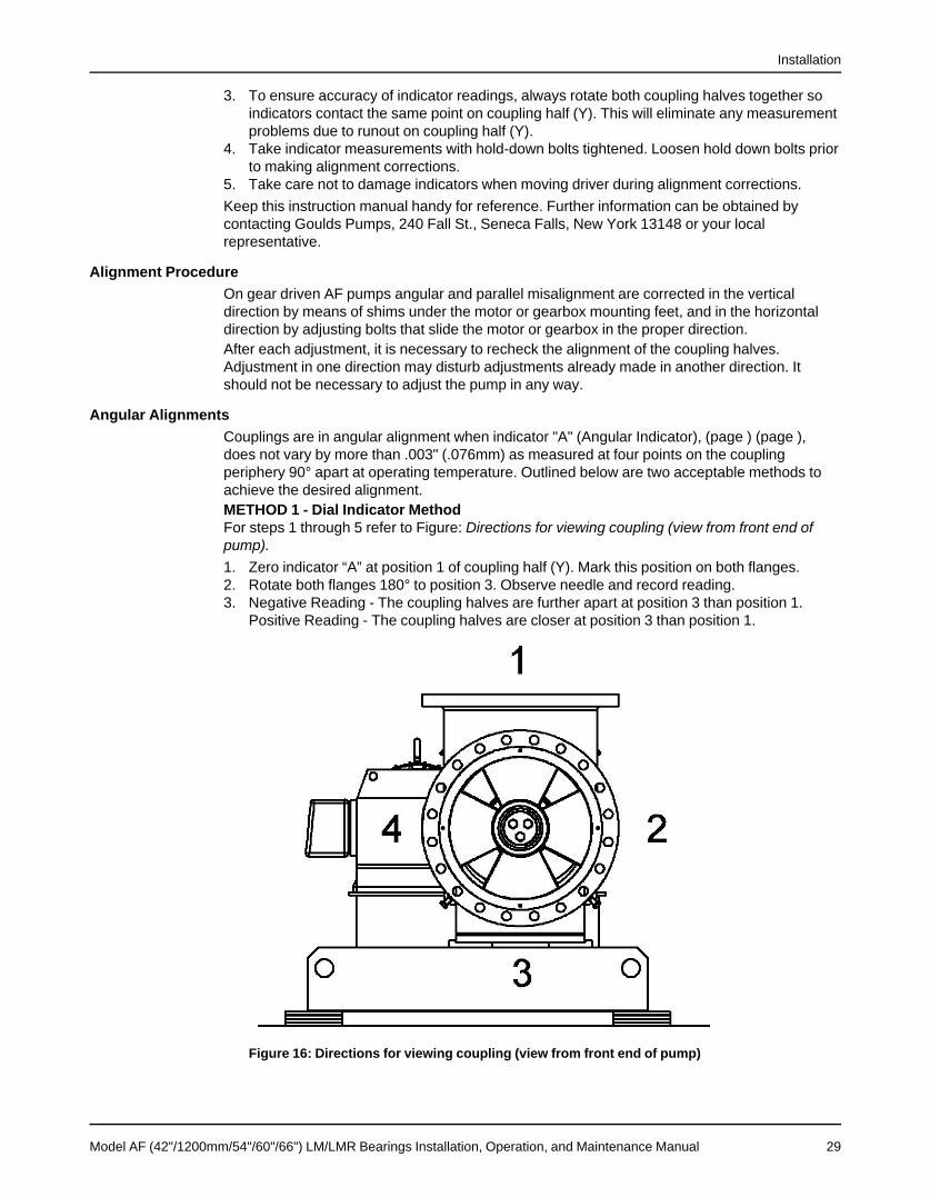
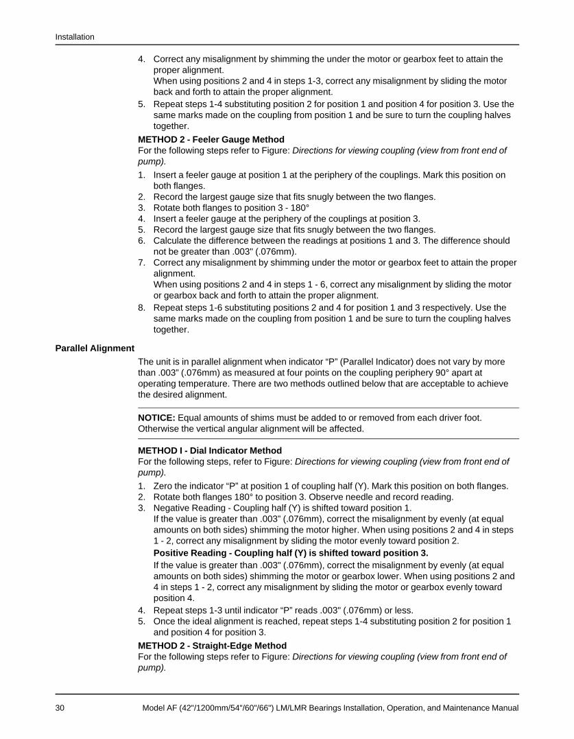
Angular AlignmentsCouplings are in angular alignment when indicator "A" (Angular Indicator), (page ) (page ),does not vary by more than .003" (.076mm) as measured at four points on the couplingperiphery 90° apart at operating temperature. Outlined below are two acceptable methods toachieve the desired alignment.METHOD 1 - Dial Indicator MethodFor steps 1 through 5 refer to Figure: Directions for viewing coupling (view from front end ofpump).1. Zero indicator “A” at position 1 of coupling half (Y). Mark this position on both flanges.2. Rotate both flanges 180° to position 3. Observe needle and record reading.3. Negative Reading - The coupling halves are further apart at position 3 than position 1.
Positive Reading - The coupling halves are closer at position 3 than position 1.
Figure 16: Directions for viewing coupling (view from front end of pump)
Model AF (42"/1200mm/54"/60"/66") LM/LMR Bearings Installation, Operation, and Maintenance Manual 29
Installation
4. Correct any misalignment by shimming the under the motor or gearbox feet to attain theproper alignment.When using positions 2 and 4 in steps 1-3, correct any misalignment by sliding the motorback and forth to attain the proper alignment.
5. Repeat steps 1-4 substituting position 2 for position 1 and position 4 for position 3. Use thesame marks made on the coupling from position 1 and be sure to turn the coupling halvestogether.
METHOD 2 - Feeler Gauge MethodFor the following steps refer to Figure: Directions for viewing coupling (view from front end ofpump).1. Insert a feeler gauge at position 1 at the periphery of the couplings. Mark this position on
both flanges.2. Record the largest gauge size that fits snugly between the two flanges.3. Rotate both flanges to position 3 - 180°4. Insert a feeler gauge at the periphery of the couplings at position 3.5. Record the largest gauge size that fits snugly between the two flanges.6. Calculate the difference between the readings at positions 1 and 3. The difference should
not be greater than .003" (.076mm).7. Correct any misalignment by shimming under the motor or gearbox feet to attain the proper
alignment.When using positions 2 and 4 in steps 1 - 6, correct any misalignment by sliding the motoror gearbox back and forth to attain the proper alignment.
8. Repeat steps 1-6 substituting positions 2 and 4 for position 1 and 3 respectively. Use thesame marks made on the coupling from position 1 and be sure to turn the coupling halvestogether.
Parallel AlignmentThe unit is in parallel alignment when indicator “P” (Parallel Indicator) does not vary by morethan .003” (.076mm) as measured at four points on the coupling periphery 90° apart atoperating temperature. There are two methods outlined below that are acceptable to achievethe desired alignment.
NOTICE: Equal amounts of shims must be added to or removed from each driver foot.Otherwise the vertical angular alignment will be affected.
METHOD I - Dial Indicator MethodFor the following steps, refer to Figure: Directions for viewing coupling (view from front end ofpump).1. Zero the indicator “P” at position 1 of coupling half (Y). Mark this position on both flanges.2. Rotate both flanges 180° to position 3. Observe needle and record reading.3. Negative Reading - Coupling half (Y) is shifted toward position 1.
If the value is greater than .003” (.076mm), correct the misalignment by evenly (at equalamounts on both sides) shimming the motor higher. When using positions 2 and 4 in steps1 - 2, correct any misalignment by sliding the motor evenly toward position 2.Positive Reading - Coupling half (Y) is shifted toward position 3.If the value is greater than .003" (.076mm), correct the misalignment by evenly (at equalamounts on both sides) shimming the motor or gearbox lower. When using positions 2 and4 in steps 1 - 2, correct any misalignment by sliding the motor or gearbox evenly towardposition 4.
4. Repeat steps 1-3 until indicator “P” reads .003" (.076mm) or less.5. Once the ideal alignment is reached, repeat steps 1-4 substituting position 2 for position 1
and position 4 for position 3.METHOD 2 - Straight-Edge MethodFor the following steps refer to Figure: Directions for viewing coupling (view from front end ofpump).
30 Model AF (42"/1200mm/54"/60"/66") LM/LMR Bearings Installation, Operation, and Maintenance Manual

Installation
1. Place a straight edge across the two coupling flanges at position 1 and mark the spot onboth flanges.
2. Adjust the motor or gearbox so that the straight-edge rests evenly on both flanges (within.003" .076mm).
3. Rotate both flanges 90° to positions 2 and repeat steps one and two.4. The unit will be in parallel alignment when the straight edge rests evenly (within .003”
.076mm) on the coupling periphery at both positions along the periphery.
NOTICE: Care must be taken to have the straight edge parallel to the axis of the shafts
Complete AlignmentA unit is in complete alignment when both indicators "A" (angular) and "P" (parallel) do not varyby more than .003" (.076 mm) as measured at four points 90° apart.Vertical Correction (Top-to-Bottom)1. Zero indicators “A” and “P” at top dead center (12 o'clock) of coupling half (Y).2. Rotate indicator to bottom dead center (6 o'clock). Observe the needles and record the
readings.3. Make corrections as outlined previously.
Horizontal Correction (Side-to-Side)1. Zero indicators "A" and "P" on the left side of coupling half (Y), 90° from top dead center (9
o'clock).2. Rotate indicators through, top dead center to the right side, 180° from the start (3 o'clock),
Observe the needle, measure and record the reading.3. Make corrections as outlined previously.4. Recheck both vertical and horizontal readings to ensure adjustment of one did not disturb
the other. Correct as necessary.Factors that may disturb alignmentThe unit should be checked periodically for alignment. If the unit does not stay in line afterbeing properly installed, the following are possible causes:1. Settling or spring of the foundation.2. Wear of bearings.3. Pipe strains distorting or shifting the machine.4. Shifting of the sub-base due to heat created from an adjacent heat source.5. Shifting of the building structure due to variable loading or other causes.6. Loose nuts or bolts on the pump or driver assembly.
NOTICE: With experience, the installer will understand the interaction between angular andparallel and will make corrections appropriately.
Impeller AlignmentImproper impeller adjustment could cause contact between the rotating and stationary
parts, resulting in a spark and heat generation.The impeller clearance setting procedure must be followed. Improperly setting the
clearance or not following any of the proper procedures can result in sparks, unexpected heatgeneration and equipment damage.The AF impeller has been aligned at the factory but should be checked prior to pump operation.The impeller requires several thousandths of and inch of clearance to prevent rubbing due tothe action of hydraulic forces when the pump is operating. Many corrosion-resistant alloys willgall and build up if rubbing occurs, therefore, pumps using these alloys need to be free fromany rubbing.
Model AF (42"/1200mm/54"/60"/66") LM/LMR Bearings Installation, Operation, and Maintenance Manual 31
Installation
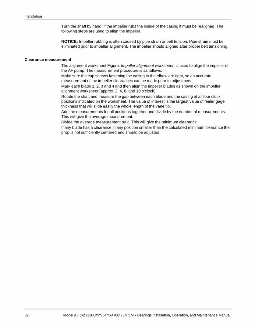
Turn the shaft by hand, if the impeller rubs the inside of the casing it must be realigned. Thefollowing steps are used to align the impeller.
NOTICE: Impeller rubbing is often caused by pipe strain or belt tension. Pipe strain must beeliminated prior to impeller alignment. The impeller should aligned after proper belt tensioning.
Clearance measurementThe alignment worksheet Figure: Impeller alignment worksheet, is used to align the impeller ofthe AF pump. The measurement procedure is as follows:Make sure the cap screws fastening the casing to the elbow are tight, so an accuratemeasurement of the impeller clearances can be made prior to adjustment.Mark each blade 1, 2, 3 and 4 and then align the impeller blades as shown on the impelleralignment worksheet (approx. 2, 4, 8, and 10 o’clock)Rotate the shaft and measure the gap between each blade and the casing at all four clockpositions indicated on the worksheet. The value of interest is the largest value of feeler gagethickness that will slide easily the whole length of the vane tip.Add the measurements for all positions together and divide by the number of measurements.This will give the average measurement.Divide the average measurement by 2. This will give the minimum clearance.If any blade has a clearance in any position smaller than the calculated minimum clearance theprop is not sufficiently centered and should be adjusted.
32 Model AF (42"/1200mm/54"/60"/66") LM/LMR Bearings Installation, Operation, and Maintenance Manual

Installation
Impeller alignment worksheet
Model AF (42"/1200mm/54"/60"/66") LM/LMR Bearings Installation, Operation, and Maintenance Manual 33

Installation
Rotation CheckBefore the V-belts or couplings are installed, the motor should be wired and the direction ofrotation checked. A rotation arrow is located on the bearing housing (134C).Serious damage could occur if the pump is run the wrong direction.
NOTICE:When installing in a potentially explosive environment, make sure that the motor is properly
certified.
Installation and Operation ChecklistTable 3: Installation and Operation ChecklistComplete Initial Description Reference
Manual read and understood AF 42"-66" IOMLevel foundation Foundation Re-
quirements (page15)
Level subbase Sub-base Leveling(page 16)SpringMounted Base(page 18)
Check motor rotation ---CW _____ ---CCW _____ Rotation Check(page 34)
Component rough alignment complete Drive AlignmentProcedures (page25) ~ Gear Drive(Couplings) (page28) ~ Impeller Align-ment (page 31)
V-belt tension and alignment per drive mfgr. V-Belt Drive(Sheaves) (page 26)
Coupling alignment per cplg mfgr. Gear Drive(Couplings) (page28)
Piping installed and alignment rechecked Drive AlignmentProcedures (page25)
Mech. seal adjusted per mfgr. Mfgrs Man’lMech. seal adjusted per mfgr. Final Alignment
(page 42)Impeller alignment and clearance set ______ Inch/Side Impeller Alignment
(page 31)Impelleralignment work-sheet (page 33)
Pump shaft-free turning Preparation forstart-up (page 35)
Bearing lubrication Bearing Mainte-nance (page 44)
V-belt or coupling guards installed Drive AlignmentProcedures (page25)Rotation Check(page 34)
Motor electrical connections Mfgrs Man’l
34 Model AF (42"/1200mm/54"/60"/66") LM/LMR Bearings Installation, Operation, and Maintenance Manual

Commissioning, Startup, Operation, and Shutdown
Commissioning, Startup, Operation, andShutdownPreparation for start-up
NOTICE:When installing in a potentially explosive environment, ensure that the motor is properly
certified.
Damage occurs from:
Checking rotation1. Increased vibration levels-affects bearings, stuffing box or seal chamber and mechanical
seal2. Increased radial loads Stresses on shaft and bearings3. Heat build up-Vaporization causing rotating parts to score or seize4. Cavitation-Damage to internal surfaces of pump
CAUTION:Serious damage may result if pump is run in the wrong direction.
WARNING:Lock out power to prevent accidental start-up and physical injury.
A check must be made to be sure motor rotation coincides with the pump rotation direction.Depending on your pump arrangement (V-belt or gear-drive) use one of the following methodsto check motor rotation.
Direct connect1. Lock out power to the driver.2. Remove the pump coupling guard.3. Make sure the coupling halves are securely fastened to shafts.4. Unlock driver power.5. Make sure everyone is clear. Jog the driver just long enough to determine direction of
rotation of the output shaft of the gearbox. Rotation must correspond to an arrow onbearing housing.
6. Lock out power to driver.7. Replace the pump coupling guard.
NOTICE:The coupling guard used in an ATEX classified environment must be constructed from a
non-sparking material.
V-Belt1. Lock out power to the driver.2. Remove the V-belt guard.3. Make sure the sheaves are securely fastened to shafts.
Model AF (42"/1200mm/54"/60"/66") LM/LMR Bearings Installation, Operation, and Maintenance Manual 35

Commissioning, Startup, Operation, and Shutdown
4. Unlock driver power.5. Make sure everyone is clear. Jog the driver just long enough to determine direction of
rotation. Rotation must correspond to an arrow on bearing housing.6. Lock out power to driver.7. Replace the V-belt guard.
Check Impeller ClearanceCheck impeller clearance before installing the pump. The impeller must not rub when the shaftis turned by hand, therefore it is recommended that the Figure: Impeller Alignment Worksheet,is filled out and filed with the pump maintenance records for future reference.
Check for free turningBefore the pump is started, rotate the pump by hand to be sure it turns freely, and does not rubor bind.
BearingsThe bearing assembly uses spherical roller bearings to carry the radial load, and a sphericalroller thrust bearing to carry the axial thrust load from the impeller. The bearing housing has ahorizontal split along the centerline for ease of assembly and inspection.
LubricationThe bearing uses oil bath lubrication. Oil lubricated bearing assemblies are shipped without oil.Oil must be added to the bearing housing before starting.Table 4: Axial Flow Pump Approx Oil Volume
Pump Size Quarts Liters42" / 1200mm / 54" 74 70.5
60" / 66" 62 59
Approximate values only. Always fill using sight glass to verify level. Oil level should be at thecenter of the sight glass. See comments in this section.Remove the bearing housing breather (113A) and add oil until oil level is at the center of thesight glass. If the unit has an external oil lube system, fill the bearing housing and the reservoirto satisfy the system requirements. Replace the breather. Table: Axial Flow Pump Approx OilVolume, shows the oil volume required.
Bearings must be lubricated properly in order to prevent excess heat generation, sparksand premature failure. Run the pump for 1 minute to fill the oil galleys and in and around eachbearing. Check the sight glass and add oil accordingly. Monitor the oil level indicator for the first24 hours of operation and maintain fill level.
Oil TypeUse an industrial quality lubrication oil such as Mobil DTE series, Exxon Teresstic, or similar ofISO VG68. ISO VG46 may be used in ambient temperatures below 40°F (4°C).In any case the operating temperature viscosity must be a minimum of 150SSU.An oil with a higher viscosity than required will increase the bearing operating temperaturebecause of the extra viscous drag, but never to the point where the viscosity becomes lowerthan required from the increased heat generation. It is therefore better for the bearings to havean oil that is too heavy rather than too light.Change the oil after the first 200 hours of operation. For normal operating conditions, changethe oil at least four (4) times a year. If the bearing assembly is exposed to dirty or moistconditions, the oil should be changed more often.
Oil level controlIf the level of oil in the bearing housing (134C) is too high, excessive heat may be generateddue to churning. If the level is too low, excessive heat may be generated due to inadequatelubrication. A liquid level switch connected to the oil sump can be used to warn of a dangerousoil level condition.
36 Model AF (42"/1200mm/54"/60"/66") LM/LMR Bearings Installation, Operation, and Maintenance Manual

Commissioning, Startup, Operation, and Shutdown
Observe the oil level requirements shown on the assembly drawing furnished with the pump. Ifexcessive heat is experienced within these levels, consult the factory. Be sure that the shaftcenterline is horizontal through the bearing housing
Normal bearing temperatureThe running temperature for a bearing assembly depends on many factors such as speed,bearing loads, lubrication, ambient air temperatures, and condition of bearings. Temperatureshigher than the human hand can tolerate are very satisfactory for temperature and should notbe cause for alarm. Sudden change in temperature without any change in speed or loading canmean a lubrication difficulty or the approach of bearing failure.For a given speed and loading, the bearing housing temperature will stabilize at sometemperature, usually below 200°F (93°C)., which will be the normal temperature for theinstallation. Higher temperatures than this normal temperature, without any change in speed orloading can mean a lubrication difficulty or the approach of bearing failure.
Installing bearingLong bearing life is dependent on careful handling of the bearing when it is out of the housingand during the installation procedure. Dirt and rough handling are prime enemies of precisionbearings. Bearings should be pressed, not “hammered” into place. If heat is used to facilitatethe installation, a hot oil bath is the best method.
CAUTION:Wear insulated gloves when you use a bearing heater. Bearings get hot and can cause physical injury.
Thrust bearing orientation42-54 (Top Suction) AF with LMR Bearings (page 68) shows the axial thrust bearing (112C) inthe outboard location. This is used for top suction pumps.End suction pumps have the flow and axial thrust in the opposite direction. Therefore, thecomplete thrust bearing assembly is reoriented in the opposite direction. This does not changethe basic disassembly procedure, other than the sequence of installing the thrust bearingassembly components on the shaft.The illustration shows the thrust bearing (112C) mounted on a sleeve (196). For the otherbearing orientation, the bearing is mounted on an extension of the spacer (443), eliminating theseparate sleeve.
Shaft sealingA packed stuffing box or mechanical seal is used to seal the AF pump shaft. Both methods aredescribed below.
Packed stuffing boxThe original equipment packing is a suitable grade for the service intended. To pack thestandard stuffing box use the following procedure: For the special (6) ring packing arrangementsee the appendix 1.1. Stuffing box and shaft sleeve must be clean and free of grit.
For a given speed and loading, the bearing housing temperature will stabilize at sometemperature, usually below 200°F (93°C)., which will be the normal temperature for theinstallation.
2. Form packing over shaft or mandrel of same diameter. Carefully cut to packing length.Discard rings cut too short.
3. Pre-form each ring by coiling 1-1/2 turns.4. To install packing rings, do not pull straight. Expand the coil as a coil spring, see Figure:
Packing rings, for the correct and incorrect method of installing packing.
Model AF (42"/1200mm/54"/60"/66") LM/LMR Bearings Installation, Operation, and Maintenance Manual 37

Commissioning, Startup, Operation, and Shutdown
Correct Incorrect
Figure 17: Packing rings
Expand the first coil as shown and insert into stuffing box. Tamp packing to stuffing boxshoulder firmly with the gland. Note, where the cut is positioned.
5. Install the first lantern ring into the stuffing box. Failure to property locate the lantern ringwith the flush port will result in insufficient packing lubrication.
6. Install the second and third coil as required by sectional drawing, staggering the cut 90° to120°.
7. Install the second lantern ring into stuffing box, carefully noting its proper position on thesectional drawing.
8. Install the third and fourth coil as required by sectional drawing, staggering the cut 90° to120°.
9. After packing and lantern rings are properly installed, insert gland into stuffing box. Tightengland nuts finger tight only. The shaft should turn freely.
10. Turn lubricant supply on, start pump, and adjust the gland as described in Section III-EStuffing Box Adjustment.
11. Periodic maintenance is absolutely required for all packed pumps. Normal shaft run-outshould be under .005" (.13mm) to avoid pounding of stuffing box packing. With excessiveshaft run-out, shaft straightening or replacement is necessary.
Gland adjustmentAdjust the stuffing box if packing is used. When the pump is first started, there should beconsiderable leakage by the gland to cool the packing. Gradually tighten the gland nuts on flatat a time while observing the leakage and stuffing box temperature. Packing requires time to"run-in" and extra coolant (leakage) while it is being "run-in". If the leakage is reduced tooquickly, the packing will overheat and may be destroyed. The shaft sleeve may also bedamaged.
LeakageNormal leakage for a properly adjusted box, depending on shaft size and speed, varies from afew drops a second to a small trickle out of the gland.
Mechanical sealThe mechanical seal used in an ATEX classified environment must be properly certified.
The mechanical seal must always be properly flushed. Failure to do so will result in excessheat generation and seal failureMost mechanical seals are installed and adjusted at the factory. A common seal type used onthe AF pump is the cartridge type. Cartridge seals are preset at the seal manufacturer’s facilityand require no field settings. Due to size and design, some installed mechanical seals aresupplied with holding clips. These clips keep the sealing faces apart to avoid damage duringtransport. The clips must be removed before the shaft is to be rotated. Pumps with retainedseal faces will be specifically marked and instructions from the seal manufacturer for clipremoval will be provided.If the seal has been installed in the pump at the Goulds Pumps factory, these clips havealready been removed. For other types of mechanical seals, refer to the seal manufacturer’sinstructions for installation and setting.
38 Model AF (42"/1200mm/54"/60"/66") LM/LMR Bearings Installation, Operation, and Maintenance Manual
Commissioning, Startup, Operation, and Shutdown
Mechanical seals have a stationary and a rotating sealing face. Commonly, these sealing ringsare of carbon and ceramic material, brittle in nature, and easily damaged. As the sealing ringsseat with the operation of the pump, a compatible wear pattern develops between the matingsurfaces.To disassemble the mechanical seal after the wear pattern is established would necessitate thereplacement of the rotating element and stationary sealing elements. Do not replace only onecomponent.To ensure the life and sealing characteristics of the mechanical seal, lubricating liquid must becirculated through the seal gland. Clear, grit-free liquid is necessary. Goulds Pumps stronglyrecommends the stocking of replacement sealing elements.
WARNING:Do not make shaft adjustments on mechanical seal installations without consulting seal instructions andthe pump assembly drawing. Damage to the mechanical seal may result.
Dynamic seals are not allowed in an ATEX classified environment.
Start the PumpPriming the pump
Pumps that are not self-priming must be fully primed at all times during operation.
DANGER:All openings (e.g. pipe connections, flanges) must be sealed off with proper fitting and material prior tofilling pump. Failure to plug all openings will result in personal injury.
WARNING:Foreign objects in the pumped liquid or piping system can block the flow and cause excess heatgeneration, sparks and premature failure. Make sure that the pump and systems are free of foreignobjects before and during operation.
WARNING:If pump becomes plugged, shut down pump and unplug prior to restarting.
CAUTION:1. Foreign objects in the pumped liquid or piping system can block the flow and cause excess heat
generation, sparks and premature failure. Make sure that the pump and systems are free of foreignobjects before and during operation.
2. All equipment and personal safety related devices and controls must be installed and operatingproperly.
3. To prevent premature pump failure at initial start up due to dirt or debris in the pipe system, ensurethe system has been adequately cleaned and flushed.
4. Variable speed drivers should be brought to rated speed as quickly as possible.5. Variable speed drivers should not be adjusted or checked for speed governor or overspeed trip
settings while coupled to the pump at initial start up If settings have not been verified, uncouple theunit and refer to driver manufacturers instructions for assistance.
6. Pumpage tempertatures in excess of 200°F (93°C) will require warmup of pump prior to operation.Circulate a small amount of pumpage through the pump until the casing temperature is within 100°F(38°C) of the pumpage temperature and evenly heated.
When starting pump, immediately observe pressure gauges. If discharge pressure is not quicklyattained, stop driver, re-prime and attempt to restart.
7. Never start the pump until it has been properly primed. Check the pump impeller for submergence.The pump must be full of liquid with specified submergence head above the impeller. Do not run thepump dry, as this might damage pump and seal components.
8. Lubricating liquid must be flowing to the stuffing box before pump is started.
Model AF (42"/1200mm/54"/60"/66") LM/LMR Bearings Installation, Operation, and Maintenance Manual 39

Commissioning, Startup, Operation, and Shutdown
Flush flowsPrior to starting pump, ensure all flush and cooling systems are operating.Packing or mechanical seals are used to seal the rotating shaft. Generally, a clear liquid suchas water is used to lubricate and cool the sealing elements. The lubricating liquid pressuremust be 10 -15 psi higher than the pressure inside the elbow to prevent pumpage from enteringthe sealing elements. The lubricating liquid must be clean and free of grit. Shaft scoring,packing destruction, and mechanical seal face damage will result from contaminated lubricant.The stuffing box may be on the suction or the discharge side of the impeller, depending on thedirection of flow through the elbow ordered by the customer. If the pressure inside the elbow isunknown, it should be measured with a pressure gauge when the pump is operating. Thestandard stuffing box is furnished with (2) N.P.T. holes for piping the lubricating liquid. Thelubricating liquid is piped into one of them. Some users simply plug the other hole. Foradditional cooling of the sealing elements, an outlet pipe with a valve can be installed to allowmore liquid to flow through the stuffing box.For special (6) row packing arrangement see appendix 1 at the end of this manual for flushpressures and flow rates.(Mechanical seals have no leakage and usually require a lubricant flow through the stuffing boxfor cooling). The lubricating flow should be regulated by the valve in the outlet pipe rather thanby throttling the flow in the supply pipe.
DriverStart driver.
CAUTION:Immediately observe the pressure gauges. If discharge pressure is not quickly attained, stop the driver,reprime, and attempt to restart the pump.
Set desired flowIf your system is equipped with a variable frequency drive (VFD) or a variable speed V-beltdrive, you may at this point want to set your speed for the desired flow.
CAUTION:Observe the pump for vibration levels, bearing temperature, and excessive noise. If normal levels areexceeded, shut down the pump and resolve the issue.
OperationGeneral considerations
Service temperature in an ATEX classified environment is limited by the table in the ATEXidentification section.1. Do not operate pump below hydraulic minimum flow. For hydraulic minimum flow, refer to
technical manual and pump performance curve.2. Do not operate pump below hydraulic or thermal minimum flow. For hydraulic minimum
flows refer to technical manual and pump performance curves. To calculate thermalminimum flow, refer to HI Centrifugal Pump Design and Application ANSI/HI 1.3-2000.
3. Do not operate pump past maximum flow. For maximum flow refer to pump performancecurve.
4. Observe the pump for vibration levels, bearing temperature, and excessive noise. If normallevels are exceeded, shut down the pump and resolve the issue.
5. Make sure to operate the pump at or near the rated conditions. Failure to do so can result inpump damage from cavitation or recirculation.
40 Model AF (42"/1200mm/54"/60"/66") LM/LMR Bearings Installation, Operation, and Maintenance Manual
Commissioning, Startup, Operation, and Shutdown
6. Vary the capacity with the regulating valve in the discharge line. Never throttle the flow fromthe suction side since this can result in decreased performance, unexpected heatgeneration, and equipment damage.
7. Net positive suction head available (NPSHA) must always exceed NPSH required (NPSHR)as shown on the published performance curve of the pump.
8. NPSHa must always exceed NPSHr as shown on Goulds performane curves received withorder.
9. Reference Hydraulic Institute for NPSH and pipe friction values needed to evaluate suctionpiping.
10. Most axial flow pumps are in evaporator circulation service and since the evaporatorperformance and the amount of product depends on the rate of liquid circulation, careshould be taken to maintain these pumps in good operating condition.When production drops off, it is usually due to lower circulation rate. An approximation ofthis rate can be made by several methods:1. Temperature drop across the heat exchanger.2. Visual inspection of flow in evaporator body.3. Testing the circulating pump.
11. Items (1) and (2) above are covered by the evaporator manufacturer.12. While field conditions preclude absolute accuracy, a check of pump performance will give
reasonably close results. This can be done by installing a mercury manometer at pipe tapslocated at least-one pipe diameter away from the suction and discharge flanges of thepump. If-gauges are used, the pressure differential times 2.31 divided by the specificgravity of the slurry indicates the TDH against which the pump is actually operating. If amanometer is used, then inches of mercury times 1.0455 divided by specific gravity equalsTDH, providing water is in both legs of the manometer and connecting lines.
13. Check the pump speed and determine flow rate (gpm) from the pump curve. This curve willalso give efficiency from which the hp requirement can be determined. A double check is totake motor ammeter readings, convert to hp, figure 90% drive efficiency, and use it againstthe pump curve to get GPM. This is only an approximate check, as the hp curve on someapplications is rather flat, but is probably within 7-1/2%. It is important to take and recordthese readings when the equipment is new, so that later readings can be judged on arelative basis.
Operating at reduced capacity
WARNING:Do not operate the pump below the minimum rated flows or with the suction or discharge valves closed.These conditions can create an explosive hazard due to vaporization of pumped fluid and can quickly leadto pump failure and physical injury.
Driver may overload if the pumpage specific gravity (density) is greater than originallyassumed, or the actual flow is much less than the rated flow.The pump and system must be free of foreign objects. If pump becomes plugged, shut downand unplug prior to restarting pump.Listed below are some causes for circulation loss. Keep in mind that operation at reducedcapacities can cause damage to the pump.1. Increase in TDH against which pump operates could be caused by:
1. Heat exchanger tubes partially plugged.2. Too many heat exchanger tubes blanked off3. Improperly sized or partially plugged strainer.
2. Viscosity of slurry higher than it should be.3. Pump speed low. V-belt drive may be slipping and operating pump below design speed.4. Pump throttled on suction side. This could be caused by:
1. rubber lining pulling away from the suction pipe and partially collapsing,2. large solids dropping into the suction, or
Model AF (42"/1200mm/54"/60"/66") LM/LMR Bearings Installation, Operation, and Maintenance Manual 41
Commissioning, Startup, Operation, and Shutdown
3. by an improperly sized or-plugged strainer in the suction pipe.5. Pump partially plugged by large solid jammed between two impeller blades. This will also
cause rough operation with excessive vibration.6. Incorrect pump rotation. When changing motors for any reason or after any electrical
system changes or modifications, always check motors for correct direction of rotation.7. Worn pump impeller and/or casing. On a new pump, clearance between tip of impeller
blade and casing is carefully determined. As this clearance increases, pump performancedecreases.
It is not practical to predict performance at any given clearance without running a test at thisclearance. On small pumps, this effect is magnified as the percentage of impeller blade arealost from wear and corrosion is higher.Other pump conditions and possible causes are:High HP demand1. Increased head or viscosity2. Pump speed too high3. Specific-gravity of slurry higher-than normal4. Packing gland pulled up too tight5. Impeller rubbing in casingNoisy or rough operation1. Throttled suction or plugging2. Impeller rubbing in casingDamage occurs from:1. Increased vibration levels - Affects bearings, stuffing box seal chamber, and mechanical
seals.2. Heat build up - Vaporization causing rotating parts to score or seize.3. Cavitation - Damage to internal surfaces of pump.4. Loose impeller5. Broken impeller blade6. Bearings not properly lubricated7. Bent shaft8. 8. Impeller out of balance.Operating under freezing conditionsExposure to freezing conditions, while pump is idle, could cause liquid to freeze and damagethe pump. Liquid inside pump should be drained.
Shut down the pump1. Turn off power to pump motor.2. In case of necessary maintenance or pump inspection, lock driver to prevent accidental
rotation.
WARNING:When handling hazardous and/or toxic fluids, skin and eye protection are required. If pump is beingdrained, precautions must be taken to prevent physical injury. Pumpage must be handled and disposed ofin conformance with applicable environmental regulation.
Final Alignment1. Run the pump under actual conditions for a sufficient length of time to bring the pump and
driver up to operating temperature.2. Check alignment per alignment procedure outlined earlier.
42 Model AF (42"/1200mm/54"/60"/66") LM/LMR Bearings Installation, Operation, and Maintenance Manual
Maintenance
MaintenancePreventative Maintenance
A routine maintenance program can extend the life of your pump. Well maintained equipmentwill last longer and require fewer repairs. You should keep maintenance records, this will helppinpoint causes of problems.
Condition monitoring
For additional safety precautions, and where noted in this manual, condition monitoringdevices should be used.
• Pressure gauges • Temperature detectors
• Flow meters • Bearing monitors
• Level indicators • Leak detectors
• Motor load readings • PumpSmart control system
For assistance in selecting the proper instrumentation and its use, please contact your ITT/Goulds representative.
Maintenance schedule
NOTICE:The preventive maintenance section must be adhered to in order to keep the applicable
ATEX classification of the equipment. Failure to follow these procedures will void the ATEXclassification for the equipment.
Inspection intervals should be shortened appropriately if the pumpage is abrasive and/orcorrosive, or if the environment is classified as potentially explosive.
NOTICE:When handling hazardous and / or toxic fluids, proper personal protective equipment should beworn. If pump is being drained, precaution must be taken to prevent physical injury. Pumpagemust be handled and dispersed of in conformance with applicable environment regulations.
Maintenance inspectionsA maintenance schedule includes these types of inspections:
• Routine maintenance• Routine inspections• Three-month inspections• Annual inspections
Shorten the inspection intervals appropriately if the pumped fluid is abrasive or corrosive or ifthe environment is classified as potentially explosive.
Routine maintenancePerform these tasks whenever you perform routine maintenance:
• Lubricate the bearings.• Inspect the seal.• Perform a vibration analysis.
Model AF (42"/1200mm/54"/60"/66") LM/LMR Bearings Installation, Operation, and Maintenance Manual 43

Maintenance
• Monitor the discharge pressure.• Monitor the temperature.
Routine inspectionsPerform these tasks whenever you check the pump during routine inspections:
• Check for unusual noise, vibration, and bearing temperatures.• Check the pump and piping for leaks.• Analyze the vibration.• Check the seal chamber and stuffing box for leaks.
• Ensure that there are no leaks from the mechanical seal.• Adjust or replace the packing in the stuffing box if you notice excessive leaking. Refer to
"packing gland adjustment".
Three-month inspectionsPerform these tasks every three months:
• Check that the foundation and the hold-down bolts are tight.• Check the packing if the pump has been left idle, and replace as required.• Change the oil every three months (2000 operating hours) at minimum.
• Change the oil more often if there are adverse atmospheric or other conditions thatmight contaminate or break down the oil. Or if it is cloudy or contaminated as seenthrough the sight glass
• If any rubbing noise has been noticed, re-align the impeller.
Annual inspectionsPerform these inspections one time each year:
• Check the pump capacity.• Check the pump pressure.• Check the pump power.
If the pump performance does not satisfy your process requirements, and the processrequirements have not changed, then perform these steps:1. Disassemble the pump.2. Inspect it.3. Replace worn parts.
WARNING:A worn propeller and/or pump housing can have very sharp edges. Wear protective gloves.
Bearing MaintenanceOperation of the unit without proper lubrication will cause bearing failure, and pump
seizure.Throughout this section on bearing lubrication, different pumpage temperatures are listed.
If the equipment is ATEX certified and the listed temperature exceeds the applicable valueshown in the table under ATEX identification, then that temperature is not valid. Should thissituation occur, please consult with your ITT/Goulds representative.
Oil Lubricated Bearings1. Remove the bearing housing breather (113A) and add oil until oil level is at the center of the
sight glass.
44 Model AF (42"/1200mm/54"/60"/66") LM/LMR Bearings Installation, Operation, and Maintenance Manual

Maintenance
2. If the unit has an external oil lube system, fill the bearing housing and the reservoir tosatisfy the system requirements.
3. Replace the breather.Refer to Oil Volume table for required oil volume.Table 5: Axial Flow Pump Approximate Oil Volume
Pump Size Quarts Litres42" / 1200mm / 54" 74 70.5
60" / 66" 62 59
Approximate values only. Always fill using sight glass to verify level. Oil level should be atthe center of the sight glass. See comments in this section.
Bearings must be lubricated properly in order to prevent excess heat generation,sparks and premature failure.
4. Run the pump for 1 minute to fill the oil galleys and in and around each bearing. Check thesight glass and add oil accordingly. Monitor the oil level indicator for the first 24 hours ofoperation and maintain fill level.
Acceptable oil for lubricating bearingsA good SAE#30 or #40 is usually satisfactory. Consult a reputable supplier for acceptablesubstitutes for the oils mentioned. The viscosity of the oil should be 150 SSU at the operatingtemperature to prevent accelerated bearing wear 150°F (66°C) is the maximum temperature atwhich a typical 30 wt. oil will supply the required viscosity.A good SAE#30 or #40 is usually satisfactory. Consult a reputable supplier for acceptablesubstitutes for the oils mentioned. The viscosity of the oil should be 150 SSU at the operatingtemperature to prevent accelerated bearing wear 150°F (66°C) is the maximum temperature atwhich a typical 30 wt. oil will supply the required viscosity.
Operating temperature Oil requirementbelow 150°F (66°C) SAE 30
150-160°F (66-71°C) SAE 40160-180°F (71-82°C) SAE 50
An oil with a higher viscosity than required will increase the bearing operating temperaturebecause of the extra viscous drag, but never to the point where the viscosity becomes lowerthan required from the increased heat generation. It is therefore better for the bearings to havean oil that is too heavy rather than too light.Change the oil after the first 200 hours of operation. For normal operating conditions, changethe oil at least four (4) times a year. If the bearing assembly is exposed to dirty or moistconditions, the oil should be changed more often.
Oil Level ControlIf the level of oil in the bearing housing (134C) is too high, excessive heat may be generateddue to churning. If the level is too low, excessive heat may be generated due to inadequatelubrication. A liquid level switch connected to the oil sump can be used to warn of a dangerousoil level condition.Observe the oil level requirements shown on the assembly drawing furnished with the pump. Ifexcessive heat is experienced within these levels, consult the factory. Be sure that the shaftcenterline is horizontal through the bearing housing.
Normal Bearing TemperatureThe running temperature for a bearing assembly depends on many factors such as speed,bearing loads, lubrication, ambient air temperatures, and condition of bearings. Temperatureshigher than the human hand can tolerate are very satisfactory for good bearing operation andshould not cause any alarm.For a given speed and loading, the bearing housing temperature will stabilize at sometemperature, usually below 200°F (93°C), which will be the normal temperature for the
Model AF (42"/1200mm/54"/60"/66") LM/LMR Bearings Installation, Operation, and Maintenance Manual 45

Maintenance
installation. Higher temperatures than this normal temperature, without any change in speed orloading can mean a lubrication difficulty or the approach of bearing failure.
Shaft-seal maintenanceMechanical-seal maintenance
WARNING:The mechanical seal used in an Ex-classified environment must be properly certified. Prior to startup,
make sure that all areas that could leak pumped fluid to the work environment are closed.
CAUTION:Never operate the pump without liquid supplied to mechanical seal. If you run a mechanical seal dry,even for a few seconds, this can cause seal damage. Physical injury can occur if a mechanical seal fails.
Cartridge-type mechanical sealsCartridge-type mechanical seals are commonly used. Cartridge seals are preset by the sealmanufacturer and require no field settings. Cartridge seals installed by the user requiredisengagement of the holding clips prior to operation, allowing the seal to slide into place. If theseal has been installed in the pump by ITT, these clips have already been disengaged.
Other mechanical seal typesFor other types of mechanical seals, refer to the instructions provided by the seal manufacturerfor installation and setting.
Reference drawingThe manufacturer supplies a reference drawing with the data package. Keep this drawing forfuture use when you perform maintenance and seal adjustments. The seal drawing specifiesthe required flush fluid and attachment points.
Before you start the pumpCheck the seal and all flush piping.
Mechanical seal lifeThe life of a mechanical seal depends on the cleanliness of the pumped fluid. Due to thediversity of operating conditions, it is not possible to give definite indications as to the life of amechanical seal.
Packed stuffing-box maintenanceWARNING:
• Never attempt to replace the packing until the driver is properly locked out and the coupling spacer isremoved.
Adjustment of glandAdjust the gland if the leakage rate is greater than or less than the specified rate.Evenly adjust each of the two gland bolts with a one-quarter (1/4) turn until the desired leakagerate is obtained. Tighten the bolts to decrease the rate. Loosen the bolts to increase the rate.
46 Model AF (42"/1200mm/54"/60"/66") LM/LMR Bearings Installation, Operation, and Maintenance Manual

Maintenance
Tightening of packing
NOTICE: Never over-tighten packing to the point where less than one drop per second isobserved. Over-tightening can cause excessive wear and power consumption during opera-tion.
If you cannot tighten the packing to obtain less than the specified leakage rate, then replace thepacking.
Packed Stuffing BoxIf the axial flow pump has a standard stuffing box to seal the rotating shaft the packing ringswere installed at the factory, but at some point during the life of the pump they must bereplaced. The following steps are used to replace the standard packing:1. Drain the system or isolate the pumpage from the pump before replacing the packing.2. Remove the nuts from the gland studs that hold the gland in place.3. Use a packing puller remove the first (2) rows of packing from the box.4. Use threaded rods or a packing puller to remove the lantern ring from the box.5. Use a packing puller remove the second (2) rings of packing from the box.6. Use threaded rods or a packing puller to remove the second lantern ring from the box.7. Use a packing puller remove the final ring of packing from the bottom of the box.8. Clean the stuffing box of any grit or build-up. Clean the shaft sleeve prior to replacing the
packing. If the sleeve is damaged now is the time to replace it.9. Install the packing and lantern ring in the reverse order of removal, 1 ring of packing,
lantern ring, 2 rings of packing, lantern ring, 2 rings of packing, and the gland. Firmly seateach ring. Stagger joints in each ring 90°. Make sure center of lantern ring lines up withflush tap in the stuffing box.
10. Die formed packing rings are used when re-packing a box. Care must be used during theirinstallation. To install packing, twist the ring sideways just enough to get it around the shaft.Do not attempt to pull rings straight out, see Figure: Packing rings.
Correct Incorrect
Figure 18: Packing rings
11. Insert the lantern ring with tapped extractor holes facing outward from the box, be sure it isaligned with the flush ports in the stuffing box.
Model AF (42"/1200mm/54"/60"/66") LM/LMR Bearings Installation, Operation, and Maintenance Manual 47
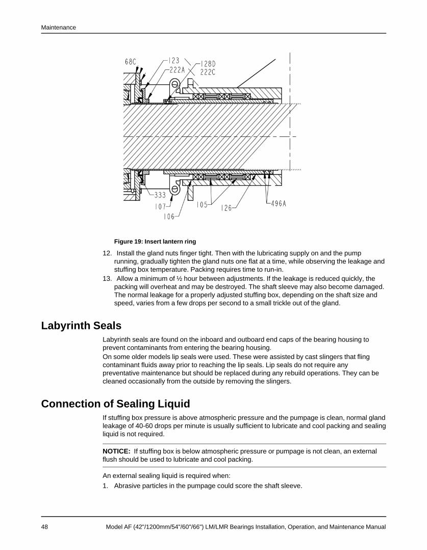
Maintenance
Figure 19: Insert lantern ring
12. Install the gland nuts finger tight. Then with the lubricating supply on and the pumprunning, gradually tighten the gland nuts one flat at a time, while observing the leakage andstuffing box temperature. Packing requires time to run-in.
13. Allow a minimum of ½ hour between adjustments. If the leakage is reduced quickly, thepacking will overheat and may be destroyed. The shaft sleeve may also become damaged.The normal leakage for a properly adjusted stuffing box, depending on the shaft size andspeed, varies from a few drops per second to a small trickle out of the gland.
Labyrinth SealsLabyrinth seals are found on the inboard and outboard end caps of the bearing housing toprevent contaminants from entering the bearing housing.On some older models lip seals were used. These were assisted by cast slingers that flingcontaminant fluids away prior to reaching the lip seals. Lip seals do not require anypreventative maintenance but should be replaced during any rebuild operations. They can becleaned occasionally from the outside by removing the slingers.
Connection of Sealing LiquidIf stuffing box pressure is above atmospheric pressure and the pumpage is clean, normal glandleakage of 40-60 drops per minute is usually sufficient to lubricate and cool packing and sealingliquid is not required.
NOTICE: If stuffing box is below atmospheric pressure or pumpage is not clean, an externalflush should be used to lubricate and cool packing.
An external sealing liquid is required when:1. Abrasive particles in the pumpage could score the shaft sleeve.
48 Model AF (42"/1200mm/54"/60"/66") LM/LMR Bearings Installation, Operation, and Maintenance Manual

Maintenance
2. Stuffing box pressure is below atmospheric pressure due to pump running when suctionsource is under vacuum. Under these conditions, packing will not be cooled and lubricatedand air will be drawn into the pump. If an outside source of clean compatible liquid isrequired, The piping should be connected to the stuffing box flush port inlet.
3. If an outside source of clean liquid is required:1. The pressure should be 15-20 psi (1.1-1.4 kg/cm2) above suction pressure.2. Under extreme temperature and pressure a pipe should also be connected to the flush
port outlet.
NOTICE: Most packing requires lubrication. Failure to lubricate packing may shorten thelife of the packing and pump.
4. An external drip pan (799G) drain is provided to carry away normal gland leakage.
1. Drip panFigure 20: External drip pan drain
Model AF (42"/1200mm/54"/60"/66") LM/LMR Bearings Installation, Operation, and Maintenance Manual 49

Disassembly
DisassemblyRemove the coupling guard
1. Remove the nut, bolt, and washers from the slotted hole in the center of the coupling guard.2. Slide the driver half of the coupling guard toward the pump.
1. Driver2. Slide to remove
3. Remove the nut, bolt, and washers from the driver half of the coupling guard.4. Remove the driver-side end plate.
1. End plate2. Coupling guard half3. Driver
5. Remove the driver half of the coupling guard:a) Slightly spread the bottom apart.b) Lift upwards.
6. Remove the remaining nut, bolt, and washers from the pump half of the coupling guard.
50 Model AF (42"/1200mm/54"/60"/66") LM/LMR Bearings Installation, Operation, and Maintenance Manual
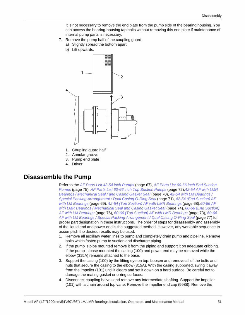
Disassembly
It is not necessary to remove the end plate from the pump side of the bearing housing. Youcan access the bearing-housing tap bolts without removing this end plate if maintenance ofinternal pump parts is necessary.
7. Remove the pump half of the coupling guard:a) Slightly spread the bottom apart.b) Lift upwards.
1. Coupling guard half2. Annular groove3. Pump end plate4. Driver
Disassemble the PumpRefer to the AF Parts List 42-54 inch Pumps (page 67), AF Parts List 60-66 inch End SuctionPumps (page 75), AF Parts List 60-66 inch Top Suction Pumps (page 72),42-54 AF with LMRBearings / Mechanical Seal / and Casing Gasket Seal (page 70), 42-54 with LM Bearings /Special Packing Arrangement / Dual Casing O-Ring Seal (page 71), 42-54 (End Suction) AFwith LM Bearings (page 69), 42-54 (Top Suction) AF with LMR Bearings (page 68),60-66 AFwith LMR Bearings / Mechanical Seal and Casing Gasket Seal (page 74), 60-66 (End Suction)AF with LM Bearings (page 76), 60-66 (Top Suction) AF with LMR Bearings (page 73), 60-66AF with LM Bearings / Special Packing Arrangement / Dual Casing O-Ring Seal (page 77) forproper part designation in these instructions. The order of steps for disassembly and assemblyof the liquid end and power end is the suggested method. However, any workable sequence toaccomplish the desired results may be used.1. Remove all auxiliary water lines to pump and completely drain pump and pipeline. Remove
bolts which fasten pump to suction and discharge piping.2. If the pump is pipe mounted remove it from the piping and support it on adequate cribbing.
If the pump is base mounted the casing (100) and power end may be removed while theelbow (315A) remains attached to the base.
3. Support the casing (100) by the lifting eye on top. Loosen and remove all of the bolts andnuts that secure the casing to the elbow (315A). With the casing supported, swing it awayfrom the impeller (101) until it clears and set it down on a hard surface. Be careful not todamage the mating gasket or o-ring surfaces.
4. Disconnect coupling halves and remove any intermediate shafting. Support the impeller(101) with a chain around top vane. Remove the impeller end cap (9988). Remove the
Model AF (42"/1200mm/54"/60"/66") LM/LMR Bearings Installation, Operation, and Maintenance Manual 51

Disassembly
screws (370C) that secure the impeller (101) and shaft washer (9985) to the shaft (122).Tapped holes in the hub of the impeller on the discharge side are provided for pulling theimpeller from the shaft. If no holes are provided, strapping or chains around the impellervanes will provide a means of pulling the impeller from the shaft. Always use the shaftcenter for the center point of a puller. Be sure to retain the impeller key (178).
NOTICE: If chains are used for pulling, place blocking between chain and impeller vanes.
5. Support bearing housing (134) and impeller end of shaft (122). Remove hex head bolts(370G) that secure bearing housing (134) to suction elbow (315A).
6. If packing is used, disassemble the gland (107), packing (106), and lantern rings (105) fromstuffing box. If mechanical seal (383) was used, please see the mechanical seal IOM forproper removal of seal.
7. With the power end properly supported. Carefully pull it from suction elbow (315A).8. The shaft sleeve (126) can be removed by loosening set screw and sliding the sleeve from
shaft (122). Be sure to retain the sleeve key (128D).
Disassemble the Power EndWARNING:Lock out driver power to prevent electric shock, accidental start-up and physical injury.
1. Lockout power supply to motor.2. Close suction and discharge valve.
WARNING:The pump may handle hazardous and/or toxic fluids. Skin and eye protection may be required.Precautions must be taken to prevent injury or environmental damage.
1. Remove piping from pump.2. Remove coupling guard and coupling (direct connect) or belt guard and belts (belt drive).3. Drain oil from bearing housing, disconnect oil circulation system, and remove pump from
sub-base.4. Wash down pump with appropriate cleaner.5. Disassemble Pump per instructions per that section. Discharge piping and impeller (101)
will be disassembled. The power end with the shaft (122) will be removed from the elbow(315A).
6. Remove cap screws (370H) fastening thrust bearing retainer (109) to bearing housing(134). Carefully pull retainer over shaft. Top suction pumps have thrust bearing (112C) atthe outboard location and the thrust bearing stationary race and (6) small springs (9890)may be jarred free. Do not damage oil seal (332).
7. Be sure overhung portion of shaft is supported.8. Remove cap screws (370F) fastening radial bearing retainer (119B) to bearing housing
(134). Carefully pull retainer away from bearing housing without damaging lip seal (333).9. Disassemble bearing halves by removing bolts and knocking out taper pins. Carefully lift
top half. The shaft (122) with bearings can be lifted from bottom half of housing10. Remove thrust end locknut (136) and lockwasher (382).
a) For top suction pumps see 42-54 (Top Suction) AF with LMR Bearings (page 68), thethrust bearing (112C), thrust bearing sleeve (196) and thrust bearing spacer (237) canbe pulled from shaft (122). Press or pull radial bearing (112) from shaft by applyingforce on inner race bearing.
52 Model AF (42"/1200mm/54"/60"/66") LM/LMR Bearings Installation, Operation, and Maintenance Manual

Disassembly
b) For end suction pumps see 42-54 (End Suction) AF with LM Bearings (page 69), pressthe entire thrust bearing stack off by pushing against stationary race of thrust bearing(112C).
11. Loosen set screws and pull oil wheel (248) off shaft.12. Push inboard radial bearing (168C) off shaft toward coupling end by applying force on
bearing inner race with a press.
Model AF (42"/1200mm/54"/60"/66") LM/LMR Bearings Installation, Operation, and Maintenance Manual 53

Reassemble the Pump
Reassemble the Pump1. Be sure shaft (122) and sleeve (126) are clean and free of all burrs. Slide shaft sleeve (126)
over shaft (122), making sure that O-rings are in place as indicated on assembly drawing.Secure sleeve with set screw (222C) and key (128D).
2. Provide adequate support for bearing housing (134) and shaft (122). Carefully slide shaftthrough stuffing box of suction elbow. Bolt bearing housing to suction elbow (315A).
3. Install shaft O-rings (496C & 496D) on shaft (122). Place the shaft key (178) in the keyway.Lubricate the O-rings as required.
4. Carefully install impeller (101) on shaft (122). With shaft washer (9985) in place, install (4)cap screws (370C) to secure the impeller to the shaft. Install impeller end cap (9988) witho-ring (496B) as required.
5. Bolt casing (100) to elbow (315A) with (6) bolts evenly spaced around bolt circle. Leavebolts loose enough to shift casing for alignment with impeller. The actual adjustment ofcasing is accomplished by turning the adjusting screws (370B) against casing flange.
6. The procedure for setting impeller clearance is described in the ALIGNMENT section ofthese instructions. When acceptable alignment has been achieved, secure the initial (6)bolts, then install the remaining bolts and tighten.
7. Before connecting the coupling halves, check direction of motor rotation. Manually turnpump shaft to insure no rubbing. Be sure the pump and gear box shafts are in alignmentaccording to the previously discussed alignment procedure.
8. Connect coupling halves and any intermediate shafting.9. Assemble discharge piping to casing.10. If packing is used, assemble gland, packing, lantern rings and sleeve into stuffing box. Do
not compress too tightly until after start-up. The packing will need to be "run-in" andadjusted for proper flow of lubricating water. If a mechanical seal is used, please see themechanical seal IOM for proper installation of seal.
11. Connect seal water and cooling lines to pump. Fill the oil lubrication system. Be surebearing housing oil is level with the center of the sight glass.
54 Model AF (42"/1200mm/54"/60"/66") LM/LMR Bearings Installation, Operation, and Maintenance Manual

Reassemble the Power End
Reassemble the Power End1. Be sure shaft is clean and free from all burrs.2. Heat inboard radial bearing (168C) in a 200°F (93°C) oil bath or by induction heater. Slide
bearing on shaft (122), butting against shaft shoulder. Position oil wheel (248) on shaft(122) and secure with set screws.
3. Heat thrust end bearings (112) & (112C) and sleeve (if used), in 200°F (93°C) oil bath. Ifthrust bearing rotation race mounts on spacer (443), install race on collar and heat collarwith bearing mounted in oil bath.a) For top suction pumps 42-54 (Top Suction) AF with LMR Bearings (page 68), slide
bearing (112), spacer (237), and sleeve into position, tight against each other andagainst shaft shoulder. After sleeve has cooled, install thrust bearing (112C).
4. When the thrust bearing is in the outboard position the stationary race will usually fit overthe lock nut and washer. This saves the trouble of trying to keep the race in positionbecause it can be set aside until retainer (109) is installed.a) For end suction pumps 42-54 (End Suction) AF with LM Bearings (page 69), slide
spacer (443) with mounted thrust bearing (112C), including stationary race, intoposition against shaft shoulder. If a spacer drive key is used, be sure it is installed.Install bearing (112) against collar.
5. Secure bearings with lockwasher (382) and locknut (136). Retighten locknut whilecomponents are cooling to keep them tight together.
6. Install (6) thrust bearings springs (9890) in thrust bearing retainer (109) or bearing housing(134) halves. Use thick grease in each hole to help hold springs until assembly.
7. Lower shaft (122) into bottom half of bearing housing (134). Be careful not to damagebearings or machined fits.
8. If springs (9890) are located in the housing, keep the shaft about 3/8" (.95cm) outboard ofnormal position so springs are not compressed.
9. Lower top half of housing into position, align with taper pins, and secure together with bolts.10. Install thrust bearing retainer. Do not damage lip seal.11. Slide thrust bearing retainer (109) and gasket (360R) onto shaft to contact bearing housing
(134). Do not damage lip seal (332). Fasten retainer to bearing housing with cap screws.
Model AF (42"/1200mm/54"/60"/66") LM/LMR Bearings Installation, Operation, and Maintenance Manual 55

Reassemble the drive / guard
Reassemble the drive / guard1. Insert the drive key (400) into the shaft (122) keyseat.2. Depending on the drive type, install the hub fasteners for a coupling or sheave to the shaft
(122).If you have a coupling halve that is interference fit, you may need to heat it before installingon the shaft (122). Drive instructions are included with the data package. Follow themanufacturer’s instructions for coupling or sheave installation.
Figure 21: Coupling reassembly
NOTICE: Depending on the drive arrangement, either V-belt or Direct Connect, followapplicable steps.
V-belt configuration3. Using a crane, lift the pump into place on the sub-base.
Be careful not to damage the pump by striking any beams or walls that may be near thepump.
4. If any shims were found under the bearing housing feet during disassembly replace them atthis time
5. Install the pump to sub-base bolts (500A) and remove the lifting straps or chains fromaround the bearing housing (134) and elbow (100).
56 Model AF (42"/1200mm/54"/60"/66") LM/LMR Bearings Installation, Operation, and Maintenance Manual

Reassemble the drive / guard
Figure 22: Pump to sub-base reassembly
6. Install V-belts and re-apply tension by adjusting the slide base away from the pump.7. Adjust and check the tension per the drive manufacturers instructions.
1. Install belts 2. Shift slide base
Figure 23: V-belt installation
8. Fasten the guard base (501) to the sub-base using screws (502). Install the guard cover(500) using screws (502).
Model AF (42"/1200mm/54"/60"/66") LM/LMR Bearings Installation, Operation, and Maintenance Manual 57

Reassemble the drive / guard
Figure 24: Guard base to sub-base reassembly
9. Check impeller alignment and re-align if necessary according to instructions for (impelleralignment).Direct connect configuration
10. Using a crane, lift the pump into place on the sub-base.Be careful not to damage the pump by striking any beams or walls that may be near thepump.
11. If any shims were found under the bearing housing feet during disassembly replace themat this time.
12. Install the pump to sub-base bolts (500A) and remove the lifting straps or chains fromaround the bearing housing (134) and elbow (100).
Figure 25: Direct drive - pump to sub-base reassembly
13. Align the gear box and pump coupling halves as described in sub-base installation section.If the motor and gear box were moved during disassembly re-align they must be re-alignedalso.
14. Wrap the coupling cover around the coupling halves and install the fasteners that hold thecoupling cover together.
58 Model AF (42"/1200mm/54"/60"/66") LM/LMR Bearings Installation, Operation, and Maintenance Manual
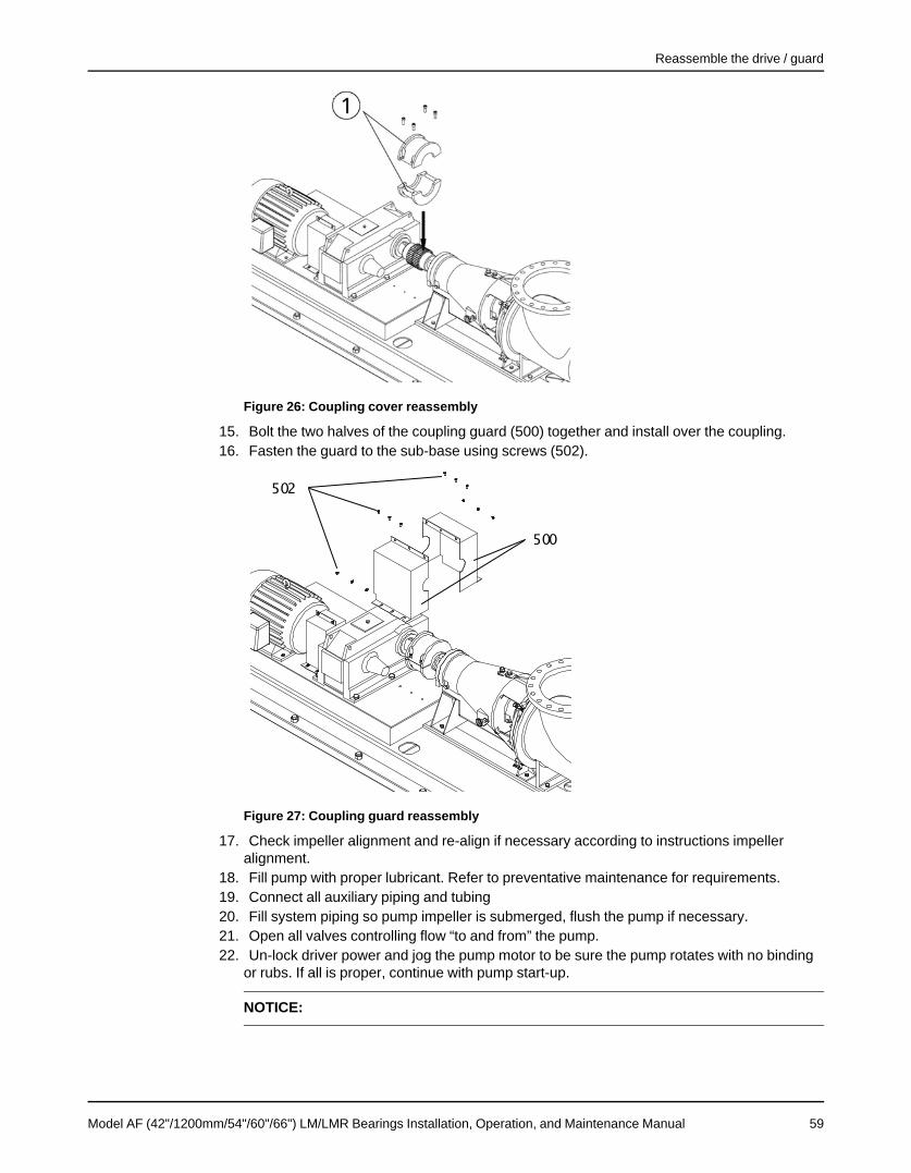
Reassemble the drive / guard
Figure 26: Coupling cover reassembly
15. Bolt the two halves of the coupling guard (500) together and install over the coupling.16. Fasten the guard to the sub-base using screws (502).
Figure 27: Coupling guard reassembly
17. Check impeller alignment and re-align if necessary according to instructions impelleralignment.
18. Fill pump with proper lubricant. Refer to preventative maintenance for requirements.19. Connect all auxiliary piping and tubing20. Fill system piping so pump impeller is submerged, flush the pump if necessary.21. Open all valves controlling flow “to and from” the pump.22. Un-lock driver power and jog the pump motor to be sure the pump rotates with no binding
or rubs. If all is proper, continue with pump start-up.
NOTICE:
Model AF (42"/1200mm/54"/60"/66") LM/LMR Bearings Installation, Operation, and Maintenance Manual 59

Inspections
InspectionsImpeller
1. Inspect impeller vanes for damage (101). Check the vane O.D. for erosion. Check the vanesurfaces, replace if grooved, worn, or eroded deeper than 3/16" (5.0 mm.) Excessiveimpeller wear may cause a reduction in performance.
2. Inspect the leading and trailing edges of the vanes for pitting, erosion or corrosion damagereplace if grooved, or worn deeper than 3/16" (5.0 mm.)
3. Inspect the root (vane attach point at hub) of each vane for cracks. Impeller vane failurecan cause unbalance in the rotating assembly that will lead to catastrophic failure of thepump.
4. Inspect the keyway and stepped bores for signs of pitting, wear or corrosion damage.5. Check the O-ring groove and bolt holes for signs of pitting or corrosion.
Shaft1. Check the shaft (122) for straightness, wear, corrosion, and radial run-out. Maximum run-
out for non-contact portions of the shaft is .002" (.05 mm) max.2. Bearing seats and seal areas must be smooth and free of scratches and grooves. Shaft
hole threads must be in good condition. Replace if necessary.
Shaft Sleeve1. The shaft sleeve (126) should be replaced if badly grooved or worn. Localized wear or
grooving greater than 3/32" (2.4 mm) deep is cause for replacement, see Fig. 50.
BearingsThe bearings (112, 112C, and 168C) should be inspected for contamination and damage. Thecondition of the bearing will provide useful information on operating conditions in the bearinghousing. Lubrication condition and residue should be noted. Bearing damage should beinvestigated to determine the cause. If cause is not normal wear, it should be corrected beforethe pump is returned to service.
NOTICE: Do not re-use bearings
Oil Seals, O-Rings, GasketsAlthough the oil seals (332, 333), O-rings (351A, 351B, 496A, 496B, 496C) and gaskets (360R,360X,) may seem OK during inspection and examination, DO NOT RE-USE SEALS whenrebuilding the pump. Replace them while pump is disassembled.
60 Model AF (42"/1200mm/54"/60"/66") LM/LMR Bearings Installation, Operation, and Maintenance Manual

Troubleshooting
TroubleshootingPump Troubleshooting
Table 6: Pump TroubleshootingSymptom Cause Remedy
Pump not primed or prime lost, Fill system piping completely soliquid level does not completely fill the impeller is submergedelbowSuction inlet clogged Remove obstructions from pump
inletImpeller clogged with foreign ma- Back flush pump or manuallyterial clean impellerSuction and /or discharge valve Open valves to remove shut-offclosed or clogged conditionWrong direction of rotation Change rotation to concur withNo liquid delivered or intermittent
direction indicated by the arrow onflowthe bearing housing
Suction piping incorrect Replace or modify suction pipingInsufficient NPSH available Increase liquid level or lower
pumpAir leak in suction line Test suction piping for leaksSpeed (rpm) too low New drive or gear box to obtain
higher pump speedExcess air entrapped in liquid Install vent in piping or eliminate
air sourceImpeller partly clogged Back flush pump or manually
clean impellerInsufficient suction head Fill system piping so the liquid
level is above the pump impellercenterline
Pump not primed or prime lost, Fill system piping completely sopump does not completely fill el- the impeller is submergedbowSuction and/or discharge valve Open valves to remove partiallyclosed or clogged blocked conditionSuction piping incorrect Replace or modify suction pipingExcessive air entrapped in liquid Install vent in piping or eliminate
air sourcePump not producing rated flow orhead Speed (rpm) too low New drive or gear box to obtain
higher pump speedIncorrect rotation Check motor wiringIncorrect impeller or impeller di- Check vane angles and/ or impel-ameter ler clearancesSystem head too high Check system curve calculations,
reduce system resistanceInstruments give erroneous read- Check and calibrate instruments,ings replace if necessaryWorn or broken impeller, bent Inspect and replace if necessaryvanesPump assembled incorrectly Compare pump assembly to in-
struction manual
Model AF (42"/1200mm/54"/60"/66") LM/LMR Bearings Installation, Operation, and Maintenance Manual 61
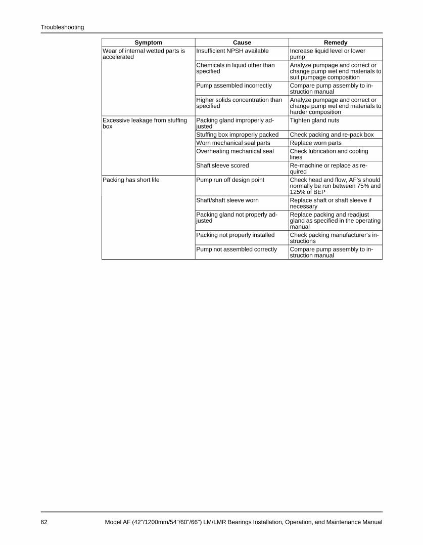
Troubleshooting
Symptom Cause RemedyWear of internal wetted parts is Insufficient NPSH available Increase liquid level or loweraccelerated pump
Chemicals in liquid other than Analyze pumpage and correct orspecified change pump wet end materials to
suit pumpage compositionPump assembled incorrectly Compare pump assembly to in-
struction manualHigher solids concentration than Analyze pumpage and correct orspecified change pump wet end materials to
harder compositionExcessive leakage from stuffing Packing gland improperly ad- Tighten gland nutsbox justed
Stuffing box improperly packed Check packing and re-pack boxWorn mechanical seal parts Replace worn partsOverheating mechanical seal Check lubrication and cooling
linesShaft sleeve scored Re-machine or replace as re-
quiredPacking has short life Pump run off design point Check head and flow, AF’s should
normally be run between 75% and125% of BEP
Shaft/shaft sleeve worn Replace shaft or shaft sleeve ifnecessary
Packing gland not properly ad- Replace packing and readjustjusted gland as specified in the operating
manualPacking not properly installed Check packing manufacturer's in-
structionsPump not assembled correctly Compare pump assembly to in-
struction manual
62 Model AF (42"/1200mm/54"/60"/66") LM/LMR Bearings Installation, Operation, and Maintenance Manual

Troubleshooting
Symptom Cause RemedyLubricant level Be sure the oil level is at center
line of sight glassImproper lubricant Check lubricant for suitabilityNot lubricated enough Increase frequency of grease lu-
bricationBroken or bent impeller vanes Check impeller dimensions and
vane layoutExcessive shaft misalignment Check shaft run-out and consult
factoryInadequate lubricant cooling Check pumpage temperature and
add oil cooling system if neces-sary
Axial thrust or radial load higher Calculate bearing life for makethan bearing rating and model bearingImproper coupling lubrication Check coupling lubrication sched-
ule in manufacturers installation,operation, maintenance manual
Coupling out of balance Check pump and drive componentvibration levels, rebalancecoupling if necessary
Suction pressure too high Check liquid levels and static suc-tion pressure
Bearings run hot and or fail on a Bearing incorrectly installed Check bearing orientation to sec-regular basis tional drawing
Impeller out of balance Check pump vibrations, if neces-sary rebalance impeller
Excessive shaft deflection Check shaft diameter, sag anddeflection, consult factory
Pump run off design point Check head and flow, AF’s shouldnormally be run between 75% and125% of BEP
Lubricant contamination Inspect oil or grease for contami-nants
Piping not properly anchored Check to see if excessive pipestrain is being transferred to pumpflanges
Pump and/or driver not secured to Check fasteners, if loose checksub-base alignment and re-tightenSpecific gravity higher than spec- Analyze pumpage and compare toified specified gravityViscosity higher than specified Analyze pumpage and compare to
specified viscosityPump assembled incorrectly Compare pump assembly to in-
struction manualPartly clogged impeller causing Back flush pump or manuallyImbalance clean impeller
Model AF (42"/1200mm/54"/60"/66") LM/LMR Bearings Installation, Operation, and Maintenance Manual 63

Troubleshooting
Symptom Cause RemedyPump is noisy or vibrates at high- Broken or bent impeller or shaft Replace as requireder than normal levels Pump foundation not rigid or sub- Tighten hold down bolts on sub-
base not completely secured base Check foundation rigidityImpeller out of balance Check impeller balanceMotor not secure Check motor fastenersImproper coupling lubrication Check coupling lubrication sched-
ule in manufacturers installation,operation, maintenance manual
Bearing incorrectly installed Check bearing orientation to sec-tional drawing
Coupling out of balance Check pump and drive componentvibration levels, rebalancecoupling if necessary
Pump operating speed too close Change speed to be +/- 20% ofto system’s natural frequency the pumps natural frequencyImpeller partly clogged Back flush pump or manually
clean impellerImpeller clearances too tight Check impeller clearances adjust
if necessaryPump assembled incorrectly Compare pump assembly to in-
struction manualPump run off design point Check head and flow, AF’s should
normally be run between 75% and125% of BEP
Excessive shaft deflection Check shaft diameter, sag anddeflection, consult factory
Worn bearings ReplaceSuction or discharge piping not Anchor per Hydraulic Instituteanchored or properly supported Strandards Manual recommenda-
tionSuction and/or discharge valve Open valves to remove partiallyclosed or clogged blocked conditionExcessive shaft misalignment Check shaft run-out and consult
factoryPump assembled incorrectly Compare pump assembly to in-
struction manualPump is cavitating, insufficient System problem, increase liquidNPSH available level or lower pump
64 Model AF (42"/1200mm/54"/60"/66") LM/LMR Bearings Installation, Operation, and Maintenance Manual
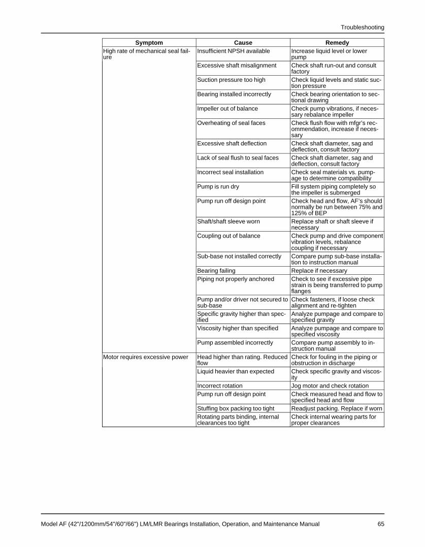
Troubleshooting
Symptom Cause RemedyHigh rate of mechanical seal fail- Insufficient NPSH available Increase liquid level or lowerure pump
Excessive shaft misalignment Check shaft run-out and consultfactory
Suction pressure too high Check liquid levels and static suc-tion pressure
Bearing installed incorrectly Check bearing orientation to sec-tional drawing
Impeller out of balance Check pump vibrations, if neces-sary rebalance impeller
Overheating of seal faces Check flush flow with mfgr’s rec-ommendation, increase if neces-sary
Excessive shaft deflection Check shaft diameter, sag anddeflection, consult factory
Lack of seal flush to seal faces Check shaft diameter, sag anddeflection, consult factory
Incorrect seal installation Check seal materials vs. pump-age to determine compatibility
Pump is run dry Fill system piping completely sothe impeller is submerged
Pump run off design point Check head and flow, AF’s shouldnormally be run between 75% and125% of BEP
Shaft/shaft sleeve worn Replace shaft or shaft sleeve ifnecessary
Coupling out of balance Check pump and drive componentvibration levels, rebalancecoupling if necessary
Sub-base not installed correctly Compare pump sub-base installa-tion to instruction manual
Bearing failing Replace if necessaryPiping not properly anchored Check to see if excessive pipe
strain is being transferred to pumpflanges
Pump and/or driver not secured to Check fasteners, if loose checksub-base alignment and re-tightenSpecific gravity higher than spec- Analyze pumpage and compare toified specified gravityViscosity higher than specified Analyze pumpage and compare to
specified viscosityPump assembled incorrectly Compare pump assembly to in-
struction manualMotor requires excessive power Head higher than rating. Reduced Check for fouling in the piping or
flow obstruction in dischargeLiquid heavier than expected Check specific gravity and viscos-
ityIncorrect rotation Jog motor and check rotationPump run off design point Check measured head and flow to
specified head and flowStuffing box packing too tight Readjust packing. Replace if wornRotating parts binding, internal Check internal wearing parts forclearances too tight proper clearances
Model AF (42"/1200mm/54"/60"/66") LM/LMR Bearings Installation, Operation, and Maintenance Manual 65

Spare Parts
Spare PartsWhen ordering spare parts, always state Goulds Serial No., and indicate part name and itemnumber from relevant sectional drawing. It is imperative for service reliability to have a sufficientstock of readily available spares.
Recommended Spare PartsSuggested Spare PartsElbow and or Casing (100, 315A) Outboard Oil Seal (332)Impeller (101) Inboard Oil Seal (333)Gaskets (360R, 360X) Shaft Sleeve (126) (Optional)O-Rings (351A, 351B, 496B, 496C, 496D) Sleeve O-rings (496A) (Optional)Shaft (122) Stuffing Box Bushing (473) (Optional)Inboard Radial Bearing (168C) Lantern Ring (105) (Optional)Outboard Thrust Bearings (112, 112C) Stuffing Box Packing (106) (Optional)Bearing Lockwasher (382) Packing Gland (107) (Optional)Bearing Locknut (136)
66 Model AF (42"/1200mm/54"/60"/66") LM/LMR Bearings Installation, Operation, and Maintenance Manual
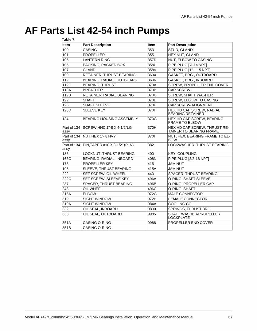
AF Parts List 42-54 inch Pumps
AF Parts List 42-54 inch PumpsTable 7:Item Part Description Item Part Description100 CASING 353 STUD, GLAND101 PROPELLER 355 HEX NUT, GLAND105 LANTERN RING 357D NUT, ELBOW TO CASING106 PACKING, PACKED BOX 358U PIPE PLUG [½-14 NPT]107 GLAND 358V PIPE PLUG [1”-11.5 NPT]109 RETAINER, THRUST BEARING 360X GASKET, BRG., OUTBOARD112 BEARING, RADIAL, OUTBOARD 360R GASKET, BRG., INBOARD112C BEARING, THRUST 370A SCREW, PROPELLER END COVER113A BREATHER 370B CAP SCREW119B RETAINER, RADIAL BEARING 370C SCREW, SHAFT WASHER122 SHAFT 370D SCREW, ELBOW TO CASING126 SHAFT SLEEVE 370E CAP SCREW-ALIGNMENT128D SLEEVE KEY 370F HEX HD CAP SCREW, RADIAL
BEARING RETAINER134 BEARING HOUSING ASSEMBLY 370G HEX HD CAP SCREW, BEARING
FRAME TO ELBOWPart of 134 SCREW,HHC 1"-8 X 4-1/2"LG 370H HEX HD CAP SCREW, THRUST RE-assy TAINER TO BEARING FRAMEPart of 134 NUT,HEX 1"- 8 HVY 370I NUT, HEX, BEARING FRAME TO EL-assy BOWPart of 134 PIN,TAPER #10 X 3-1/2" (PLN) 382 LOCKWASHER, THRUST BEARINGassy136 LOCKNUT, THRUST BEARING 400 KEY, COUPLING168C BEARING, RADIAL, INBOARD 408N PIPE PLUG [3/8-18 NPT]178 PROPELLER KEY 415 JAM NUT196 SLEEVE, THRUST BEARING 415A JAM NUT222 SET SCREW, OIL WHEEL 443 SPACER, THRUST BEARING222C SET SCREW, SLEEVE KEY 496A O-RING, SHAFT SLEEVE237 SPACER, THRUST BEARING 496B O-RING, PROPELLER CAP248 OIL WHEEL 496C O-RING, SHAFT315A ELBOW 972G MALE CONNECTOR319 SIGHT WINDOW 972H FEMALE CONNECTOR319A SIGHT WINDOW 984A COOLING COIL332 OIL SEAL, INBOARD 9890 SPRINGS, THRUST BRG333 OIL SEAL, OUTBOARD 9985 SHAFT WASHER/PROPELLER
LOCKPLATE351A CASING O-RING 9988 PROPELLER END COVER351B CASING O-RING
Model AF (42"/1200mm/54"/60"/66") LM/LMR Bearings Installation, Operation, and Maintenance Manual 67
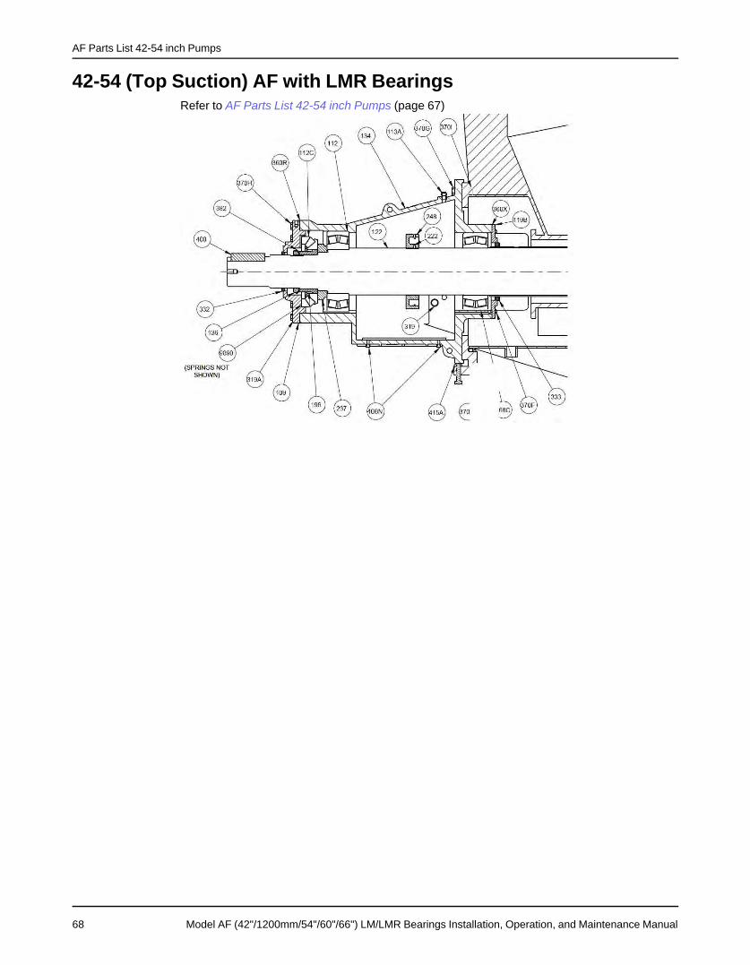
AF Parts List 42-54 inch Pumps
42-54 (Top Suction) AF with LMR BearingsRefer to AF Parts List 42-54 inch Pumps (page 67)
68 Model AF (42"/1200mm/54"/60"/66") LM/LMR Bearings Installation, Operation, and Maintenance Manual

AF Parts List 42-54 inch Pumps
42-54 (End Suction) AF with LM BearingsRefer to 42-54 (End Suction) AF with LM Bearings (page 69)
Model AF (42"/1200mm/54"/60"/66") LM/LMR Bearings Installation, Operation, and Maintenance Manual 69
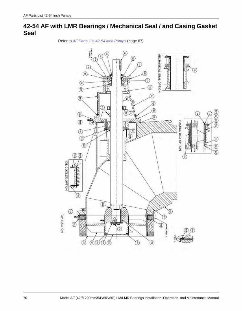
AF Parts List 42-54 inch Pumps
42-54 AF with LMR Bearings / Mechanical Seal / and Casing GasketSeal
Refer to AF Parts List 42-54 inch Pumps (page 67)
70 Model AF (42"/1200mm/54"/60"/66") LM/LMR Bearings Installation, Operation, and Maintenance Manual

AF Parts List 42-54 inch Pumps
42-54 with LM Bearings / Special Packing Arrangement / DualCasing O-Ring Seal
Refer to AF Parts List 42-54 inch Pumps (page 67)
Model AF (42"/1200mm/54"/60"/66") LM/LMR Bearings Installation, Operation, and Maintenance Manual 71

AF Parts List 60-66 inch Top Suction Pumps
AF Parts List 60-66 inch Top Suction PumpsItem Part Description Item Part Description100 CASING 357D HEX NUT, ELBOW TO CASING101 PROPELLER 358U PIPE PLUG [1/2-14 NPT] (NOT
SHOWN)105 LANTERN RING 358V PIPE PLUG [1"-11.5 NPT] (NOT
SHOWN)106 PACKING, PACKED BOX 360R GASKET, BRG., INBOARD107 GLAND 360X GASKET, BRG., OUTBOARD109 RETAINER, THRUST BEARING 370A STUD, PROPELLER END COVER112 BEARING, RADIAL, OUTBOARD 370B CAP SCREW - SUCTION ALIGN-
MENT112C BEARING, THRUST 370C CAP SCREW, SHAFT WASHER113A BREATHER 370D STUD, ELBOW TO CASING119B RETAINER, RADIAL BEARING 370E CAP SCREW-ALIGNMENT122 SHAFT 370F CAP SCREW, RADIAL BEARING RE-
TAINER126 SHAFT, SLEEVE 370G CAP SCREW, BEARING FRAME TO
ELBOW128D SLEEVE KEY 370H CAP SCREW, THRUST RETAINER
TO BEARING FRAME134 BEARING FRAME ASSEMBLY 370I HEX NUT, BEARING FRAME TO EL-
BOW136 LOCKNUT, THRUST BEARING 382 LOCKNUT CLIP168C BEARING, RADIAL INBOARD 383 MECHANICAL SEAL178 PROPELLER KEY 400 KEY, COUPLING196 SLEEVE, THRUST BEARING 408A PIPE PLUG (1"-11.5 NPT)222 SET SCREW, OIL WHEEL 408H PLUG - PROPELLER CAP222C SET SCREW, SLEEVE KEY 415 JAM NUT - SUCTION ALIGNMENT248 OIL WHEEL 415A JAM NUT - ALIGNMENT315A ELBOW 443 SPACER, BEARING319 SIGHT WINDOW 467A HEX BUSHING - BREATHER319A SIGHT WINDOW 473 THROAT BUSHING332 OIL SEAL, OUTBOARD 494 FRAME COOLER ASSEMBLY333 OIL SEAL, INBOARD 496A O-RING, SHAFT SLEEVE351A CASING 0-RING 496B O-RING. PROPELLER END COVER351B CASING 0-RING 496C O-RING, SHAFT TO PROPELLER353 STUD, GLAND 9890 SPRINGS, THRUST BEARING355 HEX NUT, GLAND 9985 SHAFT WASHER / PROPELLER
LOCKPLATE9988 PROPELLER END COVER
72 Model AF (42"/1200mm/54"/60"/66") LM/LMR Bearings Installation, Operation, and Maintenance Manual

AF Parts List 60-66 inch Top Suction Pumps
60-66 (Top Suction) AF with LMR BearingsRefer to AF Parts List 60-66 inch Top Suction Pumps (page 72)
Model AF (42"/1200mm/54"/60"/66") LM/LMR Bearings Installation, Operation, and Maintenance Manual 73
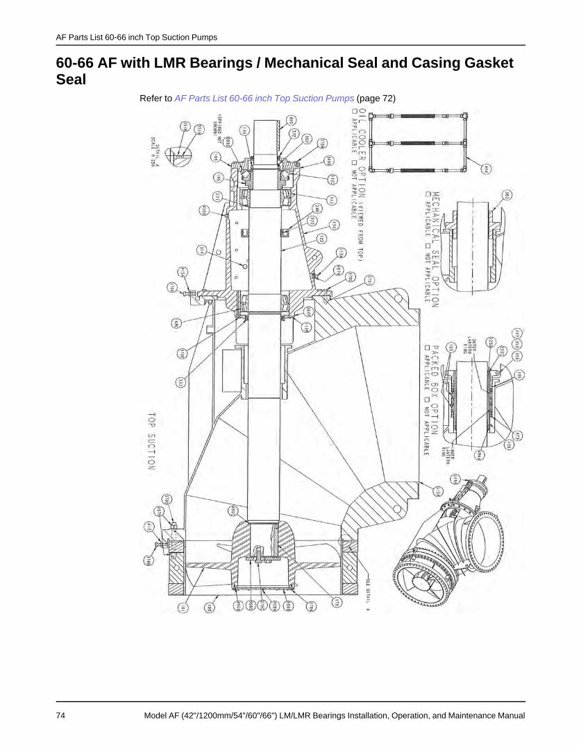
AF Parts List 60-66 inch Top Suction Pumps
60-66 AF with LMR Bearings / Mechanical Seal and Casing GasketSeal
Refer to AF Parts List 60-66 inch Top Suction Pumps (page 72)
74 Model AF (42"/1200mm/54"/60"/66") LM/LMR Bearings Installation, Operation, and Maintenance Manual
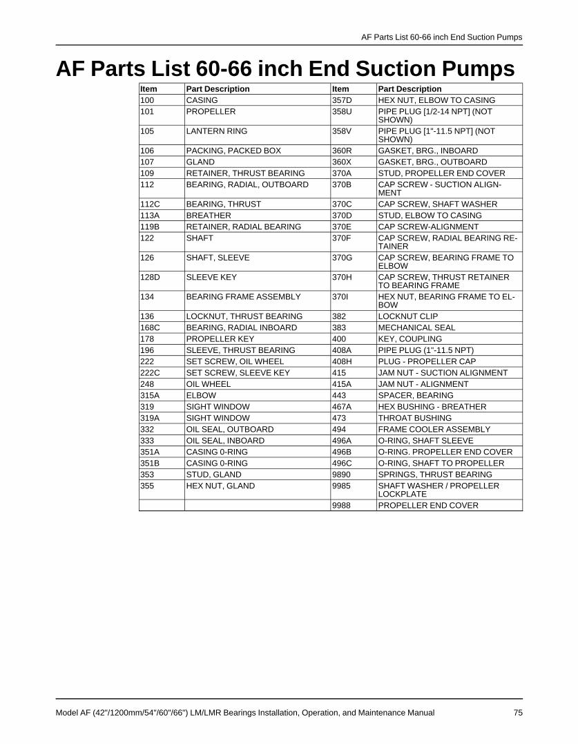
AF Parts List 60-66 inch End Suction Pumps
AF Parts List 60-66 inch End Suction PumpsItem Part Description Item Part Description100 CASING 357D HEX NUT, ELBOW TO CASING101 PROPELLER 358U PIPE PLUG [1/2-14 NPT] (NOT
SHOWN)105 LANTERN RING 358V PIPE PLUG [1"-11.5 NPT] (NOT
SHOWN)106 PACKING, PACKED BOX 360R GASKET, BRG., INBOARD107 GLAND 360X GASKET, BRG., OUTBOARD109 RETAINER, THRUST BEARING 370A STUD, PROPELLER END COVER112 BEARING, RADIAL, OUTBOARD 370B CAP SCREW - SUCTION ALIGN-
MENT112C BEARING, THRUST 370C CAP SCREW, SHAFT WASHER113A BREATHER 370D STUD, ELBOW TO CASING119B RETAINER, RADIAL BEARING 370E CAP SCREW-ALIGNMENT122 SHAFT 370F CAP SCREW, RADIAL BEARING RE-
TAINER126 SHAFT, SLEEVE 370G CAP SCREW, BEARING FRAME TO
ELBOW128D SLEEVE KEY 370H CAP SCREW, THRUST RETAINER
TO BEARING FRAME134 BEARING FRAME ASSEMBLY 370I HEX NUT, BEARING FRAME TO EL-
BOW136 LOCKNUT, THRUST BEARING 382 LOCKNUT CLIP168C BEARING, RADIAL INBOARD 383 MECHANICAL SEAL178 PROPELLER KEY 400 KEY, COUPLING196 SLEEVE, THRUST BEARING 408A PIPE PLUG (1"-11.5 NPT)222 SET SCREW, OIL WHEEL 408H PLUG - PROPELLER CAP222C SET SCREW, SLEEVE KEY 415 JAM NUT - SUCTION ALIGNMENT248 OIL WHEEL 415A JAM NUT - ALIGNMENT315A ELBOW 443 SPACER, BEARING319 SIGHT WINDOW 467A HEX BUSHING - BREATHER319A SIGHT WINDOW 473 THROAT BUSHING332 OIL SEAL, OUTBOARD 494 FRAME COOLER ASSEMBLY333 OIL SEAL, INBOARD 496A O-RING, SHAFT SLEEVE351A CASING 0-RING 496B O-RING. PROPELLER END COVER351B CASING 0-RING 496C O-RING, SHAFT TO PROPELLER353 STUD, GLAND 9890 SPRINGS, THRUST BEARING355 HEX NUT, GLAND 9985 SHAFT WASHER / PROPELLER
LOCKPLATE9988 PROPELLER END COVER
Model AF (42"/1200mm/54"/60"/66") LM/LMR Bearings Installation, Operation, and Maintenance Manual 75

AF Parts List 60-66 inch End Suction Pumps
60-66 (End Suction) AF with LM BearingsRefer to AF Parts List 60-66 inch End Suction Pumps (page 75)
76 Model AF (42"/1200mm/54"/60"/66") LM/LMR Bearings Installation, Operation, and Maintenance Manual

AF Parts List 60-66 inch End Suction Pumps
60-66 AF with LM Bearings / Special Packing Arrangement / DualCasing O-Ring Seal
Refer to AF Parts List 60-66 inch End Suction Pumps (page 75)
Model AF (42"/1200mm/54"/60"/66") LM/LMR Bearings Installation, Operation, and Maintenance Manual 77
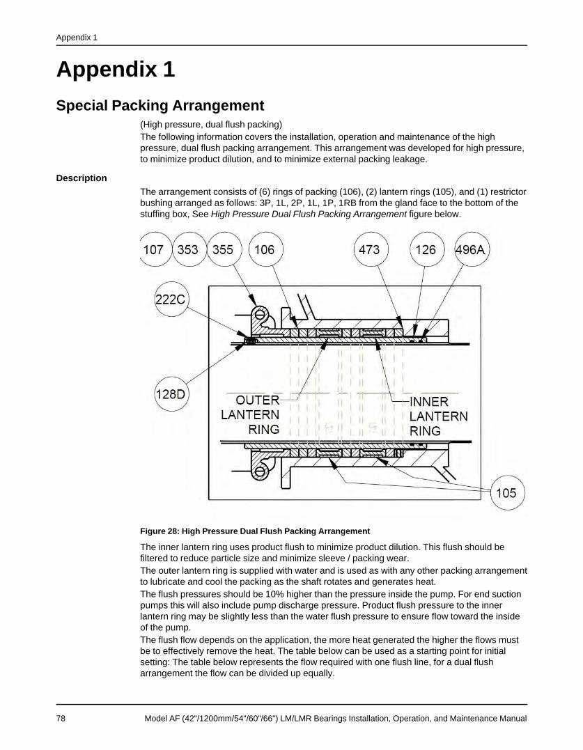
Appendix 1
Appendix 1Special Packing Arrangement
(High pressure, dual flush packing)The following information covers the installation, operation and maintenance of the highpressure, dual flush packing arrangement. This arrangement was developed for high pressure,to minimize product dilution, and to minimize external packing leakage.
DescriptionThe arrangement consists of (6) rings of packing (106), (2) lantern rings (105), and (1) restrictorbushing arranged as follows: 3P, 1L, 2P, 1L, 1P, 1RB from the gland face to the bottom of thestuffing box, See High Pressure Dual Flush Packing Arrangement figure below.
Figure 28: High Pressure Dual Flush Packing Arrangement
The inner lantern ring uses product flush to minimize product dilution. This flush should befiltered to reduce particle size and minimize sleeve / packing wear.The outer lantern ring is supplied with water and is used as with any other packing arrangementto lubricate and cool the packing as the shaft rotates and generates heat.The flush pressures should be 10% higher than the pressure inside the pump. For end suctionpumps this will also include pump discharge pressure. Product flush pressure to the innerlantern ring may be slightly less than the water flush pressure to ensure flow toward the insideof the pump.The flush flow depends on the application, the more heat generated the higher the flows mustbe to effectively remove the heat. The table below can be used as a starting point for initialsetting: The table below represents the flow required with one flush line, for a dual flusharrangement the flow can be divided up equally.
78 Model AF (42"/1200mm/54"/60"/66") LM/LMR Bearings Installation, Operation, and Maintenance Manual
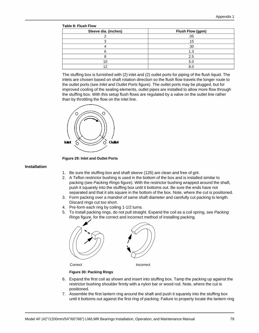
Appendix 1
Table 8: Flush FlowSleeve dia. (inches) Flush Flow (gpm)
2 .053 .154 .306 1.38 2.510 5.012 8.0
The stuffing box is furnished with (2) inlet and (2) outlet ports for piping of the flush liquid. Theinlets are chosen based on shaft rotation direction so the flush flow travels the longer route tothe outlet ports (see Inlet and Outlet Ports figure). The outlet ports may be plugged, but forimproved cooling of the sealing elements, outlet pipes are installed to allow more flow throughthe stuffing box. With this setup flush flows are regulated by a valve on the outlet line ratherthan by throttling the flow on the inlet line.
Figure 29: Inlet and Outlet Ports
Installation1. Be sure the stuffing box and shaft sleeve (126) are clean and free of grit.2. A Teflon restrictor bushing is used in the bottom of the box and is installed similar to
packing (see Packing Rings figure). With the restrictor bushing wrapped around the shaft,push it squarely into the stuffing box until it bottoms out. Be sure the ends have notseparated and that it sits square in the bottom of the box. Note, where the cut is positioned.
3. Form packing over a mandrel of same shaft diameter and carefully cut packing to length.Discard rings cut too short.
4. Pre-form each ring by coiling 1-1/2 turns.5. To install packing rings, do not pull straight. Expand the coil as a coil spring, see Packing
Rings figure, for the correct and incorrect method of installing packing.
Correct Incorrect
Figure 30: Packing Rings
6. Expand the first coil as shown and insert into stuffing box. Tamp the packing up against therestrictor bushing shoulder firmly with a nylon bar or wood rod. Note, where the cut ispositioned.
7. Assemble the first lantern ring around the shaft and push it squarely into the stuffing boxuntil it bottoms out against the first ring of packing. Failure to property locate the lantern ring
Model AF (42"/1200mm/54"/60"/66") LM/LMR Bearings Installation, Operation, and Maintenance Manual 79

Appendix 1
with respect to the flush ports will result in insufficient packing lubrication. Packing andshaft sleeve damage may result.
8. Install the second and third coil as required by the sectional drawing, staggering the cuts90° to 120°.
9. Assemble the second lantern ring around the shaft and push it squarely into the stuffingbox until it bottoms out on the third ring of packing. Failure to property locate the lanternring with respect to the flush ports will result in insufficient packing lubrication. Packing andshaft sleeve damage may result.
10. Install the third, fourth and fifth packing ring as required by the sectional drawing,staggering the cuts 90° to 120°.
11. After all packing and lantern rings have been properly installed, insert gland into stuffingbox. Tighten gland nuts finger tight only. The shaft should turn freely.
12. Turn lubricant supply on, start pump, and adjust the gland as described in the operationsection that follows.
13. Periodic maintenance is absolutely required for all packed pumps. Normal shaft run-outshould be under .005" to avoid pounding of stuffing box packing. With excessive shaft run-out, shaft straightening or replacement is necessary.
Gland AdjustmentAdjust the stuffing box if packing is used. When the pump is first started, there should beconsiderable leakage by the gland to cool the packing. Gradually tighten the gland nuts on flatat a time while observing the leakage and stuffing box temperature. Packing requires time to“run-in” and extra coolant (leakage) while it is being “run-in”. If the leakage is reduced tooquickly, the packing will overheat and may be destroyed. The shaft sleeve may also bedamaged.
LeakageNormal leakage for a properly adjusted box, depending on shaft size and speed, varies from afew drops a second to a small trickle out of the gland.
80 Model AF (42"/1200mm/54"/60"/66") LM/LMR Bearings Installation, Operation, and Maintenance Manual


Visit our website for the latest version of thisdocument and more information:
Goulds Pumps240 Fall StreetSeneca Falls, NY 13148USATel. 1-800-446-8537Fax (315) 568-2418
Form en-US.2015-04.IOM.IAF.4266© 2015 ITT CorporationThe original instruction is in English. All non-English instructions are translations of the original instruction.


![USTA TrafficAnalysisBriefing V7 0 20150530 FINAL[1] · PDF file1."Executive"Summary" ... In2014thethreemajorGulfcarriers" –"Emirates,"Qatar"Airways"and"Etihad" Airways"–"carried"some"4.3"million"passengers"intoandout"of"the](https://static.fdocuments.net/doc/165x107/5aa125967f8b9a46238b5bf2/usta-trafficanalysisbriefing-v7-0-20150530-final1-in2014thethreemajorgulfcarriers.jpg)