INSTALLATION& OWNER’ S MANUAL
35
WIRE CONTROLLER OF AIR CONDITIONER MODEL: KJR-120C/TF-E(12V) KJR-120C/TF-G(12V) KJR-120C/TF-I(5V) KJR-120C/TF-H(12V) KJR-120C/TF-J(5V) Thank you very much for purchasing our product. Before using your unit, please read this manual carefully and keep it for future reference. INSTALLATION& OWNER’ S MANUAL
Transcript of INSTALLATION& OWNER’ S MANUAL

WIRE CONTROLLER OF AIR CONDITIONER
MODEL: KJR-120C/TF-E(12V) KJR-120C/TF-G(12V) KJR-120C/TF-I(5V) KJR-120C/TF-H(12V) KJR-120C/TF-J(5V)
Thank you very much for purchasing our product.
Before using your unit, please read this manual carefully and keep it for future reference.
INSTALLATION&OWNER’ S MANUAL

● This manual gives detailed description of the precautions that should be brought to your attention during operation. ● In order to ensure correct service of the wired controller please read this manual carefully before using the unit. ● For convenience of future reference, keep this manual after reading it.

CONTENTS
1. SAFETY PRECAUTIONS......................................................................... 1
2. INSTALLATION ACCESSORY.................................................................. 2
3. INSTALLATION METHOD.........................................................................4
4. SPECIFICATION...................................................................................... 10
5. FEATURE AND FUNCTION OF THE WIRED CONTROLLER................ 11
6. NAME ON THE LCD OF THE WIRE CONTROLLER............................ 12
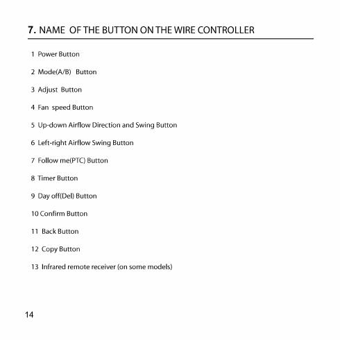
7. NAME OF BUTTON ON THE WIRE CONTROLLER............................... 13
8. PREPARATORY OPERATION..................................................................15
9. OPERATION..............................................................................................16
10. TIMER FUNCTIONS................................................................................21
11. WEEKLY TIMER......................................................................................24
12. FAULT ALARM HANDING.......................................................................31
13.TECHNICAL INDICATION AND REQUIREMENT ...................................31

1
g
g
WARNING
NOTE
1
2
3
4
1.

2
2. INSTALLATION ACCESSORY
Select the installation location
Preparation before installation
Prepare the following assemblies on the site.
1
2
3
4
5
3
2
M4X20 (For Mounting on the Wall)
M4X25 (For Mounting on switch box)
1
2
1
6
7
3
2
1
No. Name Qty. Remarks
Wire controller
For Mounting on the Wall
Switch box
Wiring Tube(Insulating Sleeve and Tightening Screw)
Qty.(embeded into wall)
Plastic screw bars
Wall plugs
For fixing on switch box
No. Name Remarks Specification
(only for reference)
1
1
1
Optional

3
2. INSTALLATION ACCESSORY

4
3. INSTALLATION METHOD
2.Wiring Principle Sketch:
red black yellow brown
red black yellow brown
Insert of the mainboard CN40
Wire controller Indoor unit mainboard 4-Core Shield Cable, the length is decided by installation
120 18.5
46
62

3. INSTALLATION METHOD
5
4-core shielding wire
3.Wiring figure
4.Remove the upper part of wire controller
Slots

6
3. INSTALLATION METHOD
Switch box
Back plate
4. Fasten the back plate of the wire controller

7
3. INSTALLATION METHOD

3. INSTALLATION METHOD
8
6. WiringTop side wire outlet
Left side wire outlet
Right side wire outlet
Bottom side wire outlet
Cutting place of top side wire outlet
Cutting place of left side wire outlet
Cutting place of right side wire outlet
A. For exposed mounting, four outletting positions. There are three need cutting.
Diameter of wall hole:Φ20mm
Embedded switch box wiring
B.Shielded wiring
Wiring hole
Wiring through the wall
Wall hole and wiring hole
Putty
Putty
Putty Trap
Trap Trap
CAUTION
Avoid the water enter into the wired remote controller, use trap and putty to seal the connectors of wires during wiring installation. (Fig.3-10) When under installation, reserve certain length of the connecting wire for convenient to take down the wired remote controller while during maintenance.

9
3. INSTALLATION METHOD
7.Reattach the upper part of the wire controller
After adjusting the upper case and then buckle the upper case; avoid clamping the wiring during installation. ( 1)

4. SPECIFICATION
10

11
5. FEATURE AND FUNCTION OF THE WIRED CONTROLLER
Lifting panel

6.
12

7.
13
7.
14

8.
Set the current day and time
15

To start/stop operation
To set the operation mode
16
6
Remote signal receiving function
The wired remote controller can be a remote signal receiving device, you can use the wireless remote controller to control the air-conditioner through the wired remote controller when the system have been powered on.

Room temperature sensor selection
17

Child lock function
18
PTC function (on some models)
°C & °F scale selection (on some models)

Faceplate function (on some models)
,
Left-right airflow swing (on some models)
19

Up-Down airflow direction and swing (on some models)
and “-”
20

21
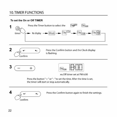
To set the On or Off TIMER
1
2
3
4
22

To set the On and Off TIMER
1
2
3
4
5
23

Weekly timer setting 1
2 Day of the week setting
Time scale setting3
24

25
4
Time setting
5
Operation mode setting
6

26
7
8
9

WEEKLY timer operation
To set the DAY OFF (for a holiday)
During the weekly timer, press the Confirm button to set the day.
1
Press the button “ + ” and “ - ” to select the day to set the DAY OFF.
2
27

3
5
: 。
4
Copy out the setting in one day into the other day.
1
2
28

3
4
5
6
7
8
29

30
Delete the time scale in one day.
1
2
3

31