INSTALLATION SUNLINE MAGNUM™ MANUAL GAS/ELECTRIC …
68
INSTALLATION MANUAL CAUTION: READ ALL SAFETY GUIDES BEFORE YOU BEGIN TO INSTALL YOUR UNIT. SAVE THIS MANUAL SUNLINE MAGNUM™ GAS/ELECTRIC SINGLE PACKAGE AIR CONDITIONERS MODELS: DJ180, 210, 240 & 300 284809-YIM-D-1008 CONTENTS GENERAL . . . . . . . . . . . . . . . . . . . . . . . . . . . . . . . . . . . .4 SAFETY CONSIDERATIONS . . . . . . . . . . . . . . . . . . . . .4 INSPECTION . . . . . . . . . . . . . . . . . . . . . . . . . . . . . . . . . .4 REFERENCE . . . . . . . . . . . . . . . . . . . . . . . . . . . . . . . . . .4 RENEWAL PARTS . . . . . . . . . . . . . . . . . . . . . . . . . . . . .5 APPROVALS . . . . . . . . . . . . . . . . . . . . . . . . . . . . . . . . . .5 PRODUCT NOMENCLATURE . . . . . . . . . . . . . . . . . . . .6 INSTALLATION . . . . . . . . . . . . . . . . . . . . . . . . . . . . . . . .7 OPERATION . . . . . . . . . . . . . . . . . . . . . . . . . . . . . . . . .45 START-UP (COOLING) . . . . . . . . . . . . . . . . . . . . . . . . .53 START-UP (GAS HEAT) . . . . . . . . . . . . . . . . . . . . . . . .53 TROUBLESHOOTING . . . . . . . . . . . . . . . . . . . . . . . . . .56 See the following page for a complete Table of Contents. NOTES, CAUTIONS AND WARNINGS The installer should pay particular attention to the words: NOTE, CAUTION, and WARNING . Notes are intended to clarify or make the installation easier. Cautions are given to prevent equipment damage. Warnings are given to alert installer that personal injury and/or equipment dam- age may result if installation procedure is not handled properly.
Transcript of INSTALLATION SUNLINE MAGNUM™ MANUAL GAS/ELECTRIC …

INSTALLATIONMANUAL
CAUTION: READ ALL SAFETY GUIDES BEFORE YOU BEGIN TO INSTALL YOUR UNIT.
SAVE THIS MANUAL
SUNLINE MAGNUM™GAS/ELECTRIC SINGLE PACKAGE
AIR CONDITIONERS
MODELS: DJ180, 210, 240 & 300
284809-YIM-D-1008
CONTENTSGENERAL . . . . . . . . . . . . . . . . . . . . . . . . . . . . . . . . . . . .4SAFETY CONSIDERATIONS . . . . . . . . . . . . . . . . . . . . .4INSPECTION . . . . . . . . . . . . . . . . . . . . . . . . . . . . . . . . . .4REFERENCE . . . . . . . . . . . . . . . . . . . . . . . . . . . . . . . . . .4RENEWAL PARTS . . . . . . . . . . . . . . . . . . . . . . . . . . . . .5APPROVALS . . . . . . . . . . . . . . . . . . . . . . . . . . . . . . . . . .5PRODUCT NOMENCLATURE . . . . . . . . . . . . . . . . . . . .6INSTALLATION . . . . . . . . . . . . . . . . . . . . . . . . . . . . . . . .7OPERATION . . . . . . . . . . . . . . . . . . . . . . . . . . . . . . . . .45START-UP (COOLING) . . . . . . . . . . . . . . . . . . . . . . . . .53START-UP (GAS HEAT) . . . . . . . . . . . . . . . . . . . . . . . .53TROUBLESHOOTING . . . . . . . . . . . . . . . . . . . . . . . . . .56
See the following page for a complete Table of Contents.
NOTES, CAUTIONS AND WARNINGS
The installer should pay particular attention to the words:NOTE, CAUTION, and WARNING. Notes are intended toclarify or make the installation easier. Cautions are givento prevent equipment damage. Warnings are given toalert installer that personal injury and/or equipment dam-age may result if installation procedure is not handledproperly.

284809-YIM-D-1008
2 Johnson Controls Unitary Products
TABLE OF CONTENTSGENERAL . . . . . . . . . . . . . . . . . . . . . . . . . . . . . . . . . . . . . . . . 4SAFETY CONSIDERATIONS . . . . . . . . . . . . . . . . . . . . . . . . . 4INSPECTION . . . . . . . . . . . . . . . . . . . . . . . . . . . . . . . . . . . . . . 4REFERENCE . . . . . . . . . . . . . . . . . . . . . . . . . . . . . . . . . . . . . . 4RENEWAL PARTS . . . . . . . . . . . . . . . . . . . . . . . . . . . . . . . . . 5APPROVALS . . . . . . . . . . . . . . . . . . . . . . . . . . . . . . . . . . . . . . 5PRODUCT NOMENCLATURE . . . . . . . . . . . . . . . . . . . . . . . . 6INSTALLATION . . . . . . . . . . . . . . . . . . . . . . . . . . . . . . . . . . . . 7
INSTALLATION SAFETY INFORMATION: . . . . . . . . . . . . . . 7LIMITATIONS . . . . . . . . . . . . . . . . . . . . . . . . . . . . . . . . . . . . 7LOCATION . . . . . . . . . . . . . . . . . . . . . . . . . . . . . . . . . . . . . . 8RIGGING AND HANDLING. . . . . . . . . . . . . . . . . . . . . . . . . . 9CLEARANCES . . . . . . . . . . . . . . . . . . . . . . . . . . . . . . . . . . . 9DUCTWORK . . . . . . . . . . . . . . . . . . . . . . . . . . . . . . . . . . . . 10FIXED OUTDOOR AIR INTAKE DAMPER . . . . . . . . . . . . . 10CONDENSATE DRAIN . . . . . . . . . . . . . . . . . . . . . . . . . . . . 11COMPRESSORS . . . . . . . . . . . . . . . . . . . . . . . . . . . . . . . . 11FILTERS . . . . . . . . . . . . . . . . . . . . . . . . . . . . . . . . . . . . . . . 11SERVICE ACCESS . . . . . . . . . . . . . . . . . . . . . . . . . . . . . . . 11THERMOSTAT . . . . . . . . . . . . . . . . . . . . . . . . . . . . . . . . . . 13SPACE SENSOR . . . . . . . . . . . . . . . . . . . . . . . . . . . . . . . . 13POWER AND CONTROL WIRING . . . . . . . . . . . . . . . . . . . 13OPTIONAL ELECTRIC HEAT . . . . . . . . . . . . . . . . . . . . . . . 13OPTIONAL GAS HEAT . . . . . . . . . . . . . . . . . . . . . . . . . . . . 14GAS PIPING . . . . . . . . . . . . . . . . . . . . . . . . . . . . . . . . . . . . 14GAS CONNECTION . . . . . . . . . . . . . . . . . . . . . . . . . . . . . . 15L.P. UNITS, TANKS AND PIPING. . . . . . . . . . . . . . . . . . . . 16VENT AND COMBUSTION AIR HOODS . . . . . . . . . . . . . . 16
OPTIONAL ECONOMIZER/MOTORIZED DAMPER RAIN HOOD . . . . . . . . . . . . . . . . . . . . . . . . . . . . . . . . . . 17
OPTIONAL POWER EXHAUST/BAROMETRIC RELIEF DAMPER RAIN HOOD . . . . . . . . . . . . . . . . . . . 17
OPTIONAL ECONOMIZER AND POWER EXHAUST DAMPER SET POINT ADJUSTMENTS AND INFORMATION. . . . . . . . . . . . . . . . . . . . . . . . . . . . . . . . 17
MINIMUM POSITION ADJUSTMENT . . . . . . . . . . . . . . . 17ENTHALPY SET POINT ADJUSTMENT . . . . . . . . . . . . . 17POWER EXHAUST DAMPER SETPOINT. . . . . . . . . . . . 17INDOOR AIR QUALITY AQ . . . . . . . . . . . . . . . . . . . . . . . 17
OPTIONAL BAS-READY ECONOMIZER POWER EXHAUST DAMPER SET POINT ADJUSTMENT. . . . . . . 18
OPTIONAL VARIABLE AIR VOLUME (VAV) . . . . . . . . . . . 18DUCT STATIC PRESSURE TRANSDUCER . . . . . . . . . . 18VAV CONTROL BOARD . . . . . . . . . . . . . . . . . . . . . . . . . 18FACTORY-INSTALLED VFD . . . . . . . . . . . . . . . . . . . . . . 19MANUAL BYPASS . . . . . . . . . . . . . . . . . . . . . . . . . . . . . . 19BAS-READY VFD. . . . . . . . . . . . . . . . . . . . . . . . . . . . . . . 20'VFD-READY' FOR CUSTOMER-INSTALLATION. . . . . . 20
OPTIONAL HOT GAS BYPASS (HGBP) . . . . . . . . . . . . . . 21CFM, STATIC PRESSURE, AND POWER - ALTITUDE AND TEMPERATURE CORRECTIONS . . . . . . . . . . . . . . 32
PHASING. . . . . . . . . . . . . . . . . . . . . . . . . . . . . . . . . . . . . . . 44CHECKING SUPPLY AIR CFM. . . . . . . . . . . . . . . . . . . . . . 44AIR BALANCE. . . . . . . . . . . . . . . . . . . . . . . . . . . . . . . . . . . 44
OPERATION . . . . . . . . . . . . . . . . . . . . . . . . . . . . . . . . . . . . . . 45
SEQUENCE OF OPERATIONS OVERVIEW . . . . . . . . . . . 45COOLING SEQUENCE OF OPERATION . . . . . . . . . . . . . 45
CONTINUOUS BLOWER . . . . . . . . . . . . . . . . . . . . . . . . 45INTERMITTENT BLOWER . . . . . . . . . . . . . . . . . . . . . . . 45OPTIONAL VAV BLOWER OPERATION . . . . . . . . . . . . 46NO OUTDOOR AIR OPTIONS . . . . . . . . . . . . . . . . . . . . 46ECONOMIZER WITH SINGLE ENTHALPY SENSOR . . 46ECONOMIZER WITH DUAL ENTHALPY SENSORS . . . 46ECONOMIZER (SINGLE OR DUAL ENTHALPY) WITH POWER EXHAUST . . . . . . . . . . . . . . . . . . . . . . . . . . . . 47
ECONOMIZER WITH OPTIONAL VAV ORINTELLI-COMFORT™ CONTROL. . . . . . . . . . . . . . . . . 47
ECONOMIZER WITH OPTIONAL VAV BLOWER WITH POWER EXHAUST . . . . . . . . . . . . . . . . . . . . . . . . . . . . 47
ECONOMIZER WITH OPTIONAL INTELLI-COMFORT™ WITH POWER EXHAUST . . . . . . . . . . . . . . . . . . . . . . . 47
MOTORIZED OUTDOOR AIR DAMPERS . . . . . . . . . . . 47COOLING OPERATION ERRORS . . . . . . . . . . . . . . . . . 48HIGH-PRESSURE LIMIT SWITCH . . . . . . . . . . . . . . . . . 48LOW-PRESSURE LIMIT SWITCH. . . . . . . . . . . . . . . . . . 48FREEZESTAT . . . . . . . . . . . . . . . . . . . . . . . . . . . . . . . . . 48LOW AMBIENT COOLING . . . . . . . . . . . . . . . . . . . . . . . 48
SAFETY CONTROLS . . . . . . . . . . . . . . . . . . . . . . . . . . . . . 48COMPRESSOR PROTECTION . . . . . . . . . . . . . . . . . . . . . 49FLASH CODES. . . . . . . . . . . . . . . . . . . . . . . . . . . . . . . . . . 49RESET . . . . . . . . . . . . . . . . . . . . . . . . . . . . . . . . . . . . . . . . 49ELECTRIC HEATING SEQUENCE OF OPERATIONS . . . 49HEATING OPERATION ERRORS . . . . . . . . . . . . . . . . . . . 49
TEMPERATURE LIMIT . . . . . . . . . . . . . . . . . . . . . . . . . . 49SAFETY CONTROLS . . . . . . . . . . . . . . . . . . . . . . . . . . . . . 49FLASH CODES. . . . . . . . . . . . . . . . . . . . . . . . . . . . . . . . . . 50RESET . . . . . . . . . . . . . . . . . . . . . . . . . . . . . . . . . . . . . . . . 50HEAT ANTICIPATOR SETPOINTS . . . . . . . . . . . . . . . . . . 50GAS HEATING SEQUENCE OF OPERATIONS . . . . . . . . 50GAS HEATING OPERATION ERRORS . . . . . . . . . . . . . . . 51
TEMPERATURE LIMIT . . . . . . . . . . . . . . . . . . . . . . . . . . 51GAS VALVE. . . . . . . . . . . . . . . . . . . . . . . . . . . . . . . . . . . 51
SAFETY CONTROLS . . . . . . . . . . . . . . . . . . . . . . . . . . . . . 51FLASH CODES. . . . . . . . . . . . . . . . . . . . . . . . . . . . . . . . . . 52RESETS . . . . . . . . . . . . . . . . . . . . . . . . . . . . . . . . . . . . . . . 52HEAT ANTICIPATOR SETPOINTS . . . . . . . . . . . . . . . . . . 52
START-UP (COOLING) . . . . . . . . . . . . . . . . . . . . . . . . . . . . 53PRESTART CHECK LIST. . . . . . . . . . . . . . . . . . . . . . . . . . 53OPERATING INSTRUCTIONS . . . . . . . . . . . . . . . . . . . . . . 53POST START CHECK LIST . . . . . . . . . . . . . . . . . . . . . . . . 53SHUT DOWN . . . . . . . . . . . . . . . . . . . . . . . . . . . . . . . . . . . 53
START-UP (GAS HEAT) . . . . . . . . . . . . . . . . . . . . . . . . . . . . 53PRE-START CHECK LIST . . . . . . . . . . . . . . . . . . . . . . . . . 53OPERATING INSTRUCTIONS . . . . . . . . . . . . . . . . . . . . . . 53
TO LIGHT PILOT AND MAIN BURNERS: . . . . . . . . . . . . 53TO SHUT DOWN: . . . . . . . . . . . . . . . . . . . . . . . . . . . . . . 54
POST-START CHECK LIST (GAS) . . . . . . . . . . . . . . . . . . 54MANIFOLD GAS PRESSURE ADJUSTMENT . . . . . . . . . . 54PILOT CHECKOUT. . . . . . . . . . . . . . . . . . . . . . . . . . . . . . . 55BURNER INSTRUCTIONS . . . . . . . . . . . . . . . . . . . . . . . . . 55BURNER AIR SHUTTER ADJUSTMENT. . . . . . . . . . . . . . 55CHECKING GAS INPUT. . . . . . . . . . . . . . . . . . . . . . . . . . . 55

284809-YIM-D-1008
Johnson Controls Unitary Products 3
NATURAL GAS . . . . . . . . . . . . . . . . . . . . . . . . . . . . . . . . .55ADJUSTMENT OF TEMPERATURE RISE . . . . . . . . . . . . .56BELT DRIVE BLOWER . . . . . . . . . . . . . . . . . . . . . . . . . . . .56
TROUBLESHOOTING . . . . . . . . . . . . . . . . . . . . . . . . . . . . . 56COOLING TROUBLESHOOTING GUIDE . . . . . . . . . . . . . .56GAS HEAT TROUBLESHOOTING GUIDE . . . . . . . . . . . . .61UNIT CONTROL BOARD FLASH CODES . . . . . . . . . . . . .63
UNIT CONTROL BOARD OPTION SETUP . . . . . . . . . . . . 65OPTION BYTE SETUP . . . . . . . . . . . . . . . . . . . . . . . . . . . .65HEAT DELAY SETUP . . . . . . . . . . . . . . . . . . . . . . . . . . . . .65OPTIONAL VAV CONTROL BOARD FLASH CODES . . . .66
LIST OF FIGURES
Fig. # Pg. #
1 TYPICAL RIGGING . . . . . . . . . . . . . . . . . . . . . . . . . . . . . . . 92 CENTER OF GRAVITY . . . . . . . . . . . . . . . . . . . . . . . . . . . . 93 FIXED OUTDOOR AIR DAMPER . . . . . . . . . . . . . . . . . . . 114 RECOMMENDED DRAIN PIPING . . . . . . . . . . . . . . . . . . 115 TYPICAL FIELD WIRING . . . . . . . . . . . . . . . . . . . . . . . . . 126 EXTERNAL SUPPLY CONNECTION EXTERNAL
SHUT-OFF . . . . . . . . . . . . . . . . . . . . . . . . . . . . . . . . . . . . . 167 BOTTOM SUPPLY CONNECTION EXTERNAL
SHUT-OFF . . . . . . . . . . . . . . . . . . . . . . . . . . . . . . . . . . . . 168 VENT AND COMBUSTION AIR HOOD . . . . . . . . . . . . . . 179 ENTHALPY SETPOINT ADJUSTMENT . . . . . . . . . . . . . . 21
10 HONEYWELL ECONOMIZER CONTROL W7212 . . . . . . 2211 FOUR AND SIX POINT LOADS . . . . . . . . . . . . . . . . . . . . 2212 CENTER OF GRAVITY . . . . . . . . . . . . . . . . . . . . . . . . . . . 2313 FRONT VIEW DIMENSIONS 15, 17.5, 20 & 25 TON . . . . 2914 REAR VIEW DIMENSIONS . . . . . . . . . . . . . . . . . . . . . . . . 3015 UNIT CLEARANCES AND RAIN HOOD
DIMENSIONS . . . . . . . . . . . . . . . . . . . . . . . . . . . . . . . . . . 3116 ALTITUDE/TEMPERATURE CONVERSION
FACTOR . . . . . . . . . . . . . . . . . . . . . . . . . . . . . . . . . . . . . . 3317 CHARGING CHART - 15 TON . . . . . . . . . . . . . . . . . . . . . 4218 CHARGING CHART - 17.5 TON . . . . . . . . . . . . . . . . . . . . 4219 CHARGING CHART - 20 TON . . . . . . . . . . . . . . . . . . . . . 4320 CHARGING CHART - 25 TON . . . . . . . . . . . . . . . . . . . . . 4321 BELT ADJUSTMENT . . . . . . . . . . . . . . . . . . . . . . . . . . . . . 4422 PRESSURE DROP ACROSS A DRY INDOOR
COIL VS SUPPLY AIR CFM FOR ALL UNIT TONNAGES . . . . . . . . . . . . . . . . . . . . . . . . . . . . . . . . . . . . 45
23 GAS VALVE PIPING . . . . . . . . . . . . . . . . . . . . . . . . . . . . . 5124 GAS VALVE AND CONTROLS . . . . . . . . . . . . . . . . . . . . . 5225 TYPICAL GAS VALVES . . . . . . . . . . . . . . . . . . . . . . . . . . 5426 PROPER FLAME ADJUSTMENT . . . . . . . . . . . . . . . . . . . 5427 TYPICAL FLAME APPEARANCE . . . . . . . . . . . . . . . . . . . 5528 UNIT CONTROL BOARD . . . . . . . . . . . . . . . . . . . . . . . . . 65
LIST OF TABLES
Tbl. # Pg. #
1 UNIT APPLICATION DATA . . . . . . . . . . . . . . . . . . . . . . . . 82 CONTROL WIRE SIZES . . . . . . . . . . . . . . . . . . . . . . . . . . 133 ELECTRIC HEAT APPLICATION DATA . . . . . . . . . . . . . 144 GAS HEAT APPLICATION DATA. . . . . . . . . . . . . . . . . . . 145 PIPE SIZING . . . . . . . . . . . . . . . . . . . . . . . . . . . . . . . . . . . 146 FOUR AND SIX POINT LOADS . . . . . . . . . . . . . . . . . . . . 237 PHYSICAL DATA . . . . . . . . . . . . . . . . . . . . . . . . . . . . . . . 248 SUPPLY FAN VFD WEIGHTS, IN LBS. . . . . . . . . . . . . . . 249 DJ ELECTRICAL DATA WITHOUT POWERED
CONVENIENCE OUTLET. . . . . . . . . . . . . . . . . . . . . . . . . 2510 DJ ELECTRICAL DATA WITH POWERED
CONVENIENCE OUTLET . . . . . . . . . . . . . . . . . . . . . . . . 2711 ALTITUDE CORRECTION FACTORS . . . . . . . . . . . . . . . 3212 SUPPLY AIR BLOWER PERFORMANCE
(15 TON) - COOLING ONLY 180 MBH - BOTTOM DUCT CONNECTIONS. . . . . . . . . . . . . . . . . . . . . . . . . . . 34
13 SUPPLY AIR BLOWER PERFORMANCE (17.5 TON) - COOLING ONLY 210 MBH - BOTTOM DUCT CONNECTIONS. . . . . . . . . . . . . . . . . . . . . . . . . . . 35
14 SUPPLY AIR BLOWER PERFORMANCE (20 TON) - COOLING ONLY 240 MBH - BOTTOM DUCT CONNECTIONS. . . . . . . . . . . . . . . . . . . . . . . . . . . 36
15 SUPPLY AIR BLOWER PERFORMANCE (15 TON) - GAS HEAT 180 MBH - BOTTOM DUCT CONNECTIONS . . . . . . . . . . . . . . . . . . . . . . . . . . . . . . . . 37
16 SUPPLY AIR BLOWER PERFORMANCE (17.5 TON) - GAS HEAT 210 MBH - BOTTOM DUCT CONNECTIONS . . . . . . . . . . . . . . . . . . . . . . . . . . . . . . . . 38
17 SUPPLY AIR BLOWER PERFORMANCE (20 TON) - GAS HEAT 240 MBH - BOTTOM DUCT CONNECTIONS . . . . . . . . . . . . . . . . . . . . . . . . . . . . . . . . 39
18 SUPPLY AIR BLOWER PERFORMANCE (25 TON) - GAS HEAT 300 MBH - BOTTOM DUCT CONNECTIONS . . . . . . . . . . . . . . . . . . . . . . . . . . . . . . . . 40
19 STATIC RESISTANCES . . . . . . . . . . . . . . . . . . . . . . . . . . 4120 POWER EXHAUST PERFORMANCE . . . . . . . . . . . . . . . 4121 BLOWER MOTOR AND DRIVE DATA . . . . . . . . . . . . . . . 4122 LIMIT CONTROL SETTING . . . . . . . . . . . . . . . . . . . . . . . 5023 ELECTRIC HEAT ANTICIPATOR SETPOINTS . . . . . . . . 5024 LIMIT CONTROL SETTING . . . . . . . . . . . . . . . . . . . . . . . 5225 GAS HEAT ANTICIPATOR SETPOINTS . . . . . . . . . . . . . 5326 GAS RATE - CUBIC FEET PER HOUR . . . . . . . . . . . . . . 5527 UNIT CONTROL BOARD FLASH CODES . . . . . . . . . . . . 6428 HEAT DELAY . . . . . . . . . . . . . . . . . . . . . . . . . . . . . . . . . . 6629 VAV CONTROL BOARD FLASH CODES . . . . . . . . . . . . 66

284809-YIM-D-1008
4 Johnson Controls Unitary Products
GENERAL
YORK Model DJ units are either single package airconditions equipped with optional factory installed elec-tric heaters, or single package gas-fired central heatingfurnaces with cooling unit. Both are designed for out-door installation on a rooftop or slab.
The units are completely assembled on rigid, perma-nently attached base rails. All piping, refrigerantcharge, and electrical wiring is factory installed andtested. The units require electric power, gas connec-tion, duct connections, installation of combustion airinlet hood, flue gas outlet hoods and fixed outdoor airintake damper (units without economizer or motorizeddamper option only) at the point of installation.
The supplemental electric heaters have nickel-chromeelements and utilize single point power connection.
These gas-fired heaters have aluminized-steel oroptional stainless steel, tubular heat exchangers withspark ignition with proven pilot. All gas heaters areshipped from the factory equipped for natural gas use,but can be field converted to L.P./ Propane with KitModel # 1NP0418. See Gas Heat Application DataTable.
SAFETY CONSIDERATIONS
Due to system pressure, moving parts and electricalcomponents, installation and servicing of air condition-ing equipment can be hazardous. Only qualified,trained, service personnel should install, repair, main-tain or service this equipment.
Observe all precautions in the literature, on labels andtags accompanying the equipment whenever workingon air conditioning equipment. Be sure to follow allother safety precautions that apply.
Wear safety glasses and work gloves, and follow allsafety codes. Use a quenching cloth and have a fireextinguisher available for all brazing operations.
INSPECTION
As soon as a unit is received, it should be inspected forpossible damage during transit. If damage is evident,the extent of the damage should be noted on the car-rier's freight bill. A separate request for inspection bythe carrier's agent should be made in writing.
REFERENCE
Additional information on the design, installation, oper-ation and service of this equipment is available in thefollowing reference forms:
• Technical Guide - 261660• General Installation - 284809
FIRE OR EXPLOSION HAZARD
Failure to follow safety warnings exactly couldresult in serious injury, death, or property dam-age.
- Do not store or use gasoline or other flamma-ble vapors and liquids in the vicinity of this orany other appliance.
- WHAT TO DO IF YOU SMELL GAS:
• Do not try to light any appliance.• Do not touch any electrical switch; do not
use any phone in your building.• Leave the building immediately.• Immediately call your gas supplier from a
neighbor’s phone. Follow the gas sup-plier’s instructions.
• If you cannot reach the gas supplier, call the fire department.
- Installation and service must be performed bya qualified installer, service agency or thegas supplier.

284809-YIM-D-1008
Johnson Controls Unitary Products 5
RENEWAL PARTS
Contact your local York® Parts Distribution Center forauthorized replacement parts.
APPROVALS
Design certified by CSA as follows:
• For use as a cooling unit only with or without optional electric heat.
• For use as a forced air furnace with cooling unit
• For outdoor installation only.
• For installation on combustible material.
• For use with natural gas or propane gas.
The installer should pay particular attention to thewords: NOTE, CAUTION and WARNING. Notes areintended to clarify or make the installation easier. Cau-tions are given to prevent equipment damage. Warn-ings are given to alert installer that personal injury and/or equipment damage may result if installation proce-dure is not handled properly.
This Product Must Be Installed In Strict Com-pliance With The Enclosed Installation Instruc-tions And Any Applicable Local, State, AndNational Codes Including, But Not Limited To,Building, Electrical, And Mechanical Codes.
Incorrect Installation May Create A ConditionWhere The Operation Of The Product CouldCause Personal Injury Or Property Damage.

284809-YIM-D-1008
6 Johnson Controls Unitary Products
PRODUCT NOMENCLATURE
D J 180 N24 A 2 A AA 1 0 1 2 4 A
D = A/C, Single Pkg., R-22
Product Category
Airflow
1 = First Generation
Product Generation
2 = Second Generation
C00 = Cooling Only. No field installedelectric heat
Heat Type and Nominal Heat Capacity
N24 = 240 MBH Output Aluminized SteelN32 = 320 MBH Output Aluminized SteelS24 = 240 MBH Output Stainless SteelS32 = 320 MBH Output Stainless Steel
E18 = 18 KWE36 = 36 KWE54 = 54 KWE72 = 72 KW
Gas Heat Options
Electric Heat Options
180 = 15 Ton
Nominal Cooling Capacity
210 = 17.5 Ton240 = 20 Ton300 = 25 Ton
Product Identifier
J = 11.0+ EER A/C
Voltage
2 = 208/230-3-604 = 460-3-605 = 575-3-60
Product Style
A = Style A
AA = None
Standard Cabinet
AB = Phase MonitorAC = Coil GuardAD = Dirty Filter SwitchAE = Phase Monitor & Coil GuardAF = Phase Monitor & Dirty Filter SwitchAG = Coil Guard & Dirty Filter SwitchAH = Phase Monitor, Coil Guard & Dirty Filter SwitchRC = Coil Guard & American FlagTA = Technicoat Condenser CoilTJ = Technicoat Evaporator CoilTS = Technicoat Evaporator & Condenser Coils
BA = Hinged Filter Door & Tool Free Access Panels
Additional Options
Hinged Filter Door & Tool Free Access Cabinet
BB = Phase Monitor, Hinged Filter Door & Tool FreeAccess Panels
BC = Coil Guard, Hinged Filter Door & Tool Free Access Panels
BD = Dirty Filter Switch, Hinged Filter Door &Tool Free Access Panels
BE = Phase Monitor & Coil Guard, Hinged FilterDoor & Tool Free Access Panels
BF = Phase Monitor & Dirty Filter Switch, HingedFilter Door & Tool Free Access Panels
BG = Coil Guard & Dirty Filter Switch, Hinged FilterDoor & Tool Free Access Panels
BH = Phase Monitor, Coil Guard & Dirty Filter Switch,Hinged Filter Door & Tool Free Access Panels
15-25 Ton Magnum™ Model Number Nomenclature
ZZ = If desired option combination is not listed above, ZZ will be assigned and configuration options will belocated in digits 15-18.
SS Drain Pan
Configuration Options (not required for all units)These four digits will not be assigned until a quote is requested, or an order placed.
CPC Controller, DFS, APSJohnson Controller UNT 1126 (N2 protocol), DFS, APS
Honeywell Controller, DFS, APSNovar Controller, DFS, APSSimplicity IntelliComfort ControllerSimplicity IntelliComfort Controller w/ModLinc
York Commercial Comfort System (YCCS) Rtu Controller
2" Pleated filters
4" Pleated filters
BAS Ready Economizer (2-10 V.D.C. Actuator without a controller)
Double Wall ConstructionAny Combination of Additional Options that Don’t Have an Option Code Pre-assigned
Hot Gas Bypass (Standard on VAV, Optional on CV)
Variable Air Volume, VFD (not available with factory installed BAS options)
Variable Air Volume, VFD with ModLINC (not available with factory installed BAS options)
Variable Air Volume, VFD and Manual Bypass (not available with factory installed BAS options)
Variable Air Volume, VFD and Manual Bypass with ModLINC (not available with factory installed BAS options)
Variable Air Volume, VFD (BAS ready)
Variable Air Volume, VFD and Manual Bypass (BAS ready)
Variable Air Volume, VFD Ready (for customer provided, field installed drive)
Variable Air Volume, VFD Ready with ModLINC (for customer-provided, field-installed drive)
A = No Options Installed
Installation Options
B = Option 1C = Option 2D = Options 1 & 2E = Option 3F = Option 4G = Options 1 & 3H = Options 1 & 4J = Options 1, 2 & 3K = Options 1, 2, & 4L = Options 1,3 & 4M = Options 1, 2, 3, & 4
1 = Disconnect2 = Non-Pwr'd Conv. Outlet3 = Smoke Detector S.A.
4 = Smoke Detector R.A.5 = Pwr'd Conv. Outlet
Options
N = Options 2 & 3P = Options 2 & 4Q = Options 2, 3, & 4R = Options 3 & 4S = Option 5T = Options 1 & 5U = Options 1, 3, & 5V = Options 1, 4, & 5W = Options 1, 3, 4, & 5X = Options 3 & 5Y = Options 4 & 5Z = Options 3, 4 & 5
A = Std. MotorB = Std. Motor/EconomizerC = Std. Motor/Economizer/Power Exhaust
(Downflow Only)D = Std. Motor/Motorized DamperE = Std. Motor/Motorized Damper/Barometric ReliefJ = Std. Motor/Economizer/Barometric ReliefN = Hi StaticP = Hi Static/EconomizerQ = Hi Static/Economizer/Power Exhaust
(Downflow Only)R = Hi Static/Motorized DamperK = Hi Static/Motorized Damper/Barometric ReliefS = Hi Static/Economizer/Barometric Relief

284809-YIM-D-1008
Johnson Controls Unitary Products 7
INSTALLATION
INSTALLATION SAFETY INFORMATION:
Read these instructions before continuing this appli-ance installation. This is an outdoor combination heat-ing and cooling unit. The installer must assure thatthese instructions are made available to the consumerand with instructions to retain them for future reference.
1. Refer to the furnace rating plate for the approvedtype of gas for this furnace.
2. Install this furnace only in a location and positionas specified on Page 8 of these instructions.
3. Never test for gas leaks with an open flame. Usecommercially available soap solution made specifi-cally for the detection of leaks when checking allconnections, as specified on Pages 7, 15, 16 and54 of these instructions.
4. Always install furnace to operate within the fur-nace's intended temperature-rise range with theduct system and within the allowable external staticpressure range, as specified on the unit name/rat-ing plate, specified on Page 56 of these instruc-tions.
5. This equipment is not to be used for temporaryheating of buildings or structures under construc-tion.
LIMITATIONS
These units must be installed in accordance with thefollowing national and local safety codes:
In U.S.A.:
• National Electrical Code ANSI/NFPA No. 70.
• National Fuel Gas Code Z223.1.
• Gas-Fired Central Furnace Standard ANSI Z21.47a.
• Local gas utility requirements.
In Canada:
• Current Canadian Electrical Code C22.1.
• Current Gas Installation Codes CSA-B149.1.
• Local plumbing and waste water codes.
• Other applicable local codes.
Refer to the Unit Application Data table and to the GasHeat Application Data table.
After installation, the unit must be adjusted to obtain atemperature rise within the range specified on the unitrating plate.
If components are to be added to a unit to meet localcodes, they are to be installed at the dealer's and/orthe customer's expense.
Size of unit for proposed installation should be basedon heat loss/heat gain calculation made according tothe methods of the Air Conditioning Contractors ofAmerica (ACCA).
This furnace is not to be used for temporary heating ofbuildings or structures under construction.
FIRE OR EXPLOSION HAZARD
Failure to follow the safety warning exactlycould result In serious injury, death or propertydamage.
Never test for gas leaks with an open flame. AFire or explosion may result causing propertydamage, personal injury or loss of life.
Use a commercially available soap solutionmade specifically for the detection of leaks.
The Simplicity® control board used in this product will effectively operate the cooling system down to 0°F when this product is applied in a comfort cooling application for people. An economizer is typically included in this type of application. When applying this product for process cooling applications (computer rooms, switchgear, etc.), please reference applications bulletin AE-011-07 or call the applications department for Unitary Products @ 1-877-UPG-SERV for guidance. Additional accessories may be needed for stable operation at temperatures below 30°F.

284809-YIM-D-1008
8 Johnson Controls Unitary Products
LOCATION
Use the following guidelines to select a suitable loca-tion for these units.
1. Unit is designed for outdoor installation only.
2. Condenser coils must have an unlimited supply ofair.
3. Where a choice of location is possible, position theunit on either north or east side of building.
4. For ground level installation, use a level concreteslab with a minimum thickness of 4 inches. Thelength and width should be at least 6 inchesgreater than the unit base rails. Do not tie slab tothe building foundation.
5. Roof structures must be able to support the weightof the unit and its options and/or accessories. Unitmust be installed on a solid level roof curb orappropriate angle iron frame.
6. Maintain level tolerance to 1/2 inch maximumacross the entire length or width of the unit.
If a unit is to be installed on a roof curb or special frameother than a YORK roof curb, gasketing must beapplied to all surfaces that come in contact with the unitunderside.
TABLE 1: UNIT APPLICATION DATA
Voltage Varation, Min.
/ Max.1
208/230-3-60
460-3-60
575-3-60
DJ180UNIT MODEL NUMBER
187 / 253
414 / 506
518 / 630
DJ300
Supply Air CFM, Min. / Max. 4,500 / 7,000 7,500 / 12,500
DJ240
6,000 / 9,400
DJ210
6,000 / 8,750
Wet bulb Temperature (0F) of Air on
Evaporator Coil, Min. / Max.57 / 72
1.Utilization range "A" in accordance with ARI Standard 110
Dry bulb Temperature (0F) of Air on
Condenser Coil, Min. / Max.0 / 125
Excessive exposure of this furnace to contami-nated combustion air may result in equipmentdamage or personal injury. Typical contami-nates include: permanent wave solutions, chlo-rinated waxes and cleaners, chlorine basedswimming pool chemicals, water softeningchemicals, carbon tetrachloride, Halogen typerefrigerants, cleaning solvents (e.g. perchloro-ethylene), printing inks, paint removers, var-nishes, hydrochloric acid, cements and glues,antistatic fabric softeners for clothes dryers,masonry acid washing materials.

284809-YIM-D-1008
Johnson Controls Unitary Products 9
RIGGING AND HANDLING
Exercise care when moving the unit. Do not removeany packaging until the unit is near the place of installa-tion. Rig the unit by attaching chain or cable slings tothe round lifting holes provided in the base rails.Spreaders, whose length exceeds the largest dimen-sion across the unit, MUST BE USED. Refer toFigure 1.
Units may also be moved or lifted with a forklift, fromthe side only, providing that an accessory skid is used.LENGTH OF FORKS MUST BE A MINIMUM OF 90".
Refer to the Physical Data Table 7 for unit weights andto the Figures 2 or 12 for approximate center of gravity.
CLEARANCES
All units require certain clearances for proper operationand service. Installer must make provisions for ade-quate combustion and ventilation air in accordancewith Section 5.3, Air for Combustion and Ventilation ofthe National Fuel Gas Code, ANSI Z223.1 (in U.S.A.)or Sections 7.2, 7.3 or 7.4 of Gas Installation CodesCSA-B149.1 (in Canada) and/or applicable provisionsof the local building codes. Refer to Figures 13, 14 and15 for the dimensions and clearances required for com-bustible construction, servicing, and proper unit opera-tion.
Before lifting a unit, make sure that all panelsare in place and that its weight is distributedequally on all cables so it will lift evenly.
FIGURE 1 - TYPICAL RIGGING
FIGURE 2 - CENTER OF GRAVITY
An adhesive backed label is provided over theoutside of the combustion air inlet opening toprevent moisture from entering the unit, whichcould cause damage to electrical components.Allow this closure label to remain in place untilthe combustion air hood is to be installed (referto Vent and Combustion Hood Figure 8).

284809-YIM-D-1008
10 Johnson Controls Unitary Products
DUCTWORK
Ductwork should be designed and sized according tothe methods in Manual Q of the Air Conditioning Con-tractors of America (ACCA).
A closed return duct system shall be used. This shallnot preclude use of economizers or outdoor fresh airintake. The supply and return air duct connections atthe unit should be made with flexible joints to minimizenoise.
The supply and return air duct systems should bedesigned for the CFM and static requirements of thejob. They should NOT be sized to match the dimen-sions of the duct connections on the unit.
Refer to Figures 13 and 14 for information concerningside and bottom supply and return air duct openingdimensions.
NOTE: It is recommended that, in Canada, the outletduct be provided with a removable accesspanel. It is recommended that this opening beaccessible when the unit is installed in service,and of a size such that smoke or reflected lightmay be observed inside the casing to indicatethe presence of leaks in the heat exchanger.The cover should be attached in a manneradequate to prevent leakage.
FIXED OUTDOOR AIR INTAKE DAMPER
This damper is shipped inside the return air compart-ment. It is completely assembled and ready for installa-tion. A damper baffle inside of the hood is adjustable toprovide variable amounts of outdoor air intake on unitsthat are not provided with an economizer or a motor-ized damper option. Refer to the Fixed OutdoorDamper Figure 3.
Gasketing and mounting screws are provided in a partsbag attached to the hood assembly. Apply gasketing tothe three flange surfaces on the hood prior to installingthe hood. Extend gasketing 1/4 inch beyond the topand bottom of the two side flanges to insure adequatesealing.
Adjusting the damper to the desired air flow may bedone before mounting the hood into position or afterinstallation by removing the front hood panel or thescreen on the bottom of the hood. Damper baffle inposition 1 will allow approximately 10% outdoor airflow, position 2 approximately 15% and, to allowapproximately 25%, remove the damper baffle.
On units with bottom return air application install thedamper assembly over the opening in the side returnair access panel. Remove and discard the openingcover and the covering over the hood mounting holes(used for shipping) before installing. Secure with thescrews provided.
On units with side return air applications, install thedamper assembly on the return air ductwork as closeto the unit as possible. Cut an opening 16 inches highby 18 inches wide in the ductwork to accommodate thedamper. Using the holes in the hood flanges as a tem-plate, drill 9/64 inch dia. (#26 drill) holes into the duct-work and secure with the screws provided.
Do not permit overhanging structures or shrubsto obstruct outdoor air discharge outlet, com-bustion air inlet or vent outlets.
When fastening ductwork to side duct flangeson unit, insert screws through duct flangesonly. DO NOT insert screws through casing.Outdoor ductwork must be insulated andwaterproofed.
If outdoor air intake will not be required onunits with bottom return air applications, thedamper assembly should still be mounted onthe side return air access panel, per theinstructions above, to insure moisture is notdrawn into the unit during operation. The cov-ering over the mounting holes only need beremoved. Do not remove the opening cover.

284809-YIM-D-1008
Johnson Controls Unitary Products 11
CONDENSATE DRAIN
Plumbing must conform to local codes. Use a sealingcompound on male pipe threads. Install a condensatedrain line from the one-inch NPT female connection onthe unit to an open drain.
NOTE: The condensate drain operates in a negativepressure in the cabinet. The condensate drainline MUST be trapped to provide proper drain-age. See Figure 4.
COMPRESSORS
Units are shipped with compressor mountings factory-adjusted and ready for operation.
FILTERS
Two-inch filters are supplied with each unit, but unitscan be converted easily to four-inch filters. Filters mustalways be installed ahead of the evaporator coil andmust be kept clean or replaced with same size andtype. Dirty filters will reduce the capacity of the unit andwill result in frosted coils or safety shutdown. Minimumfilter area and required sizes are shown in PhysicalData Table 7.
SERVICE ACCESS
The following removable panels provide access to allserviceable components:
• Compressor compartment• Electric Heat compartment • Gas Heat compartment (Two panels)• Side Supply & Return Air compartments (Two
panels)• Blower compartment (Three panels)• Main control box• Filter compartment• Outdoor Air compartment (Two panels)
Refer to Figures 13 and 14 for location of these accesspanels.
FIGURE 3 - FIXED OUTDOOR AIR DAMPER
FIGURE 4 - RECOMMENDED DRAIN PIPING
Do not loosen compressor mounting bolts.
Make sure that all screws and panel latchesare replaced and properly positioned on theunit to maintain an airtight seal.

284809-YIM-D-1008
12 Johnson Controls Unitary Products
FIGURE 5 - TYPICAL FIELD WIRING
W�2�
R�C�
R�H�
Y�1�
Y�2�
W�1�
G�
C�
X�1�
X�3�
X�4�
A�1�
A�2�
T�
T�
W�2�
Y�1�
Y�2�
W�1�
G�
C�
O�C�C�
X�
R�
T�H�E�R�M�O�S�T�A�T�1�
T�E�R�M�IN�A�L�S�UNIT CONTROL�
BOARD
1�E�l�e�c�tr�o�n�i�c�p�r�o�g�r�a�m�m�a�b�l�e�T�h�e�r�m�o�s�ta�t 2�E�T�0�7�7�0�0�1�0�0�2�4�(�i�n�c�l�u�d�e�s�s�u�b�b�a�s�e�)�.�2�T�e�r�m�i�n�a�l�s�A�1�a�n�d�A�2�p�r�o�v�i�d�e�a�r�e�l�a�y�o�u�tp�u�t to�c�l�o�s�e�th�e�o�u�td�o�o�r�e�c�o�n�o�m�i�z�e�r�d�a�m�p�e�r�s�w�h�e�n�th�e�th�e�r�m�o�s�ta�t s�w�i�tc�h�e�s�to�th�e�s�e�t-�b�a�c�k�p�o�s�i�ti�o�n�.
2�4�V�o�l�t�T�r�a�n�s�fo�r�m�e�r�
2�
T�O�R�E�M�O�T�E�S�E�N�S�O�R�2�E�T�0�4�7�0�1�3�2�4�IF�U�S�E�D�
�
OCC
W1
W2
Y1
G
Y2
X
R
SD
C
RE
MO
TEM
IN PO
SW1
W2
Y1
G
Y2
CUNIT CONTROL
BOARD
T-STAT
RH
RC
�������� ��� ��
������
���
�����
�����
�����
������
������� �� �����
�������� ����������
208/230-3-60 and 380/415-3-50 units control transformers are factory wired for 230v and 415v power supply respectively. Change tap on transformer for 208-3-60 or 380-3-50 operation.
See unit wiring diagram.

284809-YIM-D-1008
Johnson Controls Unitary Products 13
THERMOSTAT
The room thermostat should be located on an insidewall approximately 56 inches above the floor where itwill not be subject to drafts, sun exposure or heat fromelectrical fixtures or appliances. Follow manufacturer'sinstructions enclosed with thermostat for general instal-lation procedure. A minimum of seven color-codedinsulated wires (#18 AWG) should be used to connectthermostat to unit.
SPACE SENSOR
The space sensor, if used, should be located on aninside wall approximately 56 inches above the floorwhere it will not be subject to drafts, sun exposure orheat from electrical fixtures or appliances. Follow man-ufacturer's instructions enclosed with sensor for gen-eral installation procedure.
POWER AND CONTROL WIRING
Field wiring to the unit must conform to provisions ofthe National Electrical Code, ANSI / NFPA No. 70 (inU.S.A.), current Canadian Electrical Code C22.1 (inCanada) and/or local ordinances. The unit must beelectrically grounded in accordance with NEC and CEC(as specified above) and/or local codes. Voltage toler-ances, which must be maintained at the compressorterminals, during starting and running conditions, areindicated on the unit Rating Plate and the Unit Applica-tion Data table.
The internal wiring harness furnished with this unit isan integral part of a CSA design certified unit. Fieldalteration to comply with electrical codes should not berequired.
A fused disconnect switch should be field provided forthe unit. The switch must be separate from all other cir-cuits. Wire entry at knockout openings require conduit
fittings to comply with NEC (in U.S.A.), CEC (in Can-ada) and/or local codes. Refer to the DimensionsFigure 13 for installation location. If any of the wire sup-plied with the unit must be replaced, replacement wiremust be of the type shown on the wiring diagram andthe same minimum gauge as the replaced wire.
Electrical line must be sized properly to carry the load.Use copper conductors only. Each unit must be wiredwith a separate branch circuit fed directly from themeter panel and properly fused.
Refer to the Typical Field Wiring Figure 5 and to theappropriate unit wiring diagram for control circuit andpower wiring information.
OPTIONAL ELECTRIC HEAT
The factory-installed heaters are wired for single pointpower supply. Power supply need only be brought intothe single point terminal block and thermostat wiring tothe low voltage terminal strip located in the upper por-tion of the unit control box.
These CSA approved heaters are located within thecentral compartment of the unit with the heater ele-ments extending into the supply air chamber. Refer toFigure 13 for access panel location.
Fuses are supplied, where required, by the factory.Some KW sizes require fuses and others do not. Referto Table 3 for minimum CFM limitations and to Tables 9and 10 for electrical data.
208/230-3-60 and 380/415-3-50 units control transformers are factory wired for 230v and 415v power supply respectively. Change tap on transformer for 208-3-60 or 380-3-50 operation.
See unit wiring diagram.
When connecting electrical power and controlwiring to the unit, waterproof type connectorsMUST BE USED so that water or moisturecannot be drawn into the unit during normaloperation. The above waterproofing conditionswill also apply when installing a field-supplieddisconnect switch.
TABLE 2: CONTROL WIRE SIZES
Wire Size Maximum Length1
1. From the unit to the thermostat and back to the unit.
18 AWG 150 Feet

284809-YIM-D-1008
14 Johnson Controls Unitary Products
OPTIONAL GAS HEAT
These gas-fired heaters have aluminized-steel oroptional stainless steel, tubular heat exchangers withspark ignition with proven pilot.
All gas heaters are shipped from the factory equippedfor natural gas use, but can be field converted to L.P./Propane with Kit Model # 1NP0418. See Gas HeatApplication Data Table.
GAS PIPING
Proper sizing of gas piping depends on the cubic feetper hour of gas flow required, specific gravity of the gasand the length of run. "National Fuel Gas Code" Z223.1(in U.S.A.) or the current Gas Installation Codes CSA-B149.1 (in Canada) should be followed in all casesunless superseded by local codes or gas utility require-ments. Refer to the Pipe Sizing Table 5.
The heating value of the gas may differ with locality.The value should be checked with the local gas utility.
NOTE: There may be a local gas utility requirementspecifying a minimum diameter for gas piping.All units require a one-inch pipe connection atthe entrance fitting.
Maximum capacity of pipe in cubic feet of gas per hour. (Based upon a pressure drop of 0.3 inch water column and 0.6 specific gravity gas).
TABLE 3: ELECTRIC HEAT APPLICATION DATANOMINAL
HEATER SIZE(KW)
VOLTAGE3-PHASE,
60 HZ
MINIMUM CFM UNIT SIZE
15 TON 17.5 TON 20 TON 25 TON
18 208/230,460,575 4500
6000 6000 7500
36 208/230,460,575 4500
54208/230 5000460,575 4500
72208/230 5000460,575 4500
TABLE 4: GAS HEAT APPLICATION DATA
0 To2,000 Feet
AboveSea Level
2,000 To4,500 Feet
AboveSea Level
Output Capacity (Mbh)
Availableon Models
GasRate
(Ft./Hr.)
Temp.Rise ºF
AtFull Input1
0 To2,000 Feet
AboveSea Level
2,000 To4,500 Feet
AboveSea Level
Max. Min. Max. Min. Max. Max. Min. Max.300 150 270 135 240 213 15, 17.5, 20 & 25 Ton 279 20 50400 200 360 180 320 281 15, 17.5, 20 & 25 Ton 372 30 60
1. On VAV units, individual VAV boxes must be full open in heating mode to insure airflow falls withintemperature rise range.
TABLE 5: PIPE SIZING
Length in FeetNominal Iron Pipe Size
1 in. 1-1/4 in.
10 520 1,050
20 350 730
30 285 590
40 245 500
50 215 440
60 195 400
70 180 370
80 170 350
90 160 320
100 150 305

284809-YIM-D-1008
Johnson Controls Unitary Products 15
GAS CONNECTION
The gas supply line can be routed through the knock-outs located on the front of the unit or through theopening provided in the unit's base. Refer to theDimensions Figure 13 to locate these access open-ings. Typical supply piping arrangements are shown inthe figures on page 16. All shaded items are field-sup-plied.
If gas supply line is routed through the unit's baseensure that the burner assembly can be removed formaintenance without disturbing the supply line. Thesupply piping and fittings must lie below the bottom gasmanifold to avoid interference with the burner assem-bly.
Two grommets are shipped in the blower compartment(in parts bag taped to the blower housing) of every unitwith gas heat and should be used in the knockoutswhen the gas piping penetrates the front of the unit.
After the gas supply piping has been installed, the bot-tom opening in the unit should be sealed to preventwater from leaking into the building.
Gas piping recommendations:
1. A drip leg and a ground joint union must beinstalled in the gas piping.
2. When required by local codes, a manual shut-offvalve may have to be installed outside of the unit.
3. Use wrought iron or steel pipe for all gas lines. Pipecompound should be applied sparingly to malethreads only.
4. All piping should be cleaned of dirt and scale byhammering on the outside of the pipe and blowingout the loose dirt and scale. Before initial start-up,be sure that all of the gas lines external to the unithave been purged of air.
5. The gas supply should be a separate line andinstalled in accordance with all safety codes asprescribed under "Limitations". After the gas con-nections have been completed, open the mainshut-off valve admitting normal gas pressure to themains. Check all joints for leaks with soap solutionor other material suitable for the purpose. NEVERUSE A FLAME.
6. The furnace and its individual manual shut-offvalve must be disconnected from the gas supplypiping system during any pressure testing of thatsystem at test pressures in excess of 1/2 psig(3.48kPa).
The furnace must be isolated from the gas supplypiping system by closing its individual manual shut-off valve during any pressure testing of the gassupply piping system at test pressures equal to orless than 1/2 psig (3.48kPa).
7. A 1/8 inch NPT plugged tap, accessible for testgage connection, must be installed immediatelyupstream of the gas supply connection to the fur-nace.
Natural gas may contain some propane. Pro-pane, being an excellent solvent, will quicklydissolve white lead or most standard commer-cial compounds. Therefore, a special pipecompound must be applied when wrought ironor steel pipe is used. Shellac base compoundssuch as Gaskolac or Stalastic, and compoundssuch as Rectorseal #5, Clyde's or John Cranemay be used.
FIRE OR EXPLOSION HAZARD
Failure to follow the safety warning exactlycould result In serious injury, death or propertydamage.
Never test for gas leaks with an open flame. AFire or explosion may result causing propertydamage, personal injury or loss of life.
Use a commercially available soap solutionmade specifically for the detection of leaks.

284809-YIM-D-1008
16 Johnson Controls Unitary Products
L.P. UNITS, TANKS AND PIPING
All gas heat units are shipped from the factoryequipped for natural gas use only. The unit may beconverted in the field for use with L.P./propane gaswith accessory kit model number 1NP0418.
All L.P./propane gas equipment must conform to thesafety standards of the National Fire Protection Associ-ation.
For satisfactory operation, L.P./propane gas pressuremust be 10.0 I.W.C. at the unit manifold under full load.Maintaining proper gas pressure depends on threemain factors:1. The vaporization rate depends on (a) the tempera-
ture of the liquid and (b) the "wetted surface" areaof the container or containers.
2. The proper pressure regulation. (Two-stage regula-tion is recommended from the standpoint of bothcost and efficiency.)
3. The pressure drop in the lines between regulatorsand between the second stage regulator and theappliance. Pipe size required will depend on thelength of the pipe run and the total load of all appli-ances.
Complete information regarding tank sizing for vapor-ization, recommended regulator settings, and pipe siz-ing is available from most regulator manufacturers andL.P./propane gas suppliers.
L.P./propane gas is an excellent solvent and special pipecompound must be used when assembling piping for thisgas as it will quickly dissolve white lead or most standardcommercial compounds. Shellac base compounds suchas Rectorseal #5 are satisfactory for this type of gas.
Check all connections for leaks when piping is com-pleted, using a soap solution. NEVER USE A FLAME.
VENT AND COMBUSTION AIR HOODS
Two vent hoods and a combustion air hood (withscreens) are shipped attached to the blower housing inthe blower compartment. For units with factory installedVFD option, the hoods and accompanying hardwareare shipped inside the gas heat section. These hoodsmust be installed to assure proper unit function. Allhoods must be fastened to the outside of the gas heataccess panel with the screws provided in the bag alsoattached to the blower housing.
The screen for the combustion air intake hood issecured to the inside of the access panel opening withfour fasteners and the screws used for mounting thehood to the panel. The top flange of this hood slips inunder the top of the access panel opening when install-ing. Refer to Vent and Combustion Air Hood Figure 8.
FIGURE 6 - EXTERNAL SUPPLY CONNECTION EXTERNAL SHUT-OFF
FIGURE 7 - BOTTOM SUPPLY CONNECTION EXTERNAL SHUT-OFF
FIRE OR EXPLOSION HAZARD
Failure to follow the safety warning exactlycould result In serious injury, death or propertydamage.
Never test for gas leaks with an open flame. AFire or explosion may result causing propertydamage, personal injury or loss of life.
Use a commercially available soap solutionmade specifically for the detection of leaks.

284809-YIM-D-1008
Johnson Controls Unitary Products 17
Each vent hood is installed by inserting the top flangeof the hood into the slotted opening in the access paneland securing in place.
The products of combustion are discharged horizon-tally through these two screened, hooded vent open-ings on the upper gas heat access panel.
OPTIONAL ECONOMIZER/MOTORIZED DAMPER RAIN HOOD
The instruction for the optional economizer/motorizeddamper rain hood can be found in the kit. Use theseinstructions when field assembling an economizer rainhood onto a unit. The outdoor and return air dampers,the damper actuator, the damper linkage, the outdoorand return air divider baffles, and all the control sen-sors are factory mounted as part of the "Factoryinstalled" economizer option.
OPTIONAL POWER EXHAUST/BAROMETRIC RELIEF DAMPER RAIN HOOD
The instructions for the power exhaust/barometric reliefdamper rain hood can be found in the kit. The exhaustfan, all supporting brackets, angles, and the wiring arefactory installed as part of the power exhaust option.
OPTIONAL ECONOMIZER AND POWER EXHAUST DAMPER SET POINT ADJUSTMENTS AND INFORMATION
Remove the economizer access panel from the unit.Loosen but do not remove the two panel latches.Locate the economizer control module, where the fol-lowing adjustments will be made.
Check that the damper blades move smoothly withoutbinding; carefully turn the Minimum Position Adjustingscrew (found on the damper control module) fullyclockwise and then set the thermostat indoor fan switchto the on position and then off, or energize and de-energize terminals "R" to "G".
MINIMUM POSITION ADJUSTMENT
With thermostat set to indoor fan on position, or termi-nals "R" to "G" energized, turn the Minimum PositionAdjusting screw (located on the damper control mod-ule) counterclockwise until the desired minimumdamper position has been attained.
ENTHALPY SET POINT ADJUSTMENT
The enthalpy set point may now be set by selecting thedesired setpoint shown in the Enthalpy Setpoint Adjust-ment Figure 9. Adjust as follows:• For a single enthalpy operation carefully turn the
set point adjusting screw (found on the damper control module) to the "A", "B", "C" or "D" setting corresponding to the lettered curve of the Enthalpy Setpoint Adjustment Figure 9.
• For a dual enthalpy operation, carefully turn the set point adjusting screw fully clockwise past the "D" setting.
POWER EXHAUST DAMPER SETPOINT
With power exhaust option, each building pressuriza-tion requirement will be different. The point at which thepower exhaust comes on is determined by the econo-mizer damper position (Percent Open). The ExhaustAir Adjustment Screw should be set at the PercentOpen of the economizer damper at which the powerexhaust is needed. It can be set from 0 to 100%damper open.
INDOOR AIR QUALITY AQ
Indoor Air quality (indoor sensor input): Terminal AQaccepts a +2 to +10 Vdc signal with respect to the(AQ1) terminal. When the signal is below it's setpoint,the actuator is allowed to modulate normally in accor-dance with the enthalpy and mixed air sensor inputs.
FIGURE 8 - VENT AND COMBUSTION AIR HOOD
VENT AIROUTLETHOODS
SLOTTEDOPENINGS IN ACCESS PANEL
COMBUSTIONAIR INTAKEHOOD
GAS HEATACCESSPANELS
Extreme care must be exercised in turning allsetpoint, maximum, and minimum damperpositioning adjustment screws to prevent twist-ing them off.

284809-YIM-D-1008
18 Johnson Controls Unitary Products
When the AQ signal exceeds it's setpoint setting andthere is no call for free cooling, the actuator is propor-tionately modulated from the 2 to 10 Vdc signal, with 2Vdc corresponding to full closed and 10 Vdc corre-sponding to full open. When there is no call for freecooling, the damper position is limited by the IAQ Maxdamper position setting. When the signal exceeds it'ssetpoint (Demand Control Ventilation Setpoint) settingand there is a call for free cooling, the actuator modu-lates from the minimum position to the full open posi-tion based on the highest call from either the mixed airsensor input or the AQ voltage input.
• Optional CO2 Space Sensor Kit Part # 2AQ04700224
• Optional CO2 Sensor Kit Part # 2AQ04700124
Replace the economizer access panel.
OPTIONAL BAS-READY ECONOMIZER POWER EXHAUST DAMPER SET POINT ADJUSTMENT
Remove the economizer access panel from the unit.Loosen, but do not remove the two panel latches.Locate the economizer actuator, where the followingadjustment can be made.
With power exhaust option, each building pressuriza-tion requirement will be different. The point at which thepower exhaust comes on is determined by the econo-mizer's outdoor damper position. The actuator's auxil-iary switch adjustment screw should be set at thedamper position at which the power exhaust is needed.The adjustment screw can be set between 25 to 85degrees open.
Replace the economizer access panel.
OPTIONAL VARIABLE AIR VOLUME (VAV)
A variable air volume (VAV) option using a variable fre-quency drive (VFD) is available for applications requir-ing a constant supply duct static pressure. A differentialpressure transducer is used to monitor supply ductstatic pressure and return a speed reference signal tothe VFD to control the output of the indoor blowermotor.
DUCT STATIC PRESSURE TRANSDUCER
A 0-5" WC pressure transducer, located in the controlbox compartment, is used to sense static (gauge) pres-sure in the supply air duct and convert this pressuremeasurement to a proportional 0-5 VDC electrical out-put.
Pressure-transmitting plastic tubing (1/4" diameter)must be field supplied and installed from the transducerto both the ductwork and to the atmosphere. Connectthe tubing from the 'HIGH' pressure tap of the trans-ducer to a static pressure tap (field supplied) in thesupply duct located at a point where constant pressureis expected. To prevent an unstable signal due to airturbulence, there should be no obstructions, turns orVAV terminal boxes up- or down-stream of the sensingtube location for at least a distance of 6-10 times theduct diameter. Tubing must also be run between the'LOW' pressure tap of the transducer and atmosphericpressure (outside of the unit).
VAV CONTROL BOARD
A VAV control board, located in the top-left corner ofthe control box, is used to convert the pressure trans-ducer input signal into a speed reference signal thatthe drive uses to control the speed of the blower motor.This modulating speed reference signal is generatedusing an algorithm which continuously calculates anoutput value.
A brief description of the VAV board's I/O terminals thatare used follows;
Inputs:
• DUCT PRES - a 0-5 VDC analog input provided by a factory-installed duct static pressure transducer located in the unit's control box.
• SAT - analog input provided by a factory-installed10k-ohm, type 3 thermistor located in the unit's supply air compartment.
• RAT - analog input provided by a factory-installed 10k-ohm, type 3 thermistor located in the unit's return air compartment.
• OAT - analog input provided by a factory-installed 10k-ohm, type 3 thermistor located in the outdoor air compartment or mounted within the evaporator base rail for units without the installed economizer option.
• ST - analog input provided by field-installed space temperature sensor.
Do not run plastic tubing in the supply or returnair ducts as air movement could cause errone-ous pressure measurements. If the tubing pen-etrates through the bottom of the unit be sureopenings are sealed to prevent air and waterleakage.

284809-YIM-D-1008
Johnson Controls Unitary Products 19
• OH - a 0-10 VDC analog input provided by a field-installed outdoor air relative humidity sensor for single enthalpy economizer configuration.
• RH - a 0-10 VDC analog input provided by a field-installed return air relative humidity sensor for dual enthalpy economizer configuration (used with OH).
• IAQ - a 0-10 VDC analog input provided by a field-installed carbon dioxide sensor which monitors indoor air quality (CO2 concentration) and enables call for Demand Ventilation mode for units installed with economizer option.
• OAQ - a 0-10 VDC analog input provided by a field-installed carbon dioxide sensor which moni-tors outdoor air quality (CO2 concentration) and, along with IAQ, enables call for Differential Demand Ventilation mode for units installed with economizer option.
• APS - a 24 VAC binary input provided by a field-installed air proving switch which monitors the pressure difference across the indoor blower.
• PUR - a 24 VAC binary input for building purge calls from an external source.
• OCC - a 24 VAC binary input used to set the build-ing occupancy status for the control.
• LIMIT 2 - a 24 VAC binary input which either con-firms 2nd-stage gas heat operation or receives an error signal from the variable frequency drive.
Outputs:
• FAN - a 2-10 VDC analog output signal sent to the VFD to modulate the speed of the indoor blower motor.
• ECON - a 2-10 VDC analog output signal sent to the economizer actuator to modulate position of the return air and outdoor air dampers (optional).
• EXH ~ - a 24 VAC binary output signal used to turn on/off the power exhaust relay (optional).
• VAV BOX (gas/electric heat only) - a normally open relay contact connected to a terminal block, used to drive the building's VAV boxes to full-open during heating operation.
Programmable set points:
The duct static set point is the pressure that the drivewill maintain when operating the unit in VAV mode. Theset-point is adjustable between 0" WC and 5" WC withthe default setting of 1.5" WC.
The duct static high-limit set point is the maximumallowable duct pressure to prevent damage from over-pressurization of the ductwork in the event of either adrive or damper failure. The high-limit set-point isadjustable between 0" WC and 5" WC with the factorydefault setting of 4.5" WC. If the duct static pressure
reaches the high-limit set point, then the supply fanmotor will be shutdown.
NOTE: Either of the set points described above can bechanged through the unit control board (UCB)with the use of a USB-to-RS485 converter,personal computer or PDA and a down-loadedcopy of the Simplicity® software available atthe UPGnet Commercial Product Catalog website.
FACTORY-INSTALLED VFD
The factory-installed VFD is mounted in the BlowerAccess Compartment above the blower assembly. Thedrive comes wired from the factory to include both 3-phase power and control connections (run permit sig-nal, speed reference signal & fault signal).
All required drive parameters are pre-programmed atthe factory, except in the case of 208-volt applications,in which the parameter that defines motor nameplatevoltage must be changed to a value of 208.00 and theparameter that defines motor-rated current must bechanged to the appropriate value appearing on themotor's nameplate. Refer to the enclosed drive materialor access the UPGnet Commercial Product Catalogwebsite for instructions on changing parameter settings.
For units also equipped with gas/electric heat, a termi-nal block located in the unit's control box and con-nected to the VAV board's "VAV BOX" terminal, mustbe field wired to the building's VAV boxes to ensurefully open dampers during heating operation.
MANUAL BYPASS
An optional, factory-installed manual bypass switchavailable with factory-installed VFD can be found in theBlower Motor Access compartment and has the follow-ing three positions:• DRIVE - routes power through the VFD for modu-
lating control of the indoor blower motor.• LINE (or BYPASS) - routes power directly to the
motor which provides full-speed motor operation and complete electrical isolation of the drive.
• TEST - routes power to the VFD but not to the motor to allow for drive programming and/or diagnostics.
The customer must be aware of the duct pres-sure design limit, and what the duct pressuresensor is reading when the peak pressure isreached (ie the pressure transducer sensingtube may not be located at the place of highestpressure in the system).
284809-YIM-D-1008
20 Johnson Controls Unitary Products
If a drive failure occurs, the unit does not automaticallyswitch to bypass mode. The LINE/DRIVE/TEST switchmust be manually switched to the LINE (BYPASS)position. If there is a call for the fan, the indoor blowermotor will run at full-speed while in the bypass mode.
BAS-READY VFD
Factory-installed VFD is also available with 'BAS-ready' models. Terminal blocks are provided in the con-trol box (in place of the VAV control board) for field wir-ing of a customer-installed BAS to receive 24 VACpower and to connect to the following control signals:
• a duct static pressure transducer input signal (0-5 VDC)
• an economizer actuator input signal (2-10 VDC)• an economizer actuator output signal (2-10 VDC)• a VFD speed reference output signal (2-10 VDC)
The use of shielded cable is recommended for theabove control wiring connections.
NOTE: Factory-installed VFD is not available with fac-tory-installed BAS options due to space limita-tions in the control box.
A solid-state, lock-out relay (LR) and 100-μF, 50 VDCcapacitor must be field-supplied and installed to pro-vide a means to transmit a potential fault signal back tothe BAS controller. The specific relay part numberrequired will depend upon the need for either AC-out-put or DC-output. See price pages for further details.
Once the appropriate relay and capacitor are obtained,install the capacitor across LR terminals '3' & '4' andmake the following wiring connections:
• LR '1' to BAS controller• LR '2' to BAS controller• LR '3' to UCB 'X'• LR '4' to UCB 'C'
'VFD-READY' FOR CUSTOMER-INSTALLATION
Units configured as 'VFD-ready' provide provisions fora customer-installed drive. The physical dimensions ofVFDs can vary greatly among manufacturers, horse-power ratings and voltage requirements. Keep in mindthat drive manufacturers also require various minimumclearances to allow for adequate internal cooling of thedrive during operation.
The unit comes with a mounting bracket installed in theBlower Access compartment which may accommodateother vendor's drives depending on their size. In orderto utilize the unit's mounting bracket, the maximum rec-ommended drive dimensions are as follows:
For 5-hp motor applications........................13" H x 6" W x 7" D
For 7.5 thru 15-hp motor applications ........13" H x 8" W x 8" D
If the drive will not fit in the allotted space, then it willneed to be mounted elsewhere; either within the build-ing on a perpendicular wall which is not subjected toexcessive temperature, vibration, humidity, dust, corro-sive gas, explosive gas, etc., or within an appropriateenclosure rated for outside installation to safeguardagainst moisture, dust and excessive heat.
The power leads to the drive (L1, L2, L3) and from themotor (T1, T2, T3) along with the respective groundwires are supplied with the unit and need to be con-nected after the drive is installed.
A terminal block located in the control box is providedfor field connection of the VFD speed reference signal(2-10 VDC) and to the normally-open, run-permit auxil-iary contact. The use of shielded cable is recom-mended for the above control wiring connections.
For VFD-ready units also equipped with gas/electricheat, a terminal block located in the unit's control boxand connected to the VAV board's "VAV BOX" termi-
If the unit is operated with the manual bypassswitch in the LINE (BYPASS) position andthere are VAV boxes present in the duct sys-tem, then boxes must be driven to the full-openposition using a customer-supplied powersource to prevent over-pressurizing and possi-ble damage to the ductwork.
Before beginning any service, disconnect allpower to the drive. Be aware that high voltagesare present in the drive even after power hasbeen disconnected. Capacitors within the drivemust be allowed to discharge before beginningservice.
Do not connect AC power to the T1, T2, T3drive terminals to prevent damage to the VFD.

284809-YIM-D-1008
Johnson Controls Unitary Products 21
nal, must be field wired to the building's VAV boxes toensure fully open dampers during heating operation.
OPTIONAL HOT GAS BYPASS (HGBP)
To allow for low cooling load operation, a direct-acting,pressure-modulating bypass control valve installed onthe system #1 discharge line is used to divert high tem-perature, high pressure refrigerant around the TXV in
order to maintain a desired minimum evaporator pres-sure.
The opening pressure of the bypass valve is fullyadjustable between 0 and 80 psig with a factory-settingof 60 psig. HGBP is standard on all units with VAV andoptional with CV units.
FIGURE 9 - ENTHALPY SETPOINT ADJUSTMENT

284809-YIM-D-1008
22 Johnson Controls Unitary Products
FIGURE 10 - HONEYWELL ECONOMIZER CONTROL W7212
N1 N
P1 P
EXH
Set
EXH
Min
Pos
IAQ
Max
IAQ
IAQ
Min
Free
Cool
TT1
AQ1 AQ
SO+ SO
SR+ SR
A
B C
D
TR TR1
24
Vac
HOT
24
Vac
COM
EF EF1
2
3 4
5
1
+
Exhaust Air
Adjustment
Screw
Exhaust Air LED
Damper Min.
Position
Screw
Indoor Air Quality
Max. Adjustment
Screw
Indoor Air Quality
LED
Indoor Air Quality
Min. Adjustment
Screw
Free Cooling LED
Economizer Enthalpy
Set Point Adjustment
Screw
FIGURE 11 - FOUR AND SIX POINT LOADS
A
DC
E
B
F
A
D
B
C

284809-YIM-D-1008
Johnson Controls Unitary Products 23
TABLE 6: FOUR AND SIX POINT LOADS
FIGURE 12 - CENTER OF GRAVITY
180 Gas 2660 454 847 885 474
210 Gas 2928 510 954 954 510
240 Gas 2960 516 964 964 516
300 Gas 3046 531 992 992 531
180 Elec 2460 419 784 819 438
210 Elec 2728 476 888 888 476
240 Elec 2760 481 899 899 481
300 Elec 2846 496 927 927 496
180 Gas 2660 302 316 453 590 565 434
210 Gas 2928 340 340 488 636 636 488
240 Gas 2960 344 344 493 643 643 493
300 Gas 3046 354 354 508 661 661 508
180 Elec 2460 280 292 419 546 523 401
210 Elec 2728 317 317 455 592 592 455
240 Elec 2760 321 321 460 599 599 460
300 Elec 2846 331 331 474 618 618 474
Unit Size
Total
Shipping
Weight
4 Point Loads (lbs)
A B C D
6 Point Loads (lbs)
NOTE: These weights are with economizer, and high option heat (gas or electric)
Unit Size
Total
Shipping
WeightA B C D E F

284809-YIM-D-1008
24 Johnson Controls Unitary Products
TABLE 7: PHYSICAL DATA
MODELS DJ180 DJ210 DJ240 DJ300EVAPORATOR
BLOWERCENTRIFUGAL BLOWER (Dia. x Wd.) 15x15 18x15 18x15 18x15FAN MOTOR HP 5.0 7.5 7.5 15
EVAPORATORCOIL
ROWS DEEP 4FINS PER INCH 13.5FACE AREA (Sq. Ft.) 25
CONDENSER FAN(Four Per Unit)
PROPELLER DIA. (In.) (Each) 24 24 30 30FAN MOTOR HP (Each) 1/3 1/3 3/4 3/4NOM. CFM TOTAL (Each) 4,000 4,000 5,000 5,000
CONDENSERCOIL
ROWS DEEP 2FINS PER INCH 20FACE AREA (Sq. Ft.) 63.8
COMPRESSOR(Qty. Per Unit) SCROLL 2
FILTERS QUANTITY PER UNIT (12" X 24" X 2" 12TOTAL FACE AREA (Sq. Ft.) 24
CHARGE REFRIGERANT22 (Lb./Oz.)
SYSTEM No.1 23/0 24/0 23/8 23/8SYSTEM No. 2 23/8 24/0 23/8 23/8
OPERATING WEIGHTS
(LBS.)
BASIC UNITCOOLING ONLY 2260 2540 2560 2660
GAS / ELECTRIC N24 2460 2740 2760 2860N32 2500 2780 2800 2900
OPTIONS
DOUBLE WALL 260ECONOMIZER 160ECONOMIZER WITHPOWER EXHAUST 245
MOTORIZED DAMPER 150
ELECTRIC HEATER
18 KW 2536 KW 3054 KW 3572 KW 40
HOT GAS BYPASS 10SUPPLY FAN VFD See Table 8
AC
CES
SO
RIE
S
ROOF CURB 185BAROMETRIC DAMPER 45ECONOMIZER / MOTORIZEDDAMPER RAIN HOOD 55
ECONOMIZER / POWEREXHAUST RAIN HOOD 90
WOOD SKID 220
TABLE 8: SUPPLY FAN VFD WEIGHTS, IN LBS.SUPPLY FAN MOTOR 230V 460V 575V
W/O MANUAL BYPASS5.0 hp 25 25 307.5 hp 30 30 30
10.0 hp 30 30 3515.0 hp 30 30 40
W/MANUAL BYPASS5.0 hp 30 30 357.5 hp 35 35 35
10.0 hp 35 35 4015.0 hp 40 35 45

284809-YIM-D-1008
Johnson Controls Unitary Products 25
NOTE 1: HACR Type per NEC.
TABLE 9: DJ ELECTRICAL DATA WITHOUT POWERED CONVENIENCE OUTLET
MODEL(TON-NAGE)
VOLTAGE
COMPRESSORSOD FAN
MOTORSFLA EACH
ID BLOWER MOTOR
FLA
CONVOUTLET
AMPS
HEATER OPTION MIN.CIRCUIT
AMPACITY(AMPS)
MAX.FUSE/BRKR1
SIZE(AMPS)
RLAEACH
LRAEACH MODEL KW STAGES AMPS
180(15)
208 22.4 164 2.1 15.4 0.0
None 0.0 ~ ~ 74.2 90E18 13.5 1 37.5 74.2 90E36 27.0 2 75.1 112.9 125E54 40.6 2 112.6 160.1 175E72 54.1 2 150.1 169.4 200
230 22.4 164 2.1 15.4 0.0
None 0.0 ~ ~ 73.2 90E18 18.0 1 43.3 73.2 90E36 36.0 2 86.6 126.3 150E54 54.0 2 129.9 147.9 175E72 72.0 2 173.2 191.2 225
460 10.9 100 1.1 7.2 0.0
None 0.0 ~ ~ 36.1 45E18 18.0 1 21.7 36.1 45E36 36.0 2 43.3 63.1 70E54 54.0 2 65.0 74.0 90E72 72.0 2 86.6 95.6 110
575 8.3 78 0.9 5.9 0.0
None 0.0 ~ ~ 28.2 35E18 18.0 1 17.3 29.0 35E36 36.0 2 34.6 50.7 60E54 54.0 2 52.0 59.3 70E72 72.0 2 69.3 76.7 90
210(17 1/2)
208 25.6 190 2.1 20.0 0.0
None 0.0 ~ ~ 86.0 110E18 13.5 1 37.5 86.0 110E36 27.0 2 75.1 118.7 125E54 40.6 2 112.6 165.9 175E72 54.1 2 150.1 175.2 200
230 25.6 190 2.1 20.0 0.0
None 0.0 ~ ~ 86.0 110E18 18.0 1 43.3 86.0 110E36 36.0 2 86.6 133.3 150E54 54.0 2 129.9 154.9 175E72 72.0 2 173.2 198.2 225
460 12.8 95 1.1 10.0 0.0
None 0.0 ~ ~ 43.2 50E18 18.0 1 21.7 43.2 50E36 36.0 2 43.3 66.6 70E54 54.0 2 65.0 77.5 90E72 72.0 2 86.6 99.1 110
575 10.3 75 0.9 8.2 0.0
None 0.0 ~ ~ 35.0 45E18 18.0 1 17.3 35.0 45E36 36.0 2 34.6 53.6 60E54 54.0 2 52.0 62.2 70E72 72.0 2 69.3 79.5 90

284809-YIM-D-1008
26 Johnson Controls Unitary Products
NOTE 1: HACR Type per NEC.
TABLE 9: DJ ELECTRICAL DATA WITHOUT POWERED CONVENIENCE OUTLET (CONTINUED)
MODEL(TON-NAGE)
VOLTAGE
COMPRESSORSOD FAN
MOTORSFLA EACH
ID BLOWER MOTOR
FLA
CONVOUTLET
AMPS
HEATER OPTION MIN.CIRCUIT
AMPACITY(AMPS)
MAX.FUSE/BRKR1
SIZE(AMPS)
RLAEACH
LRAEACH MODEL KW STAGES AMPS
240(20)
208 33.6 225 3.7 20.0 0.0
None 0.0 ~ ~ 110.4 125E18 13.5 1 37.5 110.4 125E36 27.0 2 75.1 118.7 125E54 40.6 2 112.6 165.9 175E72 54.1 2 150.1 175.2 200
230 33.6 225 3.7 20.0 0.0
None 0.0 ~ ~ 110.4 125E18 18.0 1 43.3 110.4 125E36 36.0 2 86.6 133.3 150E54 54.0 2 129.9 154.9 175E72 72.0 2 173.2 198.2 225
460 17.3 114 1.9 10.0 0.0
None 0.0 ~ ~ 56.5 70E18 18.0 1 21.7 56.5 70E36 36.0 2 43.3 66.6 70E54 54.0 2 65.0 77.5 90E72 72.0 2 86.6 99.1 110
575 13.5 80 1.5 8.2 0.0
None 0.0 ~ ~ 44.6 50E18 18.0 1 17.3 44.6 50E36 36.0 2 34.6 53.6 60E54 54.0 2 52.0 62.2 70E72 72.0 2 69.3 79.5 90
300(25)
208 47.1 245 3.7 38.6 0.0
None 0.0 ~ ~ 159.4 200E18 13.5 1 37.5 159.4 200E36 27.0 2 75.1 159.4 200E54 40.6 2 112.6 189.1 200E72 54.1 2 150.1 198.4 225
230 47.1 245 3.7 38.6 0.0
None 0.0 ~ ~ 159.4 200E18 18.0 1 43.3 159.4 200E36 36.0 2 86.6 159.4 200E54 54.0 2 129.9 178.2 200E72 72.0 2 173.2 221.5 250
460 19.6 125 1.9 19.3 0.0
None 0.0 ~ ~ 71.0 90E18 18.0 1 21.7 71.0 90E36 36.0 2 43.3 78.3 90E54 54.0 2 65.0 89.1 100E72 72.0 2 86.6 110.7 125
575 15.8 100 1.5 15.4 0.0
None 0.0 ~ ~ 57.0 70E18 18.0 1 17.3 57.0 70E36 36.0 2 34.6 62.6 70E54 54.0 2 52.0 71.2 80E72 72.0 2 69.3 88.5 100
VOLTAGE LIMITATIONS1 ELECTRIC HEAT CORRECTION FACTORS
POWER SUPPLY VOLTAGE NOMINAL VOLTAGE VOLTAGE kW CAP. MULTIPLIERMIN. MAX. 208 208 1.00
208/230-3-60 187 253 240 230 0.92460-3-60 414 506 480 460 0.92575-3-60 518 630 600 575 0.92
1. Utilization Range “A” in accordance with ARI Standard 110.

284809-YIM-D-1008
Johnson Controls Unitary Products 27
NOTE 1: HACR Type per NEC.
TABLE 10: DJ ELECTRICAL DATA WITH POWERED CONVENIENCE OUTLET
MODEL(TON-NAGE)
VOLTAGE
COMPRESSORSOD FAN
MOTORSFLA EACH
ID BLOWER MOTOR
FLA
CONVOUTLET
AMPS
HEATER OPTION MIN.CIRCUIT
AMPACITY(AMPS)
MAX.FUSE/BRKR1
SIZE(AMPS)
RLAEACH
LRAEACH MODEL KW STAGES AMPS
180(15)
208 22.4 164 2.1 15.4 10.0
None 0.0 ~ ~ 84.2 100E18 13.5 1 37.5 84.2 100E36 27.0 2 75.1 125.4 150E54 40.6 2 112.6 172.6 175E72 54.1 2 150.1 181.9 200
230 22.4 164 2.1 15.4 10.0
None 0.0 ~ ~ 83.2 100E18 18.0 1 43.3 84.6 100E36 36.0 2 86.6 138.8 150E54 54.0 2 129.9 160.4 175E72 72.0 2 173.2 203.7 225
460 10.9 100 1.1 7.2 5.0
None 0.0 ~ ~ 41.1 50E18 18.0 1 21.7 42.3 50E36 36.0 2 43.3 69.4 70E54 54.0 2 65.0 80.2 90E72 72.0 2 86.6 101.9 110
575 8.3 78 0.9 5.9 4.0
None 0.0 ~ ~ 32.2 40E18 18.0 1 17.3 34.0 40E36 36.0 2 34.6 55.7 60E54 54.0 2 52.0 64.3 70E72 72.0 2 69.3 81.7 90
210(17 1/2)
208 25.6 190 2.1 20.0 10.0
None 0.0 ~ ~ 96.0 110E18 13.5 1 37.5 96.0 110E36 27.0 2 75.1 131.2 150E54 40.6 2 112.6 178.4 200E72 54.1 2 150.1 187.7 200
230 25.6 190 2.1 20.0 10.0
None 0.0 ~ ~ 96.0 110E18 18.0 1 43.3 96.0 110E36 36.0 2 86.6 145.8 150E54 54.0 2 129.9 167.4 175E72 72.0 2 173.2 210.7 225
460 12.8 95 1.1 10.0 5.0
None 0.0 ~ ~ 48.2 60E18 18.0 1 21.7 48.2 60E36 36.0 2 43.3 72.9 80E54 54.0 2 65.0 83.7 90E72 72.0 2 86.6 105.4 110
575 10.3 75 0.9 8.2 4.0
None 0.0 ~ ~ 39.0 45E18 18.0 1 17.3 39.0 45E36 36.0 2 34.6 58.6 60E54 54.0 2 52.0 67.2 70E72 72.0 2 69.3 84.5 90

284809-YIM-D-1008
28 Johnson Controls Unitary Products
NOTE 1: HACR Type per NEC.
TABLE 10: DJ ELECTRICAL DATA WITH POWERED CONVENIENCE OUTLET (CONTINUED)
MODEL(TON-NAGE)
VOLTAGE
COMPRESSORSOD FAN
MOTORSFLA EACH
ID BLOWER MOTOR
FLA
CONVOUTLET
AMPS
HEATER OPTION MIN.CIRCUIT
AMPACITY(AMPS)
MAX.FUSE/BRKR1
SIZE(AMPS)
RLAEACH
LRAEACH MODEL KW STAGES AMPS
240(20)
208 33.6 225 3.7 20.0 10.0
None 0.0 ~ ~ 120.4 150E18 13.5 1 37.5 120.4 150E36 27.0 2 75.1 131.2 150E54 40.6 2 112.6 178.4 200E72 54.1 2 150.1 187.7 200
230 33.6 225 3.7 20.0 10.0
None 0.0 ~ ~ 120.4 150E18 18.0 1 43.3 120.4 150E36 36.0 2 86.6 145.8 150E54 54.0 2 129.9 167.4 175E72 72.0 2 173.2 210.7 225
460 17.3 114 1.9 10.0 5.0
None 0.0 ~ ~ 61.5 70E18 18.0 1 21.7 61.5 70E36 36.0 2 43.3 72.9 80E54 54.0 2 65.0 83.7 90E72 72.0 2 86.6 105.4 110
575 13.5 80 1.5 8.2 4.0
None 0.0 ~ ~ 48.6 60E18 18.0 1 17.3 48.6 60E36 36.0 2 34.6 58.6 60E54 54.0 2 52.0 67.2 70E72 72.0 2 69.3 84.5 90
300(25)
208 47.1 245 3.7 38.6 10.0
None 0.0 ~ ~ 169.4 200E18 13.5 1 37.5 169.4 200E36 27.0 2 75.1 169.4 200E54 40.6 2 112.6 201.6 225E72 54.1 2 150.1 210.9 225
230 47.1 245 3.7 38.6 10.0
None 0.0 ~ ~ 169.4 200E18 18.0 1 43.3 169.4 200E36 36.0 2 86.6 169.4 200E54 54.0 2 129.9 190.7 225E72 72.0 2 173.2 234.0 250
460 19.6 125 1.9 19.3 5.0
None 0.0 ~ ~ 76.0 90E18 18.0 1 21.7 76.0 90E36 36.0 2 43.3 84.5 90E54 54.0 2 65.0 95.3 110E72 72.0 2 86.6 117.0 125
575 15.8 100 1.5 15.4 4.0
None 0.0 ~ ~ 61.0 70E18 18.0 1 17.3 61.0 70E36 36.0 2 34.6 67.6 70E54 54.0 2 52.0 76.2 90E72 72.0 2 69.3 93.5 100
VOLTAGE LIMITATIONS1 ELECTRIC HEAT CORRECTION FACTORS
POWER SUPPLY VOLTAGE NOMINAL VOLTAGE VOLTAGE kW CAP. MULTIPLIERMIN. MAX. 208 208 1.00
208/230-3-60 187 253 240 230 0.92460-3-60 414 506 480 460 0.92575-3-60 518 630 600 575 0.92
1. Utilization Range “A” in accordance with ARI Standard 110.

284809-YIM-D-1008
Johnson Controls Unitary Products 29
NOTE: All entry holes should be field sealed to prevent rain water entry into the building.
FIGURE 13 - FRONT VIEW DIMENSIONS 15, 17.5, 20 & 25 TON
UTILITIES ENTRY DATA
HOLE OPENING SIZE (DIA.) USED FOR
A1-1/8” KO
Control WiringSide
3/4” NPS (Fem.) Bottom
B3-5/8” KO
Power WiringSide
3” NPS (Fem.) Bottom
C 2-3/8” KO Gas Piping (Front)1
1. One-inch gas piping NPT required.
D 1-11/16” Hole Gas Piping (Bottom)1, 2
2. Opening in the bottom of the unit can be located by the slice in the insulation.
11-1/2
(A) CONTROL WIRINGENTRY
COILGUARD KIT
CONDENSERCOILS
(B) POWER WIRINGENTRY
5
9-3/4
21.00
6-3/8
7-1/8
35
5-7/8
136-1/4
GAS OR ELECTRICHEATACCESS
DOT PLUG(For pressuredrop reading)
BLOWER COMPARTMENTACCESS(Auxiliary)
(C) GAS SUPPLYENTRY
CONTROL BOXACCESS
VENT AIROUTLET HOODS
BLOWER MOTORACCESS (Locationof Optional VFD Bypass)
BLOWER ACCESS(Location ofOptional VFD)
52-5/8
180-19/32 COMPRESSOR ACCESS
DISCONNECTSWITCH LOCATION
ECONOMIZER / MOTORIZED DAMPERFIXED OUTDOOR INTAKE AIR ANDPOWER EXHAUST RAIN HOODS(See detail Y)
92
46-5/8
35-1/4
33
2-3/4 3-3/4
(B) POWER WIRINGENTRY
BOTTOM SUPPLYAND RETURNAIR OPENINGS (See Note)
(A) CONTROL WIRINGENTRY
21-1/2
11-1/8
(D)GAS SUPPLYENTRY
UNIT BASE RAILSShown separately to illustrate
RETURNAIR
Bottom Duct openings. Power and Gas Piping Connectionlocation.
NOTE:For curb mounted units, refer to the curb hangerdimensions of the curb for proper size of the supply and return air duct connections.
12-1/2
9-1/4
8-1/846-5/8
9-3/4
COMBUSTIONAIR INLET HOOD
SUPPLY AIR

284809-YIM-D-1008
30 Johnson Controls Unitary Products
FIGURE 14 - REAR VIEW DIMENSIONS
NOTE: Units are shipped with the bottom duct open-ings covered. An accessory flange kit is avail-able for connecting side ducts.
For bottom duct applications:1. Remove the side panels from the supply and return air
compartments to gain access to the bottom supply and return air duct covers.
2. Remove and discard the bottom duct covers. Duct openings are closed with sheet metal covers except when the unit includes a power exhaust option. The covering consists of a heavy black paper composition.
3. Replace the side supply and return air compartment panels.
For side duct applications:1. Replace the side panels on the supply and return air
compartments with the side duct flange accessory kit panels.
2. Connect ductwork to the flanges on those panels.
SUPPLYAIR
RETURN AIR
OUTDOORAIR
5-1/8"
18-5/8"
27-3/4"
39-5/8"
40-1/2"
OUTDOOR AIRCOMPARTMENTACCESS
FILTER ACCESS
1" NPT FEMALECOND. DRAINCONNECTION
DOT PLUG(For pressuredrop reading)
EVAPORATORSECTION
40-3/8"
COMPRESSORACCESS
SUPPLY AIRACCESS
RETURN AIRACCESS
REARVIEW
Dimensions listed are for sideduct flange openings; seeField Accessories for SideDuct Flange Kit.

284809-YIM-D-1008
Johnson Controls Unitary Products 31
NOTE: ELEC / ELEC Models: Units and ductwork are approved for zero clearance to combustible material when equipped with electric heaters.
GAS / ELEC Models: A 1” clearance must be provided between any combustible material and the supply air ductwork for a distance of 3 feet from the unit.
The products of combustion must not be allowed to accumulate within a confined space and recirculate.
Locate unit so that the vent air outlet hood is at least:
• Three (3) feet above any force air inlet located within 10 horizontal feet (excluding those integral to the unit).
• Four (4) feet below, four horizontal feet from, or one foot above any door or gravity air inlet into the building.
• Four (4) feet from electric and gas meters, regulators and relief equipment.
FIGURE 15 - UNIT CLEARANCES AND RAIN HOOD DIMENSIONS
CLEARANCESLOCATION CLEARANCE
Front 36”
Rear 24” (Less Economizer)49” (With Economizer)
Left Side (Filter Access) 24” (Less Economizer)36” (With Economizer)3
Right Side (Cond. Coil) 36”
Below Unit1
1. Units may be installed on combustible floors made from wood or class A, B, or C roof covering material.
0”
Above Unit2
2. Units must be installed outdoors. Overhanging structures or shrubs should not obstruct condenser air discharge outlet.
3. If economizer is factory installed, the unassembled rain hood must be removed from its ride along position in front of evapora-tor coil, or in the outdoor air compartment, prior to final installa-tion.
72” With 36” MaximumHorizontal Overhang (ForCondenser Air Discharge)
REAR VIEW
DETAIL “Y”UNIT WITH RAIN HOODS
LH VIEW
28-3/16” 92”
36-5/8”
5”
16-1/8”
SUPPLY AIRCOMPARTMENT
POWER EXHAUSTRAIN HOOD(on Return Air Compartment)
ECONOMIZERMOTORIZEDDAMPERRAIN HOOD(on Outdoor Air Compartment) ECONOMIZER / MOTORIZED DAMPER
AND POWER EXHAUST RAIN HOODS
FIXEDOUTDOOR AIRINTAKE HOOD(located onReturn AirCompartment)
1“ CONDENSATEDRAIN(Must be trapped)

284809-YIM-D-1008
32 Johnson Controls Unitary Products
CFM, STATIC PRESSURE, AND POWER - ALTI-TUDE AND TEMPERATURE CORRECTIONS
The information below should be used to assist in applicationof product when being applied at altitudes at or exceeding1000 feet above sea level.
The air flow rates listed in the standard blower performancetables are based on standard air at sea level. As the altitudeor temperature increases, the density of air decreases. In
order to use the indoor blower tables for high altitude applica-tions, certain corrections are necessary.
A centrifugal fan is a "constant volume" device. This meansthat, if the rpm remains constant, the CFM delivered is thesame regardless of the density of the air. However, since theair at high altitude is less dense, less static pressure will begenerated and less power will be required than a similarapplication at sea level. Air density correction factors areshown in Table 11 and Figure 16.
The examples below will assist in determining the airflow per-formance of the product at altitude.
Example 1: What are the corrected CFM, static pressure,and BHP at an elevation of 5,000 ft. if the blower performancedata is 6,000 CFM, 1.5 IWC and 4.0 BHP?
Solution: At an elevation of 5,000 ft the indoor blower will stilldeliver 6,000 CFM if the rpm is unchanged. However, Table11 must be used to determine the static pressure and BHP.Since no temperature data is given, we will assume an airtemperature of 70°F. Table 11 shows the correction factor tobe 0.832.
Corrected static pressure = 1.5 x 0.832 = 1.248 IWC
Corrected BHP = 4.0 x 0.832 = 3.328
Example 2: A system, located at 5,000 feet of elevation, is todeliver 6,000 CFM at a static pressure of 1.5". Use the unit
blower tables to select the blower speed and the BHPrequirement.
Solution: As in the example above, no temperature informa-tion is given so 70°F is assumed.
The 1.5" static pressure given is at an elevation of 5,000 ft.The first step is to convert this static pressure to equivalentsea level conditions.
Sea level static pressure = 1.5 / .832 = 1.80"
Enter the blower table at 6000 sCFM and static pressure of1.8". The rpm listed will be the same rpm needed at 5,000 ft.
Suppose that the corresponding BHP listed in the table is 3.2.This value must be corrected for elevation.
BHP at 5,000 ft = 3.2 x .832 = 2.66
TABLE 11: ALTITUDE CORRECTION FACTORS
AIR TEMP ALTITUDE (FEET)
0 1000 2000 3000 4000 5000 6000 7000 8000 9000 1000040 1.060 1.022 0.986 0.950 0.916 0.882 0.849 0.818 0.788 0.758 0.72950 1.039 1.002 0.966 0.931 0.898 0.864 0.832 0.802 0.772 0.743 0.71560 1.019 0.982 0.948 0.913 0.880 0.848 0.816 0.787 0.757 0.729 0.70170 1.000 0.964 0.930 0.896 0.864 0.832 0.801 0.772 0.743 0.715 0.68880 0.982 0.947 0.913 0.880 0.848 0.817 0.787 0.758 0.730 0.702 0.67690 0.964 0.929 0.897 0.864 0.833 0.802 0.772 0.744 0.716 0.689 0.663100 0.946 0.912 0.880 0.848 0.817 0.787 0.758 0.730 0.703 0.676 0.651

284809-YIM-D-1008
Johnson Controls Unitary Products 33
FIGURE 16 - ALTITUDE/TEMPERATURE CONVERSION FACTOR
������������� ���� ���������� � ����
�����
�����
�����
�����
�����
�����
�� � �� �� �� �� ���
��������� ����
�������� �����
�� �����
���� ��
����
����
���
����
����
����
����
������
����

284809-YIM-D-1008
34 Johnson Controls Unitary Products
NOTES: 1. Blower performance includes fixed outdoor air, 2” T/A filters, a dry evaporator coil and no electric heat.2. Refer to Table 13 for additional static resistances.
ESP = External Static Pressure available for the supply and return air duct system. All internal unit resistances have been deducted from the total static pressure of the blower.* Do NOT close the pulley below 1 turn open.** Factory setting.
TABLE 12: SUPPLY AIR BLOWER PERFORMANCE (15 TON) - COOLING ONLY180 MBH - BOTTOM DUCT CONNECTIONS
BLOWERSPEED,(RPM)
MOTORPULLEY(TURNSOPEN)*
CFM4500 5250 6000 6750 7200
ESP BHP KW ESP BHP KW ESP BHP KW ESP BHP KW ESP BHP KW
208 VOLT AND STANDARD DRIVE850 6.0** 0.9 2.4 2.2 0.7 3.0 2.7 0.5 3.2 2.9 - - - - - -870 5.5 1.0 2.5 2.3 0.8 3.1 2.8 0.6 3.5 3.1 0.2 4.1 3.7 - - -915 4.5 1.1 2.6 2.4 0.9 3.4 3.0 0.7 3.7 3.3 0.3 4.4 3.9 0.2 4.5 4.0965 3.5 1.2 2.9 2.6 1.0 3.6 3.2 0.8 4.0 3.6 0.5 4.7 4.2 0.4 4.9 4.4980 3.0 1.3 3.0 2.7 1.1 3.7 3.3 0.9 4.1 3.7 0.6 4.8. 4.3 0.5 5.1 4.61010 2.0 1.4 3.1 2.8 1.2 3.8 3.4 1.0 4.2 3.8 0.7 5.0 4.5 0.6 5.4 4.81040 1.0 1.5 3.2 2.9 1.3 3.9 3.5 1.1 4.5 4.0 0.9 5.2 4.7 0.7 5.7 5.1
208 VOLT AND HIGH STATIC DRIVE965 6.0 1.2 2.9 2.6 1.0 3.6 3.2 0.8 4.0 3.6 0.5 4.7 4.2 0.4 5.0 4.4980 5.5 1.3 3.0 2.7 1.1 3.7 3.3 0.9 4.1 3.7 0.6 4.8 4.3 0.5 5.1 4.61025 4.5 1.5 3.2 2.9 1.3 3.9 3.5 1.1 4.5 4.0 0.8 5.1 4.6 0.7 5.6 5.01065 3.5 1.6 3.4 3.0 1.4 4.0 3.6 1.2 4.7 4.2 1.0 5.5 4.9 - - -1095 3.0 1.7 3.5 3.1 1.5 4.2 3.8 1.3 4.9 4.4 1.2 5.7 5.1 - - -1130 2.0 1.9 3.7 3.3 1.7 4.5 4.0 1.5 5.1 4.6 - - - - - -1170 1.0 2.1 3.9 3.5 2.0 4.7 4.2 1.8 5.5 4.9 - - - - - -
230/460/575 VOLT AND STANDARD DRIVE870 6.0** 1.0 2.4 2.2 0.8 3.1 2.8 0.6 3.5 3.1 0.2 4.1 3.7 - - -915 5.0 1.1 2.6 2.4 0.9 3.3 3.0 0.7 3.7 3.3 0.3 4.4 3.9 0.2 4.5 4.0965 4.0 1.2 2.9 2.6 1.0 3.6 3.2 0.8 4.0 3.6 0.5 4.7 4.2 0.4 5.0 4.4980 3.5 1.3 3.0 2.7 1.1 3.7 3.3 0.9 4.1 3.7 0.6 4.8 4.3 0.5 5.1 4.61040 2.0 1.5 3.2 2.9 1.3 3.9 3.5 1.1 4.5 4.0 0.9 5.3 4.7 0.7 5.7 5.11065 1.0 1.6 3.3 3.0 1.4 4.0 3.6 1.2 4.7 4.2 1.0 5.5 4.9 - - -
230/460/575 VOLT AND HIGH STATIC DRIVE980 6.0 1.3 2.9 2.6 1.1 3.7 3.3 0.9 4.1 3.7 0.6 4.8 4.3 0.5 5.1 4.61040 4.5 1.5 3.2 2.9 1.3 3.9 3.5 1.1 4.5 4.0 0.9 5.3 4.7 0.7 5.7 5.11065 4.0 1.6 3.4 3.0 1.4 4.0 3.6 1.2 4.7 4.2 1.0 5.5 4.9 - - -1095 3.5 1.7 3.5 3.1 1.5 4.2 3.8 1.3 4.9 4.4 1.2 5.7 5.1 - - -1130 2.5 1.9 3.7 3.3 1.7 4.5 4.0 1.5 5.1 4.6 - - - - - -1170 1.5 2.1 3.9 3.5 2.0 4.7 4.2 1.8 5.5 4.9 - - - - - -1190 1.0 2.2 4.0 3.6 2.1 4.8 4.3 2.0 5.7 5.1 - - - - - -

284809-YIM-D-1008
Johnson Controls Unitary Products 35
.
NOTES: 1. Blower performance includes fixed outdoor air, 2” T/A filters, a dry evaporator coil and no electric heat.2. Refer to Table 13 for additional static resistances.
ESP = External Static Pressure available for the supply and return air duct system. All internal unit resistances have been deducted from the total static pressure of the blower.* Do NOT close the pulley below 1 turn open.** Factory setting.
TABLE 13: SUPPLY AIR BLOWER PERFORMANCE (17.5 TON) - COOLING ONLY210 MBH - BOTTOM DUCT CONNECTIONS
BLOWERSPEED,(RPM)
MOTORPULLEY(TURNSOPEN)*
CFM6000 7000 8000 9000
ESP BHP KW ESP BHP KW ESP BHP KW ESP BHP KW
208 VOLT AND STANDARD DRIVE870 6.0** 0.4 2.1 1.8 0.1 2.3 2.0 - - - - - -900 5.0 0.8 3.2 2.7 0.5 3.5 2.9 0.2 3.8 3.2 - - -930 4.0 1.1 4.1 3.4 0.9 4.5 3.8 0.6 4.9 4.1 0.1 5.1 4.3950 3.0 1.3 4.6 3.9 1.1 5.1 4.3 0.8 5.5 4.6 0.4 5.9 5.0980 2.0 1.6 5.3 4.5 1.4 5.8 4.9 1.2 6.3 5.3 0.7 6.9 5.81015 1.0 1.9 5.9 5.0 1.7 6.5 5.5 1.5 7.0 5.9 1.0 7.7 6.5
208 VOLT AND HIGH STATIC DRIVE950 6.0 1.3 4.6 3.9 1.1 5.1 4.3 0.8 5.5 4.6 0.4 5.9 5.0980 5.0 1.6 5.3 4.5 1.4 5.8 4.9 1.2 6.3 5.3 0.7 6.9 5.81010 4.0 1.8 5.8 4.9 1.7 6.3 5.3 1.5 6.9 5.8 1.0 7.5 6.31020 3.5 1.9 6.1 5.1 1.8 6.5 5.5 1.6 7.1 6.0 1.1 7.8 6.61035 3.0 2.0 6.2 5.2 1.9 6.8 5.7 1.7 7.4 6.2 1.2 8.1 6.81050 2.5 2.1 6.4 5.4 2.0 7.0 5.9 1.8 7.6 6.4 1.3 8.3 7.01075 2.0 2.3 6.6 5.5 2.1 7.2 6.0 1.9 7.8 6.6 1.5 8.6 7.21100 1.0 2.4 6.7 5.6 2.2 7.3 6.1 2.1 7.9 6.7 - - -
230/460/575 VOLT AND STANDARD DRIVE870 6.0** 0.4 2.1 1.8 0.1 2.3 2.0 - - - - - -900 5.0 0.8 3.2 2.7 0.5 3.5 2.9 0.2 3.8 3.2 - - -930 4.0 1.1 4.1 3.4 0.9 4.5 3.8 0.6 4.9 4.1 0.1 5.1 4.3950 3.5 1.3 4.6 3.9 1.1 5.1 4.3 0.8 5.5 4.6 0.4 5.9 5.0980 2.5 1.6 5.3 4.5 1.4 5.8 4.9 1.2 6.3 5.3 0.7 6.9 5.81015 1.5 1.9 5.9 5.0 1.7 6.5 5.5 1.5 7.0 5.9 1.0 7.7 6.51025 1.0 2.0 6.1 5.1 1.8 6.6 5.6 1.6 7.3 6.1 1.1 7.9 6.7
230/460/575 VOLT AND HIGH STATIC DRIVE950 6.0 1.3 4.6 3.9 1.1 5.1 4.3 0.8 5.5 4.6 0.4 5.9 5.0980 5.0 1.6 5.3 4.5 1.4 5.8 4.9 1.2 6.3 5.3 0.7 6.9 5.81015 4.0 1.9 5.9 5.0 1.7 6.5 5.5 1.5 7.0 5.9 1.0 7.7 6.51035 3.5 2.0 6.2 5.2 1.9 6.8 5.7 1.7 7.4 6.2 1.2 8.1 6.81050 3.0 2.1 6.4 5.4 2.0 7.0 5.9 1.8 7.6 6.4 1.3 8.3 7.01080 2.0 2.3 6.6 5.5 2.1 7.2 6.0 1.9 7.8 6.6 1.5 8.6 7.21100 1.5 2.4 6.7 5.6 2.2 7.3 6.1 2.1 7.9 6.7 - - -1120 1.0 2.5 6.8 5.7 2.3 7.4 6.2 2.2 8.1 6.8 - - -
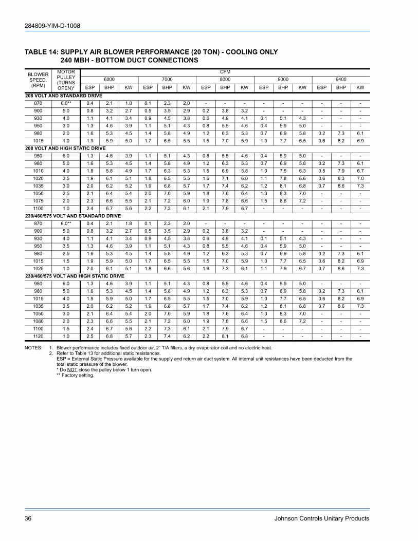
284809-YIM-D-1008
36 Johnson Controls Unitary Products
NOTES: 1. Blower performance includes fixed outdoor air, 2” T/A filters, a dry evaporator coil and no electric heat.2. Refer to Table 13 for additional static resistances.
ESP = External Static Pressure available for the supply and return air duct system. All internal unit resistances have been deducted from the total static pressure of the blower.* Do NOT close the pulley below 1 turn open.** Factory setting.
TABLE 14: SUPPLY AIR BLOWER PERFORMANCE (20 TON) - COOLING ONLY240 MBH - BOTTOM DUCT CONNECTIONS
BLOWERSPEED,(RPM)
MOTORPULLEY(TURNSOPEN)*
CFM6000 7000 8000 9000 9400
ESP BHP KW ESP BHP KW ESP BHP KW ESP BHP KW ESP BHP KW
208 VOLT AND STANDARD DRIVE870 6.0** 0.4 2.1 1.8 0.1 2.3 2.0 - - - - - - - - -900 5.0 0.8 3.2 2.7 0.5 3.5 2.9 0.2 3.8 3.2 - - - - - -930 4.0 1.1 4.1 3.4 0.9 4.5 3.8 0.6 4.9 4.1 0.1 5.1 4.3 - - -950 3.0 1.3 4.6 3.9 1.1 5.1 4.3 0.8 5.5 4.6 0.4 5.9 5.0 - - -980 2.0 1.6 5.3 4.5 1.4 5.8 4.9 1.2 6.3 5.3 0.7 6.9 5.8 0.2 7.3 6.11015 1.0 1.9 5.9 5.0 1.7 6.5 5.5 1.5 7.0 5.9 1.0 7.7 6.5 0.6 8.2 6.9
208 VOLT AND HIGH STATIC DRIVE950 6.0 1.3 4.6 3.9 1.1 5.1 4.3 0.8 5.5 4.6 0.4 5.9 5.0 - - -980 5.0 1.6 5.3 4.5 1.4 5.8 4.9 1.2 6.3 5.3 0.7 6.9 5.8 0.2 7.3 6.11010 4.0 1.8 5.8 4.9 1.7 6.3 5.3 1.5 6.9 5.8 1.0 7.5 6.3 0.5 7.9 6.71020 3.5 1.9 6.1 5.1 1.8 6.5 5.5 1.6 7.1 6.0 1.1 7.8 6.6 0.6 8.3 7.01035 3.0 2.0 6.2 5.2 1.9 6.8 5.7 1.7 7.4 6.2 1.2 8.1 6.8 0.7 8.6 7.31050 2.5 2.1 6.4 5.4 2.0 7.0 5.9 1.8 7.6 6.4 1.3 8.3 7.0 - - -1075 2.0 2.3 6.6 5.5 2.1 7.2 6.0 1.9 7.8 6.6 1.5 8.6 7.2 - - -1100 1.0 2.4 6.7 5.6 2.2 7.3 6.1 2.1 7.9 6.7 - - - - - -
230/460/575 VOLT AND STANDARD DRIVE870 6.0** 0.4 2.1 1.8 0.1 2.3 2.0 - - - - - - - - -900 5.0 0.8 3.2 2.7 0.5 3.5 2.9 0.2 3.8 3.2 - - - - - -930 4.0 1.1 4.1 3.4 0.9 4.5 3.8 0.6 4.9 4.1 0.1 5.1 4.3 - - -950 3.5 1.3 4.6 3.9 1.1 5.1 4.3 0.8 5.5 4.6 0.4 5.9 5.0 - - -980 2.5 1.6 5.3 4.5 1.4 5.8 4.9 1.2 6.3 5.3 0.7 6.9 5.8 0.2 7.3 6.11015 1.5 1.9 5.9 5.0 1.7 6.5 5.5 1.5 7.0 5.9 1.0 7.7 6.5 0.6 8.2 6.91025 1.0 2.0 6.1 5.1 1.8 6.6 5.6 1.6 7.3 6.1 1.1 7.9 6.7 0.7 8.6 7.3
230/460/575 VOLT AND HIGH STATIC DRIVE 950 6.0 1.3 4.6 3.9 1.1 5.1 4.3 0.8 5.5 4.6 0.4 5.9 5.0 - - -980 5.0 1.6 5.3 4.5 1.4 5.8 4.9 1.2 6.3 5.3 0.7 6.9 5.8 0.2 7.3 6.11015 4.0 1.9 5.9 5.0 1.7 6.5 5.5 1.5 7.0 5.9 1.0 7.7 6.5 0.6 8.2 6.91035 3.5 2.0 6.2 5.2 1.9 6.8 5.7 1.7 7.4 6.2 1.2 8.1 6.8 0.7 8.6 7.31050 3.0 2.1 6.4 5.4 2.0 7.0 5.9 1.8 7.6 6.4 1.3 8.3 7.0 - - -1080 2.0 2.3 6.6 5.5 2.1 7.2 6.0 1.9 7.8 6.6 1.5 8.6 7.2 - - -1100 1.5 2.4 6.7 5.6 2.2 7.3 6.1 2.1 7.9 6.7 - - - - - -1120 1.0 2.5 6.8 5.7 2.3 7.4 6.2 2.2 8.1 6.8 - - - - - -

284809-YIM-D-1008
Johnson Controls Unitary Products 37
NOTES: 1. Blower performance includes a gas-fired heat exchanger, fixed outdoor air, two-inch T/A filters and a dry evaporator coil.2. Refer to the additional Static Resistances table.
ESP = External Static Pressure available for the supply and return air duct system. All internal unit resistances have been deducted from the total static pressure of the blower.* Do NOT close the pulley below 1 turn open.** Factory setting.
TABLE 15: SUPPLY AIR BLOWER PERFORMANCE (15 TON) - GAS HEAT180 MBH - BOTTOM DUCT CONNECTIONS
BLOWERSPEED,(RPM)
MOTORPULLEY(TURNSOPEN)*
CFM4500 5250 6000 6750 7200
ESP BHP KW ESP BHP KW ESP BHP KW ESP BHP KW ESP BHP KW
208 VOLT AND STANDARD DRIVE850 6.0** 0.9 2.4 2.1 0.6 2.9 2.6 0.3 3.4 3.0 - - - - - -870 5.5 1.0 2.5 2.2 0.7 3.0 2.7 0.4 3.5 3.1 - - - - - -915 4.5 1.1 2.6 2.4 0.8 3.1 2.8 0.5 3.6 3.2 0.2 4.1 3.7 - - -965 3.5 1.2 2.7 2.5 0.9 3.2 2.9 0.6 3.7 3.3 0.4 4.4 3.0 0.2 5.0 4.5980 3.0 1.3 2.9 2.6 1.0 3.4 3.0 0.7 3.8 3.4 0.5 4.5 4.0 0.3 5.1 4.61010 2.0 1.4 3.0 2.7 1.1 3.6 3.2 0.8 4.0 3.6 0.6 4.7 4.2 0.4 5.4 4.81040 1.0 1.6 3.2 2.9 1.3 3.8 3.4 1.0 4.4 3.9 0.8 5.0 4.5 0.6 5.6 5.0
208 VOLT AND HIGH STATIC DRIVE965 6.0 1.2 2.7 2.5 0.9 3.2 2.9 0.6 3.7 3.3 0.4 4.4 3.9 0.2 5.0 4.5980 5.5 1.3 2.9 2.6 1.0 3.4 3.0 0.7 3.8 3.4 0.5 4.5 4.0 0.3 5.1 4.61025 4.5 1.4 3.1 2.8 1.2 3.6 3.2 0.9 4.1 3.7 0.7 4.8 4.3 0.4 5.5 4.91065 3.5 1.6 3.4 3.0 1.4 3.9 3.5 1.1 4.5 4.0 0.9 5.1 4.6 - - -1125 2.0 1.9 3.6 3.2 1.7 4.4 3.9 1.4 5.0 4.5 1.2 5.8 5.2 - - -1170 1.0 2.1 3.9 3.5 1.9 4.7 4.2 1.6 5.5 4.9 - - - - - -
230/460/575 VOLT AND STANDARD DRIVE870 6.0** 1.0 2.5 2.2 0.7 3.0 2.7 0.4 3.5 3.1 - - - - - -915 5.0 1.1 2.6 2.4 0.8 3.1 2.8 0.5 3.6 3.2 0.2 4.1 3.7 - - -965 4.0 1.2 2.7 2.5 0.9 3.2 2.9 0.6 3.7 3.3 0.4 4.4 3.9 0.2 5.0 4.5980 3.5 1.3 2.9 2.6 1.0 3.4 3.0 0.7 3.8 3.4 0.5 4.5 4.0 0.3 5.1 4.61015 2.5 1.4 3.0 2.7 1.1 3.6 3.2 0.8 4.0 3.6 0.6 4.7 4.2 0.4 5.4 4.81050 1.5 1.5 3.1 2.8 1.2 3.7 3.3 0.9 4.2 3.8 0.7 4.9 4.4 0.5 5.7 5.11065 1.0 1.6 3.4 3.0 1.4 3.9 3.5 1.1 4.5 4.0 0.9 5.1 4.6 - - -
230/460/575 VOLT AND HIGH STATIC DRIVE980 6.0 1.3 2.9 2.6 1.0 3.4 3.0 0.7 3.8 3.4 0.5 4.5 4.0 0.3 5.1 4.61045 4.5 1.6 3.2 2.9 1.3 3.8 3.4 1.0 4.4 3.9 0.8 5.0 4.5 0.6 5.6 5.01065 4.0 1.7 3.4 3.0 1.4 3.9 3.5 1.1 4.5 4.0 0.9 5.1 4.6 - - -1125 2.5 1.9 3.6 3.2 1.7 4.4 3.9 1.4 5.0 4.5 1.2 5.8 5.2 - - -1170 1.5 2.1 3.9 3.5 1.8 4.7 4.2 1.6 5.5 4.9 - - - - - -1190 1.0 2.2 4.0 3.6 1.9 4.8 4.3 1.7 5.6 5.0 - - - - - -

284809-YIM-D-1008
38 Johnson Controls Unitary Products
NOTES: 1. Blower performance includes a gas-fired heat exchanger, fixed outdoor air, two-inch T/A filters and a dry evaporator coil.2. Refer to the additional Static Resistances table.
ESP = External Static Pressure available for the supply and return air duct system. All internal unit resistances have been deducted from the total static pressure of the blower.* Do NOT close the pulley below 1 turn open.** Factory setting.
TABLE 16: SUPPLY AIR BLOWER PERFORMANCE (17.5 TON) - GAS HEAT210 MBH - BOTTOM DUCT CONNECTIONS
BLOWERSPEED,(RPM)
MOTORPULLEY(TURNSOPEN)*
CFM6000 7000 8000 9000
ESP BHP KW ESP BHP KW ESP BHP KW ESP BHP KW
208 VOLT AND STANDARD DRIVE870 6.0** 1.3 3.6 3.0 0.7 4.3 3.7 0.2 5.1 4.3 - - -900 5.0 1.4 3.8 3.2 0.9 4.7 4.0 0.4 5.6 4.7 - - -930 4.0 1.6 4.1 3.4 1.1 5.0 4.2 0.6 5.9 5.0 0.1 6.7 5.7950 3.0 1.7 4.2 3.6 1.3 5.1 4.3 0.8 6.0 5.1 0.2 6.9 5.8980 2.0 1.9 4.5 3.8 1.5 5.4 4.5 1.0 6.3 5.3 0.4 7.2 6.1995 1.5 2.1 4.6 3.9 1.6 5.5 4.7 1.1 6.4 5.4 0.5 7.5 6.3
1015 1.0 2.2 4.8 4.0 1.7 4.7 4.8 1.2 6.6 5.6 0.7 7.8 6.6208 VOLT AND HIGH STATIC DRIVE
950 6.0 1.7 4.2 3.6 1.3 5.1 4.3 0.8 6.0 5.1 0.2 6.9 5.8980 5.0 1.9 4.5 3.8 1.5 5.4 4.5 1.0 6.3 5.3 0.4 7.2 6.1995 4.5 2.1 4.5 3.9 1.6 5.5 4.7 1.1 6.4 5.4 0.5 7.5 6.3
1025 3.5 2.3 4.9 4.1 1.8 5.8 4.9 1.3 6.7 5.7 0.7 8.0 6.71050 2.5 2.5 5.1 4.3 2.0 6.1 5.1 1.4 7.1 6.0 0.9 8.4 7.01065 2.0 2.6 5.3 4.4 2.1 6.3 5.3 1.5 7.3 6.2 1.0 8.6 7.21100 1.0 2.9 5.6 4.7 2.3 6.8 5.7 1.8 7.9 6.6 - - -
230/460/575 VOLT AND STANDARD DRIVE870 6.0** 1.3 3.6 3.0 0.7 4.3 3.7 0.2 5.1 4.3 - - -900 5.0 1.4 3.8 3.2 0.9 4.7 4.0 0.4 5.6 4.7 - - -930 4.0 1.6 4.1 3.4 1.1 5.0 4.2 0.6 5.9 5.0 0.1 6.7 5.7950 3.5 1.7 4.2 3.6 1.3 5.1 4.3 0.8 6.0 5.1 0.2 6.9 5.8965 2.5 1.9 4.5 3.8 1.5 5.4 4.5 1.0 6.3 5.3 0.4 7.2 6.1995 2.0 2.1 4.6 3.9 1.6 5.5 4.7 1.1 6.4 5.4 0.5 7.5 6.3
1015 1.5 2.2 4.8 4.0 1.7 5.7 4.8 1.2 6.6 5.6 0.6 7.8 6.61025 1.0 2.3 4.9 4.1 1.8 5.8 4.9 1.3 6.7 5.7 0.7 8.0 6.7
230/460/575 VOLT AND HIGH STATIC DRIVE950 6.0 1.7 4.2 3.6 1.3 5.1 4.3 0.8 6.0 5.1 0.2 6.9 5.8980 5.0 1.9 4.5 3.8 1.5 5.4 4.5 1.0 6.3 5.3 0.4 7.2 6.1995 4.5 2.1 4.6 3.9 1.6 5.5 4.7 1.1 6.4 5.4 0.5 7.5 6.3
1015 4.0 2.2 4.8 4.0 1.7 5.7 4.8 1.2 6.6 5.6 0.6 7.8 6.61025 3.5 2.3 4.9 4.1 1.8 5.8 4.9 1.3 6.7 5.7 0.7 8.0 6.71050 3.0 2.5 5.1 4.3 2.0 6.1 5.1 1.4 7.1 6.0 0.9 8.4 7.01065 2.5 2.6 5.3 4.4 2.1 6.3 5.3 1.5 7.3 6.2 1.0 8.6 7.21100 1.5 2.9 5.6 4.7 2.3 6.8 4.7 1.8 7.9 6.6 - - -1120 1.0 3.1 5.8 4.9 2.5 7.0 5.9 1.9 8.3 6.9 - - -

284809-YIM-D-1008
Johnson Controls Unitary Products 39
NOTES: 1. Blower performance includes a gas-fired heat exchanger, fixed outdoor air, two-inch T/A filters and a dry evaporator coil.2. Refer to the additional Static Resistances table.
ESP = External Static Pressure available for the supply and return air duct system. All internal unit resistances have been deducted from the total static pressure of the blower.* Do NOT close the pulley below 1 turn open.** Factory setting.
TABLE 17: SUPPLY AIR BLOWER PERFORMANCE (20 TON) - GAS HEAT240 MBH - BOTTOM DUCT CONNECTIONS
BLOWERSPEED,(RPM)
MOTORPULLEY(TURNSOPEN)*
CFM6000 7000 8000 9000 9400
ESP BHP KW ESP BHP KW ESP BHP KW ESP BHP KW ESP BHP KW
208 VOLT AND STANDARD DRIVE870 6.0** 1.3 3.6 3.0 0.7 4.3 3.7 0.2 5.1 4.3 - - - - - -900 5.0 1.4 3.8 3.2 0.9 4.7 4.0 0.4 5.6 4.7 - - - - - -930 4.0 1.6 4.1 3.4 1.1 5.0 4.2 0.6 5.9 5.0 0.1 6.7 5.7 - - -950 3.0 1.7 4.2 3.6 1.3 5.1 4.3 0.8 6.0 5.1 0.2 6.9 5.8 - - -980 2.0 1.9 4.5 3.8 1.5 5.4 4.5 1.0 6.3 5.3 0.4 7.2 6.1 0.1 8.5 7.1995 1.5 2.1 4.6 3.9 1.6 5.5 4.7 1.1 6.4 5.4 0.5 7.5 6.3 0.2 8.6 7.31015 1.0 2.2 4.8 4.0 1.7 4.7 4.8 1.2 6.6 5.6 0.7 7.8 6.6 - - -
208 VOLT AND HIGH STATIC DRIVE950 6.0 1.7 4.2 3.6 1.3 5.1 4.3 0.8 6.0 5.1 0.2 6.9 5.8 - - -980 5.0 1.9 4.5 3.8 1.5 5.4 4.5 1.0 6.3 5.3 0.4 7.2 6.1 0.1 8.5 7.1995 4.5 2.1 4.5 3.9 1.6 5.5 4.7 1.1 6.4 5.4 0.5 7.5 6.3 0.2 8.6 7.31025 3.5 2.3 4.9 4.1 1.8 5.8 4.9 1.3 6.7 5.7 0.7 8.0 6.7 - - -1050 2.5 2.5 5.1 4.3 2.0 6.1 5.1 1.4 7.1 6.0 0.9 8.4 7.0 - - -1065 2.0 2.6 5.3 4.4 2.1 6.3 5.3 1.5 7.3 6.2 1.0 8.6 7.2 - - -1100 1.0 2.9 5.6 4.7 2.3 6.8 5.7 1.8 7.9 6.6 - - - - - -
230/460/575 VOLT AND STANDARD DRIVE870 6.0** 1.3 3.6 3.0 0.7 4.3 3.7 0.2 5.1 4.3 - - - - - -900 5.0 1.4 3.8 3.2 0.9 4.7 4.0 0.4 5.6 4.7 - - - - - -930 4.0 1.6 4.1 3.4 1.1 5.0 4.2 0.6 5.9 5.0 0.1 6.7 5.7 - - -950 3.5 1.7 4.2 3.6 1.3 5.1 4.3 0.8 6.0 5.1 0.2 6.9 5.8 - - -965 2.5 1.9 4.5 3.8 1.5 5.4 4.5 1.0 6.3 5.3 0.4 7.2 6.1 0.1 8.5 7.1995 2.0 2.1 4.6 3.9 1.6 5.5 4.7 1.1 6.4 5.4 0.5 7.5 6.3 0.2 8.6 7.31015 1.5 2.2 4.8 4.0 1.7 5.7 4.8 1.2 6.6 5.6 0.6 7.8 6.6 - - -1025 1.0 2.3 4.9 4.1 1.8 5.8 4.9 1.3 6.7 5.7 0.7 8.0 6.7 - - -
230/460/575 VOLT AND HIGH STATIC DRIVE950 6.0 1.7 4.2 3.6 1.3 5.1 4.3 0.8 6.0 5.1 0.2 6.9 5.8 - - -980 5.0 1.9 4.5 3.8 1.5 5.4 4.5 1.0 6.3 5.3 0.4 7.2 6.1 0.1 8.5 7.1995 4.5 2.1 4.6 3.9 1.6 5.5 4.7 1.1 6.4 5.4 0.5 7.5 6.3 0.2 8.6 7.31015 4.0 2.2 4.8 4.0 1.7 5.7 4.8 1.2 6.6 5.6 0.6 7.8 6.6 - - -1025 3.5 2.3 4.9 4.1 1.8 5.8 4.9 1.3 6.7 5.7 0.7 8.0 6.7 - - -1050 3.0 2.5 5.1 4.3 2.0 6.1 5.1 1.4 7.1 6.0 0.9 8.4 7.0 - - -1065 2.5 2.6 5.3 4.4 2.1 6.3 5.3 1.5 7.3 6.2 1.0 8.6 7.2 - - -1100 1.5 2.9 5.6 4.7 2.3 6.8 4.7 1.8 7.9 6.6 - - - - - -1120 1.0 3.1 5.8 4.9 2.5 7.0 5.9 1.9 8.3 6.9 - - - - -

284809-YIM-D-1008
40 Johnson Controls Unitary Products
NOTES: 1. Blower performance includes a gas-fired heat exchanger, fixed outdoor air, two-inch T/A filters and a dry evaporator coil.2. Refer to the additional Static Resistances table.
ESP = External Static Pressure available for the supply and return air duct system. All internal unit resistances have been deducted from the total static pressure of the blower.* Do NOT close the pulley below 1 turn open.** Factory setting.
TABLE 18: SUPPLY AIR BLOWER PERFORMANCE (25 TON) - GAS HEAT300 MBH - BOTTOM DUCT CONNECTIONS
BLOWERSPEED,(RPM)
MOTORPULLEY(TURNSOPEN)*
CFM7500 8750 10000 11250 12500
ESP BHP KW ESP BHP KW ESP BHP KW ESP BHP KW ESP BHP KW
208 VOLT AND STANDARD DRIVE975 6.0 1.2 5.9 4.9 5.0 7.3 6.0 - - - - - - - - -1005 5.0 1.4 6.2 5.1 0.7 7.7 6.3 - - - - - - - - -1040 4.0 1.6 6.6 5.4 0.9 8.1 6.7 0.2 9.7 8.0 - - - - - -1070 3.0 1.8 6.9 5.7 1.1 8.5 7.0 0.4 10.2 8.3 - - - - - -1100 2.0 2.0 7.3 6.0 1.3 8.9 7.3 0.6 10.6 8.7 - - - - - -1135 1.0 2.2 7.7 6.3 1.6 9.3 7.6 0.8 11.1 9.1 - - - - - -1165 0.0 2.4 8.0 6.6 1.8 9.7 8.0 1.0 11.6 9.5 0.2 13.5 11.0 - - -
208 VOLT AND HIGH STATIC DRIVE1140 6.0 2.2 7.7 6.3 1.6 9.4 7.7 0.9 11.2 9.2 - - - - - -1180 5.0 2.5 8.2 6.7 1.9 9.9 8.1 1.2 11.8 9.7 0.3 13.7 11.2 - - -1215 4.0 2.7 8.6 7.0 2.1 10.4 8.5 1.4 12.3 10.1 0.6 14.3 11.7 - - -1255 3.0 3.0 9.1 7.4 2.4 11.0 9.0 1.7 12.9 10.6 0.9 15.0 12.3 - - -1290 2.0 3.2 9.5 7.8 2.7 11.5 9.4 2.0 13.5 11.1 1.2 15.6 12.8 - - -1330 1.0 3.5 10.0 8.2 3.0 12.0 9.9 2.3 14.1 11.6 1.5 16.4 13.4 - - -1365 0.0 3.7 10.5 8.6 3.2 12.6 10.3 2.6 14.7 12.1 1.8 17.0 13.9 - - -
230/460/575 VOLT AND STANDARD DRIVE975 6.0* 1.4 5.9 4.9 1.0 7.3 6.0 0.5 8.8 7.2 - - - - - -1005 5.0 1.6 6.2 5.1 1.2 7.7 6.3 0.7 9.2 7.6 0.1 10.9 8.9 - - -1040 4.0 1.8 6.6 5.4 1.4 8.1 6.7 0.9 9.7 8.0 0.3 11.4 9.4 - - -1070 3.0 2.0 6.9 5.7 1.6 8.5 7.0 1.1 10.2 8.3 0.6 11.9 9.8 - - -1100 2.0 2.1 7.3 6.0 1.8 8.9 7.3 1.3 10.6 8.7 0.8 12.4 10.2 0.2 14.3 11.71135 1.0 2.4 7.7 6.3 2.0 9.3 7.6 1.6 11.1 9.1 1.0 13.0 10.6 0.4 14.9 12.21165 0.0 2.6 8.0 6.6 2.2 9.7 8.0 1.8 11.6 9.5 1.3 13.5 11.0 0.7 15.5 12.7
230/460/575 VOLT AND HIGH STATIC DRIVE1140 6.0 2.4 7.7 6.3 2.1 9.4 7.7 1.6 11.2 9.2 1.1 13.1 10.7 0.5 15.0 12.31180 5.0 2.7 8.2 6.7 2.3 9.9 8.1 1.9 11.8 9.7 1.4 13.7 11.2 0.8 15.8 12.91215 4.0 2.9 8.6 7.0 2.6 10.4 8.5 2.2 12.3 10.1 1.7 14.3 11.7 1.1 16.4 13.51255 3.0 3.2 9.1 7.4 2.9 11.0 9.0 2.5 12.9 10.6 2.0 15.0 12.3 1.4 17.2 14.11290 2.0 3.4 9.5 7.8 3.1 11.5 9.4 2.7 13.5 11.1 2.2 15.6 12.8 - - -1330 1.0 3.7 10.0 8.2 3.4 12.0 9.9 3.0 14.1 11.6 2.6 16.4 13.4 - - -1365 0.0 3.9 10.5 8.6 3.7 12.6 10.3 3.3 14.7 12.1 2.9 17.0 13.9 - - -

284809-YIM-D-1008
Johnson Controls Unitary Products 41
* Factory Setting Power Exhaust motor is a 3/4 HP, PSC type with sleeve bearings, a 48 frame and inherent protection.
TABLE 19: STATIC RESISTANCES1
DESCRIPTION
RESISTANCE, IWGCFM
15 TON 17.5 TON 20 TON 25 TON4500 6000 7200 6000 7500 9000 6000 8000 9400 7500 10000 12500
WET INDOOR COIL 0.1 0.1 0.1 0.1 0.1 0.1 0.1 0.1 0.1 0.1 0.1 0.1
ELECTRIC HEAT OPTIONS
18 KW 0.3 0.4 0.4 0.4 0.4 0.5 0.4 0.4 0.5 0.4 0.5 0.636 KW 0.3 0.4 0.5 0.4 0.5 0.5 0.4 0.5 0.5 0.5 0.5 0.654 KW 0.4 0.5 0.5 0.5 0.5 0.6 0.5 0.5 0.6 0.5 0.6 0.772 KW 0.4 0.5 0.5 0.5 0.5 0.6 0.5 0.5 0.6 0.5 0.6 0.7
ECONOMIZER OPTION 0.1 0.1 0.1 0.1 0.1 0.2 0.1 0.1 0.2 0.1 0.2 0.3
HORIZONTAL DUCT CONNECTIONS2 0.1 0.2 0.3 0.2 0.3 0.5 0.2 0.3 0.5 0.3 0.5 0.6
1. Deduct these resistance values from the available external static pressures shown in the respective Blower Performance Table (See Note 2 for exception.)
2. Since the resistance to air flow will be less for horizontal duct connections than for bottom duct connections, add these pressures to the ESP values on the respective unit’s blower performance table.
TABLE 20: POWER EXHAUST PERFORMANCE
MOTORSPEED
STATIC RESISTANCE OF RETURN DUCTWORK, IWG0.2 0.3 0.4 0.5 0.6
CFM KW CFM KW CFM KW CFM KW CFM KWHIGH* 5250 0.83 4500 0.85 4200 0.88 3750 0.93 3000 0.99
MEDIUM 4900 0.77 3900 0.79 3500 0.82 2900 0.85 - -LOW 4400 0.72 3700 0.74 3000 0.78 - - - -
TABLE 21: BLOWER MOTOR AND DRIVE DATA
MODELSIZE DRIVE
BLOWERRANGE(RPM)
MOTOR1 ADJUSTABLE MOTOR PULLEY FIXED BLOWER PULLEY BELT(NOTCHED)
HP FRAME EFF.(%)
DESIG-NATION
OUTSIDEDIA.(IN.)
PITCHDIA.(IN.)
BORE(IN.)
DESIG-NATION
OUTSIDEDIA.(IN.)
PITCHDIA.(IN.)
BORE(IN.)
DESIG-NATION
PITCHLENGTH
(IN.)QTY.
15 TONStandard 850/1065
5 184 T 83 1VP56 5.35 4.3-5.32 1-1/8BK90 8.75 8.4 1 BX81 82.8 1
HighStatic 965/1190 BK80 7.75 7.4 1 BX78 79.8 1
17.5 & 20 TON
Standard 870/10257.5 213 T 89 1VP68 6.75 5.5-6.52 1-3/8
BK120 11.75 11.4 1-3/16 BX83 84.8 1HighStatic 950/1120 BK110 10.75 10.4 1-3/16 BX81 82.8 1
25 TONStandard 975/1165
15 254 T 91 1VP75X 7.5 6.2-7.4 1-5/81B5V110 11.3 11.1 1-7/16 5VX860 86.0 1
HighStatic 1140/1365 1B5V94 9.7 9.5 1-7/16 5VX840 84.0 1
1. All motors have a nominal speed of 1800 RPM, a 1.15 service factor and a solid base. They can operate to the limit of their service factor because they are located in the moving air, upstream of any heating device.
2. Do NOT close this pulley below 1 turn open.

284809-YIM-D-1008
42 Johnson Controls Unitary Products
FIGURE 17 - CHARGING CHART - 15 TON
15 Ton Charging Chart
100
150
200
250
300
350
400
60 70 80 90 100
Suction Pressure (psi)
Dis
char
ge P
ress
ure
(psi
)115
105º
95º
85º
75º
Outdoor Temp (°F)
1. Make sure that both condenser fans are running w hen charging. One fan may sw itch offat low er ambient temperatures making the chart above inaccurate.2. This chart is applicable to unit w ith the TXV's left to the factory setting. If the TXV's havebeen adjusted in the f ield, The charging chart may no longer apply.
º
FIGURE 18 - CHARGING CHART - 17.5 TON
17.5 Ton Charging Chart
100
150
200
250
300
350
400
60 65 70 75 80 85 90 95 100Suction Pressure (psi)
Dis
char
ge P
ress
ure
(psi
)
115°105°
95°85°75°
Outdoor Temp (°F)
1. Make sure that both condenser fans are running when charging. One fan may switch off at lower ambient temperatures making the chart above inaccurate.2. This chart is applicable to unit with the TXV's left to the factory setting. If the TXV's have been adjusted in the field, The charging chart may no longer apply.
65°

284809-YIM-D-1008
Johnson Controls Unitary Products 43
FIGURE 19 - CHARGING CHART - 20 TON
20 Ton Charging Chart
100
150
200
250
300
350
400
60 65 70 75 80 85 90 95 100Suc tion Pressure (psi)
Dis
char
ge P
ress
ure
(psi
) 115°
105°
95°85°75°65°
Outdoor Temp (°F)
1. Make sure that both condenser fans are running when charging. One fan may switchoff at lower ambient temperatures making the chart above inaccurate.2. This chart is applicable to unit with the TXV's left to the factory setting. If the TXV'shave been adjusted in the field, the charging chart may no longer apply.
FIGURE 20 - CHARGING CHART - 25 TON
25 Ton Charging Chart
100
150
200
250
300
350
400
60 65 70 75 80 85 90 95 100Suction Pressure (psi)
Dis
char
ge P
ress
ure
(psi
)
115° 105°95°85°
75°65°
Outdoor Temp (°F)
1. Make sure that both condenser fans are running when charging. One fan may switch off at lower ambient temperatures making the chart above inaccurate.2. This chart is applicable to unit with the TXV's left to the factory setting. If the TXV's have been adjusted in the field, The charging chart may no longer apply.

284809-YIM-D-1008
44 Johnson Controls Unitary Products
PHASING
YORK MODEL DJ, units are properly phased at thefactory. Check for proper compressor rotation. If theblower or compressors rotate in the wrong direction atstart-up, the electrical connection to the unit is mis-phased. Change the incoming line connection phasingto obtain proper rotation. (Scroll compressors operatein only one direction. If the scroll is drawing low amper-age, has similar suction and discharge pressures, orproducing a high noise level, the scroll is misphased).
CHECKING SUPPLY AIR CFM
The RPM of the supply air blower will depend on therequired CFM, the unit accessories or options and thestatic resistances of both the supply and the return airduct systems. With this information, the RPM for thesupply air blower and the motor pulley adjustment(turns open) can be determined from the Blower Per-formance Data Tables.
High speed drive accessories (containing a smallerblower pulley and a shorter belt) are available for appli-cations requiring the supply air blower to producehigher CFM's and/or higher static pressures. UseModel 1LD0460 for 15 ton units, Model 1LD0417 for17.5 and 20 ton units, and Model 1LD0435 for 25 tonunits. Refer to the Blower Motor and Drive DataTable 21.
Note the following:
1. The supply air CFM must be within the limitationsshown in the Unit Application Data Table 1.
2. Pulleys can be adjusted in half turn increments.
3. The tension on the belt should be adjusted asshown in the Belt Adjustment Figure 21.
4. Tighten blower pulley and motor sheave set screwsafter any adjustments. Re-check set screws after10-12 hrs. run time is recommended.
AIR BALANCE
Scroll compressors require proper rotation tooperate correctly. Units are properly phased atthe factory. Do not change the internal wiring tomake the blower, condenser fans, or compres-sor rotate correctly.
Belt drive blower systems MUST be adjusted to the specific static and CFM requirements for the application. The belt drive blowers are NOT set at the factory for any specific static or CFM. Adjustments of the blower speed an belt tension are REQUIRED. Tighten blower pulley and motor sheave set screws after these adjustments. Re-checking set screws after 10-12 hrs. run time is recommended.
FIGURE 21 - BELT ADJUSTMENT
On VAV units be certain that the VFD drive isset to maximum output, exhaust dampers areclosed and individual space damper boxes arefull open.
VFD units with bypass must not be in bypassmode (‘LINE’ position) unless all individualspace dampers are full open.

284809-YIM-D-1008
Johnson Controls Unitary Products 45
Start the supply air blower motor. Adjust the resis-tances in both the supply and the return air duct sys-tems to balance the air distribution throughout theconditioned space. The job specifications may requirethat this balancing be done by someone other than theequipment installer.
To check the supply air CFM after the initial balancinghas been completed:
1. Remove the two 5/16" dot plugs from the blowermotor and the filter access panels shown in theDimensions and Clearances Figure 13.
2. Insert at least 8" of 1/4 inch tubing into each ofthese holes for sufficient penetration into the airflow on both sides of the indoor coil.
NOTE: The tubes must be inserted and held in a posi-tion perpendicular to the air flow so that veloc-ity pressure will not affect the static pressurereadings.
3. Using an inclined manometer, determine the pres-sure drop across a dry evaporator coil. Since themoisture on an evaporator coil may vary greatly,measuring the pressure drop across a wet coilunder field conditions would be inaccurate. Toassure a dry coil, the compressors should be deac-tivated while the test is being run.
4. Knowing the pressure drop across a dry coil, theactual CFM through the unit can be determinedfrom the curve in Pressure Drop vs. Supply AirCFM Figure 22.
After readings have been obtained, remove the tubesand reinstall the two 5/16" dot plugs that were removedin Step 1.
NOTE: DE-ENERGIZE THE COMPRESSORSBEFORE TAKING ANY TEST MEASURE-MENTS TO ASSURE A DRY INDOOR COIL.
OPERATION
SEQUENCE OF OPERATIONS OVERVIEW
For these units, the thermostat makes a circuitbetween "R" and "Y1" for the first stage of cooling.
The call is passed to the unit control board (UCB), whichthen determines whether the requested operation isavailable and, if so, which components to energize.
For gas heating, the UCB monitors the "W1" call butdoes not handle the operation of the gas furnace. Anignition control board controls the gas heater operation.
For electric heat units, the UCB passes the call to theelectric heater.
In both cases, when the "W1" call is sensed, the indoor airblower is energized following a specified heating delay.
If at any time a call for both heating and cooling arepresent, the heating operation will be performed. If oper-ating, the cooling system is halted as with a completionof a call for cooling. Heating always takes priority.
COOLING SEQUENCE OF OPERATION
CONTINUOUS BLOWER
By setting the room thermostat fan switch to "ON," thesupply air blower will operate continuously.
INTERMITTENT BLOWER
With the room thermostat fan switch set to "AUTO" andthe system switch set to either the "AUTO" or "HEAT"settings, the blower is energized whenever a cooling orheating operation is requested. The blower is ener-gized after any specified delay associated with theoperation.
FIGURE 22 - PRESSURE DROP ACROSS A DRY INDOOR COIL VS SUPPLY AIR CFM FOR ALL UNIT TONNAGES
PRESSURE DROP ACROSS A DRY INDOOR COIL VS SUPPLY AIR CFM
0
0.05
0.1
0.15
0.2
0.25
0.3
0.35
0.4
0.45
4000 5000 6000 7000 8000 9000 10000 11000 12000
NOMINAL AIR FLOW (CFM)
PR
ES
SU
RE
DR
OP
(IW
G)
Failure to properly adjust the total system airquantity can result in extensive blower damage.

284809-YIM-D-1008
46 Johnson Controls Unitary Products
When energized, the indoor blower has a minimum runtime of 30 seconds. Additionally, the indoor blower hasa delay of 10 seconds between operations.
OPTIONAL VAV BLOWER OPERATION
For units with VFD, the speed of the indoor blowermotor is controlled by duct static pressure. The ductstatic set point is the pressure that the drive will main-tain when operating the unit in VAV mode. If the ductstatic pressure reaches or exceeds the high-limit set-point, then the supply fan motor will be shutdown.
NO OUTDOOR AIR OPTIONS
When the thermostat calls for the first stage of cooling,the low-voltage control circuit from "R" to "Y1" and "G"is completed. For first stage cooling, compressor #1,condenser fan motor #1, and condenser fan motor #2(if the ambient temperature is above 60ºF), is ener-gized. After completing the specified fan on delay forcooling, the UCB will energize the blower motor.
When the thermostat calls for the second stage of cool-ing, the low-voltage control circuit from "R" to "Y2" iscompleted. Compressor #2, condenser fan motor #3,and condenser fan motor #4 (if the ambient tempera-ture is above 60ºF), is energized, provided it has notbeen locked-out.
If there is an initial call for both stages of cooling, theUCB will delay energizing compressor #2 by 30 sec-onds in order to avoid a power in rush.
Once the thermostat has been satisfied, it will de-ener-gize Y1 and Y2. If the compressors have satisfied theirminimum run times, the compressors and condenserfans are de-energized. Otherwise, the unit operateseach cooling system until the minimum run times forthe compressors have been completed. Upon the finalcompressor de-energizing, the blower is stopped fol-lowing the elapse of the fan off delay for cooling.
To be available, a compressor must not be locked-outdue to a high or low-pressure switch or freezestat tripand the anti-short cycle delay (ASCD) must haveelapsed.
ECONOMIZER WITH SINGLE ENTHALPY SENSOR
When the room thermostat calls for "first-stage" cooling,the low voltage control circuit from "R" to "G" and "Y1" iscompleted. The UCB energizes the blower motor (if thefan switch on the room thermostat is set in the "AUTO"position) and drives the economizer dampers from fullyclosed to their minimum position. If the enthalpy of theoutdoor air is below the setpoint of the enthalpy control-ler (previously determined), "Y1" energizes the econo-mizer. The dampers will modulate to maintain a constantsupply air temperature as monitored by the discharge airsensor. If the outdoor air enthalpy is above the setpoint,"Y1" energizes compressor #1, condenser fan motor #1,and condenser fan motor #2 (if the ambient temperatureis above 60°F).
When the thermostat calls for "second-stage" cooling,the low voltage control circuit from "R" to "Y2" is com-pleted. The UCB energizes the first available compres-sor If the enthalpy of the outdoor air is below thesetpoint of the enthalpy controller (i.e. first stage hasenergized the economizer), "Y2" will energize com-pressor #1. If the outdoor air is above the setpoint, "Y2"will energize compressor #2.
Once the thermostat has been satisfied, it will de-ener-gize Y1 and Y2. If the compressors have satisfied theirminimum run times, the compressors and condenserfans are de-energized. Otherwise, the unit operateseach cooling system until the minimum run times forthe compressors have been completed. Upon the finalcompressor de-energizing, the blower is stopped fol-lowing the elapse of the fan off delay for cooling, andthe economizer damper goes to the closed position. Ifthe unit is in continues fan operation the economizerdamper goes to the min. position.
ECONOMIZER WITH DUAL ENTHALPY SENSORS
The operation with the dual enthalpy sensors is identi-cal to the single sensor except that a second enthalpysensor is mounted in the return air. This return air sen-sor allows the economizer to choose between outdoorair and return air, whichever has the lowest enthalpyvalue, to provide maximum operating efficiency.
If the unit is operated with the manual bypassswitch in the LINE (BYPASS) position andthere are VAV boxes present in the duct sys-tem, then boxes must be driven to the full-openposition using a customer-supplied powersource to prevent over-pressurizing and possi-ble damage to the ductwork.

284809-YIM-D-1008
Johnson Controls Unitary Products 47
ECONOMIZER (SINGLE OR DUAL ENTHALPY) WITH POWER EXHAUST
This system operates as specified above with oneaddition. The power exhaust motor is energized 45seconds after the actuator position exceeds theexhaust fan setpoint on the economizer control. Whenthe power exhaust is operating, the second stage ofmechanical cooling will not operate. As always, the "R"to "G" connection provides minimum position but doesnot provide power exhaust operation.
ECONOMIZER WITH OPTIONAL VAV ORINTELLI-COMFORT™ CONTROL
The position of the outside air and return air dampersare controlled through a 2-10 VDC signal from the VAVor Intelli-Comfort™ control board. The economizer isenabled only in Occupied or Recovery mode. When thecontrol is not powered or is in Unoccupied mode, theoutside air dampers will be closed. When the supplyfan is powered and there is no Y1 call, or if free-coolingis unavailable, the control opens the economizerdampers to the minimum position setting.
Free-cooling is available if the outdoor air temperaturemeets one of the three criteria discussed below, basedupon the unit's configuration.
• Dry Bulb: The control refers to input from the Out-side Air Temperature sensor and will allow free-cooling when the outdoor temperature is less than both the First-Stage SAT Control setpoint plus 5 °F, and the Economizer OAT Enable setpoint.
• Single Enthalpy (optional): A field-installed, Out-door Air Humidity sensor is connected to the con-trol. When the measured outdoor enthalpy is below the Outside Air Enthalpy setpoint, and the outdoor temperature is less than the First-Stage SAT Con-trol setpoint plus 5 °F, free-cooling is available.
• Dual Enthalpy (optional): Both the field-installed Outdoor Air Humidity and the Return Air Humidity sensors are connected to the control. When the measured outdoor air enthalpy is less than the measured return air enthalpy, and the outdoor tem-perature is less than the First-Stage SAT Control setpoint plus 5 °F, free-cooling is available.
If free-cooling is available with a Y1 call, then the con-trol modulates the economizer dampers to maintain theFirst-Stage SAT Control setpoint, plus or minus onedegree. If free-cooling is unavailable, then 1st-stagemechanical cooling is initiated.
If at anytime the outdoor air temperature rises abovethe First-Stage SAT Control setpoint plus 5 °F, whilefree-cooling is available, then a Y1 call will also initiate1st-stage mechanical cooling.
For a Y2 call, free-cooling is available based upon thecriteria described above, except a Second-Stage SATControl setpoint is used in the determination.
Once the call for cooling has been satisfied, it will de-energize any compressors and condenser fans, afterthe minimum compressor run times have been satis-fied. Otherwise, the unit operates each cooling systemuntil the minimum run times for the compressors havebeen completed.
Upon de-energizing the final compressor, the blowerwill continue to run with the economizer damper in itsminimum position if in the Occupied mode; otherwise,the blower will stop following the elapse of the fan-offdelay for cooling, and the economizer outdoor damperwill close.
ECONOMIZER WITH OPTIONAL VAV BLOWER WITH POWER EXHAUST
The power exhaust motor is energized via the control-ler's EXH~ terminal and the ER relay, based on theposition of the economizer damper parameter settingsin the VAV control. Minimum run time is 10 seconds;minimum off time is 60 seconds. The outlet pressure ofthe power exhaust fan forces the barometric reliefdampers open; gravity closes the dampers when theexhaust fan is off.
ECONOMIZER WITH OPTIONAL INTELLI-COMFORT™ WITH POWER EXHAUST
The power exhaust motor is energized via the exhaustrelay based on the position of the economizer actua-tor's auxiliary switch adjustment screw. The adjustmentscrew represents the outdoor damper position at whichto activate power exhaust, and can be set between 25to 85 degrees open. The outlet pressure of the powerexhaust fan forces the barometric relief dampers open;gravity closes the dampers when the exhaust fan is off.
MOTORIZED OUTDOOR AIR DAMPERS
This system operation is the same as the units with nooutdoor air options with one exception. When the "R" to"G" circuit is complete, the motorized damper drivesopen to a position set by the thumbwheel on thedamper motor. When the "R" to "G" circuit is opened,the damper spring returns fully closed.

284809-YIM-D-1008
48 Johnson Controls Unitary Products
COOLING OPERATION ERRORS
Each cooling system is monitored for operation outsideof the intended parameters. Errors are handled asdescribed below. All system errors override minimumrun times for compressors.
HIGH-PRESSURE LIMIT SWITCH
During cooling operation, if a high-pressure limit switchopens, the UCB will de-energize the associated com-pressor, initiate the ASCD (Anti-short cycle delay), and,if the other compressor is idle, stop the condenserfans. If the call for cooling is still present at the conclu-sion of the ASCD, the UCB will re-energize the haltedcompressor.
Should a high-pressure switch open three times withintwo hours of operation, the UCB will lock-out the asso-ciated compressor and flash a code (see Table 27). Ifthe other compressor is inactive, the condenser fanswill be de-energized.
LOW-PRESSURE LIMIT SWITCH
The low-pressure limit switch is not monitored duringthe initial 30 seconds of a cooling system's operation.For the following 30 seconds, the UCB will monitor thelow-pressure switch to ensure it closes. If the low-pres-sure switch fails to close after the 30-second monitor-ing phase, the UCB will de-energize the associatedcompressor, initiate the ASCD, and, if the other com-pressor is idle, stop the condenser fans.
Once the low-pressure switch has been proven (closedduring the 30-second monitor period described above),the UCB will monitor the low-pressure limit switch forany openings. If the low-pressure switch opens forgreater than 5 seconds, the UCB will de-energize theassociated compressor, initiate the ASCD, and, if theother compressor is idle, stop the condenser fans.
If the call for cooling is still present at the conclusion ofthe ASCD, the UCB will re-energize the halted com-pressor.
Should a low-pressure switch open three times withinone hour of operation, the UCB will lock-out the associ-ated compressor and flash a code (Table 27). If theother compressor is inactive, the condenser fans willbe de-energized.
FREEZESTAT
During cooling operation, if a freezestat opens, theUCB will de-energize the associated compressor, initi-ate the ASCD, and, if the other compressor is idle, stopthe condenser fans. If the call for cooling is still present
at the conclusion of the ASCD, the UCB will re-ener-gize the halted compressor.
Should a freezestat open three times within two hours ofoperation, the UCB will lock-out the associated compres-sor and flash a code (Table 27). If the other compressor isinactive, the condenser fans will be de-energized.
LOW AMBIENT COOLING
To determine when to operate in low ambient mode,the UCB has a pair of terminals connected to a temper-ature-activated switch set at 45ºF. When the low ambi-ent switch is closed and the thermostat is calling forcooling, the UCB will operate in the low ambient mode.
Low ambient mode operates the compressors in thismanner: 10 minutes on, 5 minutes off. The indoorblower is operated throughout the cycle. The 5-minuteoff period is necessary to defrost the indoor coil.
Low ambient mode always begins with compressoroperation. Compressor minimum run time may extendthe minutes of compressor operation. The defrost cyclewill begin immediately following the elapse of the mini-mum run time.
When operating in low ambient mode, the UCB will notlockout the compressors due to a freezestat trip. How-ever, a freezestat trip will de-energize the associatedcompressor. If the call for cooling is still present at theend of the ASCD and the freezestat has closed, theunit will resume operation.
SAFETY CONTROLS
The unit control board monitors the following inputs foreach cooling system:1. A suction line freezestat to protect against low
evaporator temperatures due to a low airflow or alow return air temperature, (opens at 26 ± 5 °F andresets at 38 ± 5°F).
2. A high-pressure switch to protect against excessivedischarge pressures due to a blocked condensercoil or a condenser motor failure. For 15-ton units,the switch opens at 405 ± 7 psig and resets at 265 ±20 psig. For 17.5, 20 and 25 ton units, the switchopens at 380 ± 10 psig and resets at 300 ± 10 psig.
3. A low-pressure switch to protect against loss ofrefrigerant charge, (opens at 22 ± 5 psig and resetsat 45 ± 5 psig).
The above pressure switches are hard-soldered to theunit. The refrigeration systems are independently mon-itored and controlled. On any fault, only the associatedsystem will be affected by any safety/preventive action.The other refrigerant system will continue in operationunless it is affected by the fault as well.

284809-YIM-D-1008
Johnson Controls Unitary Products 49
The unit control board monitors the temperature limitswitch of electric heat units and the temperature limitswitch and the gas valve of gas furnace units.
COMPRESSOR PROTECTION
The compressors also have inherent (internal) protec-tion. If there is an abnormal temperature rise in a com-pressor, the protector will open to shut down thecompressor. The UCB incorporates features to minimizecompressor wear and damage. An anti-short cycle delay(ASCD) is utilized to prevent operation of a compressortoo soon after its previous run. Additionally, a minimumrun time is imposed any time a compressor is energized.
The ASCD is initiated on unit start-up and on any com-pressor reset or lock-out.
FLASH CODES
The UCB will initiate a flash code associated witherrors within the system. Refer to UNIT CONTROLBOARD FLASH CODES Table 27.
RESET
Remove the call for cooling, by raising thermostat set-ting higher than the conditioned space temperature.This resets any pressure or freezestat flash codes.
ELECTRIC HEATING SEQUENCE OF OPERATIONS
The following sequence describes the operation of theelectric heat section.
Single-stage heating: (applies only to 18 KW heater, allother heaters MUST use a two-stage thermostat:).
a. Upon a call for heat by the thermostat, the heatercontactor (6M) will be energized. After completingthe specified fan on delay for heating, the UCB willenergize the blower motor.
b. The thermostat will cycle the electric heat to satisfythe heating requirements of the conditioned space.
Two-stage heating: (applies to all heaters except 18KW):
a. Upon a call for first-stage heat by the thermostat, theheater contactor (6M) (6M & 7M on 72 KW, 240V)will be energized. After completing the specified fanon delay for heating, the UCB will energize theblower motor.
If the second stage of heat is required, heater con-tactor (7M) will be energized. Note that on the 54KW, 240V heater, heater contactors (7M & 8M) willbe energized and on the 72 KW, 240V heater,heater contactors (8M & 9M) will be energized. Aftercompleting the specified fan on delay for heating,the UCB will energize the blower motor.
b. The thermostat will cycle the electric heat to satisfythe heating requirements of the conditioned space.
NOTE: All 240 & 480V heaters are provided with man-ual reset backup protection limits. These willde-energize the heaters should the primarylimit fail to open or the contactors fail to open ina failure mode.
HEATING OPERATION ERRORS
TEMPERATURE LIMIT
If the UCB senses zero volts from the high temperaturelimit, the indoor blower motor is immediately energized.
This limit is monitored regardless of unit operation sta-tus, i.e. the limit is monitored at all times.
If the temperature limit opens three times within onehour, it will lock-on the indoor blower motor and a flashcode is initiated (See Table 27).
SAFETY CONTROLS
The unit control board monitors the temperature limitswitch of electric heat units.
The control circuit includes the following safety con-trols:
1. Temperature Limit Switch (TLS 1, 2).
This control is located inside the heater compart-ment and is set to open at the temperature indi-cated in the Limit Control Setting Table 22. It resets
For units with VFD and electric heat, the speedof the indoor blower motor continues to be con-trolled by duct static pressure via the VAV con-trol board.
If there are VAV boxes present in the duct sys-tem, the boxes must be driven to the full-openposition using a customer-supplied powersource to assure adequate airflow across theheating elements.

284809-YIM-D-1008
50 Johnson Controls Unitary Products
automatically. The limit switch operates when ahigh temperature condition, caused by inadequatesupply air flow occurs, thus shutting down theheater and energizing the blower.
2. Temperature Limit Switch (TLS 3, 4, 5 and 6).
This control is located inside the heater compart-ment and is set to open at the temperature indi-cated in the Limit Control Setting Table 22. It is amanual reset limit. These limit switches will de-energize the heaters should the primary limit fail toopen or the contactors fail to open in a failuremode.
FLASH CODES
The UCB will initiate a flash code associated witherrors within the system. Refer to UNIT CONTROLBOARD FLASH CODES Table 27.
RESET
Remove the call for heating by lowering the thermostatsetting lower than the conditioned space temperature.This resets any flash codes.
HEAT ANTICIPATOR SETPOINTS
It is important that the anticipator setpoint be correct.Too high of a setting will result in longer heat cycles anda greater temperature swing in the conditioned space.Reducing the value below the correct setpoint will giveshorter "ON" cycles and may result in the lowering of thetemperature within the conditioned space. Refer toTable 23 for the required heat anticipator setting.
GAS HEATING SEQUENCE OF OPERATIONS
The following sequence describes the operation of thegas heat section.
When the thermostat calls for the first stage of heating,the low-voltage control circuit from "R" to "W1" and "G"is completed, thru the UCB. The heat relay "RW1" isenergized. The "RW1-2" contacts close energizing thedraft motor control. The draft motor control contactsclose and start the draft motor. As the speed of thedraft motor reaches approximately 2500 RPM, the cen-trifugal switch contact, located on the end of the draftmotor shaft, closes to power the first stage ignitionmodule "IC1", thru the "RW1-1 contacts.
Ignition module "IC1" will immediately start the firststage igniter sparking and will open the redundantvalve located inside the first stage main gas valve"GV1" to allow a flow of gas to only the first stage carry-over tube. Only after the pilot flame has been ignitedand the presence of pilot flame detected at the "IC1" bya signal sent back through the flame sensor is sparkingterminated and the first stage main gas valve opened.
TABLE 22: LIMIT CONTROL SETTING
18
36
54
72
18
36
54
72
18
36
54
72
18
36
54
72
TEMPERATURE LIMIT
SWITCH 1, 2
OPENS, 0F
TEMPERATURE LIMIT
SWITCH 3, 4, 5, 6
OPENS, 0F
UNIT
(Tons)VOLTAGE
HEATER
kW
120 170
120 170
120 170
120 170
140 200
140 200
140 200
140 200
120
120
120
120
120
120
120
120
170
170
170
170
~
~
~
~
15
17.5, 20,
25
15,17.5,
20, 25
240
240
460
60015,17.5,
20, 25
TABLE 23: ELECTRIC HEAT ANTICIPATOR SETPOINTS
HEATERKW VOLTAGE
SETTING, AMPSTH1 TH2
18
208/230-3-60
0.29 -36 0.29 0.2954 0.29 0.5872 0.29 0.5818
460-3-60
0.29 -36 0.29 0.2954 0.29 0.2972 0.29 0.2918
575-3-60
0.29 -36 0.29 0.2954 0.29 0.2972 0.29 0.29
For units with VFD and gas heat, the speed ofthe indoor blower motor continues to be con-trolled by duct static pressure via the VAV con-trol board.
If there are VAV boxes present in the duct sys-tem, the boxes must be driven to the full-openposition using a customer-supplied powersource to assure adequate airflow across theheat exchanger tubes.

284809-YIM-D-1008
Johnson Controls Unitary Products 51
Gas flows into each of the main burners and is ignitedfrom the carryover tube flame.
After completing the specified fan on delay for heating,the UCB will energize the blower motor.
If "IC1" fails to detect a pilot flame, it will continue to tryfor a maximum of 85 seconds to ignite the pilot tube. Ifthe pilot flame is not detected, then "IC1" will lock outfirst stage furnace operation for five minutes or until24V power is removed from the module either at theunit or by resetting the room thermostat.
When the thermostat calls for the second stage ofheating, the low-voltage control circuit from "R" to "W2"is completed, thru the UCB. Heat relay "RW2" is ener-gized. The "RW2-1" contact is closed energizing thesecond stage ignition module "IC2". "IC2" will immedi-ately start the second stage igniter sparking and willopen the redundant valve located inside the secondstage main gas valve "GV2" to allow a flow of gas tothe second stage carryover tube. Only after the pilotflame has been ignited and the presence of pilot flamedetected at "IC2" by a signal sent back through theflame sensor is sparking terminated and the main gasvalve opened.
Gas flows into each of the second stage main burnersand is ignited from the carryover tube flame.
If "IC2" fails to detect a pilot flame, it will continue to tryfor a maximum of 85 seconds to ignite the pilot tube. Ifthe pilot flame is not detected, then "IC2" will lock outfirst stage furnace operation for five minutes or until24V power is removed from the module either at theunit or by resetting the room thermostat.
NOTE: That the second stage furnace can operateeven if first stage has locked out.
When the thermostat satisfies de-energizing the"RW2"and "RW1", thus opening all gas valves. Theblower motor will continue to run after the furnace isshut down until the specified fan off delay for heatinghas been satisfied. The UCB will de-energize theblower motor.
When the thermostat calls for the first stage of heating,the low-voltage control circuit from "R" to "W1" is com-pleted. A call for heat passes through the UCB to theignition control board (ICB). The UCB monitors the"W1" call and acts upon any call for heat. Once voltagehas been sensed at “W1”, the UCB will initiate the fanon delay for heating, energizing the indoor blower afterthe specified delay has elapsed.
When the thermostat has been satisfied, heating callsare ceased. The GV is immediately de-energized. Theblower is de-energized after the fan off delay for heat-ing has elapsed. The draft motor performs a 25-secondpost purge.
GAS HEATING OPERATION ERRORS
TEMPERATURE LIMIT
If the UCB senses zero volts from the high temperaturelimit, the indoor blower motor is immediately energized.When the UCB again senses 24 volts from the temper-ature limit, the draft motor will perform a 25-secondpost-purge and the indoor blower will be de-energizedfollowing the elapse of the fan off delay for heating.
This limit is monitored regardless of unit operation sta-tus, i.e. the limit is monitored at all times.
If the temperature limit opens three times within onehour, it will lock-on the indoor blower motor and a flashcode is initiated (See Table 27).
GAS VALVE
The UCB continuously monitors the GV. Any time theUCB senses voltage at the GV without a call for heatfor a continuous five-minute period, the UCB will lock-on the indoor blower and a flash code is initiated(Table 27). When voltage is no longer sensed at theGV, the UCB will de-energize the indoor blower follow-ing the elapse of the fan off delay for heating.
If voltage has been sensed at the GV for at least 15seconds during the fan on delay for heating and GVvoltage or "W1" is lost, the indoor blower is forced onfor the length of the fan off delay for heating.
SAFETY CONTROLS
The unit control board monitors the temperature limitswitch and the gas valve of gas furnace units.
FIGURE 23 - GAS VALVE PIPING
GASVALVE
GAS MAIN
MAIN VALVE
TO MAINBURNER
REDUNDANTVALVE
TO PILOT BURNER

284809-YIM-D-1008
52 Johnson Controls Unitary Products
The control circuit includes the following safety con-trols:
1. Limit Control (LS).
This control is located inside the heat exchangercompartment and is set to open at the temperatureindicated in the Limit Control Setting Table 24. Itresets automatically. The limit switch operateswhen a high temperature condition, caused byinadequate supply air flow occurs, thus shuttingdown the ignition control and closing the main gasvalves and energizing the blower.
2. Centrifugal Switch (CS).
If the draft motor should fail, the centrifugal switchattached to the shaft of the motor prevents the igni-tion controls and gas valves from being energized.
3. Redundant Gas Valve.
There are two separate gas valves in the furnace.Each valve contains a main and a redundant valve.The redundant valves are located upstream of themain gas valves. Should either or both of the maingas valves fail in the open position the redundantvalves serve as back-ups and shut off the flow ofgas.
4. Flame Sensor Rod / 100% Ignition Control Lock-Out.
The flame rods and controls are located per ProperFlame Adjustment Figure 26. If an ignition controlfails to detect a signal from the flame sensor indi-cating the pilot flame is properly ignited, then themain gas valve will not open. It will continue to tryand ignite the pilot for a maximum of 85 seconds,then if the pilot flame is not detected, the ignitioncontrol will lock out furnace operation until 24Vpower is removed from the module either at theunit or by resetting the room thermostat.
5. Rollout Switch.
This switch is located above the main burners inthe control compartment, which in the event of asustained main burner rollout shuts off and locksout both ignition controls closing both gas valves.The ignition controls lock out furnace operationuntil 24V power is removed from the controls eitherat the unit or by resetting the room thermostat.
NOTE: The auto reset rollout switch must reset beforeallowing furnace operation.
6. Auxiliary limit switch (AUX) -
This control is located inside the heat exchangercompartment and is set to open at 190°F. It is amanual reset switch. If AUX trips, then the primarylimit has not functioned correctly. Replace the pri-mary limit.
FLASH CODES
The UCB will initiate a flash code associated witherrors within the system. Refer to UNIT CONTROLBOARD FLASH CODES Table 27.
RESETS
Remove the call for heating by lowering the thermostatsetting lower than the conditioned space temperature.This resets any flash codes.
HEAT ANTICIPATOR SETPOINTS
It is important that the anticipator setpoint be correct.Too high of a setting will result in longer heat cycles
TABLE 24: LIMIT CONTROL SETTING
Units(Tons)
Capacity, MBH Limit ControlOpens, ºFInput Output
15, 17.5, 20 & 25 300 240 19515, 17.5, 20 & 25 400 320 195
FIGURE 24 - GAS VALVE AND CONTROLS
� � � � � � � � � � � �
� � � � � � � � � � � � �
� � � � � � �
� � �
� � �
� � � � �
� � �
� � �
� � � � �
� � � � � � � �� � � � � � � �
� � � � � � �
� � � � � � � � �
� � � � � � � � � � � � �
284809-YIM-D-1008
Johnson Controls Unitary Products 53
and a greater temperature swing in the conditionedspace. Reducing the value below the correct setpointwill give shorter "ON" cycles and may result in the low-ering of the temperature within the conditioned space.
START-UP (COOLING)
PRESTART CHECK LIST
After installation has been completed:
1. Check the electrical supply voltage being supplied.Be sure that it is the same as listed on the unitnameplate.
2. Set the room thermostat to the off position.
3. Turn unit electrical power on.
4. Set the room thermostat fan switch to on.
5. Check indoor blower rotation.
• If blower rotation is in the wrong direction. Refer to Phasing Section in general informa-tion section.
• Check blower drive belt tension.
6. Check the unit supply air (CFM). See "CHECKINGSUPPLY AIR CFM" on page 44.
7. Measure evaporator fan motor's amp draw.
8. Set the room thermostat fan switch to off.
9. Turn unit electrical power off.
OPERATING INSTRUCTIONS
1. Turn unit electrical power on.
2. Set the room thermostat setting to lower than theroom temperature.
3. First stage compressors will energize after thebuilt-in time delay (five minutes).
4. The second stage of the thermostat will energizesecond stage compressor if needed.
POST START CHECK LIST
1. Verify proper system pressures for both circuits.
2. Measure the temperature drop across the evapora-tor coil.
3. Measure the system Amperage draw across alllegs of 3 phase power wires.
4. Measure the condenser fan amp draw.
SHUT DOWN
1. Set the thermostat to highest temperature setting.
2. Turn off the electrical power to the unit.
START-UP (GAS HEAT)
PRE-START CHECK LIST
Complete the following checks before starting the unit.
1. Check the type of gas being supplied. Be sure thatit is the same as listed on the unit nameplate.
2. Make sure that the vent and combustion air hoodshave been properly installed.
OPERATING INSTRUCTIONS
TO LIGHT PILOT AND MAIN BURNERS:
1. Turn “off” electric power to unit.
2. Turn room thermostat to lowest setting.
3. Turn gas valve knob or switch to “on” position.
4. Turn “on” electric power to unit.
5. Set room thermostat to desired temperature.(If thermostat “set” temperature is above room tem-
TABLE 25: GAS HEAT ANTICIPATOR SETPOINTS
Gas ValveAnticipator Setpoint
1st Stage 2nd Stage
Honeywell VR84400.30 amp 0.11 amp
White-Rodgers 36C68
This furnace is equipped with an intermittentpilot and automatic re-ignition system. DONOT attempt to manually light the pilot.
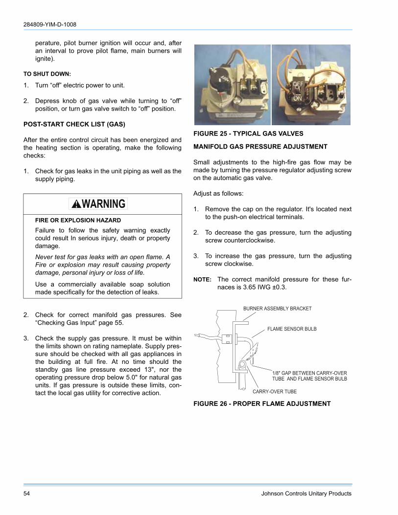
284809-YIM-D-1008
54 Johnson Controls Unitary Products
perature, pilot burner ignition will occur and, afteran interval to prove pilot flame, main burners willignite).
TO SHUT DOWN:
1. Turn “off” electric power to unit.
2. Depress knob of gas valve while turning to “off”position, or turn gas valve switch to “off” position.
POST-START CHECK LIST (GAS)
After the entire control circuit has been energized andthe heating section is operating, make the followingchecks:
1. Check for gas leaks in the unit piping as well as thesupply piping.
2. Check for correct manifold gas pressures. See“Checking Gas Input” page 55.
3. Check the supply gas pressure. It must be withinthe limits shown on rating nameplate. Supply pres-sure should be checked with all gas appliances inthe building at full fire. At no time should thestandby gas line pressure exceed 13", nor theoperating pressure drop below 5.0" for natural gasunits. If gas pressure is outside these limits, con-tact the local gas utility for corrective action.
MANIFOLD GAS PRESSURE ADJUSTMENT
Small adjustments to the high-fire gas flow may bemade by turning the pressure regulator adjusting screwon the automatic gas valve.
Adjust as follows:
1. Remove the cap on the regulator. It's located nextto the push-on electrical terminals.
2. To decrease the gas pressure, turn the adjustingscrew counterclockwise.
3. To increase the gas pressure, turn the adjustingscrew clockwise.
NOTE: The correct manifold pressure for these fur-naces is 3.65 IWG ±0.3.
FIRE OR EXPLOSION HAZARD
Failure to follow the safety warning exactlycould result In serious injury, death or propertydamage.
Never test for gas leaks with an open flame. AFire or explosion may result causing propertydamage, personal injury or loss of life.
Use a commercially available soap solutionmade specifically for the detection of leaks.
FIGURE 25 - TYPICAL GAS VALVES
FIGURE 26 - PROPER FLAME ADJUSTMENT
� � � � � � � � � � � � � � � � � � � � � � �
� � � � � � � � � � � � � � � � � � � � � � � � �
� � � � � � � � � � �
� � � � � � � � � � � � � � � �
� � � � � � � � � � � � � � � � � � �

284809-YIM-D-1008
Johnson Controls Unitary Products 55
PILOT CHECKOUT
The pilot flame should envelope the end of the flamesensor. To adjust pilot flame, (1) remove pilot adjust-ment cover screw, (2) increase or decrease the clear-ance for air to the desired level, (3) be sure to replacecover screw after adjustment to prevent possible gasleakage.
Put the system into operation and observe throughcomplete cycle to be sure all controls function properly.
BURNER INSTRUCTIONS
To check or change burners, pilot or orifices, CLOSEMAIN MANUAL SHUT-OFF VALVE AND SHUT OFFALL ELECTRIC POWER TO THE UNIT.
1. Remove the screws holding either end of the mani-fold to the burner supports.
2. Open the union fitting in the gas supply line justupstream of the unit gas valve and downstreamfrom the main manual shut-off valve.
3. Remove the gas piping closure panel.
4. Disconnect wiring to the gas valves and spark ignit-ors. Remove the manifold-burner gas valveassembly by lifting up and pulling back.
Burners are now accessible for service.
Reverse the above procedure to replace the assem-blies. Make sure that burners are level and seat at therear of the heat exchanger.
BURNER AIR SHUTTER ADJUSTMENT
Adjust burner shutters so no yellow flame is observedin the heat exchanger tubes.
CHECKING GAS INPUT
NATURAL GAS
1. Turn off all other gas appliances connected to thegas meter.
2. With the furnace turned on, measure the timeneeded for one revolution of the hand on the small-est dial on the meter. A typical gas meter usuallyhas a 1/2 or a 1 cubic foot test dial.
3. Using the number of seconds for each revolutionand the size of the test dial increment, find thecubic feet of gas consumed per hour from the GasRate - Cubic Feet Per Hour Table 26.
If the actual input is not within 5% of the furnace rating(with allowance being made for the permissible rangeof the regulator setting), replace the orifice spuds withspuds of the proper size.
NOTE: To find the Btu input, multiply the number ofcubic feet of gas consumed per hour by theBtu content of the gas in your particular locality(contact your gas company for this information- it varies widely from city to city.)
Example: By actual measurement, it takes 13 seconds for the hand on the 1-cubic foot dial to make a revolution with just a 300,000 Btuh furnace running. Read across to the column in the table above, headed “1 Cubic Foot”, where you will see that 278 cubic feet of gas per hour are consumed by the furnace at that rate. Multiply 278 x 1050 (the Btu rating of the gas obtained from the local gas company). The result is 292,425 Btuh, which is close to the 300,000 Btuh rating of the furnace.
FIGURE 27 - TYPICAL FLAME APPEARANCE
TABLE 26: GAS RATE - CUBIC FEET PER HOUR
Secondsfor One
Rev.
Size of Test Dial
1/2 cu. ft. 1 cu. ft.
468
10
450300228180
900600450360
1214161820
15012911310090
300257225200180
22242628
82756964
164150138129

284809-YIM-D-1008
56 Johnson Controls Unitary Products
ADJUSTMENT OF TEMPERATURE RISE
The temperature rise (or temperature differencebetween the return air and the heated air from the fur-nace) must lie within the range shown on the ratingplate and the data in the Gas Heat Application Table 4.
After the temperature rise has been determined, thecfm can be calculated as follows:
After about 20 minutes of operation, determine the fur-nace temperature rise. Take readings of both the returnair and the heated air in the ducts (about six feet fromthe furnace) where they will not be affected by radiantheat. Increase the blower cfm to decrease the temper-ature rise; decrease the blower cfm to increase therise. Refer to the Blower Motor and Drive DataTable 21.
BELT DRIVE BLOWER
All units have belt drive single-speed blower motors.The variable pitch pulley on the blower motor can beadjusted to obtain the desired supply air CFM.
TROUBLESHOOTING
COOLING TROUBLESHOOTING GUIDE
On calls for cooling, if the compressors are operatingbut the supply air blower motor does not energize aftera short delay (the room thermostat fan switch is in the“AUTO” position).
1. Turn the thermostat fan switch to the ON position.If the supply air blower motor does not energize, goto Step 3.
2. If the blower motor runs with the fan switch in theON position but will not run after the first compres-sor has energized when the fan switch is in theAUTO position, check the room thermostat for con-tact between R and G in the AUTO position duringcalls for cooling.
3. If the supply air blower motor does not energizewhen the fan switch is set to ON, check that linevoltage is being supplied to the contacts of the M3,contactor, and that the contactor is pulled in. Forunits with VFD, check that line voltage is beingsupplied to the M3-Auxiliary contacts. Check forloose wiring between the contactor and the supplyair blower motor.
4. If M3 is pulled in and voltage is supplied to M3,lightly touch the supply air blower motor housing. Ifit is hot, the motor may be off on internal protec-tion. Cancel any thermostat calls and set the fanswitch to AUTO. Wait for the internal overload toreset. Test again when cool.
5. If M3 is not pulled in, check for 24 volts at the M3coil. If 24 volts are present at M3 but M3 is notpulled in, replace the contactor.
6. Failing the above, if there is line voltage supplied atM3, M3 is pulled in, and the supply air blowermotor still does not operate, replace the motor.
For units with VFD, if there is line voltage suppliedat M3, M3 is pulled in, and the blower motor doesnot operate, check all power & control wiring con-nections to and from the drive and for any fault/warning messages displayed on the drive's digital
Troubleshooting of components may requireopening the electrical control box with thepower connected to the unit. Use extremecare when working with live circuits! Checkthe unit nameplate for the correct line voltageand set the voltmeter to the correct rangebefore making any connections with line termi-nals.
For troubleshooting of optional VFD, discon-nect all power to the drive. Be aware that highvoltages are present in the drive even afterpower has been disconnected. Capacitorswithin the drive must be allowed to dischargebefore beginning service.
When not necessary, shut off all electric powerto the unit prior to any of the following mainte-nance procedures so as to prevent personalinjury.
CFMBtuh Input x 0.8
=108. .x F Temp Riseo
Label all wires prior to disconnection when ser-vicing controls. Wiring errors can causeimproper and dangerous operation, whichcould cause injury to person and/or damageunit components. Verify proper operation afterservicing.

284809-YIM-D-1008
Johnson Controls Unitary Products 57
display (refer to the drive user manual for fulldescriptions, if necessary). Clear any fault bypressing 'RESET' on the drive's keypad and takeany corrective action as needed. If the motor stilldoes not operate, replace the motor.
7. If 24 volts is not present at M3, check that 24 voltsis present at the UCB supply air blower motor ter-minal, “FAN”. If 24 volts is present at the FAN,check for loose wiring between the UCB and M3.
8. If 24 volts is not present at the “FAN” terminal,check for 24 volts from the room thermostat. If 24volts are not present from the room thermostat,check for the following:
a. proper operation of the room thermostat (contactbetween R and G with the fan switch in the ON posi-tion and in the AUTO position during operationcalls), b. proper wiring between the room thermostatand the UCB, and c. loose wiring from the roomthermostat to the UCB.
9. If 24 volts is present at the room thermostat but notat the UCB, check for proper wiring between thethermostat and the UCB, i.e. that the thermostat Gterminal is connected to the G terminal of the UCB,and for loose wiring.
10. If the thermostat and UCB are properly wired,replace the UCB.
On calls for cooling, the supply air blower motor isoperating but compressor #1 is not (the room thermo-stat fan switch is in the “AUTO” position).
1. If installed, check the position of the economizerblades. If the blades are open, the economizer isproviding free cooling and the compressors will notimmediately operate. If both stages of cooling arerequested simultaneously and the economizer pro-vides free cooling, following a short delay compres-sor #1 will be energized unless it is locked out. Ifcompressor #1 is locked out, compressor #2 isenergized. Compressor #2 is always energized inplace of compressor #1 when compressor #1 isrequested but locked out.
2. If no economizer is installed or the economizer isnot opening to provide free cooling and compres-sor #1 does not energize on a call for cooling,check for line voltage at the compressor contactor,M1, and that the contactor is pulled in. Check for
loose wiring between the contactor and the com-pressor.
3. If M1 is pulled in and voltage is supplied at M1,lightly touch the compressor housing. If it is hot, thecompressor may be off on inherent protection.Cancel any calls for cooling and wait for the inter-nal overload to reset. Test again when cool.
4. If M1 is not pulled in, check for 24 volts at the M1coil. If 24 volts are present and M1 is not pulled in,replace the contactor.
5. Failing the above, if voltage is supplied at M1, M1is pulled in, and the compressor still does not oper-ate, replace the compressor.
6. If 24 volts is not present at M1, check for 24 volts atthe UCB terminal, C1. If 24 volts is present, checkfor loose wiring between C1 and the compressorcontactor.
7. If 24 volts is not present at the C1 terminal, checkfor 24 volts from the room thermostat at the UCBY1 terminal. If 24 volts is not present from the roomthermostat, check for the following: a) 24 volts atthe thermostat Y1 terminal, b) proper wiringbetween the room thermostat and the UCB, i.e. Y1to Y1, Y2 to Y2, and c) loose wiring from the roomthermostat to the UCB.
8. If 24 volts is present at the UCB Y1 terminal, thecompressor may be out due to an open high-pres-sure switch, low-pressure switch, or freezestat.Check for 24 volts at the HPS1, LPS1, and FS1terminals of the UCB. If a switch has opened, thereshould be a voltage potential between the UCB ter-minals, e.g. if LPS1 has opened, there will be a 24-volt potential between the LPS1 terminals.
9. If 24 volts is present at the UCB Y1 terminal andnone of the protection switches have opened, theUCB may have locked out the compressor forrepeat trips. The UCB should be flashing an alarmcode. If not, press and release the ALARMS buttonon the UCB. The UCB will flash the last five alarmson the LED. If the compressor is locked out, cancelany call for cooling. This will reset any compressorlock outs.
NOTE: While the above step will reset any lockouts,compressor #1 may be held off for the ASCD.See the next step.

284809-YIM-D-1008
58 Johnson Controls Unitary Products
10. If 24 volts is present at the UCB Y1 terminal andnone of the switches are open and the compressoris not locked out, the UCB may have the compres-sor in an ASCD. Check the LED for an indication ofan ASCD cycle. The ASCD should time out within5 minutes. Press and release the TEST button toreset all ASCDs.
11. If 24 volts is present at the UCB Y1 terminal andthe compressor is not out due to a protectiveswitch trip, repeat trip lock out, or ASCD, the econ-omizer terminals of the UCB may be improperlywired. Check for 24 volts at the Y1 “OUT” terminalof the UCB. If 24 volts is present, trace the wiringfrom Y1 “OUT” for incorrect wiring. If 24 volts is notpresent at the Y1 “OUT” terminal, the UCB must bereplaced.
12. For units without economizers:If 24 volts is presentat the Y1 OUT terminal, check for 24 volts at theY1 “ECON” terminal. If 24 volts is not present,check for loose wiring from the Y1 “OUT” terminalto the Mate-N-Lock plug, the jumper in the Mate-N-Lock plug, and in the wiring from the Mate-N-Lockplug to the Y1 “ECON” terminal.
13. For units with economizers: If 24 volts is present atthe Y1 “OUT” terminal, check for 24 volts at the Y1“ECON” terminal. If 24 volts is not present, check forloose wiring from the Y1 “OUT” terminal to the Mate-N-Lock plug, a poor connection between the UCBand economizer Mate-N-Lock plugs, loose wiringfrom the Mate-N-Lock plug to the economizer, backto the Mate-N-Lock plug, and from the Mate-N-Lockplug to the Y1 “ECON” terminal. If nothing is found,the economizer control may have faulted and is fail-ing to return the 24-volt “call” to the Y1 “ECON” ter-minal even though the economizer is not providingfree cooling. To test, disconnect the Mate-N-Locksand jumper between the WHITE and YELLOWwires of the UCB’s Mate-N-Lock plug. If compressor#1 energizes, there is a fault in the economizer wir-ing or the economizer control.
14. The UCB can be programmed to lock out compres-sor operation during free cooling and in low ambi-ent conditions. These options are not enabled bydefault. Local distributors can test the UCB for thisprogramming.
For units with factory installed economizers, theUCB is programmed to lock out compressor opera-tion when the LAS set point is reached.
For units without factory installed or with fieldinstalled economizers, the UCB allows compressoroperation all the time. This programming can bechecked or changed by the local distributor.
15. If none of the above corrected the error, test theintegrity of the UCB. Disconnect the C1 terminalwire and jumper it to the Y1 terminal. DO NOTjump the Y1 to C1 terminals. If the compressorengages, the UCB has faulted.
16. If none of the above correct the error, replace theUCB.
On calls for the second stage of cooling, the supply airblower motor and compressor #1 are operating butcompressor #2 is not (the room thermostat fan switchis in the “AUTO” position).
1. If installed, check the position of the economizerblades. If the blades are open, the economizer isproviding free cooling. If the second stage of cool-ing is requested, following a short delay, compres-sor #1 will be energized unless it is locked out.Typically, compressor #2 is energized only duringfree cooling if the call for the second stage of cool-ing persists for 20 minutes.
2. Compressor #2 will not energize simultaneouslywith compressor #1 if a call for both stages of cool-ing is received. The UCB delays compressor #2 by30 seconds to prevent a power surge. If after thedelay compressor #2 does not energize on a sec-ond stage call for cooling, check for line voltage atthe compressor contactor, M2, and that the contac-tor is pulled in. Check for loose wiring between thecontactor and the compressor.
3. If M2 is pulled in and voltage is supplied at M2,lightly touch the compressor housing. If it is hot, thecompressor may be off on inherent protection.Cancel any calls for cooling and wait for the inter-nal overload to reset. Test again when cool.
4. If M2 is not pulled in, check for 24 volts at the M2coil. If 24 volts is present and M2 is not pulled in,replace the contactor.
5. Failing the above, if voltage is supplied at M2, M2is pulled in, and the compressor still does not oper-ate, replace the compressor.
6. If 24 volts is not present at M2, check for 24 volts atthe UCB terminal, C2. If 24 volts are present,

284809-YIM-D-1008
Johnson Controls Unitary Products 59
check for loose wiring between C2 and the com-pressor contactor.
7. If 24 volts is not present at the C2 terminal, checkfor 24 volts from the room thermostat at the UCBY2 terminal. If 24 volts is not present from the roomthermostat, check for the following: a) 24 volts atthe thermostat Y2 terminal, b) proper wiringbetween the room thermostat and the UCB, i.e. Y1to Y1, Y2 to Y2, and c) loose wiring from the roomthermostat to the UCB.
8. If 24 volts is present at the UCB Y2 terminal, thecompressor may be out due to an open high-pres-sure switch, low-pressure switch, or freezestat.Check for 24 volts at the HPS2, LPS2, and FS2terminals of the UCB. If a switch has opened, thereshould be a voltage potential between the UCB ter-minals, e.g. if LPS2 has opened, there will be 24volts of potential between the LPS2 terminals.
9. If 24 volts is present at the UCB Y2 terminal andnone of the protection switches have opened, theUCB may have locked out the compressor forrepeat trips. The UCB should be flashing a code. Ifnot, press and release the ALARMS button on theUCB. The UCB will flash the last five alarms on theLED. If the compressor is locked out, remove anycall for cooling at the thermostat or by disconnect-ing the thermostat wiring at the Y2 UCB terminal.This will reset any compressor lock outs.
NOTE: While the above step will reset any lock outs,compressor #1 will be held off for the ASCD,and compressor #2 may be held off for a por-tion of the ASCD. See the next step.
10. If 24 volts is present at the UCB Y2 terminal andnone of the switches are open and the compressoris not locked out, the UCB may have the compres-sor in an ASCD. Check the LED for an indication ofan ASCD cycle. The ASCD should time out within5 minutes. Press and release the TEST button toreset all ASCDs.
11. The UCB can be programmed to lock out compres-sor operation during free cooling and in low ambi-ent conditions. These options are not enabled bydefault. Local distributors can test the UCB for thisprogramming.
For units with factory installed economizers, theUCB is programmed to lock out compressor opera-tion when the LAS set point is reached.
For units without factory installed or with fieldinstalled economizers, the UCB allows compressoroperation all the time. This programming can bechecked or changed by the local distributor.
12. If none of the above corrected the error, test theintegrity of the UGB. Disconnect the C2 terminalwire and jumper it to the Y2 terminal. DO NOTjump the Y2 to C2 terminals. If the compressorengages, the UCB has faulted.
13. If none of the above correct the error, replace theUCB.
On a call for cooling, the supply air blower motor andcompressor #2 are operating but compressor #1 is not(the room thermostat fan switch is in the “AUTO” posi-tion).
1. Compressor #2 is energized in place of compres-sor #1 when compressor #1 is unavailable for cool-ing calls. Check the UCB for alarms indicating thatcompressor #1 is locked out. Press and releasethe ALARMS button if the LED is not flashing analarm.
2. Check for line voltage at the compressor contactor,M1, and that the contactor is pulled in. Check forloose wiring between the contactor and the com-pressor.
3. If M1 is pulled in and voltage is supplied at M1,lightly touch the compressor housing. If it is hot, thecompressor may be off on inherent protection.Cancel any calls for cooling and wait for the inter-nal overload to reset. Test again when cool.
4. If M1 is not pulled in, check for 24 volts at the M1coil. If 24 volts is present and M1 is not pulled in,replace the contactor.
5. Failing the above, if voltage is supplied at M1, M1is pulled in, and the compressor still does not oper-ate, replace the compressor.
6. If 24 volts is not present at M1, check for 24 volts atthe UCB terminal, C1. If 24 volts is present, checkfor loose wiring between C1 and the compressorcontactor.
7. If 24 volts is not present at the C1 terminal, checkfor 24 volts from the room thermostat at the UCBY1 terminal. If 24 volts are not present at the UCB
284809-YIM-D-1008
60 Johnson Controls Unitary Products
Y1 terminal, the UCB may have faulted. Check for24 volts at the Y1 ECON terminal. If 24 volts is notpresent at Y1 “ECON”, the UCB has faulted. TheUCB should de-energize all compressors on a lossof call for the first stage of cooling, i.e. a loss if 24volts at the Y1 terminal.
8. If 24 volts are present at the UCB Y1 terminal, thecompressor may be out due to an open high-pres-sure switch, low-pressure switch, or freezestat.Check for 24 volts at the HPS1, LPS1, and FS1terminals of the UCB. If a switch has opened, thereshould be a voltage potential between the UCB ter-minals, e.g. if LPS1 has opened, there will be a 24-volt potential between the LPS1 terminals.
9. If 24 volts is present at the UCB Y1 terminal andnone of the protection switches have opened, theUCB may have locked out the compressor forrepeat trips. The UCB should be flashing a code. Ifnot, press and release the ALARMS button on theUCB. The UCB will flash the last five alarms on theLED. If the compressor is locked out, remove anycall for cooling. This will reset any compressor lockouts.
NOTE: While the above step will reset any lock outs,compressor #2 will be held off for the ASCD,and compressor #1 may be held off for a por-tion of the ASCD. See the next step.
10. If 24 volts is present at the UCB Y1 terminal andnone of the switches are open and the compressoris not locked out, the UCB may have the compres-sor in an ASCD. Check the LED for an indication ofan ASCD cycle. The ASCD should time out within5 minutes. Press and release the TEST button toreset all ASCDs.
11. If 24 volts is present at the UCB Y1 terminal andthe compressor is not out due to a protectiveswitch trip, repeat trip lock out, or ASCD, the econ-omizer terminals of the UCB may be improperlywired. Check for 24 volts at the Y1 “OUT” terminalof the UCB. If 24 volts is present, trace the wiringfrom Y1 “OUT” for incorrect wiring. If 24 volts is notpresent at the Y1 “OUT” terminal, the UCB must bereplaced.
12. For units without economizers: If 24 volts is presentat the Y1 “OUT” terminal, check for 24 volts at theY1 “ECON” terminal. If 24 volts is not present,check for loose wiring from the Y1 “OUT” terminalto the Mate-N-Lock plug, the jumper in the Mate-N-Lock plug, and in the wiring from the Mate-N-Lockplug to the Y1 “ECON” terminal.
For units with economizers: If 24 volts is present atthe Y1 “OUT” terminal, check for 24 volts at the Y1“ECON” terminal. If 24 volts is not present, checkfor loose wiring from the Y1 “OUT” terminal to theMate-N-Lock plug, a poor connection between theUCB and economizer Mate-N-Lock plugs, loosewiring from the Mate-N-Lock plug to the econo-mizer, back to the Mate-N-Lock plug, and from theMate-N-Lock plug to the Y1 “ECON” terminal. Theeconomizer control may have faulted and is notreturning the 24 volts to the Y1 “ECON” terminaleven though the economizer is not providing freecooling. To test the economizer control, disconnectthe Mate-N-Locks and jumper between the WHITEand YELLOW wires of the UCB’s Mate-N-Lockplug.
13. The UCB can be programmed to lock out compres-sor operation during free cooling and in low ambi-ent conditions. These options are not enabled bydefault. They can be checked by local distributors.
For units with factory installed economizers, theUCB is programmed to lock out compressor opera-tion when the LAS set point is reached.
For units without factory installed or with fieldinstalled economizers, the UCB allows compressoroperation all the time. This programming can bechecked or changed by the local distributor.
14. If none of the above corrected the error, test theintegrity of the UCB. Disconnect the C1 terminalwire and jumper it to the Y1 terminal. DO NOTjump the Y1 to C1 terminals. If the compressorengages, the UCB has faulted.
15. If none of the above correct the error, replace theUCB.

284809-YIM-D-1008
Johnson Controls Unitary Products 61
GAS HEAT TROUBLESHOOTING GUIDE
NOTE: To find the Btu input, multiply the number ofcubic feet of gas consumed per hour by theBtu content of the gas in your particular locality(contact your gas company for this information- it varies widely from city to city.).
On calls for heating, the draft motor operates and thefurnace lights but the supply air blower motor does notenergize after a short delay (the room thermostat fanswitch is in “AUTO” position).
1. Place the thermostat fan switch in the “ON” posi-tion. If the supply air blower motor energizes, go toStep 9.
2. If the supply air blower motor does not energizewhen the fan switch is set to “ON,” check that linevoltage is being supplied to the contacts of the M3contactor, and that the contactor is pulled in. Forunits with VFD, check that line voltage is beingsupplied to the M3-Auxiliary contacts. Check forloose wiring between the contactor and the supplyair blower motor.
3. If M3 is pulled in and voltage is supplied at M3,lightly touch the supply air blower motor housing. Ifit is hot, the motor may be off on inherent protec-tion. Cancel any thermostat calls and set the fanswitch to “AUTO”, wait for the internal overload toreset. Test again when cool.
4. If M3 is not pulled in, check for 24 volts at the M3coil. If 24 volts is present at M3 but M3 is not pulledin, replace the contactor.
5. Failing the above, if there is line voltage supplied atM3, M3 is pulled in, and the supply air blowermotor still does not operate, replace the motor.
For units with VFD, if there is line voltage suppliedat M3, M3 is pulled in, and the blower motor doesnot operate, check all power & control wiring con-nections to and from the drive and for any fault/warning messages displayed on the drive's digitaldisplay (refer to the drive user manual for fulldescriptions, if necessary). Clear any fault bypressing 'RESET' on the drive's keypad and takeany corrective action as needed. If the motor stilldoes not operate, replace the motor.
6. If 24 volts is not present at M3, check that 24 voltsis present at the supply air blower motor terminalon the UCB. If 24 volts is present at the UCB termi-nal, check for loose wiring between the UCB andM3.
a. If 24 volts is not present at the UCB supply airblower motor terminal, check for 24 volts from theroom thermostat. If 24 volts is not present from theroom thermostat, check for the following:
Troubleshooting of components may requireopening the electrical control box with thepower connected to the unit. Use extremecare when working with live circuits! Checkthe unit nameplate for the correct line voltageand set the voltmeter to the correct rangebefore making any connections with line termi-nals.
For troubleshooting of optional VFD, discon-nect all power to the drive. Be aware that highvoltages are present in the drive even afterpower has been disconnected. Capacitorswithin the drive must be allowed to dischargebefore beginning service.
When not necessary, shut off all electric powerto the unit prior to any of the following mainte-nance procedures so as to prevent personalinjury.
Label all wires prior to disconnection when ser-vicing controls. Wiring errors can causeimproper and dangerous operation, whichcould cause injury to person and/or damageunit components. Verify proper operation afterservicing.
The furnace may shut down on a high tem-perature condition during the procedure. Ifthis occurs, the UCB energize the supply airblower motor until the high temperature limithas reset. Caution should be used at alltimes as the supply air blower may energizeregardless of the room thermostat fan switchposition.

284809-YIM-D-1008
62 Johnson Controls Unitary Products
proper operation of the room thermostat (contactbetween R and G with the fan switch in the “ON”position and in the “AUTO” position during operationcalls), b) proper wiring between the room thermostatand the UCB, and c) loose wiring from the roomthermostat to the UCB.
7. If 24 volts is present at the room thermostat but notat the UCB, check for proper wiring between thethermostat and the UCB, i.e. that the thermostat Gterminal is connected to the G terminal of the UCB,and for loose wiring.
8. If the thermostat and UCB are properly wired,replace the UCB.
9. If the blower motor runs with the fan switch in the“ON” position but does not run shortly after the fur-nace has ignited when the fan switch is in the“AUTO” position, check the room thermostat forcontact between R and G during “W1” calls.
On calls for heating, the supply air blower operates butthe draft motor does not (the room thermostat fanswitch is in the “AUTO” position).
1. The draft motor has inherent protection. If themotor shell is hot to the touch, wait for the internaloverload to reset.
2. If the motor shell is cold with the room thermostatcalling for heat, check for line voltage at themotor's Mate-N-Lok connector attached to theevaporator partition. If line voltage is present,replace the draft motor.
3. If line voltage is not present, check for line voltageat the heat relay (RW1) contacts in the main con-trol box and check to see if the (RW1) is pulled in.
4. If the (RW1) relay is pulled in, check for a loose linevoltage connection.
5. If the (RW1) relay is not pulled in, check for 24 voltsat the (RW1) coil. If 24 volts is present, replace the(RW1) relay. If 24 volts is not present, check for aloose 24 volt connection back to the relay boardand check the connections from the room thermo-stat to the relay board. If all connections are cor-rect, replace the relay board.
The draft motor runs but the furnace does not light andthe sparker does not spark.
1. The ignition control (IC1, IC2) may be locked outdue to either a flame roll out or 100% shut off.These safety features are described above. If lock-out has occurred, 24V must be removed from theignition controls. This is done at the unit or byresetting the room thermostat. After resetting 24V,check for proper furnace operation. If lock-out con-tinues to occur, locate the source of the problemand correct.
2. Check all 24 volt connections from the relay boardto and in the gas heat section. Check low voltageconnections to the (ETD) located in the controlbox.
3. If the furnace is hot, it may be out on an over-tem-perature condition, wait for limit reset.
4. If the furnace is cold, check for 24 volts at wire 241attached to the electrical time delay (ETD) locatedin the main control box. If 24 volts is not found,replace the ETD.
5. 24 volts is found at wire 241, remove the wiresattached to the (TDR) and with a VOM, check forcontinuity across contacts 1 and 2. If none is found,the (TDR) is open and must be replaced. If there iscontinuity, re-attach the wires.With the draft motorrunning, check for 24 volts at terminal 4 of (RW1-2)and (RW2-1). If 24 volts is not present, the centrifu-gal switch (CS) has not closed or has gone bad.Check the line voltage to the unit - if it is correct,replace the draft motor. If line voltage is low, callthe power company.
6. Check for 24V at terminal 2 of (RW1-2 and RW2-1). If 24V is not present, check for 24V at (RW1and RW2) relay coils. If these relays are pulled in,then check for a loose connection at terminal 2 andterminal 4 of each relay. If no problem is found,then replace (RW1 and/or RW2) as required.
7. If 24 volts is present at the ignitor controls, checkall control wiring at the ignitor controls and the hightension wire to the ignitors. Check that the groundwires from the ignitor controls, the gas valves andpilot burners are all intact and making good electri-cal connection. Check to make sure that theceramic insulator on the pilot ignitors or sensors isnot broken or cracked, if all are intact, replace theignition control IC1 or IC2.

284809-YIM-D-1008
Johnson Controls Unitary Products 63
The draft motor runs and the ignitor sparks at the pilotburner but the pilot does not ignite and a gas odor isnot detected at the draft motor outlet.
1. Check to make sure gas is being supplied to theunit. Make sure that the gas pressure to the unit iswithin the proper limits as described in the “POSTSTART CHECK LIST” page 54 and that the pilotadjust screw is allowing some flow of gas asdescribed in “PILOT CHECKOUT” page 55.
2. Check all wiring between the ignitor control and thegas valve. Check to make sure the ground connec-tions are intact.
3. If the wiring is intact, check for 24 volts across ter-minals “PV” and “COMMON” on the ignitor control.If 24 volts is not present, replace the ignitor control.
4. If 24 volts is present, remove the pilot burner andremove the pilot orifice from the pilot burner. Theorifice is removed in the direction opposite the flowof gas. Inspect the orifice for obstruction. If it isclear, replace the main gas valve.
The ignitor sparks at the pilot burner but the pilot doesnot ignite and a gas odor is detected at the draft motoroutlet.
1. Adjust the pilot adjust screw on the gas valve asdescribed in “PILOT CHECKOUT” page 55.
2. Check the supply pressure as described in “POSTSTART CHECK LIST” page 54. Make adjustmentsas necessary.
3. Check the pilot orifice for obstruction as describedin paragraph above. Clean as needed but the prob-lem should not be the gas valve.
The pilot burner ignites but the ignitor continues tospark and the main burners do not ignite.
1. Make the same checks and adjustment asdescribed in “PILOT CHECKOUT” page 55.
2. Check the supply pressure as described in “POSTSTART CHECK LIST” page 54. Make adjustmentsas necessary.
3. Make sure that the pilot burner is not bent or dam-aged.
4. Make sure that the ground connections at the pilotburner, gas valve and ignitor control are intact.
Check the high tension wire for good electrical con-nection. If all are intact, replace the ignitor module.
The pilot burner lights and the spark stops but the mainburners do not light.
1. Check electrical connections between the ignitorcontrol and the gas valve. If intact, check for 24volts across terminals “MV” and “COMMON” termi-nals. If no voltage detected, replace ignitor control.If voltage is present, replace gas valve.
Furnace lights with roll-out or one burner has delayedignition.
1. Make sure that the pilot burner is aligned properlywith the carryover as described in “PILOT CHECK-OUT” page 55.
2. Make sure that the carryovers on adjoining burnersare screwed fast and are level with respect to oneanother.
Main burners light but exhibit erratic flame characteris-tics.
1. Adjust air shutters as described in “BURNER AIRSHUTTER ADJUSTMENT” page 55.
2. Check the main burner orifices for obstruction andalignment. Removal procedure is described inBURNER INSTRUCTIONS page 55. Clean orreplace burner orifices and burners as needed.
UNIT CONTROL BOARD FLASH CODES
Various flash codes are utilized by the unit controlboard (UCB) to aid in troubleshooting. Flash codes aredistinguished by the short on and off cycle used(approximately 200ms on and 200ms off). To shownormal operation, the control board flashes a 1 secondon, 1 second off "heartbeat" during normal operation.This is to verify that the UCB is functioning correctly.Do not confuse this with an error flash code. To preventconfusion, a 1-flash, flash code is not used.
Alarm condition codes are flashed on the UCB lowerleft Red LED, See Figure 28. While the alarm code isbeing flashed, it will also be shown by the other LEDs:lit continuously while the alarm is being flashed. Thetotal of the continuously lit LEDs equates to the numberof flashes, and is shown in the table. Pressing andreleasing the LAST ERROR button on the UCB cancheck the alarm history. The UCB will cycle through thelast five (5) alarms, most recent to oldest, separating

284809-YIM-D-1008
64 Johnson Controls Unitary Products
each alarm flash code by approximately 2 seconds. Inall cases, a flashing Green LED will be used to indicatenon-alarm condition.
In some cases, it may be necessary to "zero" theASCD for the compressors in order to perform trouble-
shooting. To reset all ASCDs for one cycle, press andrelease the UCB TEST/ RESET button once.
Flash codes that do and do not represent alarms arelisted in Table 27.
TABLE 27: UNIT CONTROL BOARD FLASH CODES
FLASH CODE DESCRIPTIONGREEN
LED16
REDLED
8
REDLED
4
REDLED
2
REDLED
1
On Steady This is a Control Failure - - - - -1 Flash Not Applicable - - - - -
2 Flashes Control waiting ASCD1
1. Non-alarm condition.
Flashing Off Off On Off3 Flashes HPS1 Compressor Lockout Off Off Off On On4 Flashes HPS2 Compressor Lockout Off Off On Off Off5 Flashes LPS1 Compressor Lockout Off Off On Off On6 Flashes LPS2 Compressor Lockout Off Off On On Off7 Flashes FS1 Compressor Lockout Off Off On On On8 Flashes FS2 Compressor Lockout Off On Off Off Off9 Flashes Ignition Control Locked Out / Ignition Control Failure Off On Off Off On
10 Flashes Compressors Locked Out on Low Outdoor Air Temperature1 Flashing On Off On Off
11 FlashesCompressors locked out because the Economizer is using free Cooling1 Flashing On Off On On
12 Flashes Unit Locked Out due to Fan Overload Switch Failure Off On On Off Off13 Flashes Compressor Held Off due to Low Voltage1 Flashing On On Off On14 Flashes EEPROM Storage Failure Off On On On Off
OFF No Power or Control Failure Off Off Off Off Off

284809-YIM-D-1008
Johnson Controls Unitary Products 65
FIGURE 28 - UNIT CONTROL BOARD
UNIT CONTROL BOARD OPTION SETUP
OPTION BYTE SETUP
• Enter the Option Setup mode by pushing the OPTION SETUP / STORE button, and holding it for at least 2 seconds.
• The green status LED (Option Byte) will be turned on and the red status LED (Heat Delay) is turned off.
• The 8, 4, 2 and 1 LEDs will then show the status of the 4 labeled options ((8) Fan Off at Heat Start, (4) Low Ambient Lockout, (2) Free Cooling Lock-out, and (1) Lead / Lag).
• Press the UP or Down button to change the LED status to correspond to the desired Option Setup.
• To save the current displayed value, push the OPTION SETUP / STORE button and hold it for at least 2 seconds. When the value is saved, the green LED will flash a few times and then normal display will resume.
NOTE: While in either Setup mode, if no buttons arepushed for 60 seconds, the display will revertto its normal display, exiting the Option Setup
mode. When saving, the control board onlysaves the parameters for the currently dis-played mode (Option Byte or Heat Delay).
HEAT DELAY SETUP
• Enter the Option Setup mode by pushing the OPTION SETUP / STORE button, and holding it for at least 2 seconds.
• The green status LED (Option Byte) will be turned on and the red status LED (Heat Delay) is turned off.
• Press the COMM SETUP / SELECT button to tog-gle into the Heat Delay Setup, the green LED will turn off and the red LED for Heat Delay will turn on.
• The 8, 4, 2 and 1 LEDs will then show the status of the Heat Delay, (See Table 28). Press the UP or Down button to change the LED status to corre-spond to the desired Heat Delay Value.
• To save the current displayed value, push the OPTION SETUP / STORE button and hold it for at least 2 seconds. When the value is saved, the red LED will flash a few times and then normal display will resume.
CheckAlarmHistory
Reset AllASCDs forOne Cycle
Non AlarmCondition Green
LED Flashing
Current AlarmFlashedRed LED

284809-YIM-D-1008
66 Johnson Controls Unitary Products
NOTE: While in either Setup mode, if no buttons arepushed for 60 seconds, the display will revertto its normal display, exiting the Option Setupmode. When saving, the control board onlysaves the parameters for the currently dis-played mode (Option Byte or Heat Delay).
OPTIONAL VAV CONTROL BOARD FLASH CODES
Flash codes are also utilized by the VAV add-on board to aid in troubleshooting optional VAV applications. Flash codes are displayed by a red LED located near the center of the board using a short on/off cycle (approximately 200-ms on and 200-ms off).
To verify that the board is functioning correctly, the LED will display a repetitive 1 second on, 1 second off "heartbeat". Do not confuse this "heartbeat" with the error flash codes shown in the table below. To prevent confusion, a 1-flash, flash code is not used.
TABLE 28: HEAT DELAY
HeatFan OnDelay
Heat Fan Off
Delay
RedLED 8
RedLED 4
RedLED 2
RedLED 1
60 180 On On On On60 90 On On On Off60 60 On On Off On60 30 On On Off Off45 180 On Off On On45 90 On Off On Off45 60 On Off Off On45 30 On Off Off Off30 180 Off On On On30 90 Off On On Off30 60 Off On Off On30 30 Off On Off Off0 60 Off Off On On0 30 Off Off On Off0 10 Off Off Off On
Non-std Non-std Off Off Off Off
TABLE 29: VAV CONTROL BOARD FLASH CODES
FLASH CODE DESCRIPTION
On Steady Control Failure1 Flash Not Applicable
2 Flashes Loss of Communication with UCB3 Flashes Space Sensor Failure4 Flashes SAT Sensor Failure5 Flashes RAT Sensor Failure6 Flashes OAT Sensor Failure7 Flashes OH Sensor Failure8 Flashes RH Sensor Failure9 Flashes IAQ Sensor Failure
10 Flashes OAQ Sensor Failure11 Flashes APS Sensor Failure12 Flashes Limit 2 Switch Open13 Flashes Purge14 Flashes VFD Input Failure15 Flashes Dirty Filter Switch
OFF No Power or Control Failure

284809-YIM-D-1008
Johnson Controls Unitary Products 67

Subject to change without notice. Printed in U.S.A. 284809-YIM-D-1008Copyright © 2008 by Johnson Controls, Inc. All rights reserved. Supersedes: 284809-YIM-C-0708
Johnson Controls Unitary Products5005 York Drive
Norman, OK 73069