Installation & Setup Administrator...
23
800.205.7186 • www.codeblue.com IA500 Models 500-d, 500-s, 501-d, 501-s Administrator Guide Installation & Setup
Transcript of Installation & Setup Administrator...

800.205.7186 • www.codeblue.com
IA500Models 500-d, 500-s, 501-d, 501-s
Administrator GuideInstallation & Setup
Code Blue • 259 Hedcor Street • Holland, MI 49423 USA • 800.205.7186 • www.codeblue.com GU-144-Jpage 2 of 23
IA500Administrator Guide
Table of Contents Section Page 2 Introduction...................................................................................3 3 Getting Started..............................................................................4 3.1 Construction....................................................................... 4 4 Wiring Diagram.............................................................................5 5 Installation.....................................................................................6 5.1 IA500...................................................................................6 5.2 IA501...................................................................................7 6 CB 5 Series Curb Mount Installation Instructions.....................8 7 Programming...............................................................................10 7.1 General Programming.......................................................11 7.2 Basic Programming Mode.................................................11 7.3 Additional Programming Commands.................................13 8 Audio Programming Mode..........................................................15 8.1 Audio Program Effects.......................................................16 9 Auxiliary Relay 1 Output using Command 6.............................1710 Remote Mount Beacon/Strobe Installation...............................1811 Troubleshooting...........................................................................1912 Technical Specifications.............................................................2013 Maintenance Schedule................................................................2114 Warranty .......................................................................................23

Code Blue • 259 Hedcor Street • Holland, MI 49423 USA • 800.205.7186 • www.codeblue.com GU-144-Jpage 3 of 23
IA500Administrator Guide
2 IntroductionThank you for choosing the Code Blue InterAct 500 series analog speakerphone(s), intercom(s) and paging device(s) for indoor and outdoor applications. These speakerphones are part of our Emergency Signaling group of products that are built to meet the latest regulations, withstand the harshest elements and be proactive solutions for when you need them most. The InterAct 500 series phones meet the need for a cost effective, highly reliable product for multi-level parking decks, stairwells, hallways and building entrances.
Note: Only recommended for use on Bell POTS lines or dial tone provided by ToolVox®; locations with private PBX head end phone systems should explore the rest of Code Blue’s speakerphone options.
The InterAct 500 is a series of line powered speakerphones – IA500-d, IA500-s, IA501-d and IA501-d – featuring piezoelectric touch sensitive buttons, a waterproof speaker and microphone, and one latching type auxiliary relay output. The units include remote programming, call in monitoring for Areas of Rescue functionality and live audio setup programming.
These line-powered phones feature single or dual solid-state button activation, two high intensity LED indicators, a cast metal bezel assembly and stainless steel housings for surface or flush mount applications.
The InterAct 500 series has conformal-coated electronics to support both indoor and outdoor installations. Each model includes a built-in contact closure that may be used to activate a strobe or camera or can be used for door access applications.
The two-piece housing on the surface mount models allows the back plate to be mounted and pre-wired during the rough-in phase and the faceplate/electronics assembly set in place near the end of the project. The flush mount version includes the flush mounting box and has an oversized faceplate to eliminate additional trim work.
Accessories include blue beacon lighting, remote mount strobes, identification signage and curb mount pedestals to support a wide range of installations.
This guide provides basic and advanced programming information for obtaining the best performance with the InterAct 500 speakerphone.
IA500-d Dual Button Surface Mount
IA501-d Dual Button Flush MountIA501-s Single Button
Flush Mount
IA500-s Single Button Surface Mount
Code Blue • 259 Hedcor Street • Holland, MI 49423 USA • 800.205.7186 • www.codeblue.com GU-144-Jpage 4 of 23
IA500Administrator Guide
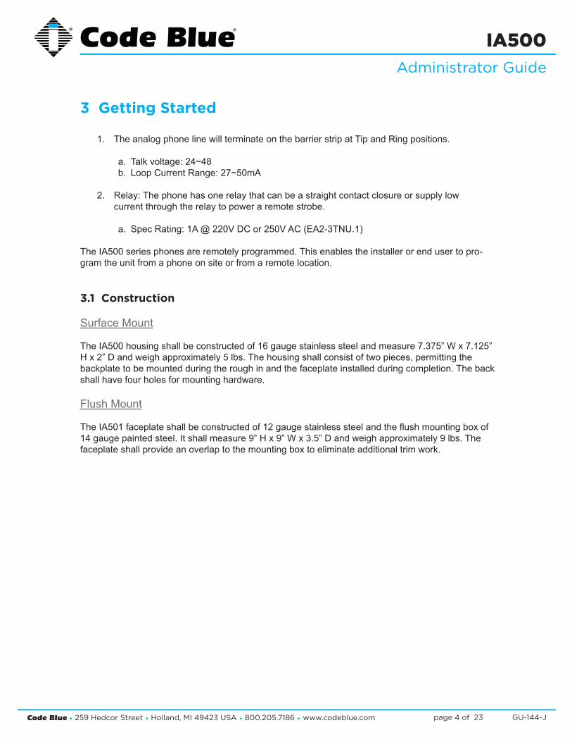
3 Getting Started
1. The analog phone line will terminate on the barrier strip at Tip and Ring positions.
a. Talk voltage: 24~48 b. Loop Current Range: 27~50mA
2. Relay: The phone has one relay that can be a straight contact closure or supply low current through the relay to power a remote strobe.
a. Spec Rating: 1A @ 220V DC or 250V AC (EA2-3TNU.1)
The IA500 series phones are remotely programmed. This enables the installer or end user to pro-gram the unit from a phone on site or from a remote location.
3.1 Construction
Surface Mount
The IA500 housing shall be constructed of 16 gauge stainless steel and measure 7.375” W x 7.125” H x 2” D and weigh approximately 5 lbs. The housing shall consist of two pieces, permitting the backplate to be mounted during the rough in and the faceplate installed during completion. The back shall have four holes for mounting hardware.
Flush Mount
The IA501 faceplate shall be constructed of 12 gauge stainless steel and the flush mounting box of 14 gauge painted steel. It shall measure 9” H x 9” W x 3.5” D and weigh approximately 9 lbs. The faceplate shall provide an overlap to the mounting box to eliminate additional trim work.
Code Blue • 259 Hedcor Street • Holland, MI 49423 USA • 800.205.7186 • www.codeblue.com GU-144-Jpage 5 of 23
IA500Administrator Guide
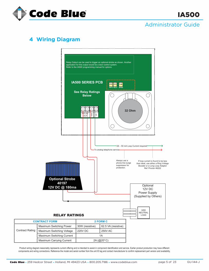
4 Wiring Diagram
IA500 SERIES PCB
RELAYOUT
RN
G
TIP
Relay Output can be used to trigger an optional strobe as shown. Anotherapplication for this output would be a door control system.Refer to the IA500 programming manual for options.
See Relay RatingsBelow
INFO SPKRHELP
32 Ohm
Optional12V DC
Power Supply(Supplied by Others)
GRDNEUTRAL
LOAD
Always use a phone line surgesuppressor forprotection.
28 – 50 mA Loop Current required
To analog telephone service
If loop current is found to be lessthan ideal, use either a Ring Voltage
Booster or a Long Loop AdaptorRef: Proctor 46222
Optional Strobe40197
12V DC @ 180ma
Product wiring diagram reasonably represents current offering and is intended to assist in component identification and service. Earlier product production may have different components and wiring connections. Reference the model and serial number from the unit ID tag and contact manufacturer to confirm replacement part version and availability.
CONTRACT FORM 2 FORM C
Contract RatingMaximum Switching Power 30W (resistive) 62.5 VA (resistive)
Maximum Switching Voltage 220V DC 250V AC
Maximum Switching Current 1A
Maximum Carrying Current 2A (@200 C)
RELAY RATINGS

Code Blue • 259 Hedcor Street • Holland, MI 49423 USA • 800.205.7186 • www.codeblue.com GU-144-Jpage 6 of 23
IA500Administrator Guide
5 Installation The IA500 Series comes in surface and flush mount options. The surface mount allows the mounting bracket to be installed during rough in and the faceplate with electronics during completion. The faceplate on the flush mount is five inches square and provides an overlap to the mounting box to eliminate additional trim work.
5.1 IA500
7.00
in.
7 1/4"
3/16"
1 5/16
4 1/4
Ø 1/2"
Three ½-inch conduit openings are available
through thebottom of this panel
1 1/2"
5 3/4
3.72 4 7/
8"
REQUIRED MATERIALS
• Cat 3 shield twisted phone wire• 4 - #8 screw (fasteners)
• To install the IA500, first remove the two retaining screws (Allen wrench provided), from each side of the case.
• Remove the rear mounting plate by sliding it downward.
• Using the mounting plate as your guide on the wall, mark the mounting hole and conduit hole locations on the wall.
• Remove the rear mounting plate and create the required holes, along with any conduit you choose to use. Attach rear mounting plate to wall.
• Pull CAT 3 shield twisted pair wire through the conduit opening in the rear mounting plate, and leave nine inches of CAT 3 wire beyond the wall.
• Strip the tip and ring wires and attach them to the IA500 (PCB) screw terminals marked tip and ring.
• Slide the IA500 down, starting from the top of the rear mounting plate until the bottom of the IA500 comes flush with the rear mounting plate lip.
• Replace the two retaining screws.
Code Blue • 259 Hedcor Street • Holland, MI 49423 USA • 800.205.7186 • www.codeblue.com GU-144-Jpage 7 of 23
IA500Administrator Guide
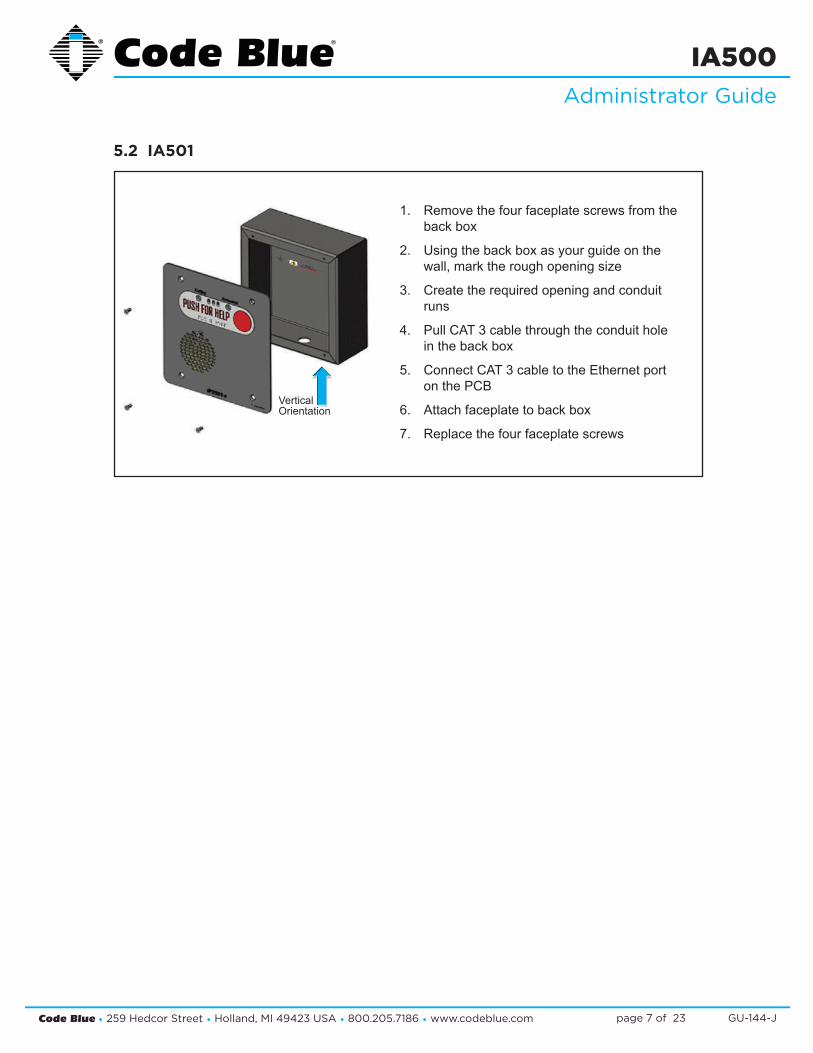
1. Remove the four faceplate screws from the back box
2. Using the back box as your guide on the wall, mark the rough opening size
3. Create the required opening and conduit runs
4. Pull CAT 3 cable through the conduit hole in the back box
5. Connect CAT 3 cable to the Ethernet port on the PCB
6. Attach faceplate to back box
7. Replace the four faceplate screws
VerticalOrientation
5.2 IA501
Code Blue • 259 Hedcor Street • Holland, MI 49423 USA • 800.205.7186 • www.codeblue.com GU-144-Jpage 8 of 23
IA500Administrator Guide
6 CB 5 Series Curb Mount Installation Instructions
1.0 PRE-INSTALLATION
Electrical Preparation – The unit will need a phone wire (POTS) run through the curb mount with at least 10 inches of wire coming out of the top of the curb mount to connect to the Code Blue phone. A 1/2 inch conduit hole in the back of the unit has been provided for this purpose.
2.0 INSTALLATION PROCEDURES – Curb Mounts should be mounted on concrete bases with a depth of 4-5 inches, using the correct mounting bolts for your application.
Mounting Holes – In order to comply with the Americans with Disabilities Act (ADA) of 1990, the speakerphone button(s) should be positioned between 34 and 48 inches from grade level (Consult an ADA specialist in your area to verify local and federal guidelines).
Secure the housing to the Curb Mount – Four bolts with 4 lock nuts,4 rubber washers and 8 steel washers are provided to securely fasten the housing to the curb mount. Connect communications wiring. Follow all federal and local codes that apply.
See diagrams next page

Code Blue • 259 Hedcor Street • Holland, MI 49423 USA • 800.205.7186 • www.codeblue.com GU-144-Jpage 9 of 23
IA500Administrator Guide
Specifications subject to change without notice or obligation on the part of the manufacturer.

Code Blue • 259 Hedcor Street • Holland, MI 49423 USA • 800.205.7186 • www.codeblue.com GU-144-Jpage 10 of 23
IA500Administrator Guide
7 ProgrammingThe IA500 series can be programmed from any touch-tone telephone keypad or through the use of Code Blue’s Unit Programming & Diagnostics (UPD) software. There are basically two modes of operation: Monitoring and Programming. Programming is broken down into two categories: Basic and Audio.
Either the first number or first two numbers is the actual “command,” followed by the default pass-word. The # (pound symbol) is always your enter key and the * # (asterisk and pound symbols) end a programming or monitoring session, as well as invoke a force hang-up. As an example, enter Programming Mode by dialing: 2 - 2258 - #.
Anytime you wish to reset programming, use Command 99 - #.
NOTE: If programming the IA500 for ring down or hotline service, you must enter 99 - # to clear the factory default settings.
In some installations you may find the phone will not answer when called and the phone line you’re using goes into reorder tones. This is an indication the line current is below minimum to ring the phone. If this is the case, do the following:
• Locate the jumper on the bottom of the PCB board below the barrier strip. • Remove the jumper (shunt).• The IA500 will now answer the incoming call.
Low line current comes at an expense as the phone cannot roll over to the next number. If calling into the unit is more important than roll-over dialing, the shunt can remain off. Available options:
1. Shunt Applied: Normal operation with a strong POTS line service; unit will answer and also roll over normally.
2. Shunt Removed: Operations are limited; able to answer an incoming call, but unable to roll over.
3. Shunt Applied w/Long Loop Adapter Applied to the Line: Normal operations; receiving and placing calls are as expected (reference Proctor Long Loop Adapter).
Code Blue • 259 Hedcor Street • Holland, MI 49423 USA • 800.205.7186 • www.codeblue.com GU-144-Jpage 11 of 23
IA500Administrator Guide
7.1 General Programming
To program an IA500 series phone you need to use an analog phone or an IP phone that pushes DTMF tones and call the extension or phone number of the Emergency phone. When you dial the phone number to the Code Blue speakerphone you’re trying to reach, you will hear an acknowl-edgement tone or RFA tone to let you know that the phone has picked up and is ready to be pro-grammed. Press the programming password for that particular model phone to enter programming mode and configure the phone.
For example, to program an IA500:
Call into the speakerphone or “call box.” After the beep, press 22258#. Wait for acknowledgement tone, press 1-1 <phone number> #. Wait for acknowledgement tone, then press * # to hang up.
7.2 Basic Programming Mode
Assigning Telephone Numbers to the Help and Info Buttons:
1. Call the IA500 by dialing its assigned phone number or extension.
2. Upon answering, the unit will emit a short beep.
3. The unit automatically enters Monitoring Mode (see previous page).
4. You have two minutes to select Basic Programming or Audio Programming Mode, as well as the option to issue additional commands during this interim, such as Reset programming (see Figure 1 on the following page) .
5. To enter into Basic Programming Mode, dial the unit’s default password, 2 - 2258 - #
NOTE: If the initial password (i.e., 2258) was changed by another operator, then the new password must be entered.
a. The unit will emit a single beep; an incorrect entry will trigger a triple beep.
6. Input telephone numbers based on emergency buttons.
a. There are three “fields” or three sets of numbers that encompass what phone number will be dialed and in which sequence:
• Assigned Button Number - The first digit will be either a “1” or “2”, corresponding to the Help or Info button (“2” is only used with the 500-d and 501-d models).
• Call Sequence - Represents the order in which the stored number will be dialed.
• Phone Number - Designates the actual phone number to be dialed; 1 to 16 digits available. The asterisk (*) can be used for a pause.
• Programming sequence - each line entry is completed by entering the pound sign (#).
(Continued on next page)

Code Blue • 259 Hedcor Street • Holland, MI 49423 USA • 800.205.7186 • www.codeblue.com GU-144-Jpage 12 of 23
IA500Administrator Guide
Command Default Description Example
2 2258 Enter Programming Mode 2-2258-#8 2258 Enter Audio Programming Mode 8-2258-#99 - Reset Programming 99-## - Enter (i.e.Initiate; used at the end of
EVERY command)(see “#” in each example above)
Ý# - Force hang up (phone disconnects) Ý-#
b. Figure 2 (below) depicts the three fields, categories listed in red, followed by the pound sign (#) required for programming the IA500. In addition, this chart provides actual examples of a phone configuration.
c. Sequence of Calls:
• In the sample provided (Figure 2), when the Red button (i.e., PUSH FOR HELP) is pushed, the phone will dial the first number – 1111. If this number happens to be busy or is not answered within the time set (i.e., Command 04 - Ring Time; Figure 3) the phone will hang up and dial the next number assigned to the Red button. The unit will cycle through to the last number in memory for the HELP button (i.e., 1-6-9-231-555-1212-#). The unit will cycle through the number twice since the default is set to 2 (Command 05, Figure 3).
NOTE: In this case, the first digit reflects that the Red button (1) has been assigned to the sixth memory location (6) and further, the phone must first dial a “9” to initiate the call. The regular phone number, beginning with area code, follows.
d. Programming Sample 1:
• Using the PHONE NUMBER CONFIGURATION SAMPLE (Figure 2), the Black but-ton (2) has been assigned the third (3) Memory Location for calling extension 2222.
• Although it is the third number programmed into memory, it will be the FIRST number dialed for any user activating the INFO button (i.e., Black button).
7. Once all phone numbers have been allocated into memory, the operator can modify any combination of the settings once in progamming mode:
a. Enter * # (asterisk and pound signs) to close all IA500 programming (Figure 1).
Figure 1

Code Blue • 259 Hedcor Street • Holland, MI 49423 USA • 800.205.7186 • www.codeblue.com GU-144-Jpage 13 of 23
IA500Administrator Guide
Programming Examples
7.3 Additional Programming Commands
1. If not already in programming mode, call the IA500 by dialing its assigned phone number or extension.
2. Upon answering, the unit will emit a short beep.
3. The unit automatically enters Monitoring Mode.
4. You have two minutes to select Basic Programming Mode.
5. Dial 2 - 2258 - # to enter into Basic Programming Mode.
a. As described in the chart below (Figure 3), command options include Call Length, Ring Timer and Calling Cycle, among others.
6. If the command is programmed correctly the unit will emit a single beep; an incorrect entry will trigger a triple beep.
7. Dial 99 - # to reset all programming functions (Figure 1).
(Continued on next page)
ButtonAssignments
Memory Slot
PhoneNumber
Examples while in Programming
Button AssignmentVariations
1 (RED button)
1 123-456-7890 1- 1-1234567890- # RED Button, first assignment
1 (RED button)
2 987-123-4567 1- 2-9871234567- # RED Button, second assignment
1 (RED button)
3 876-543-2109 1- 3-8765432109- # RED Button, third assignment
2 (BLACK button)
4 765-432-1098 2- 4-7654321098- # BLACK Button, first assignment
2 (BLACK button)
5 654-321-0987 2- 5-6543210987- # BLACK Button, second assignment
2 (BLACK button)
6 543-210-9876 2- 6-5432109876- # BLACK Button, third assignment
Figure 2
Code Blue • 259 Hedcor Street • Holland, MI 49423 USA • 800.205.7186 • www.codeblue.com GU-144-Jpage 14 of 23
IA500Administrator Guide
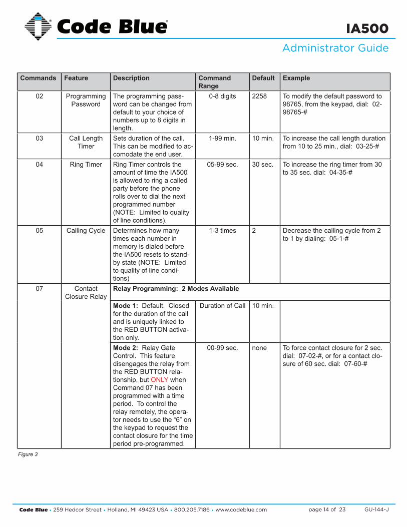
Commands Feature Description CommandRange
Default Example
02 ProgrammingPassword
The programming pass-word can be changed from default to your choice of numbers up to 8 digits in length.
0-8 digits 2258 To modify the default password to 98765, from the keypad, dial: 02-98765-#
03 Call LengthTimer
Sets duration of the call. This can be modified to ac-comodate the end user.
1-99 min. 10 min. To increase the call length duration from 10 to 25 min., dial: 03-25-#
04 Ring Timer Ring Timer controls the amount of time the IA500 is allowed to ring a called party before the phone rolls over to dial the next programmed number (NOTE: Limited to quality of line conditions).
05-99 sec. 30 sec. To increase the ring timer from 30 to 35 sec. dial: 04-35-#
05 Calling Cycle Determines how many times each number in memory is dialed before the IA500 resets to stand-by state (NOTE: Limited to quality of line condi-tions)
1-3 times 2 Decrease the calling cycle from 2 to 1 by dialing: 05-1-#
07 ContactClosure Relay
Relay Programming: 2 Modes Available
Mode 1: Default. Closed for the duration of the call and is uniquely linked to the RED BUTTON activa-tion only.
Duration of Call 10 min.
Mode 2: Relay Gate Control. This feature disengages the relay from the RED BUTTON rela-tionship, but ONLY when Command 07 has been programmed with a time period. To control the relay remotely, the opera-tor needs to use the “6” on the keypad to request the contact closure for the time period pre-programmed.
00-99 sec. none To force contact closure for 2 sec. dial: 07-02-#, or for a contact clo-sure of 60 sec. dial: 07-60-#
Figure 3

Code Blue • 259 Hedcor Street • Holland, MI 49423 USA • 800.205.7186 • www.codeblue.com GU-144-Jpage 15 of 23
IA500Administrator Guide
8 Audio Programming ModeAudio programming is normally performed once all other programming has been completed. These commands allow the installer/programmer to fine tune the IA500’s audio settings to maximize the performance of the attached phone line services.
Field audio programming can have a negative effect on the performance of the IA500 if the person implementing these changes is not thoroughly familiar with telecommunication systems.
NOTE: All changes can easily be reversed by using 99 - # at any time during the AUDIO PRO-GRAMMING MODE session (i.e., 99 - # resets all programming modifications back to factory default settings).
1. Call the IA500 by dialing its assigned phone number or extension.
2. Upon answering, the unit will emit a short beep.
3. The unit automatically enters Monitoring Mode.
4. You have two minutes to initiate Audio Programming Mode.
5. Dial 8 - 2258 - # to enter into live monitoring mode.
a. As described in the chart on page 14 (Figure 4), command options include Speaker Level, Microphone Sensitivity and Background Noise Filter, among others.
6. If the programming command is correct the unit will emit a single beep; an incorrect entry will trigger a triple beep.
7. To close the programming session or to disconnect from the IA500, dial * # (Figure 1).
Command Description Command Range Default Example81 Speaker Output Level 00-15 07 Lower the Speaker Level from 07
to 03 by dialing: 81-03-#82 Microphone Sensitivity 00-15 07 To decrease the Microphone Sen-
sitivity from 07 to 03, dial: 82-03-#83 Phone Line Receive
Gain00-15 02 Increase the Phone Line Receive
Gain from 02 to 05 by dialing: 83-05-#
87 Background Noise Filter
1 = On2 = Off
2 To turn on the Background Noise Filter from 2 to 1, dial: 87-1-#
Filter Delay Speed 3 = no delay4 = 10ms delay
3 Remove any Filter Delay Speed by dialing: 87-3-#Add a 10ms Delay by dialing: 87-4-#
Figure 4

Code Blue • 259 Hedcor Street • Holland, MI 49423 USA • 800.205.7186 • www.codeblue.com GU-144-Jpage 16 of 23
IA500Administrator Guide
8.1 Audio Program Effects
Due to variation in telephone line voltage and loop current, changes will affect the quality of sound from and to the IA500. Code Blue has attempted to provide a configuration to match a majority of normal installations. However, manual changes may be required to achieve the best performance.
1. Broken Audio
a. Discontinuous audio signal between operator and user is normally related to over- sensitivity of the microphone.
b. Dial 82 - 02 - # to decrease the Microphone Sensitivity and continue to modify as necessary (option range is 00-15; Figure 4).
2. Speaker Volume Too Low
a. Increase the Speaker Output Level by changing Command 81 to 81 - 12 - # (option range is 00-15; Figure 4).
3. NOTE: If the phone line is weak this command change may produce a negative condition.
4. Phone Line Receive Gain
a. Occasionally, when the phone line is below standard gain levels it is necessary to change the IA500’s line gain control. Changing program settings in this area can affect both speaker and microphone performance (i.e, there could be negative impacts upon previously made IA500 settings).
b. To modify the default setting, dial 83 - (enter new value, between 01 and 15) - # (Figure 4).

Code Blue • 259 Hedcor Street • Holland, MI 49423 USA • 800.205.7186 • www.codeblue.com GU-144-Jpage 17 of 23
IA500Administrator Guide
9 Auxiliary Relay 1 Output using Command 6The IA500 has only one command available during a call. This command enables the Auxiliary Re-lay to change from activating with the Red Button to activation when the operator enters 6 (Figure 5) from the keypad.
NOTE: Auxiliary 1 can only perform one of the following functions:
a. Closed for the duration of the call (default setting).
b. Operator-dependent during the call for the time period set with pre-programmed Command 07 (Figure 4).
1. If not already in programming mode, call the IA500 by dialing its assigned phone number or extension.
2. Upon answering, the unit will emit a short beep.
3. The unit automatically enters Monitoring Mode.
4. You have two minutes to initiate Basic Programming Mode.
5. Dial 2 - 2258 - #, or appropriate password, to enter into programming mode.
6. Modify the Contact Closure Relay by dialing 07 - xx - #, where “xx” equals the duration of the closed relay (option range is 00-99 seconds; Figure 4).
7. Close the programming session by dialing * # (Figure 1).
8. During a call, the operator enters 6 on their keypad and the auxiliary relay closes for the time period set (as described in Step 6) and then releases.
Command Description Command Range Default Example6 Turns on Auxiliary
Output00-99 seconds Enter 6 from phone keypad
Figure 5

Code Blue • 259 Hedcor Street • Holland, MI 49423 USA • 800.205.7186 • www.codeblue.com GU-144-Jpage 18 of 23
IA500Administrator Guide
10 Remote Mount Beacon/Strobe Installation
1.0 ATTACH J-BOX TO THE POLE
1.1 Thread the banding (B) through the pole bracket (A) located on the backside of the J-box (C).
1.2 Wrap the banding around the pole. Cut the banding to desired length.
1.3 Using a screwdriver or nut driver, tighten the banding and make sure that the unit is in the desired location.
NOTE: J-box must be positioned so weep hole faces down.
2.0 ATTACH LIGHT TO BRACKET
3.1 Using the three M4 X 8 screws enclosed (K), fasten the strobe (J) to the round portion of the strobe bracket.
NOTE: If the beacon/strobe is mounted upside-down, a drain hole must be drilled into the lens to prevent it from filling with water.
3.0 ATTACH LIGHT AND BRACKET TO THE J-BOX
4.1 Connect all wiring from the strobe to the wiring from the unit inside of the J-box using wire nuts.
4.2 Attach strobe bracket to the J-box using four 6-32 X ½ screws as shown.
All wiring must be installed and connected by experienced and certified personnel to meet local and national electrical codes, and will include a service disconnect.
A - pole-bracket B - banding C - J-box D - pole-bracket mount nut (4 each)E - pole-bracket mount screw (4 each)F - conduit plugH - strobe-bracket I - 6-32 X ½ screws (4 each)J - strobe lightK - M4 X 8 screws (3 each) (Low voltage)K - 10-24 X ¾ screws (2 each) (High voltage)
Code Blue • 259 Hedcor Street • Holland, MI 49423 USA • 800.205.7186 • www.codeblue.com GU-144-Jpage 19 of 23
IA500Administrator Guide
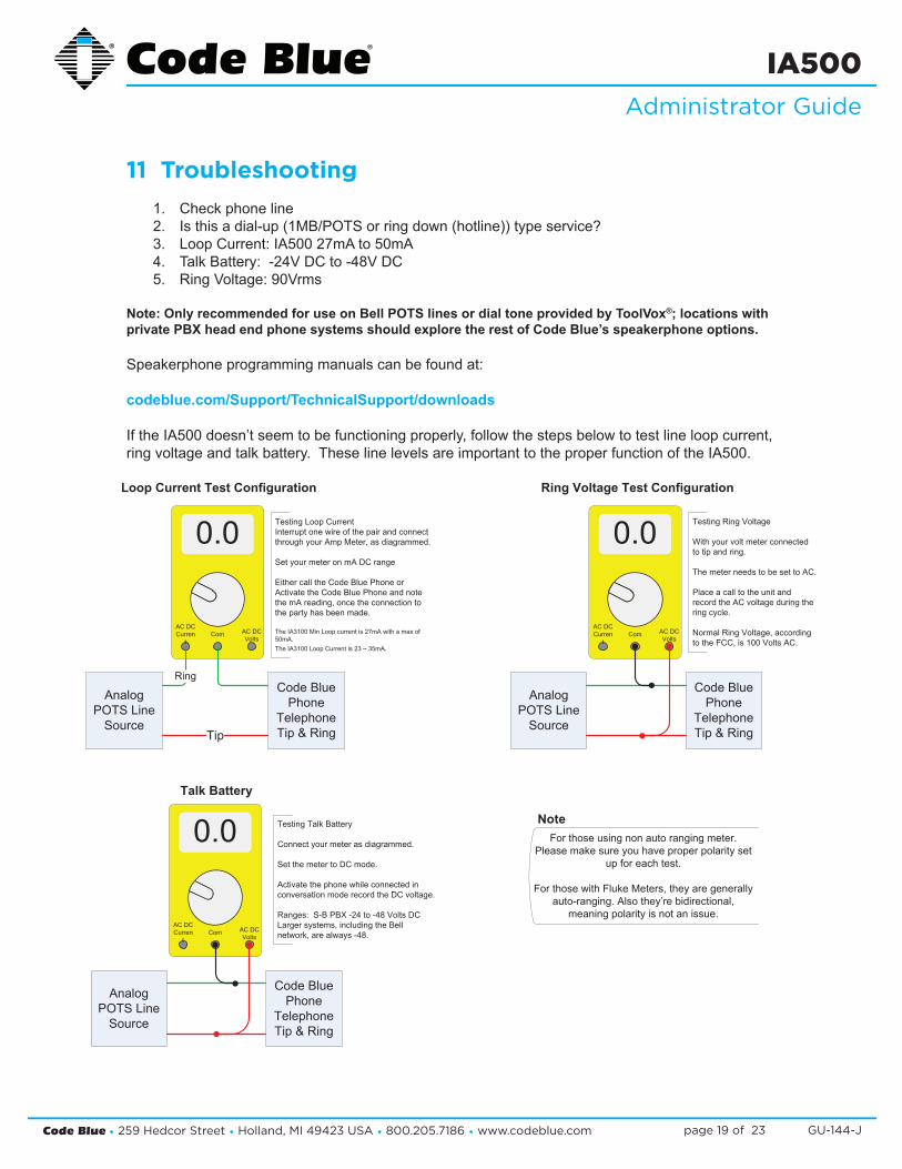
11 Troubleshooting1. Check phone line2. Is this a dial-up (1MB/POTS or ring down (hotline)) type service?3. Loop Current: IA500 27mA to 50mA4. Talk Battery: -24V DC to -48V DC5. Ring Voltage: 90Vrms
Note: Only recommended for use on Bell POTS lines or dial tone provided by ToolVox®; locations with private PBX head end phone systems should explore the rest of Code Blue’s speakerphone options.
Speakerphone programming manuals can be found at:
codeblue.com/Support/TechnicalSupport/downloads
If the IA500 doesn’t seem to be functioning properly, follow the steps below to test line loop current, ring voltage and talk battery. These line levels are important to the proper function of the IA500.
For those using non auto ranging meter.Please make sure you have proper polarity set
up for each test.
For those with Fluke Meters, they are generallyauto-ranging. Also they’re bidirectional,
meaning polarity is not an issue.
Note
0.0
AC DCCurren
tCom AC DC
Volts
Code BluePhone
TelephoneTip & Ring
AnalogPOTS Line
SourceTip
Ring
Testing Loop CurrentInterrupt one wire of the pair and connectthrough your Amp Meter, as diagrammed.
Set your meter on mA DC range
Either call the Code Blue Phone orActivate the Code Blue Phone and notethe mA reading, once the connection tothe party has been made.
The IA3100 Min Loop current is 27mA with a max of50mA.The IA3100 Loop Current is 23 – 35mA.
0.0
AC DCCurren
tCom AC DC
Volts
Code BluePhone
TelephoneTip & Ring
AnalogPOTS Line
Source
Testing Ring Voltage
With your volt meter connectedto tip and ring.
The meter needs to be set to AC.
Place a call to the unit andrecord the AC voltage during thering cycle.
Normal Ring Voltage, accordingto the FCC, is 100 Volts AC.
0.0
AC DCCurren
tCom AC DC
Volts
Code BluePhone
TelephoneTip & Ring
AnalogPOTS Line
Source
Testing Talk Battery
Connect your meter as diagrammed.
Set the meter to DC mode.
Activate the phone while connected inconversation mode record the DC voltage.
Ranges: S-B PBX -24 to -48 Volts DCLarger systems, including the Bellnetwork, are always -48.
Loop Current Test Configuration Ring Voltage Test Configuration
Talk Battery

Code Blue • 259 Hedcor Street • Holland, MI 49423 USA • 800.205.7186 • www.codeblue.com GU-144-Jpage 20 of 23
IA500Administrator Guide
12 Technical Specifications
Note: Only recommended for use on Bell POTS lines or dial tone provided by ToolVox®; locations with private PBX head end phone systems should explore the rest of Code Blue’s speakerphone options.
Telephone & elecTronic inTerface
Ringer Equivalence Num-ber
FCC REN AC = 0.1 DC = 0.25
Surge Suppressors Telephone interface FCC part 68 Approved
Signaling DTMF (tone)Loop Current 27-50 mAAuxiliary Output Dry contact relay 120mA maxi-
mum. Normally open relay. Form C.
System Connections Individual phone lines or PBX extensions recommended
environmenTal
Operating Tempera-ture Range
-220 to 1500 F
Operating Relative Humidity
0% to 95% RHNon-condensing
Electrostatic Dis-charge
20kV
Faceplate Stainless steel, piezoelectric weatherproof button, microphone and speaker openings reduce damage from vandalism, waterproof 3½" speaker, waterproof microphone
physical
Dimensions (face-plate)
IA 500 7⅜" w x 7⅛" h x 2" d 16 Gauge Stainless SteelIA 501 9" w x 9" h x 3½" d 12 Gauge Stainless Steel Faceplate 14 Gauge Painted Steel Backbox 8¼" w x 8¼" h
Remote Mount Electronics
Speakerphone electronics are conformal coated to withstand harsh environmental conditions.
InterAct 500-sSingle ButtonSurface Mount
InterAct 500-dDual Button
Surface Mount
InterAct 501-dDual Button Flush Mount
InterAct 501-sSingle ButtonFlush Mount

Code Blue • 259 Hedcor Street • Holland, MI 49423 USA • 800.205.7186 • www.codeblue.com GU-144-Jpage 21 of 23
IA500Administrator Guide
13 Maintenance Schedule
Perform functional communications check Action: Press red button
Strobe activates Red LED “Call Placed” light turns on Message plays Call connects, green LED “Call Received” light turns on Confirm conversation clarity with dispatch
Visually check lighting functions: Faceplate light Beacon Strobe
Visually inspect unit for damage to: Faceplate Piezo button Microphone (pest infestation, damage or obstructions) Speaker (pest infestation, damage or obstructions)
Check batteries Functioning with full charge Recharging fully, including NightCharge®/Solar units (NOTE: recommend mid- to late afternoon inspection)
Remove access door and faceplate assembly to inspect the following: Ensure all electrical connections are secure Check all phone connections for corrosion (If corroded, clean and coat with dielectric gel or replace) Ensure all battery connections are tight and clean Verify no stains exist around gasket areas (Stains indicate leaking and gasket should be replaced) Verify moisture weep hole on cabinet bottom is open and unobstructed
Verify bottom of bollards are at least 1/2 inch above footing and free of obstructions (Only applies to CB 1, CB 5 and CB 9 units)
Apply automotive paint sealant to unit exterior for protecting finish against environmental pollutants (Suggested products include Black Magic Wet Shine Liquid Wax, Nu Finish NFP-80, and 5 Star Shine )
Clean and coat exterior stainless steel cabinets with cleaner/polish (Suggested products include Chase Products' Champion Sprayon Stainless Steel Cleaner to help protect finish against environmental pollutants)
Visually confirm line-of-sight is still clear to base station (i.e., confirm that new tree growth, new building construction or other obstructions are not blocking view of base station)
Replace batteries used with NightCharge®, cellular or RF systems (Replace with batteries recommended by the communication manufacturer to ensure optimal performance)
Guard tasks Technician tasks
LEGEND
G
BIANNUALLY
MONTHLY OR QUARTERLY
DAILY OR WEEKLY
G T
G
G
G
T
T
G
T
T
ANNUALLY
Code Blue • 259 Hedcor Street • Holland, MI 49423 USA • 800.205.7186 • www.codeblue.com GU-144-Jpage 22 of 23
IA500Administrator Guide
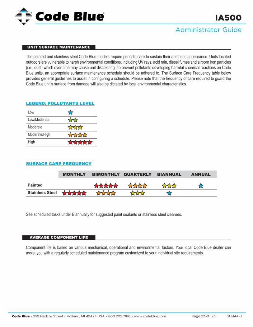
MONTHLY BIMONTHLY QUARTERLY BIANNUAL ANNUAL
Painted êêêêê êêêê êêê êStainless Steel êêêêê êêêê êêê ê
The painted and stainless steel Code Blue models require periodic care to sustain their aesthetic appearance. Units located outdoors are vulnerable to harsh environmental conditions, including UV rays, acid rain, diesel fumes and airborn iron particles (i.e., dust) which over time may cause unit discoloring. To prevent pollutants developing harmful chemical reactions on Code Blue units, an appropriate surface maintenance schedule should be adhered to. The Surface Care Frequency table below provides general guidelines to assist in configuring a schedule. Please note that the frequency of care required to guard the Code Blue unit’s surface from damage will also be dictated by local environmental characteristics.
Low êLow/Moderate êêModerate êêêModerate/High êêêêHigh êêêêê
LEGEND: POLLUTANTS LEVEL
See scheduled tasks under Biannually for suggested paint sealants or stainless steel cleaners.
Component life is based on various mechanical, operational and environmental factors. Your local Code Blue dealer can assist you with a regularly scheduled maintenance program customized to your individual site requirements.
UNIT SURFACE MAINTENANCE
AVERAGE COMPONENT LIFE
SURFACE CARE FREQUENCY
Code Blue • 259 Hedcor Street • Holland, MI 49423 USA • 800.205.7186 • www.codeblue.com GU-144-Jpage 23 of 23
IA500Administrator Guide
14 WarrantyCode Blue Corporation provides a limited warranty on this product. Refer to your sales agreement to establish the terms. In addition, Code Blue’s standard warranty language, as well as information regarding support for this product while under warranty, is available at www.codeblue.com/support.
Notice: Every effort was made to ensure that the information in this document was complete and accurate at the time of printing. Information is subject to change.