
INSTALLATION, SERVICE AND MAINTENANCE … de instruccions...INSTALLATION, SERVICE AND MAINTENANCE...
26
INSTALLATION, SERVICE AND MAINTENANCE INSTRUCTIONS BALL VALVE INOXPA, S.A. c/Telers, 54 Aptdo. 174 E-17820 Banyoles Girona (Spain) Tel. : (34) 972 - 57 52 00 Fax. : (34) 972 - 57 55 02 Email: [email protected] www.inoxpa.com Original Manual 10.100.30.00EN_RevD ED. 2012/10
Transcript of INSTALLATION, SERVICE AND MAINTENANCE … de instruccions...INSTALLATION, SERVICE AND MAINTENANCE...
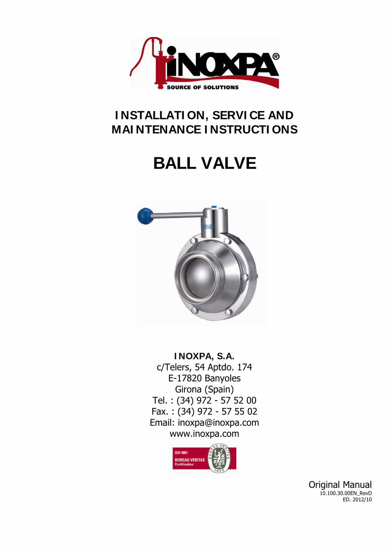
INSTALLATION, SERVICE AND MAINTENANCE INSTRUCTIONS
BALL VALVE
INOXPA, S.A. c/Telers, 54 Aptdo. 174
E-17820 Banyoles Girona (Spain)
Tel. : (34) 972 - 57 52 00 Fax. : (34) 972 - 57 55 02 Email: [email protected]
www.inoxpa.com
Original Manual
10.100.30.00EN_RevD ED. 2012/10
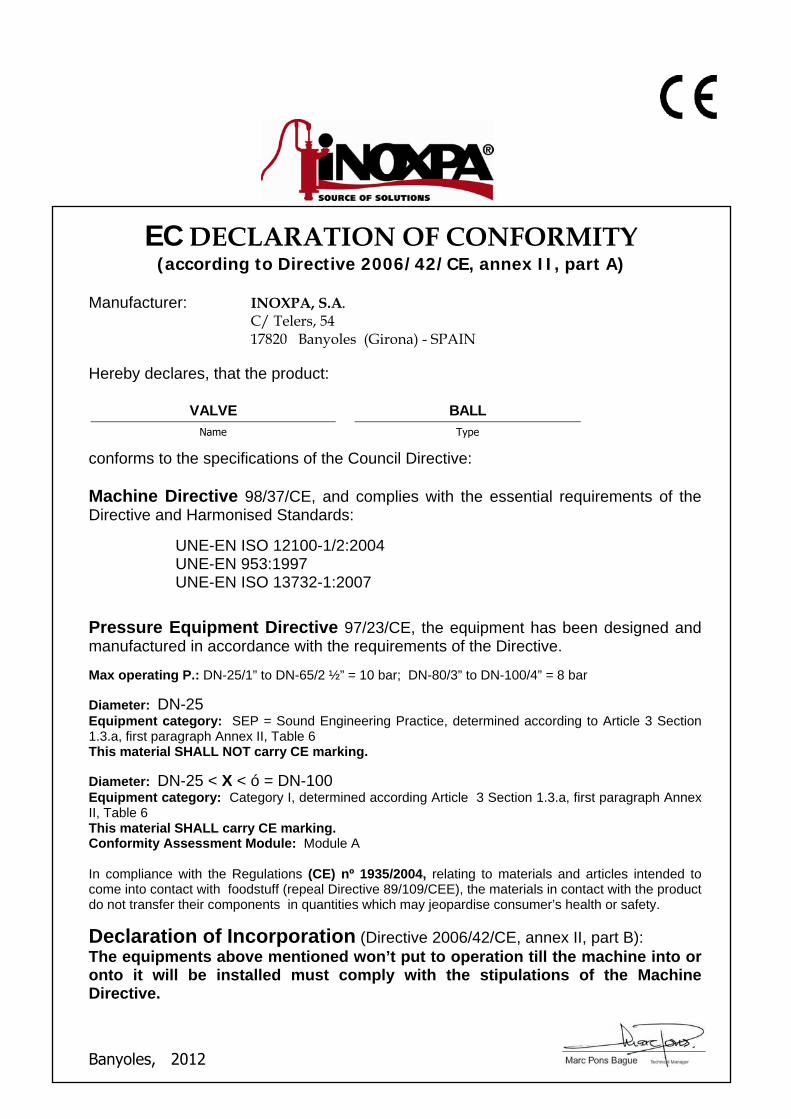
EC DECLARATION OF CONFORMITY (according to Directive 2006/42/CE, annex II, part A)
Manufacturer: INOXPA, S.A.
C/ Telers, 54 17820 Banyoles (Girona) - SPAIN
Hereby declares, that the product:
VALVE BALL
Name Type
conforms to the specifications of the Council Directive: Machine Directive 98/37/CE, and complies with the essential requirements of the Directive and Harmonised Standards:
UNE-EN ISO 12100-1/2:2004 UNE-EN 953:1997 UNE-EN ISO 13732-1:2007
Pressure Equipment Directive 97/23/CE, the equipment has been designed and manufactured in accordance with the requirements of the Directive. Max operating P.: DN-25/1” to DN-65/2 ½” = 10 bar; DN-80/3” to DN-100/4” = 8 bar
Diameter: DN-25 Equipment category: SEP = Sound Engineering Practice, determined according to Article 3 Section 1.3.a, first paragraph Annex II, Table 6 This material SHALL NOT carry CE marking. Diameter: DN-25 < X < ó = DN-100 Equipment category: Category I, determined according Article 3 Section 1.3.a, first paragraph Annex II, Table 6 This material SHALL carry CE marking. Conformity Assessment Module: Module A In compliance with the Regulations (CE) nº 1935/2004, relating to materials and articles intended to come into contact with foodstuff (repeal Directive 89/109/CEE), the materials in contact with the product do not transfer their components in quantities which may jeopardise consumer’s health or safety.
Declaration of Incorporation (Directive 2006/42/CE, annex II, part B): The equipments above mentioned won’t put to operation till the machine into or onto it will be installed must comply with the stipulations of the Machine Directive.
Banyoles, 2012
ED. 2012/10 1.Safety 3
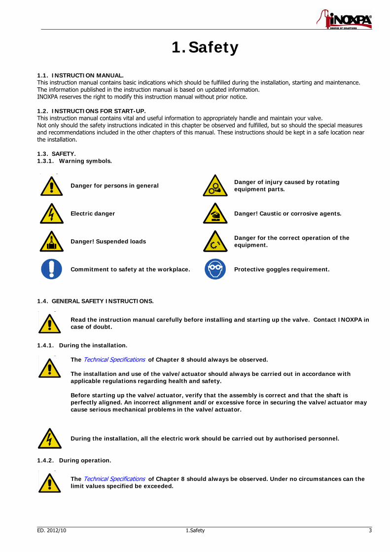
1. Safety 1.1. INSTRUCTION MANUAL. This instruction manual contains basic indications which should be fulfilled during the installation, starting and maintenance. The information published in the instruction manual is based on updated information. INOXPA reserves the right to modify this instruction manual without prior notice. 1.2. INSTRUCTIONS FOR START-UP. This instruction manual contains vital and useful information to appropriately handle and maintain your valve. Not only should the safety instructions indicated in this chapter be observed and fulfilled, but so should the special measures and recommendations included in the other chapters of this manual. These instructions should be kept in a safe location near the installation. 1.3. SAFETY. 1.3.1. Warning symbols.
Danger for persons in general
Danger of injury caused by rotating equipment parts.
Electric danger
Danger! Caustic or corrosive agents.
Danger! Suspended loads
Danger for the correct operation of the equipment.
Commitment to safety at the workplace.
Protective goggles requirement.
1.4. GENERAL SAFETY INSTRUCTIONS.
Read the instruction manual carefully before installing and starting up the valve. Contact INOXPA in case of doubt.
1.4.1. During the installation.
The Technical Specifications of Chapter 8 should always be observed. The installation and use of the valve/actuator should always be carried out in accordance with applicable regulations regarding health and safety. Before starting up the valve/actuator, verify that the assembly is correct and that the shaft is perfectly aligned. An incorrect alignment and/or excessive force in securing the valve/actuator may cause serious mechanical problems in the valve/actuator.
During the installation, all the electric work should be carried out by authorised personnel.
1.4.2. During operation.
The Technical Specifications of Chapter 8 should always be observed. Under no circumstances can the limit values specified be exceeded.
4 1.Safety ED. 2012/10
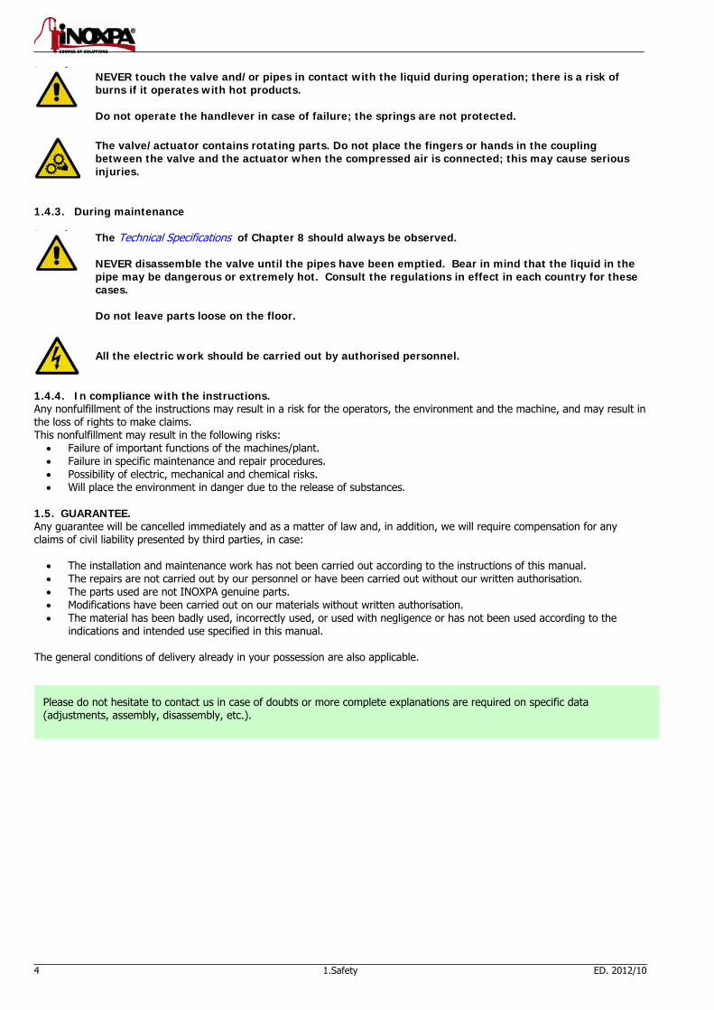
NEVER touch the valve and/or pipes in contact with the liquid during operation; there is a risk of burns if it operates with hot products. Do not operate the handlever in case of failure; the springs are not protected.
The valve/actuator contains rotating parts. Do not place the fingers or hands in the coupling between the valve and the actuator when the compressed air is connected; this may cause serious injuries.
1.4.3. During maintenance
The Technical Specifications of Chapter 8 should always be observed. NEVER disassemble the valve until the pipes have been emptied. Bear in mind that the liquid in the pipe may be dangerous or extremely hot. Consult the regulations in effect in each country for these cases. Do not leave parts loose on the floor.
All the electric work should be carried out by authorised personnel.
1.4.4. In compliance with the instructions. Any nonfulfillment of the instructions may result in a risk for the operators, the environment and the machine, and may result in the loss of rights to make claims. This nonfulfillment may result in the following risks:
Failure of important functions of the machines/plant. Failure in specific maintenance and repair procedures. Possibility of electric, mechanical and chemical risks. Will place the environment in danger due to the release of substances.
1.5. GUARANTEE. Any guarantee will be cancelled immediately and as a matter of law and, in addition, we will require compensation for any claims of civil liability presented by third parties, in case:
The installation and maintenance work has not been carried out according to the instructions of this manual. The repairs are not carried out by our personnel or have been carried out without our written authorisation. The parts used are not INOXPA genuine parts. Modifications have been carried out on our materials without written authorisation. The material has been badly used, incorrectly used, or used with negligence or has not been used according to the
indications and intended use specified in this manual. The general conditions of delivery already in your possession are also applicable.
Please do not hesitate to contact us in case of doubts or more complete explanations are required on specific data (adjustments, assembly, disassembly, etc.).
ED. 2012/10 2.Table of Contents 5
2. Table of Contents
1. Safety
1.1. Instruction manual. .......................................................................................................... 3 1.2. Instructions for start-up. ................................................................................................... 3 1.3. Safety. ............................................................................................................................ 3 1.4. General safety instructions. ............................................................................................... 3 1.5. Guarantee. ...................................................................................................................... 4
2. Table of contents
3. Receiving and installation
3.1. Check shipment ............................................................................................................... 6 3.2. Delivery and unpacking .................................................................................................... 6 3.3. Identification ................................................................................................................... 6 3.4. Location. ......................................................................................................................... 7 3.5. Assembly. ........................................................................................................................ 7 3.6. Checking and inspection. .................................................................................................. 7 3.7. Welding. .......................................................................................................................... 7 3.8. Air connection to actuator ................................................................................................. 9
4. Start-up
4.1. Start-up. ........................................................................................................................ 10 4.2. Operation. ..................................................................................................................... 10
5. Troubleshooting
6. Maintenance
6.1. General information........................................................................................................ 12 6.2. Maintenance. ................................................................................................................. 12 6.3. Cleaning ........................................................................................................................ 13
7. Assembly and disassembly
7.1. Disassembly / Assembly of valve with two-position handlever. .......................................... 15 7.2. Disassembly / Assembly of valve with VERTICAL pneumatic actuator ................................ 16 7.3. Seal assembly. ............................................................................................................... 17 7.4. Actuator assembly options. ............................................................................................. 17 7.5. Valve position. ............................................................................................................... 17
8. Technical specifications
8.1. Technical specifications .................................................................................................. 18 8.2. Manual valve dimensions ................................................................................................ 20 8.3. Dimensions with VERTICAL pneumatic operation ............................................................. 20 8.4. Section and parts list ...................................................................................................... 23 8.5. Parts lists ....................................................................................................................... 23
6 3.Receiving and installation ED. 2012/10
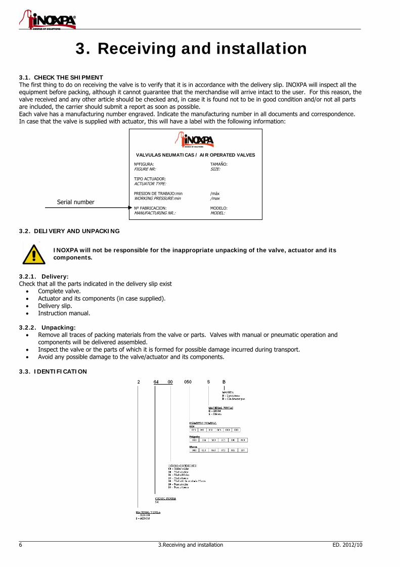
3. Receiving and installation 3.1. CHECK THE SHIPMENT The first thing to do on receiving the valve is to verify that it is in accordance with the delivery slip. INOXPA will inspect all the equipment before packing, although it cannot guarantee that the merchandise will arrive intact to the user. For this reason, the valve received and any other article should be checked and, in case it is found not to be in good condition and/or not all parts are included, the carrier should submit a report as soon as possible. Each valve has a manufacturing number engraved. Indicate the manufacturing number in all documents and correspondence. In case that the valve is supplied with actuator, this will have a label with the following information:
3.2. DELIVERY AND UNPACKING
INOXPA will not be responsible for the inappropriate unpacking of the valve, actuator and its components.
3.2.1. Delivery: Check that all the parts indicated in the delivery slip exist
Complete valve. Actuator and its components (in case supplied). Delivery slip. Instruction manual.
3.2.2. Unpacking:
Remove all traces of packing materials from the valve or parts. Valves with manual or pneumatic operation and components will be delivered assembled.
Inspect the valve or the parts of which it is formed for possible damage incurred during transport. Avoid any possible damage to the valve/actuator and its components.
3.3. IDENTIFICATION
VALVULAS NEUMATICAS / AIR OPERATED VALVES NºFIGURA: TAMAÑO: FIGURE NR: SIZE: TIPO ACTUADOR: ACTUATOR TYPE: PRESION DE TRABAJO:min /máx WORKING PRESSURE:min /max Nº FABRICACION: MODELO: MANUFACTURING NR.: MODEL:
Serial number
ED. 2012/10 3.Receiving and installation 7
The inspector or user will be responsible for the assembly, installation, starting and operation of the valve with or without pneumatic operation.
3.4. LOCATION. This equipment is suitable for his use in food process. Place the valve/actuator in order to facilitate inspections and checks. Leave sufficient space around the valve/actuator for an appropriate inspection, separation and maintenance (See Section 3.7.3). It is very important to be able to access the air-connection device of the actuator, even when in operation. 3.5. ASSEMBLY. Once the location of the valve is defined, the pipe can be connected by welding the bodies of the valve or by means of accessories (connectors). Excessive stress should be avoided during the assembly of the valves and special attention should be given to the following:
Vibration which may be produced in the installation.
Expansion that the pipes may undergo in case hot liquids circulate.
Weight that the pipes can withstand.
Excessive intensity of welding.
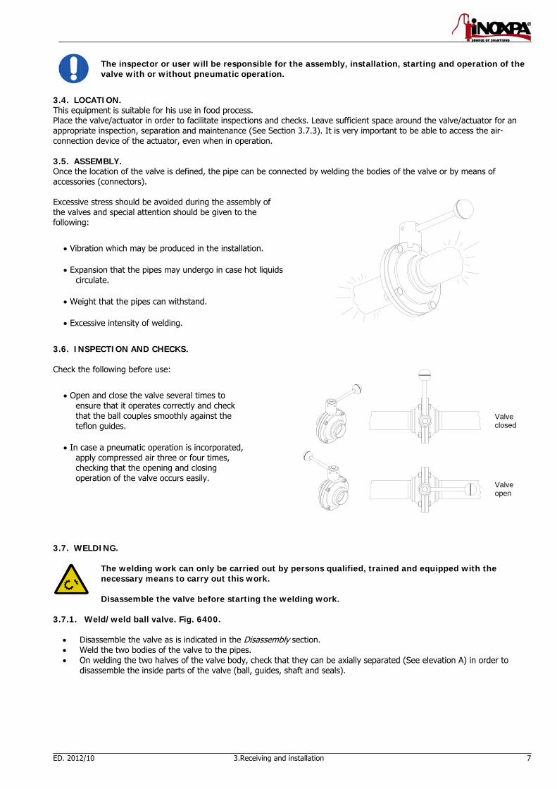
3.6. INSPECTION AND CHECKS. Check the following before use:
Open and close the valve several times to ensure that it operates correctly and check that the ball couples smoothly against the teflon guides.
In case a pneumatic operation is incorporated, apply compressed air three or four times, checking that the opening and closing operation of the valve occurs easily.
3.7. WELDING.
The welding work can only be carried out by persons qualified, trained and equipped with the necessary means to carry out this work. Disassemble the valve before starting the welding work.
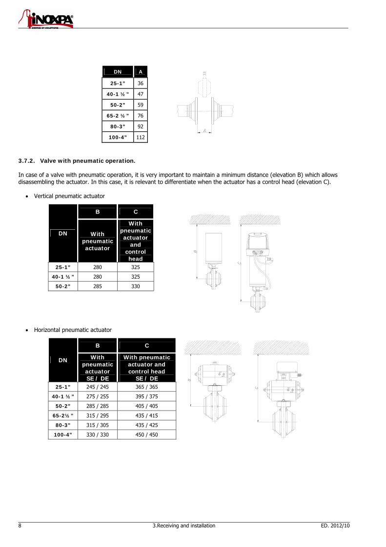
3.7.1. Weld/weld ball valve. Fig. 6400.
Disassemble the valve as is indicated in the Disassembly section. Weld the two bodies of the valve to the pipes. On welding the two halves of the valve body, check that they can be axially separated (See elevation A) in order to
disassemble the inside parts of the valve (ball, guides, shaft and seals).
Valve closed Valve open
8 3.Receiving and installation ED. 2012/10
DN A
25-1” 36
40-1 ½” 47
50-2” 59
65-2 ½” 76
80-3” 92
100-4” 112
3.7.2. Valve with pneumatic operation. In case of a valve with pneumatic operation, it is very important to maintain a minimum distance (elevation B) which allows disassembling the actuator. In this case, it is relevant to differentiate when the actuator has a control head (elevation C).
Vertical pneumatic actuator
DN
B C
With pneumatic actuator
With pneumatic actuator
and control head
25-1” 280 325
40-1 ½” 280 325
50-2” 285 330
Horizontal pneumatic actuator
DN
B C
With pneumatic actuator SE / DE
With pneumatic actuator and control head
SE / DE 25-1” 245 / 245 365 / 365
40-1 ½” 275 / 255 395 / 375
50-2” 285 / 285 405 / 405
65-2½” 315 / 295 435 / 415
80-3” 315 / 305 435 / 425
100-4” 330 / 330 450 / 450

ED. 2012/10 3.Receiving and installation 9
Stainless horizontal pneumatic actuator
DN
B C
With pneumatic actuator SE / DE
With pneumatic actuator and control head
SE / DE 25-1” 245 / 245 365 / 365
40-1 ½” 275 / 255 395 / 375
50-2” 285 / 285 405 / 405
65-2½” 315 / 295 435 / 415
80-3” 315 / 305 435 / 425
100-4” 330 / 330 450 / 450
3.8. AIR CONNECTION TO ACTUATOR.
Connect and check the air connections (BSP 1/8” thread, for vertical and horizontal actuator with stainless coating) according to double- or single-effect needs.
For the horizontal actuator, the air connection should be carried out according to NAMUR/DIN 228/1.
Correctly orientate the actuator and the ball depending on whether an NO/NC actuator is required. One solution or the other can be obtained on turning the ball.
Mind the quality of the compressed air according to the specifications described in chapter 8 Technical Specifications.

10 4.Start-up ED. 2012/10
4. Start-up The start-up of the valve (with or without actuator) can be carried out if the instructions indicated in Chapter 3 – Receiving and Installation are followed. 4.1. START-UP.
Before start-up, the responsible persons should be duly informed of the operation of the valve/actuator and the safety instructions to be followed. This instruction manual should be available to personnel at all times.
The following should be taken into consideration before starting-up the valve/actuator:
Check that the pipe and valve are completely free from possible traces of welding or other foreign matter. Carry out the cleaning of the system if required.
Verify the smooth operation of the valve. If necessary, lubricate with special grease or soapy water. If the valve is supplied with actuator, ensure that the alignment of the valve shaft with the actuator shaft allows for a
smooth operation. Check that the compressed air pressure at the intake to the actuator is that indicated in the Technical Specifications
(Chapter 8). Mind the quality of the compressed air according to the specifications described in chapter 8 Technical Specifications. Control possible leaks and check that all the pipes and connections are watertight and free from leaks. Operate the valve.
4.2. OPERATION.
Do not modify the operating parameters for which the valve/actuator has been designed without written prior authorisation from INOXPA. Do not touch the moving parts of the coupling between the actuator and the valve when the actuator is connected to the compressed air.
¡Danger of burns! Do not touch the valve or pipes when hot liquids are circulating or when cleaning and/or sterilisation are being carried out.
4.2.1. Operation with two-position handlever.
Allows operating the valve manually in the on/off position.
Pull the handlever outward.
Turn the handlever 90º while pulling at the same time.
ED. 2012/10 5.Troubleshooting 11
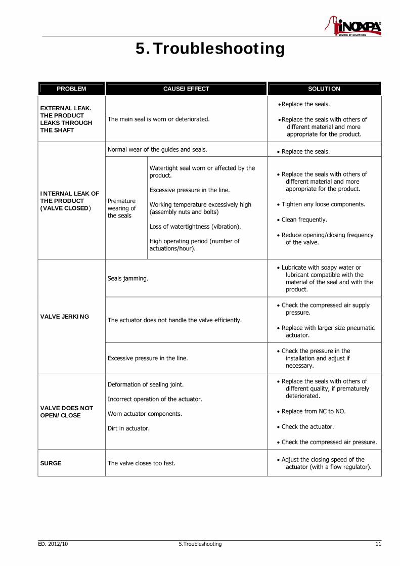
5. Troubleshooting
PROBLEM CAUSE/EFFECT SOLUTION
EXTERNAL LEAK. THE PRODUCT LEAKS THROUGH THE SHAFT
The main seal is worn or deteriorated.
Replace the seals.
Replace the seals with others of different material and more appropriate for the product.
INTERNAL LEAK OF THE PRODUCT (VALVE CLOSED)
Normal wear of the guides and seals. Replace the seals.
Premature wearing of the seals
Watertight seal worn or affected by the product. Excessive pressure in the line. Working temperature excessively high (assembly nuts and bolts) Loss of watertightness (vibration). High operating period (number of actuations/hour).
Replace the seals with others of different material and more appropriate for the product.
Tighten any loose components.
Clean frequently.
Reduce opening/closing frequency of the valve.
VALVE JERKING
Seals jamming.
Lubricate with soapy water or lubricant compatible with the material of the seal and with the product.
The actuator does not handle the valve efficiently.
Check the compressed air supply pressure.
Replace with larger size pneumatic actuator.
Excessive pressure in the line. Check the pressure in the
installation and adjust if necessary.
VALVE DOES NOT OPEN/CLOSE
Deformation of sealing joint. Incorrect operation of the actuator. Worn actuator components. Dirt in actuator.
Replace the seals with others of different quality, if prematurely deteriorated.
Replace from NC to NO.
Check the actuator.
Check the compressed air pressure.
SURGE The valve closes too fast. Adjust the closing speed of the actuator (with a flow regulator).

12 6.Maintenance ED. 2012/10
6. Maintenance 6.1. GENERAL INFORMATION This valve, as well as any other machine, requires maintenance. The instructions contained in this manual cover the identification and replacement of spare parts. The instructions have been prepared for maintenance personnel and for those persons responsible for the supply of spare parts.
Carefully read Chapter 8. Technical Specifications. All replaced material should be duly eliminated/recycled according to the directives in effect in the area. The assembly and disassembly of the valves (with or without pneumatic operation) should only be carried out by qualified personnel. Before beginning the maintenance work, ensure that the compressed air is disconnected and the pipes are not pressured.
6.2. MAINTENANCE. The following is recommended for an appropriate maintenance:
A regular inspection of the valve, of the actuator and its components. Keep a record of the operation of each valve, noting any incident. Always have spare seals in stock.
During maintenance, pay particular attention to the danger indications indicated in this manual.
Do not touch moving parts when the actuator is connected to the compressed air. The valve and pipes should not be pressurised during maintenance. The valve should not be hot during maintenance. ¡Danger of burns! The springs are not protected on disassembling the actuator for reasons of maintenance/repair. For the correct upkeep of the teflon guides, during long periods without operation, the ball should be always be in the closed or open position. Never leave the valve in half operation.
6.2.1. Maintenance of the seals.
REPLACEMENT OF SEALS
Preventive maintenance Replace after twelve (12) months.
Maintenance after a leak Replace at the end of the process.
Scheduled maintenance Regularly check for the absence of leaks and the smooth operation of the valve. Keep a record of the valve. Use statistics to plan inspections.
Lubrication During the assembly, apply lubricants compatible with the material of the seal. See the following table.
SEAL COMPONENT LUBRICANT Class NLGI DIN 51818
NBR/ FPM/ VMQ Klübersynth UH 1 64-2403 3
EPDM/ NBR/ FPM PARALIQ GTE 703 3 The time interval between each preventive maintenance may vary according to the working conditions to which the valve is submitted: Temperature, pressure, number of operations per day, type of cleaning solutions used, etc.

ED. 2012/10 6.Maintenance 13
6.2.2. Storage The storage of the valves should be carried out in an enclosed area, under the following conditions:
Temperature from 15ºC to 30ºC Relative humidity <60%
Storage of the equipment in the open air is NOT allowed. 6.2.3. Spare parts To request spare parts, it is necessary to indicate the type of valve, the position and the description of the part which can be found in the Technical Specification chapter. In case of pneumatic actuators, indicate the type and manufacturing number which are noted in the nameplate and engraved on the body of the valve. 6.3. CLEANING.
The use of aggressive cleaning products such as caustic soda and nitric acid may cause burns to the skin. Use rubber gloves during the cleaning process.
Always use protective goggles.
6.3.1. Automatic CIP (cleaning-in-place) If the valve is installed in a system provided with the CIP process, its disassembly will not be required.
Cleaning solutions for CIP processes. Only use clear water (free from chlorine) to mix with the cleaning agents: a) Alkaline solution: 1% by weight of caustic soda (NaOH) at 70ºC (150ºF) 1 Kg NaOH + 100 l. of water = cleaning solution
o 2.2 l. NaOH at 33% + 100 l. of water = cleaning solution
b) Acid solution: 0.5% by weight of nitric acid (HNO3) at 70ºC (150ºF)
0.7 litres HNO3 at 53% + 100 l. of water = cleaning
Control the concentration of cleaning solutions; it may cause the deterioration of the watertight seals of the valve.
To eliminate the remains of cleaning products, ALWAYS carry out a final rinse on completion of the cleaning process.
Before beginning the disassembly and assembly work, clean the valve inside as well as outside. Disconnect the air from the actuator.
6.3.2. Automatic SIP (sterilization-in-place) The process of sterilization with steam is applied to all the equipment including the pigging.
Do NOT start the equipment during the process of sterilization with steam. The parts/materials suffer no damage if the indications specified in this manual are observed. No cold liquid can enter the equipment till the temperature of the equipment is lower than 60°C (140°F).
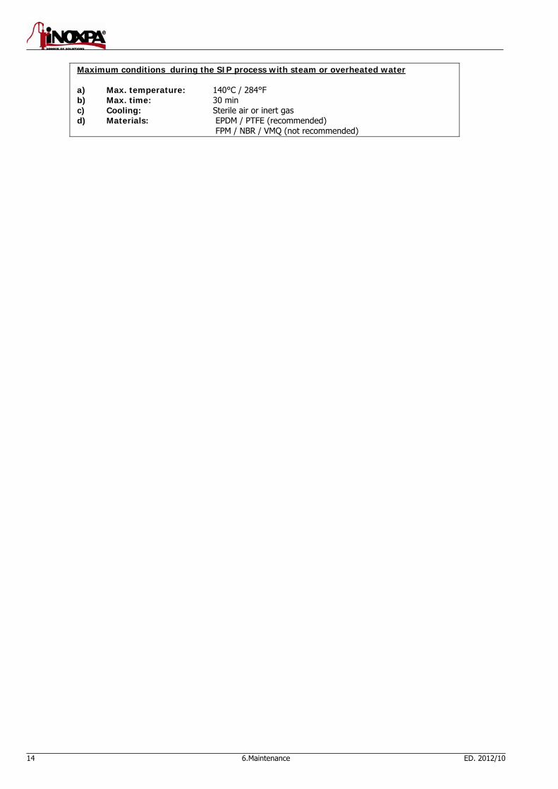
14 6.Maintenance ED. 2012/10
Maximum conditions during the SIP process with steam or overheated water a) Max. temperature: 140°C / 284°F b) Max. time: 30 min c) Cooling: Sterile air or inert gas d) Materials: EPDM / PTFE (recommended) FPM / NBR / VMQ (not recommended)
ED. 2012/10 7.Assembly and disassembly 15
7. Assembly and disassembly
Proceed with caution. There is danger of personal injury. The assembly and disassembly of the valves (with or without pneumatic operation) should only be carried out by qualified personnel.
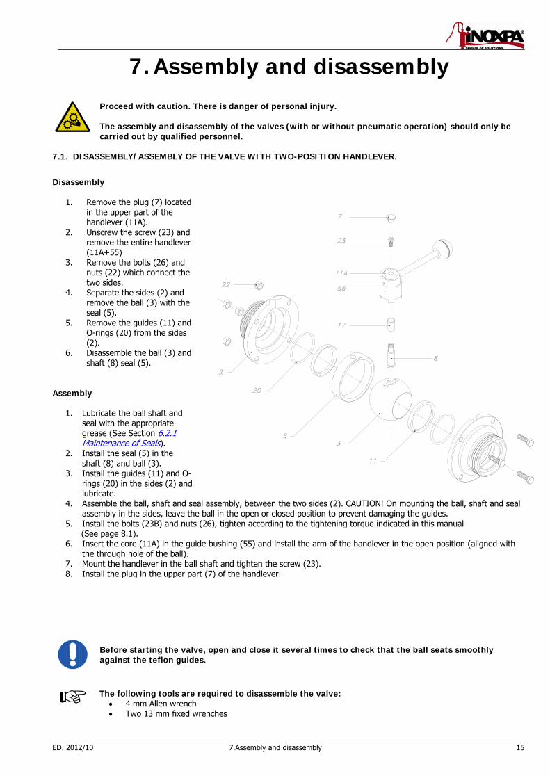
7.1. DISASSEMBLY/ASSEMBLY OF THE VALVE WITH TWO-POSITION HANDLEVER.
Disassembly
1. Remove the plug (7) located in the upper part of the handlever (11A).
2. Unscrew the screw (23) and remove the entire handlever (11A+55)
3. Remove the bolts (26) and nuts (22) which connect the two sides.
4. Separate the sides (2) and remove the ball (3) with the seal (5).
5. Remove the guides (11) and O-rings (20) from the sides (2).
6. Disassemble the ball (3) and shaft (8) seal (5).
Assembly
1. Lubricate the ball shaft and seal with the appropriate grease (See Section 6.2.1 Maintenance of Seals).
2. Install the seal (5) in the shaft (8) and ball (3).
3. Install the guides (11) and O-rings (20) in the sides (2) and lubricate.
4. Assemble the ball, shaft and seal assembly, between the two sides (2). CAUTION! On mounting the ball, shaft and seal assembly in the sides, leave the ball in the open or closed position to prevent damaging the guides.
5. Install the bolts (23B) and nuts (26), tighten according to the tightening torque indicated in this manual (See page 8.1).
6. Insert the core (11A) in the guide bushing (55) and install the arm of the handlever in the open position (aligned with the through hole of the ball).
7. Mount the handlever in the ball shaft and tighten the screw (23). 8. Install the plug in the upper part (7) of the handlever.
Before starting the valve, open and close it several times to check that the ball seats smoothly against the teflon guides.
The following tools are required to disassemble the valve:
4 mm Allen wrench Two 13 mm fixed wrenches

16 7.Assembly and disassembly ED. 2012/10
7.2. DISASSEMBLY/ASSEMBLY OF VALVE WITH VERTICAL PNEUMATIC ACTUATOR Assembly
1. Disconnect the compressed air from the actuator. 2. Loosen the two bolts (26) and nuts (22)
which connect the actuator support (21) with the sides.
3. Separate the support/actuator assembly from the sides.
4. Remove the screws (23) and separate the support (21) from the actuator (10).
5. Remove the on/off (58) position indicator. 6. Remove the bolts (26) and nuts (22)
which connect the two sides. 7. Separate the sides (2) and remove the
ball, shaft and seal (3+8+5). 8. Disassemble the seal (5) from the ball (3). 9. Remove the guides (11) and O-rings (20)
from the sides (2). Assembly
10. Lubricate the shaft of the ball and seal with the appropriate grease (See Section 6.2.1 Maintenance of Seals).
11. Insert the shaft (8) in the orifice of the seal (5). Place this assembly (8+5) in the ball (3).
12. Install the O-rings (20) and guides (11) in the sides and lubricate them.
13. Mount the ball, shaft and seal assembly (3+8+5), between the two sides (2). ¡CAUTION! Mount the ball in the fully open or closed position to avoid damaging the guides (11).
14. Loosely tighten the bolts (26) and nuts (22).
15. Situate the position indicator (58) in the ball shaft (8). Place it in the open or closed position, according to how the ball (3) is mounted.
16. Mount the support (21) in the actuator and tighten the bolts (23).
17. Mount the actuator with the support in order that it penetrates the ball shaft according to the instructions of the following section.
18. Tighten the bolts (26) and nuts (22) according to the tightening torque indicated in this manual.
Before starting the valve, open and close it several times to check that the ball seats smoothly against the teflon guides.
The following tools are required to disassemble the valve:
4 mm Allen wrench Two 13 mm fixed wrenches

ED. 2012/10 7.Assembly and disassembly 17
7.3. SEAL ASSEMBLY.
Carry out the assembly with care, avoiding any deterioration of the seal. Ensure that the parts are in perfect order, free from any dirt and lubricated.
Insert the ball shaft from the upper part, in the orifice of the seal.
Place the shaft-seal assembly in the ball. Match up the lower surfaces of the shaft with those of the ball housing.
7.4. ACTUATOR ASSEMBLY OPTIONS. NC (Normally Closed) single effect. The ball (3) and the position indicator (58) should be in the closed position (See Figure 1). NO (Normally Open) single effect. The ball (3) and the position indicator (58) should be in the open position (See Figure 2). A/A double effect. The ball (3) and the position indicator (58) should be in the open position (See Figure 3). Before assembly, supply compressed air in the lower connection of the actuator.
NC NO A/A Sin presión Sin presión
Presión de aire
Figure 1 Figure 2 Figure 3
7.5. VALVE POSITION. To check the valve position, open or closed, during the assembly-disassembly or change of handlever-actuator, the position of the shaft (17) should be verified. The upper part of the shaft (17) is provided with a slot. This indicates the valve position:
Open: When the slot is in line with the fluid circulation.
Closed: When the slot cuts off, on an imaginary basis, the fluid circulation.
Open
Closed
18 8.Technical Specifications ED. 2012/10
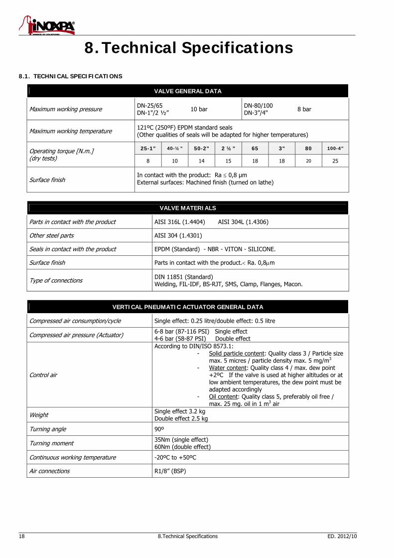
8. Technical Specifications 8.1. TECHNICAL SPECIFICATIONS
VALVE GENERAL DATA
Maximum working pressure
DN-25/65 DN-1"/2 ½” 10 bar DN-80/100
DN-3”/4" 8 bar
Maximum working temperature
121ºC (250ºF) EPDM standard seals (Other qualities of seals will be adapted for higher temperatures)
Operating torque [N.m.] (dry tests)
25-1” 40-½” 50-2” 2 ½” 65 3” 80 100-4”
8 10 14 15 18 18 20 25
Surface finish In contact with the product: Ra 0,8 μm External surfaces: Machined finish (turned on lathe)
VALVE MATERIALS
Parts in contact with the product AISI 316L (1.4404) AISI 304L (1.4306)
Other steel parts AISI 304 (1.4301)
Seals in contact with the product EPDM (Standard) - NBR - VITON - SILICONE.
Surface finish Parts in contact with the product. Ra. 0,8m
Type of connections
DIN 11851 (Standard) Welding, FIL-IDF, BS-RJT, SMS, Clamp, Flanges, Macon.
VERTICAL PNEUMATIC ACTUATOR GENERAL DATA
Compressed air consumption/cycle Single effect: 0.25 litre/double effect: 0.5 litre
Compressed air pressure (Actuator) 6-8 bar (87-116 PSI) Single effect 4-6 bar (58-87 PSI) Double effect
Control air
According to DIN/ISO 8573.1: - Solid particle content: Quality class 3 / Particle size
max. 5 micres / particle density max. 5 mg/m3 - Water content: Quality class 4 / max. dew point
+2ºC If the valve is used at higher altitudes or at low ambient temperatures, the dew point must be adapted accordingly
- Oil content: Quality class 5, preferably oil free / max. 25 mg. oil in 1 m3 air
Weight Single effect 3.2 kg Double effect 2.5 kg
Turning angle 90º
Turning moment 35Nm (single effect) 60Nm (double effect)
Continuous working temperature -20ºC to +50ºC
Air connections R1/8” (BSP)
ED. 2012/10 8.Technical Specifications 19
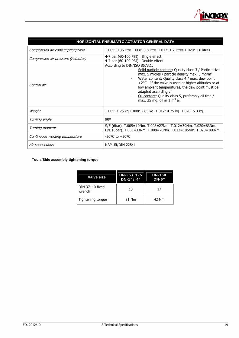
HORIZONTAL PNEUMATIC ACTUATOR GENERAL DATA
Compressed air consumption/cycle T.005: 0.36 litre T.008: 0.8 litre T.012: 1.2 litres T.020: 1.8 litres.
Compressed air pressure (Actuator) 4-7 bar (60-100 PSI) Single effect 4-7 bar (60-100 PSI) Double effect
Control air
According to DIN/ISO 8573.1: - Solid particle content: Quality class 3 / Particle size
max. 5 micres / particle density max. 5 mg/m3 - Water content: Quality class 4 / max. dew point
+2ºC If the valve is used at higher altitudes or at low ambient temperatures, the dew point must be adapted accordingly
- Oil content: Quality class 5, preferably oil free / max. 25 mg. oil in 1 m3 air
Weight T.005: 1.75 kg T.008: 2.85 kg T.012: 4.25 kg T.020: 5.3 kg.
Turning angle 90º
Turning moment S/E (6bar). T.005=10Nm. T.008=27Nm. T.012=39Nm. T.020=63Nm. D/E (6bar). T.005=33Nm. T.008=70Nm. T.012=105Nm. T.020=160Nm.
Continuous working temperature -20ºC to +50ºC
Air connections NAMUR/DIN 228/1
Tools/Side assembly tightening torque
Valve size DN-25 / 125 DN-1” / 4”
DN-150 DN-6”
DIN 37110 fixed wrench 13 17
Tightening torque 21 Nm 42 Nm
20 8.Technical Specifications ED. 2012/10
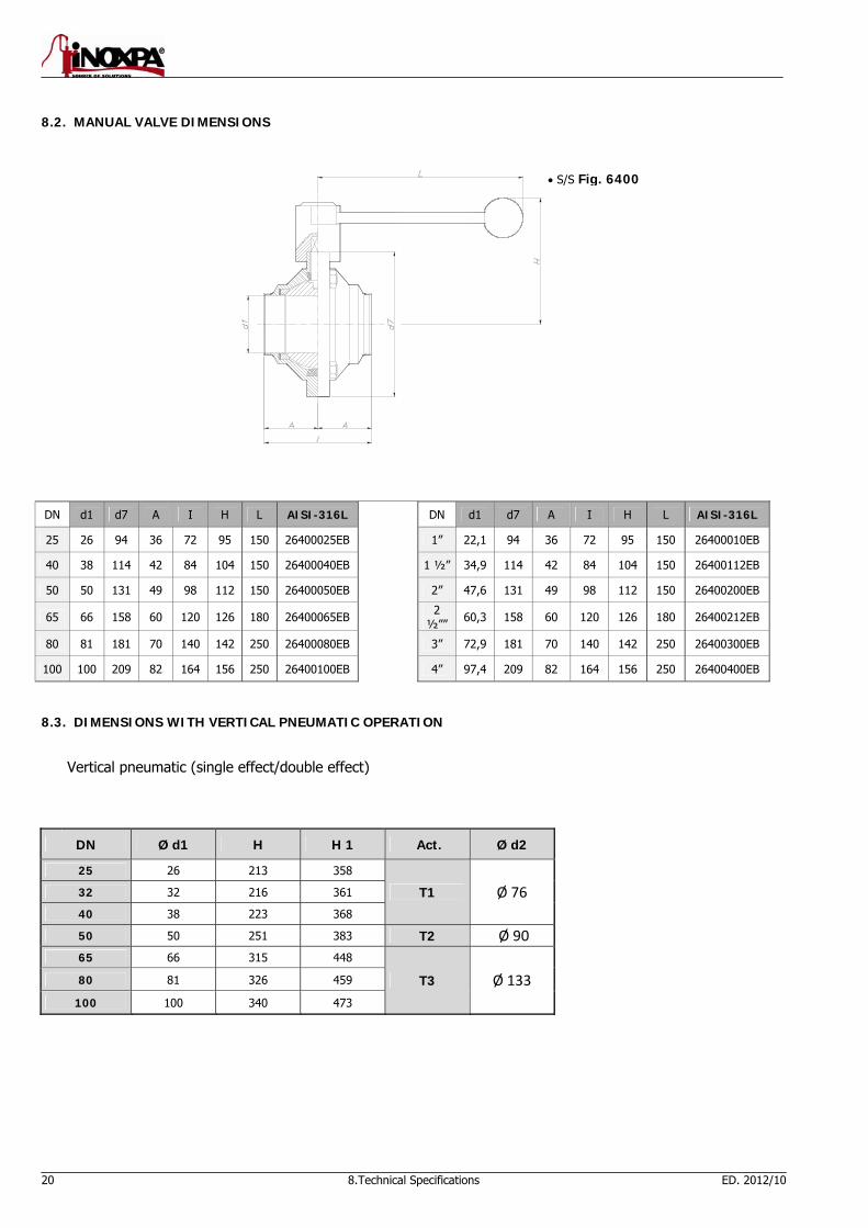
8.2. MANUAL VALVE DIMENSIONS
DN d1 d7 A I H L AISI-316L DN d1 d7 A I H L AISI-316L
25 26 94 36 72 95 150 26400025EB 1” 22,1 94 36 72 95 150 26400010EB
40 38 114 42 84 104 150 26400040EB 1 ½” 34,9 114 42 84 104 150 26400112EB
50 50 131 49 98 112 150 26400050EB 2” 47,6 131 49 98 112 150 26400200EB
65 66 158 60 120 126 180 26400065EB 2 ½”” 60,3 158 60 120 126 180 26400212EB
80 81 181 70 140 142 250 26400080EB 3” 72,9 181 70 140 142 250 26400300EB
100 100 209 82 164 156 250 26400100EB 4” 97,4 209 82 164 156 250 26400400EB
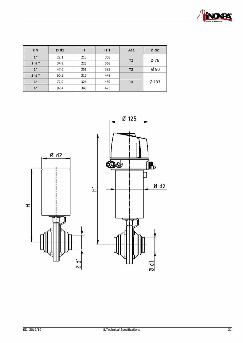
8.3. DIMENSIONS WITH VERTICAL PNEUMATIC OPERATION
Vertical pneumatic (single effect/double effect)
DN Ø d1 H H 1 Act. Ø d2
25 26 213 358
T1 Ø 76 32 32 216 361
40 38 223 368
50 50 251 383 T2 Ø 90
65 66 315 448
T3 Ø 133 80 81 326 459
100 100 340 473
S/S Fig. 6400
ED. 2012/10 8.Technical Specifications 21
DN Ø d1 H H 1 Act. Ø d2
1” 22,1 213 358 T1 Ø 76
1 ½” 34,9 223 368
2” 47,6 251 383 T2 Ø 90
2 ½” 60,3 315 448
T3 Ø 133 3” 72,9 326 459
4” 97,4 340 473
22 8.Technical Specifications ED. 2012/10
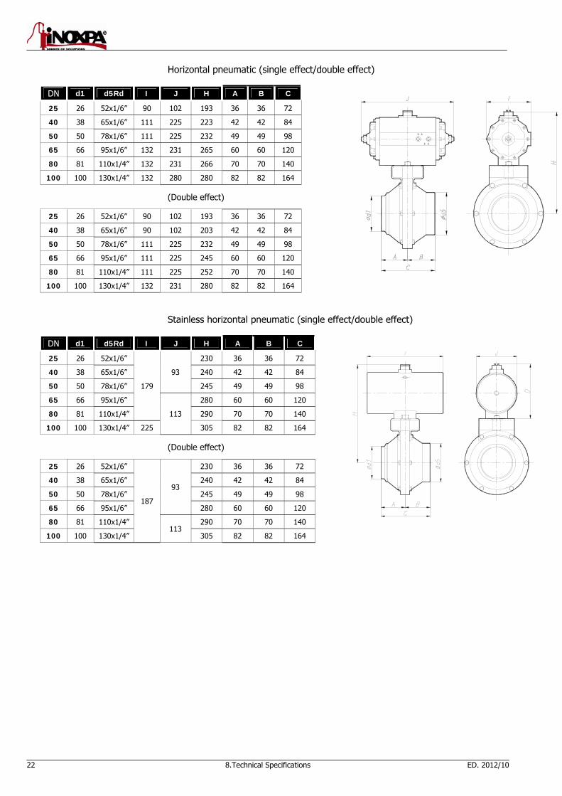
Horizontal pneumatic (single effect/double effect)
DN d1 d5Rd I J H A B C
25 26 52x1/6” 90 102 193 36 36 72
40 38 65x1/6” 111 225 223 42 42 84
50 50 78x1/6” 111 225 232 49 49 98
65 66 95x1/6” 132 231 265 60 60 120
80 81 110x1/4” 132 231 266 70 70 140
100 100 130x1/4” 132 280 280 82 82 164
(Double effect)
25 26 52x1/6” 90 102 193 36 36 72
40 38 65x1/6” 90 102 203 42 42 84
50 50 78x1/6” 111 225 232 49 49 98
65 66 95x1/6” 111 225 245 60 60 120
80 81 110x1/4” 111 225 252 70 70 140
100 100 130x1/4” 132 231 280 82 82 164
Stainless horizontal pneumatic (single effect/double effect)
DN d1 d5Rd I J H A B C
25 26 52x1/6”
179
93
230 36 36 72
40 38 65x1/6” 240 42 42 84
50 50 78x1/6” 245 49 49 98
65 66 95x1/6”
113
280 60 60 120
80 81 110x1/4” 290 70 70 140
100 100 130x1/4” 225 305 82 82 164
(Double effect)
25 26 52x1/6”
187
93
230 36 36 72
40 38 65x1/6” 240 42 42 84
50 50 78x1/6” 245 49 49 98
65 66 95x1/6” 280 60 60 120
80 81 110x1/4” 113
290 70 70 140
100 100 130x1/4” 305 82 82 164
8.Technical Specifications 23
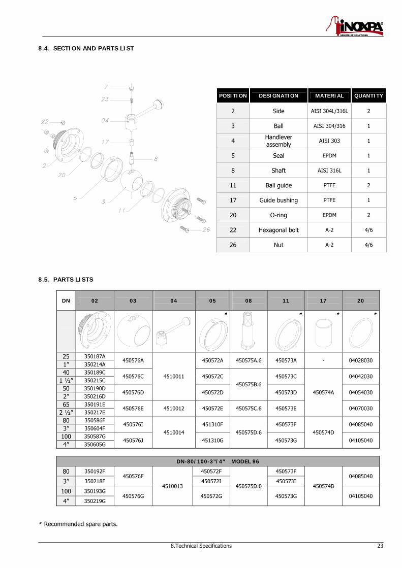
8.4. SECTION AND PARTS LIST
POSITION DESIGNATION MATERIAL QUANTITY
2 Side AISI 304L/316L 2
3 Ball AISI 304/316 1
4 Handlever assembly
AISI 303 1
5 Seal EPDM 1
8 Shaft AISI 316L 1
11 Ball guide PTFE 2
17 Guide bushing PTFE 1
20 O-ring EPDM 2
22 Hexagonal bolt A-2 4/6
26 Nut A-2 4/6
8.5. PARTS LISTS
DN
02
03
04
05
08
11
17
20
* *
*
*
25 350187A 450576A
4510011
450572A 450575A.6 450573A - 04028030 1” 350214A 40 350189C
450576C 450572C 450575B.6
450573C
450574A
04042030 1 ½” 350215C 50 350190D
450576D 450572D 450573D 04054030 2” 350216D 65 350191E
450576E 4510012 450572E 450575C.6 450573E 04070030 2 ½” 350217E 80 350586F
450576I 4510014
451310F 450575D.6
450573F 450574D
04085040 3” 350604F
100 350587G 450576J 451310G 450573G 04105040
4” 350605G
DN-80/100-3”/4” MODEL 96
80 350192F 450576F
4510013
450572F
450575D.0
450573F
450574B
04085040 3” 350218F 450572I 450573I
100 350193G 450576G 450572G 450573G 04105040
4” 350219G
* Recommended spare parts.
NOTES

NOTES

INOXPA, S.A. DELEGACIÓN NORD-ESTE / Óc/ Telers, 54 – PO Box 174 BARBERÀ DEL VALLÈS (BCN) ZARAGOZA
17820 BANYOLES (GIRONA) Tel: 937 297 280 Tel: 976 591 942Tel: 34 972575200 Fax: 937 296 220 Fax: 976 591 473Fax: 34 972575502 e-mail: [email protected] e-mail: [email protected] e-mail: [email protected] www.inoxpa.com DELEGACIÓN LEVANTE DELEGACIÓN CENTRO DELEGACIÓN STA PATERNA (VALENCIA) ARGANDA DEL REY (MADRID) GALDACANO (BILBAO) Tel: 963 170 101 Tel: 918 716 084 Tel: 944 572 058Fax: 963 777 539 Fax: 918 703 641 Fax: 944 571 806e-mail: [email protected] e-mail: [email protected] e-mail: [email protected] DELEGACIÓN SUR LA CISTÉRNIGA (VALLADOLID) LOGROÑO JEREZ DE LA FRONTERA (CÁDIZ) Tel: 983 403 197 Tel: 941 228 622 Tel / Fax: 956 140 193 Fax: 983 402 640 Fax: 941 204 290 e-mail: [email protected] e-mail: [email protected] e-mail: [email protected] INOXPA SOLUTIONS LEVANTE INOXPA SOLUTIONS FRANCE PATERNA (VALENCIA) GLEIZE CHAMBLY (PARIS)Tel: 963 170 101 Tel: 33 474627100 Tel: 33 130289100 Fax: 963 777 539 Fax: 33 474627101 Fax: 33 130289101 e-mail: [email protected] e-mail: [email protected] e-mail: [email protected]
INOXPA AUSTRALIA PTY (LTD) ST. SEBASTIEN sur LOIRE WAMBRECHIES MORNINGTON (VICTORIA) Tel/Fax: 33 130289100 Tel: 33 320631000 Tel: 61 3 5976 8881 e-mail: [email protected] Fax: 33 320631001 Fax: 61 3 5976 8882 e-mail: [email protected] e-mail: [email protected]
INOXPA ALGERIE INOXPA SOUTH AFRICA (PTY) LTD INOXPA USA, Inc
ROUIBA JOHANNESBURG SANTA ROSA
Tel: 213 21856363 / 21851780 Tel: 27 117 945 223 Tel: 1 7075 853 900
Fax: 213 21854431 Fax: 27 866 807 756 Fax: 1 7075 853 908
e-mail: [email protected] e-mail: [email protected] e-mail: [email protected] INOXPA UK LTD S.T.A. PORTUGUESA LDA INOXPA ITALIA, S.R.L. SURREY VALE DE CAMBRA BALLO DI MIRANO – VENEZIA Tel: 44 1737 378 060 / 079 Tel: 351 256 472 722 Tel: 39 041 411 236 Fax: 44 1737 766 539 Fax: 351 256 425 697 Fax: 39 041 5128 414 e-mail: [email protected] e-mail: [email protected] e-mail: [email protected] INOXPA SKANDINAVIEN A/S IMPROVED SOLUTIONS INOXPA INDIA PVT. LTD. HORSENS (DENMARK) VALE DE CAMBRA Maharashtra, INDIA. Tel: 45 76 286 900 Tel: 351 256 472 140 / 138 Tel: 91 2065 008 458 Fax: 45 76 286 909 Fax: 351 256 472 130 [email protected] e-mail: [email protected] e-mail: [email protected]
INOXPA SPECIAL PROCESSING INOXRUS
EQUIPMENT, CO., LTD. MOSCOW (RUSIA) SAINT PETERSBURG (RUSIA) JIAXING (China) Tel / Fax: 74 956 606 020 Тel: 78 126 221 626 / 927 Tel.: 86 573 83 570 035 / 036 e-mail: [email protected] Fax: 78 126 221 926 Fax: 86 573 83 570 038 e-mail: [email protected] INOXPA WINE SOLUTIONS INOXPA UCRANIA VENDARGUES (FRANCE) KIEV Tel: 33 971 515 447 Tel: 38 050 720 8692 Fax: 33 467 568 745 e-mail: [email protected]: [email protected] / [email protected]
In addition to our branch offices, INOXPA operates with an independent distributor network which encompasses a total of more than 50 countries throughout the world. For more information consult our web page: www.inoxpa.com Orientative information. We reserve the right to modify any material or characteristic without prior notice.


