Installation Plan Washing Machine - Miele USA | … 10 441 630/ 02 Legend: Connection required...
12
Installation Plan Washing Machine PW 6068 LP Read all operation and installation instructions prior to assembly, installation, and initial operation to prevent injury and machine damage. en - US 10 441 630/ 02
Transcript of Installation Plan Washing Machine - Miele USA | … 10 441 630/ 02 Legend: Connection required...

Installation Plan
Washing Machine
PW 6068 LP Read all operation and installation instructions prior to
assembly, installation, and initial operation
to prevent injury and machine damage.
en - US
10 441 630/ 02

2 10 441 630/ 02
Legend:
Connection required
Connection optional or required for
a specific model
AV Drain valve KW Cold water connection
AW Waste water connection LP Soap water pump
B Appliance fastening PA Equipotential bonding
BW Service water connection SLA Peak load connection
DOS Dosing unit connection UG Base, closed
EL Electrical connection UO Base, open
F Adjustable appliance mounts WTV Washer/dryer connection
KG Payment device WW Hot water connection
KGA Payment device connection XKM Communication module
Alteration rights reserved 08/14/155
PW 6068 en - US
10 441 630 / 02 3
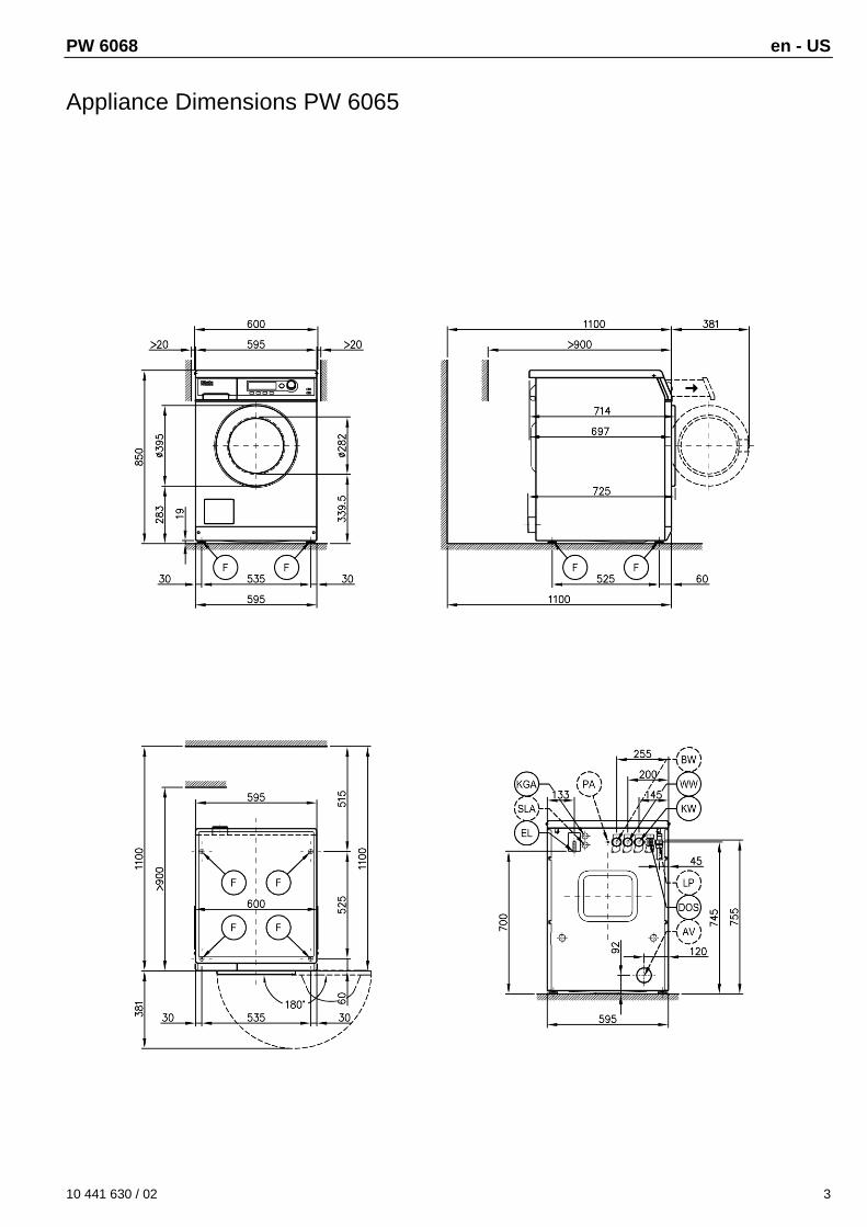
Appliance Dimensions PW 6065
en - US PW 6068
4 10 441 630/ 02
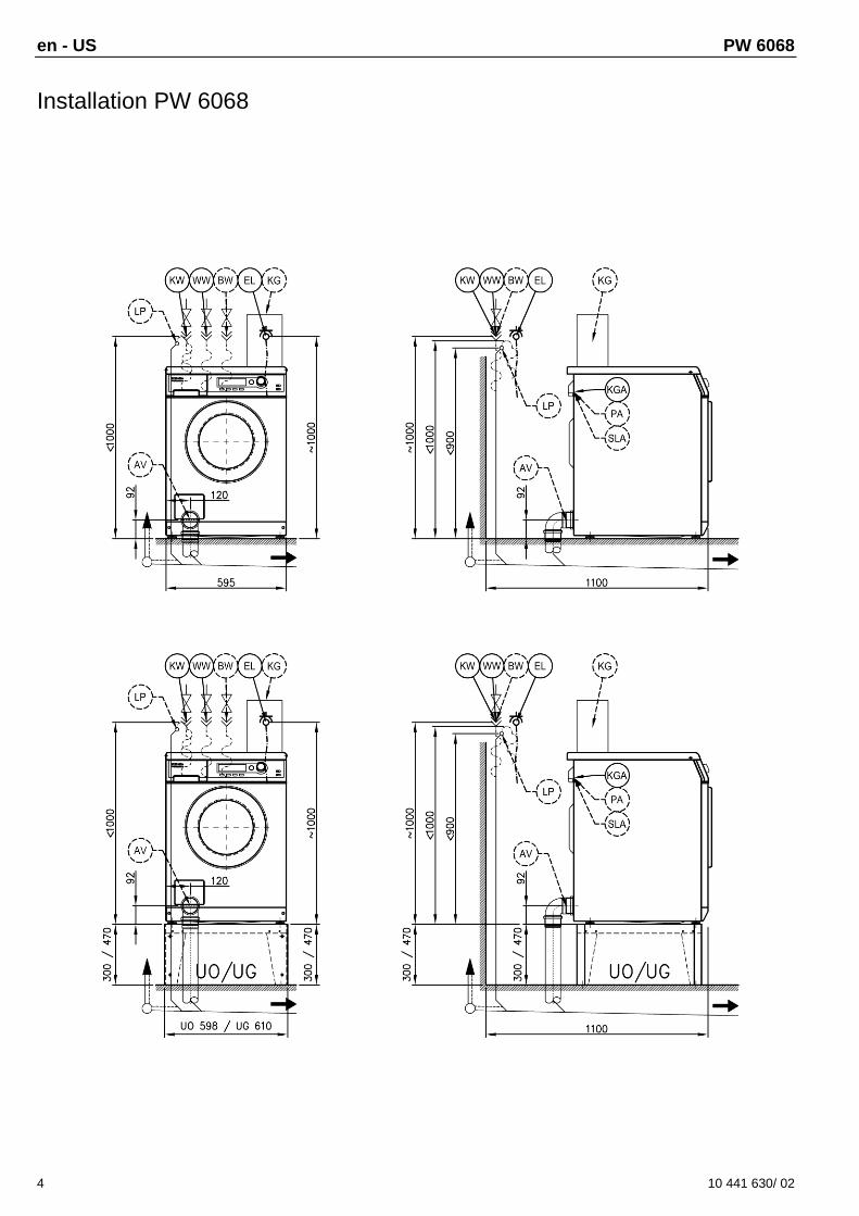
Installation PW 6068

PW 6068 en - US
10 441 630 / 02 5
Washer/Dryer Stack PW 6068

en - US PW 6068
6 10 441 630/ 02
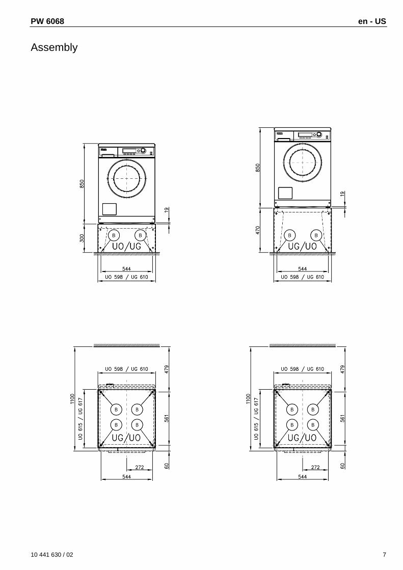
Assembly
PW 6068 en - US
10 441 630 / 02 7
Assembly

en - US PW 6068
= standard, = optional, + = only upon enquiry, - not available
8 10 441 630/ 02
Technical Data PW 6068 LP
Drum volume 59 l
Filling weight 14.3 lbs (6.5 kg)
Loading door, diameter 11 1/8“ (282 mm)
Max. spin speed 1400 RPM
g-factor 526
Residual moisture (standard load) 49%
Electrical connection (EL)
Standard voltage (US only) 2 AC 208-240 V
Frequency 60 Hz
Total connections 4.0 kW - 5,2 kW
Fuse protection 2 x 30 A
Connection cable, minimum cross-section 10/3 AWG
Connection cable with plug
Connection cable, length 6‘ 6 ¾“ (2000 mm)
Standard voltage (CDN only) 2 AC 208 V 2 AC 240 V
Frequency 60 Hz 60 Hz
Total connections 4.0 kW 5,2 kW
Fuse protection 2 x 20 A 2 x 30 A
Connection cable, minimum cross-section 10/3 AWG 10/3 AWG
Connection cable with plug
Connection cable, length 6‘ 6 ¾“ (2000 mm) 6‘ 6 ¾“ (2000 mm)
Cold water (KW)
Permissible water flow pressure 100 – 1000 kPa
Required volume flow (cold water connection only) 11 l/min
Required volume flow (for additional hot water connection) 10 l/min
Average water consumption (60°C standard program) 40 l/h
User-supplied connection with external thread as per DIN 44991 (flat sealing) ¾“
Connection hose ½“ with screw fitting ¾“
Connecting hose, length 5‘ 1“ (1550 mm)
Hot water (WW)
Max. inlet temperature 158°F (70°C)
Permissible water flow pressure 100 – 1000 kPa
Required volume flow 11 l/min
Average water consumption (60°C standard program) 13 l/h
User-supplied connection with external thread (flat sealing) ¾“
Connection hose ½“ with screw fitting ¾“
Connecting hose, length 5‘ 1“ (1550 mm)
Service water (BW)
Kit with additional inlet valve
Permissible water flow pressure 100 – 1000 kPa
Required volume flow 11 l/min
Average water consumption (60°C standard program) 17 l/h
User-supplied connection with external thread as per DIN 44991 (flat sealing) ¾“
Connection hose ½“ with screw fitting ¾“
Connecting hose, length 5‘ 1“ (1550 mm)
Drain valve (AV)
Connecting piece (external diameter) -
Max. waste water temperature
Max. short-time flow volume -
Soap pump (LP)
Hose connector (external diameter) 7/8“ (22 mm) (DN22)
Max. waste water temperature 194°F (90°C)
PW 6068 en - US
= standard, = optional, + = only upon enquiry, - not available
10 441 630/ 0 9
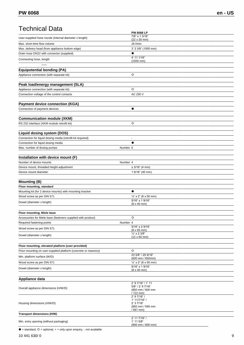
Technical Data PW 6068 LP
User-supplied hose nozzle (internal diameter x length) 7/8“ x 1 3/16“ (22 x 30 mm)
Max. short-time flow volume 26 l/min
Max. delivery head (from appliance bottom edge) 3‘ 3 3/8“ (1000 mm)
Drain hose DN22 with connector (supplied)
Connecting hose, length 4‘ 11 1/16“ (1500 mm)
Equipotential bonding (PA)
Appliance connection (with separate kit)
Peak load/energy management (SLA)
Appliance connection (with separate kit)
Connection voltage of the control contacts AC 230 V
Payment device connection (KGA)
Connection of payment devices
Communication module (XKM)
RS 232 interface (XKM module retrofit kit)
Liquid dosing system (DOS)
Connection for liquid dosing media (retrofit kit required) -
Connection for liquid dosing media
Max. number of dosing pumps Number 6
Installation with device mount (F)
Number of device mounts Number 4
Device mount, threaded height-adjustment ± 3/16“ (4 mm)
Device mount diameter 1 9/16“ (40 mm)
Mounting (B)
Floor mounting, standard
Mounting kit (for 2 device mounts) with mounting bracket
Wood screw as per DIN 571 ¼“ x 2“ (6 x 50 mm)
Dowel (diameter x length) 5/16“ x 1 9/16“ (8 x 40 mm)
Floor mounting, Miele base
Accessories for Miele base (fasteners supplied with product)
Required fastening points Number 4
Wood screw as per DIN 571 5/16“ x 2 9/16“ (8 x 65 mm)
Dowel (diameter x length) ½“ x 2 3/8“ (12 x 60 mm)
Floor mounting, elevated platform (user-provided)
Floor mounting on user-supplied platform (concrete or masonry)
Min. platform surface (W/D) 23 5/8“ / 25 9/16“ (600 mm / 650mm)
Wood screw as per DIN 571 ¼“ x 2“ (6 x 50 mm)
Dowel (diameter x length) 5/16“ x 1 9/16“ (8 x 40 mm)
Appliance data
Overall appliance dimensions (H/W/D)
2‘ 9 7/16“ / 1‘ 11 5/8“ / 2‘ 9 7/16“ (850 mm / 600 mm / 722 mm)
Housing dimensions (H/W/D)
2‘ 9 7/16“ / 1‘ 11/7/16“ / 2‘ 3 7/16“ (850 mm / 595 mm / 697 mm)
Transport dimensions (H/W)
Min. entry opening (without packaging) 2‘ 11 7/16“ / 1‘ 11 5/8“ (900 mm / 600 mm)

en - US PW 6068
= standard, = optional, + = only upon enquiry, - not available
10 10 441 630/ 02
Technical Data PW 6068 LP
Installation dimensions
Min. clearance appliance to side 13/16“ (20 mm)
Recommended clearance appliance to side, washer/dryer stack >11 ¾“ (300 mm)
Min. wall clearance from appliance front 2‘ 11 7/16“ (900 mm)
Recommended min. wall clearance from appliance front 3‘ 7 5/16“ (1100 mm)
Weights and loads
Appliance weight (net weight) 234 lbs (106 kg)
Max. floor load during operation 2820 N
Max. static floor load 1455 N
Max. dynamic floor load 1365 N
Drum max. rotary frequency 22 Hz
Appliance emissions
Emission sound pressure level at a workplace <70 dB(A)
Heat emission into the installation space 250 W
Options / Accessories Features
Base, closed (UG)
Base closed, H 11 13/16“ (300 mm) (UG 5005) Base galvanized, stainless steel side panels
Base closed, H 1‘ 6 ½“ (470 mm) (UG 5005-47) Base galvanized, "octoblue" heat cure coated side panels
Base closed, H 2‘ 5 ½“ (750 mm) (UG 5005-75) Base galvanized, "octoblue" heat cure coated side panels
Base, open (UO)
Base open, H 11 13/16“ (300 mm) (UO 5005) Base galvanized, "octoblue" heat cure coated surface
Base open, H 1‘ 6 ½“ (470 mm) (UO 5005) Base galvanized, "octoblue" heat cure coated surface
Washer/dryer connection (WTV)
Stainless steel kit (WTV 5062) Kit for the connection of washer and dryer
"Lotus white" kit (WTV 5061) Kit for the connection of washer and dryer
Payment devices (KG)
Single-unit operation (C 4060) Payment device for tokens, program operation only
Single-unit operation (C 4065) Payment device with coins, time and program operation
Single-unit operation (C 4070) Payment device for coins and tokens, time and program operation
Multi-unit operation (C 5200 BT) Basic unit, debit card payment device (for max. 8 terminals)
Remote bundle (ABT 5220) Terminal monitoring with Bluetooth communication (required for each terminal)
Accessories
Peak load/energy management connection (BSS) Connection for peak load and energy management functions
Equipotential bonding kit The assembly kit can be ordered from Customer Service.
XKM communication module (XKM RS 232-10) Retrofit kit XKM module with RS 232 incl. installation kit
PW 6068 en - US
10 441 630/ 02 11
Installation and planning notes
Installation prerequisites
The appliance must be connected only to a system designed in accordance with national legislation, regulations and directives, as well as local codes and standards.
In addition, all regulations by utilities, accident prevention regulations, insurance guidelines and recognized codes of practice valid at the installation site must be adhered to.
Transport and placement
The washing machine must not be transported without transport safety. Do not discard the transport safety, because you will have to reinstall it prior to transporting the washing machine (during a move, for example).
General conditions of operation
Ambient temperature of the installation space: +35°F (2°C) to +95° (35°C).
Depending on the properties of the installation site, noise and/or vibrations may be transmitted into the building. It is recommended to have a noise protection expert examine the appliance's installation site when more stringent demands on sound insulation are made.
Electrical connection
Depending on the design, the appliance may be fitted with a connection cable with or without a plug.
The appliance must be connected only to an electric supply designed in accordance with national and local regulations. The installation must be performed by a qualified electrician.
The appliance data plate indicates the nominal power consumption and the appropriate fuse capacity. Compare the specifications on the data plate with those of the electrical power supply.
The appliance can be connected either via a permanent connection or a plug-in connection. However, we recommend connecting the appliance via a plug connection so that an electrical safety check can be carried out, e.g. during repair or maintenance.
If a permanent connection is intended, an all-pole disconnection device must be provided at the installation side. Disconnect devices may be switches with a contact gap of more than 3 mm, such as MCBs, fuses and guards.
The plug-in connection or disconnect device must be accessible at all times. You must be able to lock the separator or monitor it at all times in case the appliance has to be disconnected from the power supply.
Only a certified or approved electrician may perform the initial installation of the connection, change the system or inspect the ground conductor, including a determination of the correct protection, because they are familiar with the relevant regulations and the particular requirements by the electrical utility.
Comply with the switch-over instructions on the wiring diagram when switching the appliance to a different voltage. Only authorized distributors or Miele customer service representatives may convert the appliance. In this event, it is also necessary to
adjust the heat output.
Devices for an automatic shut-down of the appliance (such as timers) must not be installed.
The conductor cross-section information in the technical data refers only to the required connecting cable. Refer to the applicable national and local regulations for calculating the other dimensions.
Cold water connection
You may connect the washing machine to a drinking water system without a backflow preventer because it has been designed according to the applicable standards for drinking water protection.
For the connection, you require a water shut-off valve or a tap with connecting thread. If such is missing, only an authorized plumber may connect the appliance to the drinking water pipe.
A suitable connection hose with screw fitting is supplied with the appliance.
Authorized Miele distributors and Miele Customer Service representatives can provide you with hoses of 8‘ 2 ½“ or 13‘ 1 ½“ (2.5 or 4 m) length to extend the hose.
Hot water connection
The connection conditions for the hot water connection to up to 158°F (70°C) are the same as those for the cold water connection.
A suitable connection hose with screw fitting is supplied with the appliance.
The appliance may be connected to a hot water system from 158° (70°C) to 185° (85°C) max., however, you will require a special heat-resistant inlet hose.
Purchase this inlet hose from a Miele authorized distributor or Miele Customer Service. In addition, the appliance must be programmed correspondingly by Miele Technical Service or an authorized dealer.
For functional reasons, it is not possible to connect the appliance to a hot water supply only.
If the building does not have a hot water supply, the hot water connection must be connected to an existing cold water supply.
Alternatively, close the hot water connection with the supplied dummy cap and convert the appliance controller to colt water inlet.
In this event, you must add the water demand for hot water to the cold water demand.
Service water connection
The service water connection can be optionally retrofitted using an additional kit.
The same connection conditions as for the cold water connection apply.
Soap water pump
The appliance drains through a pump with a 1 m delivery head. For the water to drain freely, the hose must be free of kinks. The elbow at the hose end can be rotated and removed, if necessary.
Water drain options:
1. Direct connection to a plastic pipe with rubber sleeve (syphon not mandatory).
2. Attach to a sink with a plastic fitting
3. Drain into a floor drain (gully).
en - US PW 6068
12 10 441 630/ 02
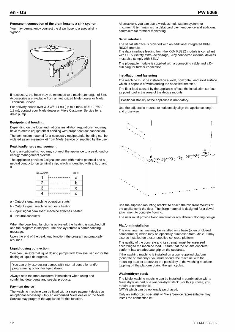
Permanent connection of the drain hose to a sink syphon
You may permanently connect the drain hose to a special sink syphon.
If necessary, the hose may be extended to a maximum length of 5 m. Accessories are available from an authorized Miele dealer or Miele Technical Service.
For delivery heads over 3‘ 3 3/8“ (1 m) (up to a max. of 5‘ 10 7/8“ / 1.8 m), contact your Miele dealer or Miele Customer Service for a drain pump.
Equipotential bonding
Depending on the local and national installation regulations, you may have to create equipotential bonding with proper contact connection.
The connection material for a necessary equipotential bonding can be ordered as an assembly kit from Miele Service or supplied by the user.
Peak load/energy management
Using an optional kit, you may connect the appliance to a peak load or energy management system.
The appliance provides 3 signal contacts with mains potential and a neutral conductor on terminal strip, which is identified with a, b, c, and d.
a - Output signal: machine operation starts
b - Output signal: machine requests heating
c - Input signal peak load: machine switches heater
d – Neutral conductor
When the peak load function is activated, the heating is switched off and the program is stopped. The display returns a corresponding message.
Upon the end of the peak load function, the program automatically resumes.
Liquid dosing connection
You can use external liquid dosing pumps with low-level sensor for the dosing of liquid detergents.
You can only use dosing pumps with internal controller and/or programming option for liquid dosing.
Always note the manufacturers' instructions when using and combining detergents and special products.
Payment device
The washing machine can be fitted with a single payment device as an optional accessory. Only an authorized Miele dealer or the Miele Service may program the appliance for this function.
Alternatively, you can use a wireless multi-station system for maximum 8 terminals with a debit card payment device and additional controllers for terminal monitoring.
Serial interface
The serial interface is provided with an additional integrated XKM RS323 module. The data interface leading from the XKM RS232 module is compliant with SELV (safety extra-low voltage). Any connected external devices must also comply with SELV.
The pluggable module is supplied with a connecting cable and a D-sub plug for further connection.
Installation and fastening
The machine must be installed on a level, horizontal, and solid surface which is capable of withstanding the specified stresses.
The floor load caused by the appliance affects the installation surface as point load in the area of the device mounts.
Positional stability of the appliance is mandatory.
Use the adjustable mounts to horizontally align the appliance length- and crosswise.
Use the supplied mounting bracket to attach the two front mounts of the appliance to the floor. The fixing material is designed for a dowel attachment to concrete flooring.
The user must provide fixing material for any different flooring design.
Platform installation
The washing machine may be installed on a base (open or closed compartment) which may be optionally purchased from Miele. It may also be installed on a user-supplied concrete platform.
The quality of the concrete and its strength must be assessed according to the machine load. Ensure that the on-site concrete platform has an adequate grip on the substrate.
If the washing machine is installed on a user-supplied platform (concrete or masonry), you must secure the machine with the mounting bracket to prevent the possibility of the washing machine toppling off the platform during the spin cycles.
Washer/dryer stack
The Miele washing machine can be installed in combination with a Miele dryer as part of a washer-dryer stack. For this purpose, you require a connection kit (WTV) which can be optionally purchased.
Only an authorized specialist or Miele Service representative may install the connection kit.