Installation & Operator’s Guide - WEP Strantrol Set...Installation & Operator’s Guide...
40
Installation & Operator’s Guide Strantrol® Set Point NX Controller ST.SetPointNX.UA.IM.0207 Water Technologies
Transcript of Installation & Operator’s Guide - WEP Strantrol Set...Installation & Operator’s Guide...

Installation & Operator’s Guide
Strantrol® Set Point NX Controller ST.SetPointNX.UA.IM.0207
Water Technologies

WARNING NOTIFICATIONS
Warning Notifications.....................................................................................................i
Mounting – Chapter 1....................................................................................................1 1.1 Environmental Conditions..............................................................................................1
Plumbing – Chapter 2 ....................................................................................................3 2.1 Sample Stream General Recommendations and Precautions ..........................................3 2.2 Assembling the Flowcell (Drawing Appendix A) ............................................................3 2.3 Installing the Flowcell (Drawing Appendix B) ................................................................4 2.4 Checking the Flowcell ..................................................................................................5
Hardware – Chapter 3....................................................................................................7 3.1 Power Board Layout .....................................................................................................7 3.2 Display Board Layout....................................................................................................8
Electrical – Chapter 4.....................................................................................................9 4.1 Connecting Power to the Set Point NX (Drawing Appendix C)........................................9 4.2 Optional: Interlocking Power to Set Point NX Feed Relays (Drawing Appendix C) .........11 4.3 Connecting Feed Devices to the Set Point NX Relays (Drawing Appendix D).................11 4.4 Connecting Sensors to the Set Point NX......................................................................13 4.5 Connecting Flow Switches to the Set Point NX............................................................14
Programming – Chapter 5............................................................................................15 5.1 Control Inhibit............................................................................................................15 5.2 Set Point NX Menu Structure ......................................................................................15 5.3 Set Point NX Button Functions....................................................................................15 5.4 Changing the Overfeed Lock Time (Failsafe) ...............................................................15 5.5 Resetting the Overfeed Lock Time (Failsafe)................................................................15 5.6 Enabling the Sensor Wash (Relay #3)..........................................................................15 5.7 Changing the pH Feed Direction .................................................................................16 5.8 Auxiliary Relay (Relay #3) ...........................................................................................16 5.9 Changing Feed Modes (ON/OFF or Time Based Proportional).......................................16 5.10 Changing TBP Span ....................................................................................................16 5.11 Changing TBP Time Base ............................................................................................16 5.12 Changing Cl/Br Lockout span ......................................................................................17 5.13 Changing the Sensor Calibration.................................................................................17 5.14 Viewing the Set Points................................................................................................17 5.15 Viewing the Alarm set points......................................................................................17 5.16 Changing the Set Points .............................................................................................17 5.17 Changing the Alarm Points .........................................................................................17 5.18 Changing the Temperature Units................................................................................18 5.19 Alarm Messages .........................................................................................................18
Maintenance – Chapter 6 ............................................................................................19 6.1 Cleaning the Sensors..................................................................................................19 6.2 Cleaning the Set Point NX...........................................................................................19 6.3 Parts and Supplies ......................................................................................................19
Appendix A..................................................................................................................21 Appendix B ..................................................................................................................23 Appendix C ..................................................................................................................25 Appendix D..................................................................................................................27

WARNING NOTIFICATIONS
i
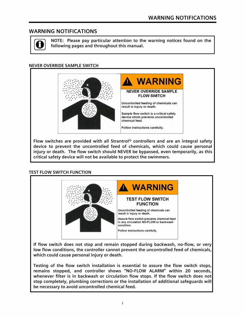
If flow switch does not stop and remain stopped during backwash, no-flow, or very low flow conditions, the controller cannot prevent the uncontrolled feed of chemicals, which could cause personal injury or death. Testing of the flow switch installation is essential to assure the flow switch stops, remains stopped, and controller shows “NO-FLOW ALARM” within 20 seconds, whenever filter is in backwash or circulation flow stops. If the flow switch does not stop completely, plumbing corrections or the installation of additional safeguards will be necessary to avoid uncontrolled chemical feed.
WARNING NOTIFICATIONS NEVER OVERRIDE SAMPLE SWITCH TEST FLOW SWITCH FUNCTION
Flow switches are provided with all Strantrol® controllers and are an integral safety device to prevent the uncontrolled feed of chemicals, which could cause personal injury or death. The flow switch should NEVER be bypassed, even temporarily, as this critical safety device will not be available to protect the swimmers.
NOTE: Please pay particular attention to the warning notices found on the following pages and throughout this manual.
WARNING NOTIFICATIONS
ii
NEVER CONNECT FEEDER DIRECTLY TO POWER SOURCE ALWAYS USE ANTI-SIPHON DEVICES
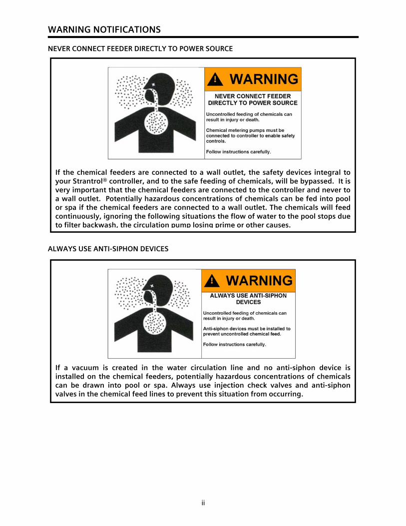
If the chemical feeders are connected to a wall outlet, the safety devices integral to your Strantrol® controller, and to the safe feeding of chemicals, will be bypassed. It is very important that the chemical feeders are connected to the controller and never to a wall outlet. Potentially hazardous concentrations of chemicals can be fed into pool or spa if the chemical feeders are connected to a wall outlet. The chemicals will feed continuously, ignoring the following situations the flow of water to the pool stops due to filter backwash, the circulation pump losing prime or other causes.
If a vacuum is created in the water circulation line and no anti-siphon device is installed on the chemical feeders, potentially hazardous concentrations of chemicals can be drawn into pool or spa. Always use injection check valves and anti-siphon valves in the chemical feed lines to prevent this situation from occurring.
WARNING NOTIFICATIONS
iii
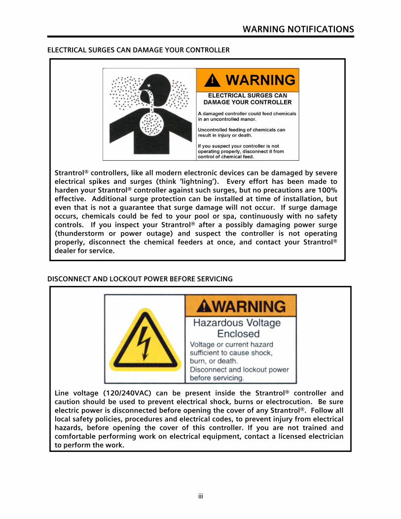
Strantrol® controllers, like all modern electronic devices can be damaged by severe electrical spikes and surges (think ‘lightning’). Every effort has been made to harden your Strantrol® controller against such surges, but no precautions are 100% effective. Additional surge protection can be installed at time of installation, but even that is not a guarantee that surge damage will not occur. If surge damage occurs, chemicals could be fed to your pool or spa, continuously with no safety controls. If you inspect your Strantrol® after a possibly damaging power surge (thunderstorm or power outage) and suspect the controller is not operating properly, disconnect the chemical feeders at once, and contact your Strantrol® dealer for service.
ELECTRICAL SURGES CAN DAMAGE YOUR CONTROLLER
DISCONNECT AND LOCKOUT POWER BEFORE SERVICING
Line voltage (120/240VAC) can be present inside the Strantrol® controller and caution should be used to prevent electrical shock, burns or electrocution. Be sure electric power is disconnected before opening the cover of any Strantrol®. Follow all local safety policies, procedures and electrical codes, to prevent injury from electrical hazards, before opening the cover of this controller. If you are not trained and comfortable performing work on electrical equipment, contact a licensed electrician to perform the work.
WARNING NOTIFICATIONS
iv
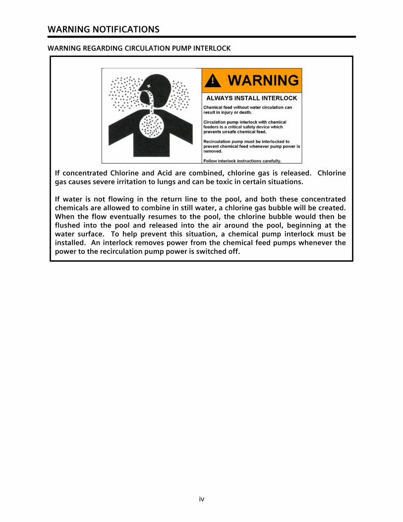
WARNING REGARDING CIRCULATION PUMP INTERLOCK
If concentrated Chlorine and Acid are combined, chlorine gas is released. Chlorine gas causes severe irritation to lungs and can be toxic in certain situations.
If water is not flowing in the return line to the pool, and both these concentrated chemicals are allowed to combine in still water, a chlorine gas bubble will be created. When the flow eventually resumes to the pool, the chlorine bubble would then be flushed into the pool and released into the air around the pool, beginning at the water surface. To help prevent this situation, a chemical pump interlock must be installed. An interlock removes power from the chemical feed pumps whenever the power to the recirculation pump power is switched off.
WARNING NOTIFICATIONS
v
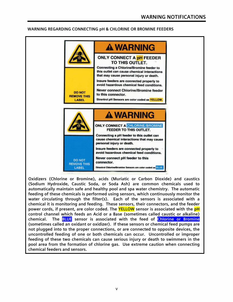
WARNING REGARDING CONNECTING pH & CHLORINE OR BROMINE FEEDERS
Oxidizers (Chlorine or Bromine), acids (Muriatic or Carbon Dioxide) and caustics (Sodium Hydroxide, Caustic Soda, or Soda Ash) are common chemicals used to automatically maintain safe and healthy pool and spa water chemistry. The automatic feeding of these chemicals is performed using sensors, which continuously monitor the water circulating through the filter(s). Each of the sensors is associated with a chemical it is monitoring and feeding. These sensors, their connectors, and the feeder power cords, if present, are color coded. The YELLOW sensor is associated with the pH control channel which feeds an Acid or a Base (sometimes called caustic or alkaline) chemical. The BLUE sensor is associated with the feed of Chlorine or Bromine (sometimes called an oxidant or oxidizer). If these sensors or chemical feed pumps are not plugged into to the proper connections, or are connected to opposite devices, the uncontrolled feeding of one or both chemicals can occur. Uncontrolled or improper feeding of these two chemicals can cause serious injury or death to swimmers in the pool area from the formation of chlorine gas. Use extreme caution when connecting chemical feeders and sensors.

Mounting – Chapter 1
1
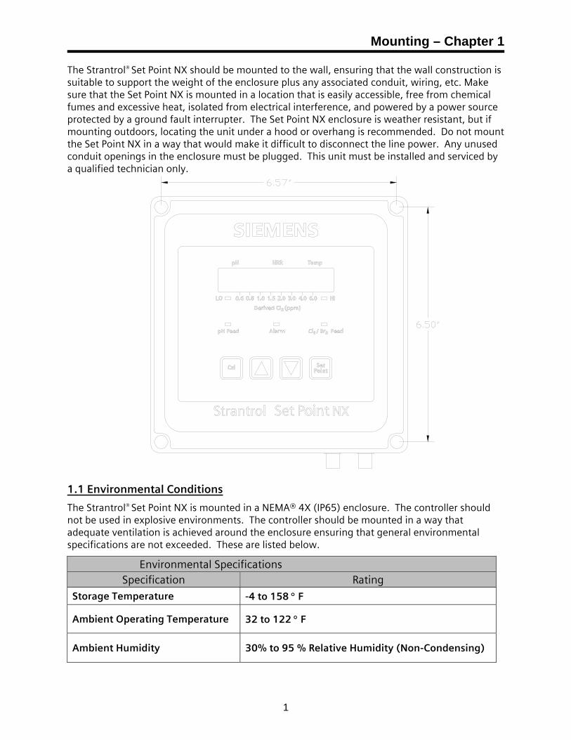
The Strantrol® Set Point NX should be mounted to the wall, ensuring that the wall construction is suitable to support the weight of the enclosure plus any associated conduit, wiring, etc. Make sure that the Set Point NX is mounted in a location that is easily accessible, free from chemical fumes and excessive heat, isolated from electrical interference, and powered by a power source protected by a ground fault interrupter. The Set Point NX enclosure is weather resistant, but if mounting outdoors, locating the unit under a hood or overhang is recommended. Do not mount the Set Point NX in a way that would make it difficult to disconnect the line power. Any unused conduit openings in the enclosure must be plugged. This unit must be installed and serviced by a qualified technician only.
1.1 Environmental Conditions
The Strantrol® Set Point NX is mounted in a NEMA® 4X (IP65) enclosure. The controller should not be used in explosive environments. The controller should be mounted in a way that adequate ventilation is achieved around the enclosure ensuring that general environmental specifications are not exceeded. These are listed below.
Environmental Specifications Specification Rating
Storage Temperature -4 to 158 ° F
Ambient Operating Temperature 32 to 122 ° F
Ambient Humidity 30% to 95 % Relative Humidity (Non-Condensing)

Plumbing – Chapter 2
3
2.1 Sample Stream General Recommendations and Precautions
The Strantrol® sample flow switch is provided solely for the sample flow “enable” signal to the Strantrol® controller. The flow switch provided is for the protection of swimmers when the sample stream flow stops. In this situation, the Strantrol® is designed to stop the feed of chemicals and indicate a “No-Flow” Alarm to alert the operator that the sample stream is not flowing and automatic control has been interrupted. Under normal conditions the flow switch, when closed, (in the “sample flow active” position) signals the Strantrol® that the sample is flowing and that automatic control can resume.
Siemens Water Technologies recommends, and good facilities design dictates that an additional safety device also be installed. To avoid the formation of gaseous chlorine when concentrated Chlorine and acidic chemicals are combined in a stopped water line, a flow switch must be installed in the water line accepting the chemical injection. The filter circulation return piping is typically the place where this occurs. When this line slows or stops flowing at the normal rate, a flow switch must be installed and wired so that it will then interrupt the feed of chemicals. This safety device should be installed whether or not automated controls are connected to the chemical pumps.
In many cases, the Strantrol® supplied sample flow switch is used as the only flow switch for the entire control system. If plumbed and connected properly, this arrangement can perform both tasks safely and reliably. If the water flow slows or stops in the water line where chemicals are being injected, all chemical feed must be prevented. Chemical feed must also be interrupted in the event of the sample stream being interrupted or slowed. It is the responsibility of the installer to assure the safe installation and operation of both the return line and sample stream flow switches.
The recommended installation diagrams in Appendix A illustrate how a single flow switch can be plumbed to perform both tasks. If the recommended installation cannot be accomplished due to site specific or application limitations, an additional return line flow switch must be installed to protect the people in the pool area.
Particular care should be taken during equipment installation or replacement, to assure these devices are plumbed, wired and functioning properly. The safety of the swimmers is also dependent upon the regular testing of these devices to assure they are in good working order. A good time to test these devices is whenever a filter backwash or any probe or sample flowcell maintenance is performed.
2.2 Assembling the Flowcell (Drawing Appendix A)
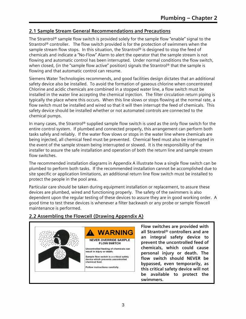
Flow switches are provided with all Strantrol® controllers and are an integral safety device to prevent the uncontrolled feed of chemicals, which could cause personal injury or death. The flow switch should NEVER be bypassed, even temporarily, as this critical safety device will not be available to protect the swimmers.
Technical Guide
4
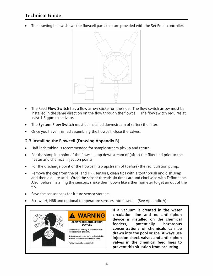
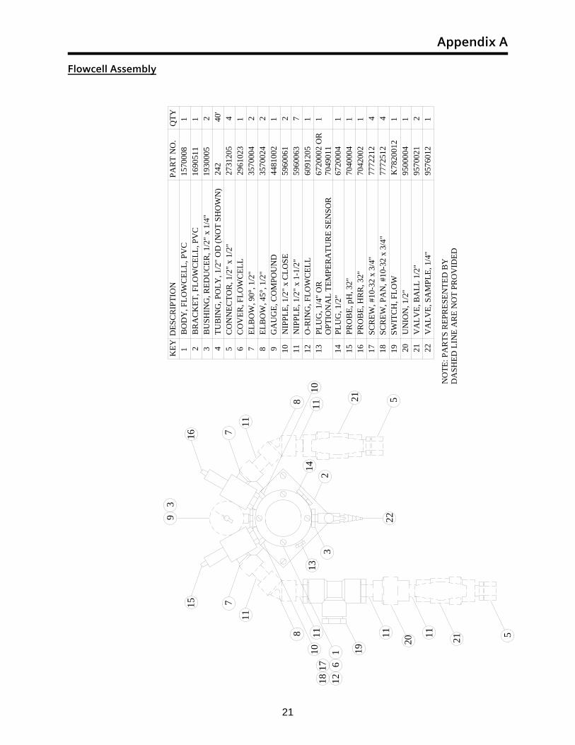
• The drawing below shows the flowcell parts that are provided with the Set Point controller.
• The Reed Flow Switch has a flow arrow sticker on the side. The flow switch arrow must be installed in the same direction on the flow through the flowcell. The flow switch requires at least 1.5 gpm to activate.
• The System Flow Switch must be installed downstream of (after) the filter.
• Once you have finished assembling the flowcell, close the valves. 2.3 Installing the Flowcell (Drawing Appendix B)
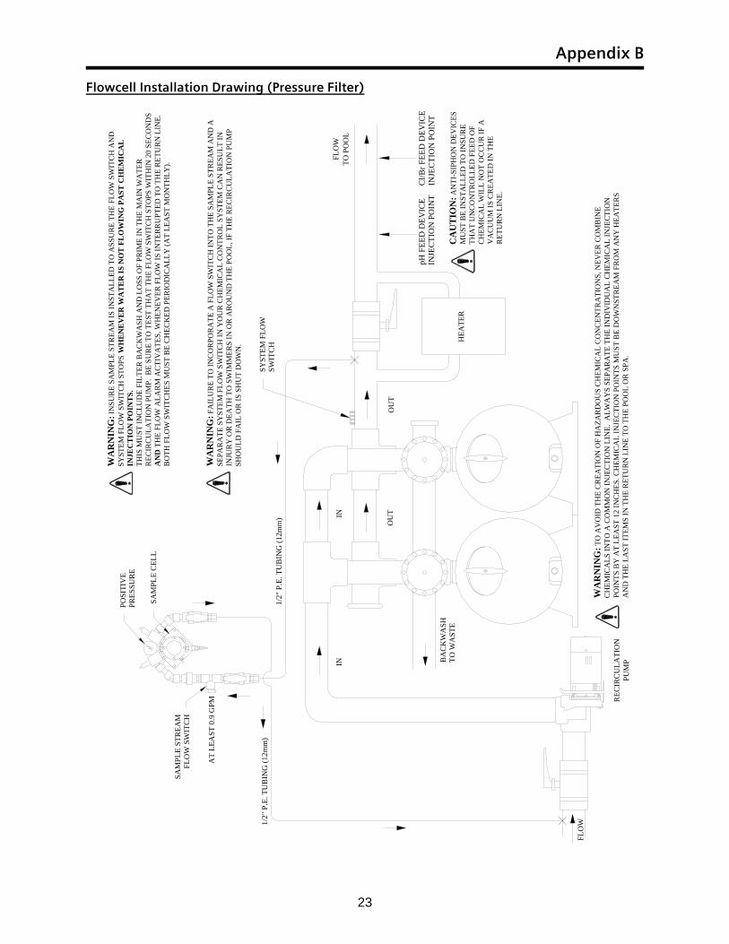
• Half-inch tubing is recommended for sample stream pickup and return.
• For the sampling point of the flowcell, tap downstream of (after) the filter and prior to the heater and chemical injection points.
• For the discharge point of the flowcell, tap upstream of (before) the recirculation pump.
• Remove the cap from the pH and HRR sensors, clean tips with a toothbrush and dish soap and then a dilute acid. Wrap the sensor threads six times around clockwise with Teflon tape. Also, before installing the sensors, shake them down like a thermometer to get air out of the tip.
• Save the sensor caps for future sensor storage.
• Screw pH, HRR and optional temperature sensors into flowcell. (See Appendix A)
If a vacuum is created in the water circulation line and no anti-siphon device is installed on the chemical feeders, potentially hazardous concentrations of chemicals can be drawn into the pool or spa. Always use injection check valves and anti-siphon valves in the chemical feed lines to prevent this situation from occurring.
Plumbing – Chapter 2
5
2.4 Checking the Flowcell
• Open the sample stream valves and check for leaks.
• Make sure the flowcell is under a positive and steady pressure.
• If not, adjust the valves, or if necessary relocate point at which the sample stream is connected to the recirculation system to ensure positive and steady pressure.
• Allow the sensors to rinse in the sample flowcell while you do the wiring.
• Open wet-test petcock and make sure that it generates a vigorous stream.
• Test flow switch function by closing the valve on the return line to the pool so that there is little or no flow to the pool. (Turning off the recirculation pump is not the same test)
• Assure the flow switch detects the low flow in the return line and the controller prohibits chemical feed.
• Test flow switch function by performing a filter backwash cycle.
• Assure the flow switch detects the low flow in the return line and prohibits chemical feed.
If any of the above tests do not pass, then the installation wiring or plumbing must be corrected, or additional safeguards must be installed. (Additional return line flow switch, etc.)
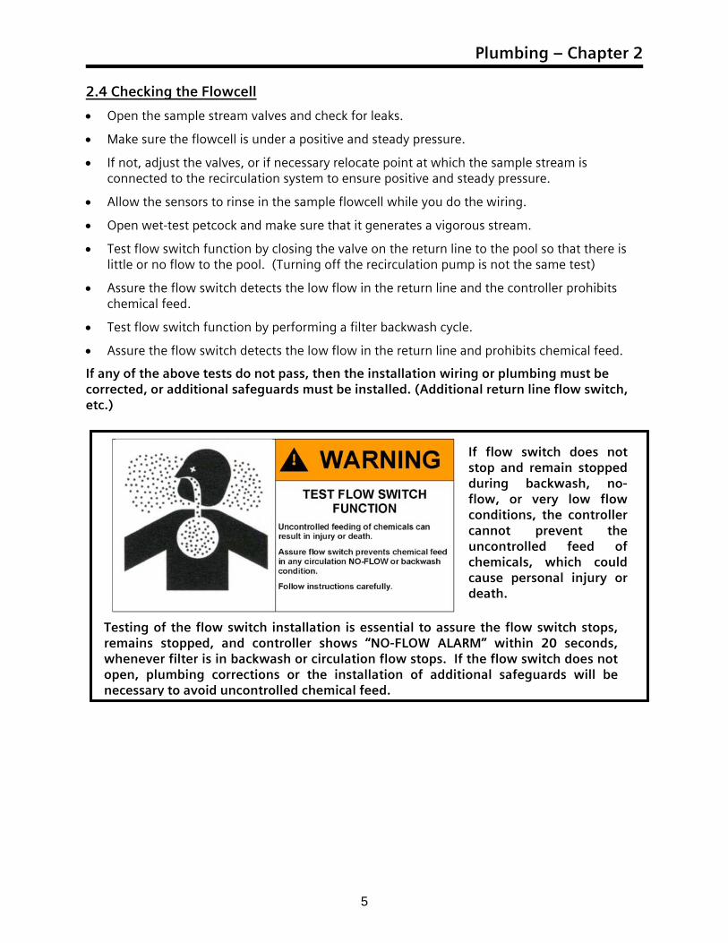
Testing of the flow switch installation is essential to assure the flow switch stops, remains stopped, and controller shows “NO-FLOW ALARM” within 20 seconds, whenever filter is in backwash or circulation flow stops. If the flow switch does not open, plumbing corrections or the installation of additional safeguards will be necessary to avoid uncontrolled chemical feed.
If flow switch does not stop and remain stopped during backwash, no-flow, or very low flow conditions, the controller cannot prevent the uncontrolled feed of chemicals, which could cause personal injury or death.

Hardware – Chapter 3
7
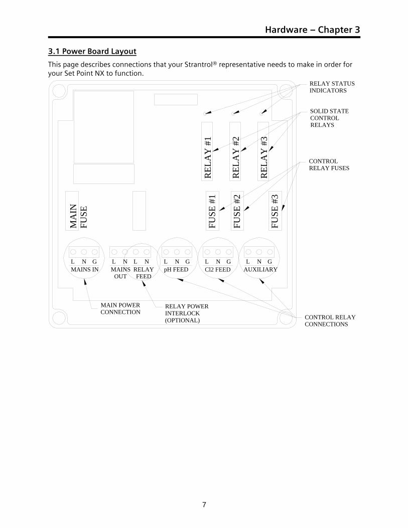
3.1 Power Board Layout
This page describes connections that your Strantrol® representative needs to make in order for your Set Point NX to function.
SOLID STATECONTROLRELAYS
REL
AY
#1
REL
AY
#2
REL
AY
#3
FUSE
#1
FUSE
#2
FUSE
#3
MA
INFU
SE
MAINS INL N G G
pH FEEDL N G
Cl2 FEEDL N G
AUXILIARYL N
CONTROL RELAYCONNECTIONS
CONTROLRELAY FUSES
MAIN POWERCONNECTION
RELAY STATUSINDICATORS
MAINSOUT
L LRELAYFEED
N N
RELAY POWERINTERLOCK(OPTIONAL)
Technical Guide
8
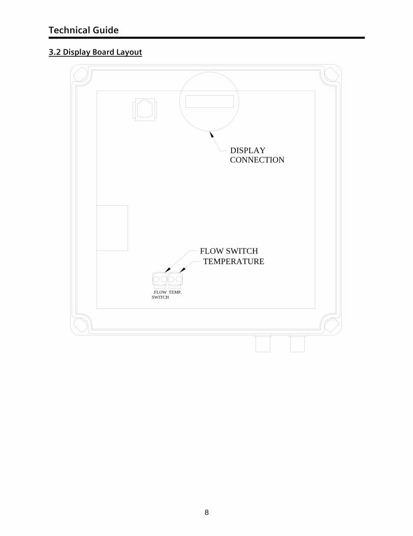
3.2 Display Board Layout
FLOW SWITCH
FLOWSWITCH
TEMP.
TEMPERATURE
DISPLAYCONNECTION
Electrical – Chapter 4
9
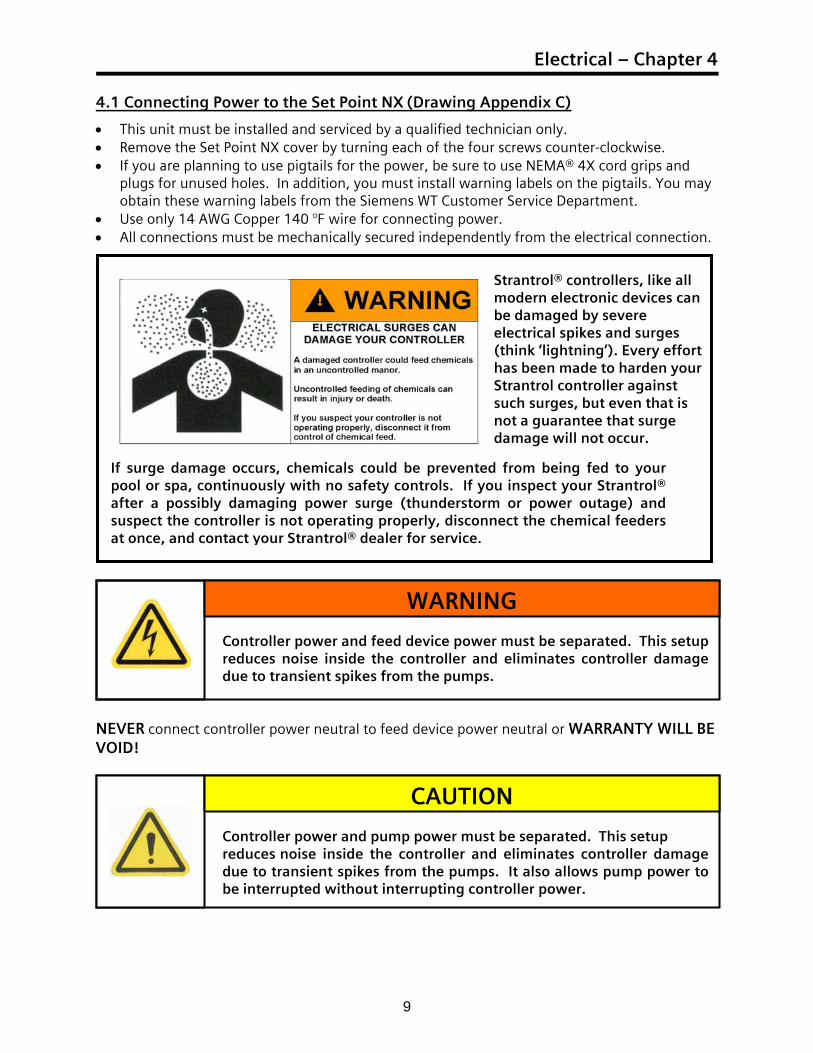
4.1 Connecting Power to the Set Point NX (Drawing Appendix C)
• This unit must be installed and serviced by a qualified technician only. • Remove the Set Point NX cover by turning each of the four screws counter-clockwise. • If you are planning to use pigtails for the power, be sure to use NEMA® 4X cord grips and
plugs for unused holes. In addition, you must install warning labels on the pigtails. You may obtain these warning labels from the Siemens WT Customer Service Department.
• Use only 14 AWG Copper 140 °F wire for connecting power. • All connections must be mechanically secured independently from the electrical connection.
NEVER connect controller power neutral to feed device power neutral or WARRANTY WILL BE VOID!
Controller power and pump power must be separated. This setup reduces noise inside the controller and eliminates controller damage due to transient spikes from the pumps. It also allows pump power to be interrupted without interrupting controller power.
CAUTION
Controller power and feed device power must be separated. This setup reduces noise inside the controller and eliminates controller damage due to transient spikes from the pumps.
WARNING
If surge damage occurs, chemicals could be prevented from being fed to your pool or spa, continuously with no safety controls. If you inspect your Strantrol® after a possibly damaging power surge (thunderstorm or power outage) and suspect the controller is not operating properly, disconnect the chemical feeders at once, and contact your Strantrol® dealer for service.
Strantrol® controllers, like all modern electronic devices can be damaged by severe electrical spikes and surges (think ‘lightning’). Every effort has been made to harden your Strantrol controller against such surges, but even that is not a guarantee that surge damage will not occur.
Technical Guide
10
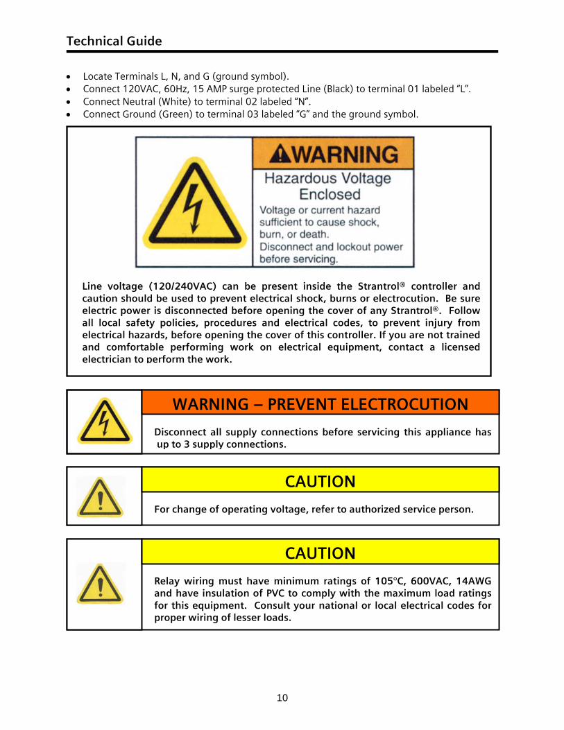
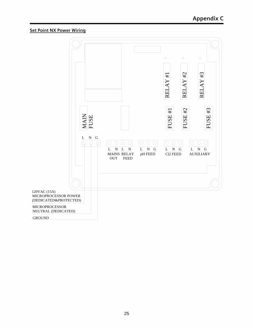
• Locate Terminals L, N, and G (ground symbol). • Connect 120VAC, 60Hz, 15 AMP surge protected Line (Black) to terminal 01 labeled “L”. • Connect Neutral (White) to terminal 02 labeled “N”. • Connect Ground (Green) to terminal 03 labeled “G” and the ground symbol.
Disconnect all supply connections before servicing this appliance has up to 3 supply connections.
WARNING – PREVENT ELECTROCUTION
For change of operating voltage, refer to authorized service person.
CAUTION
Relay wiring must have minimum ratings of 105°C, 600VAC, 14AWG and have insulation of PVC to comply with the maximum load ratings for this equipment. Consult your national or local electrical codes for proper wiring of lesser loads.
CAUTION
Line voltage (120/240VAC) can be present inside the Strantrol® controller and caution should be used to prevent electrical shock, burns or electrocution. Be sure electric power is disconnected before opening the cover of any Strantrol®. Follow all local safety policies, procedures and electrical codes, to prevent injury from electrical hazards, before opening the cover of this controller. If you are not trained and comfortable performing work on electrical equipment, contact a licensed electrician to perform the work.
Electrical – Chapter 4
11
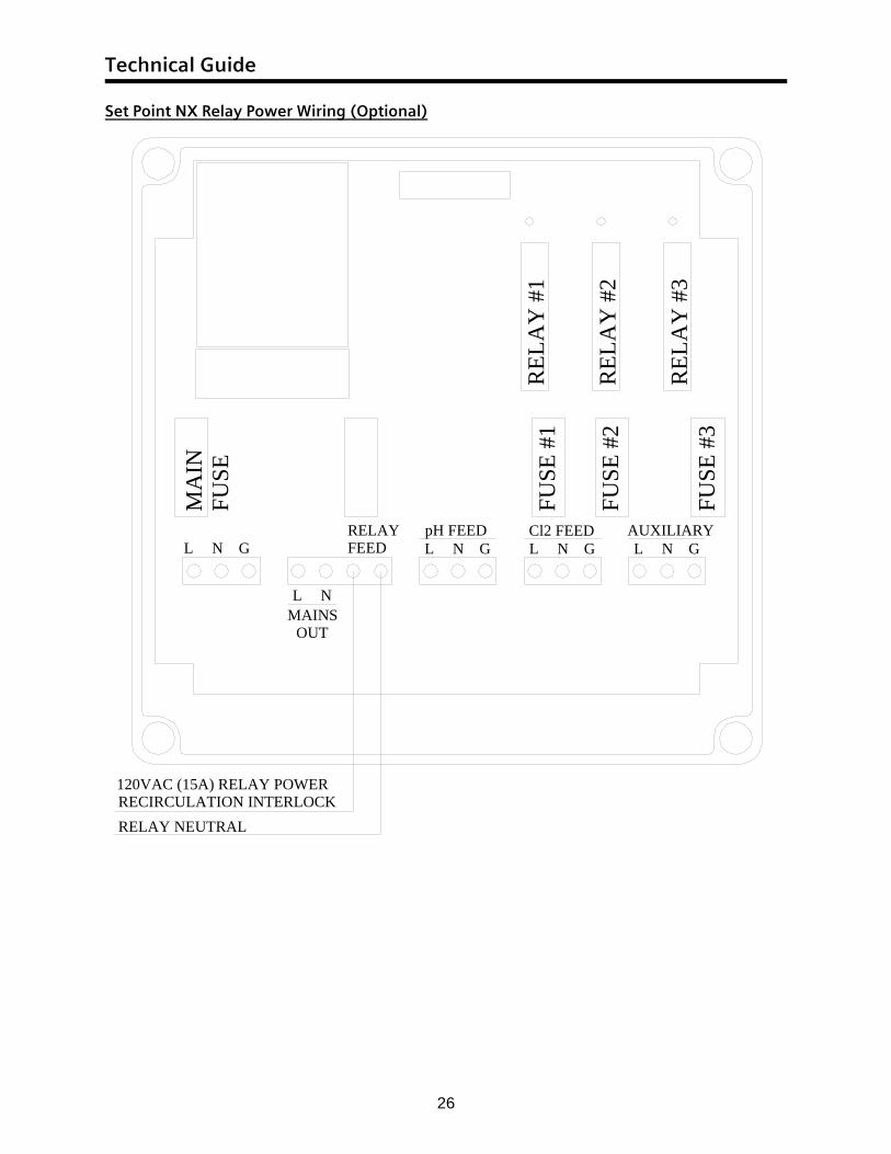
4.2 Optional: Interlocking Power to Set Point NX Feed Relays (Drawing Appendix C)
From the factory the relay power is connected the Set Point NX’s main power via the brown and blue jumpers. If relay interlock is required the Set Point NX relay power can be configured to be interlock with the main recirculation pump. Recirculation pump interlock provides more protection from feeding chemicals during a no flow condition.
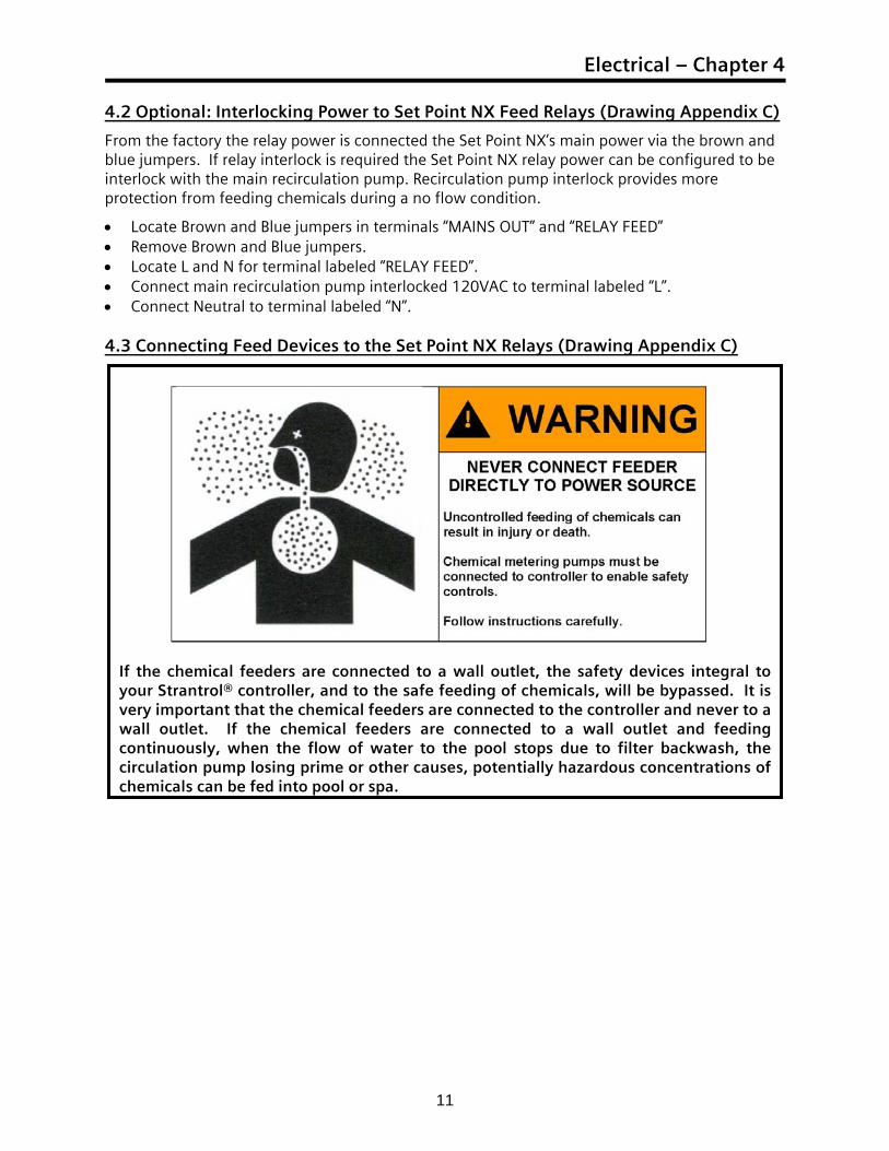
• Locate Brown and Blue jumpers in terminals “MAINS OUT” and “RELAY FEED” • Remove Brown and Blue jumpers. • Locate L and N for terminal labeled “RELAY FEED”. • Connect main recirculation pump interlocked 120VAC to terminal labeled “L”. • Connect Neutral to terminal labeled “N”. 4.3 Connecting Feed Devices to the Set Point NX Relays (Drawing Appendix C)
If the chemical feeders are connected to a wall outlet, the safety devices integral to your Strantrol® controller, and to the safe feeding of chemicals, will be bypassed. It is very important that the chemical feeders are connected to the controller and never to a wall outlet. If the chemical feeders are connected to a wall outlet and feeding continuously, when the flow of water to the pool stops due to filter backwash, the circulation pump losing prime or other causes, potentially hazardous concentrations of chemicals can be fed into pool or spa.
Technical Guide
12
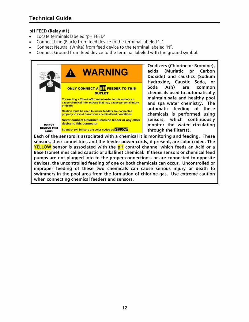
Each of the sensors is associated with a chemical it is monitoring and feeding. These sensors, their connectors, and the feeder power cords, if present, are color coded. The YELLOW sensor is associated with the pH control channel which feeds an Acid or a Base (sometimes called caustic or alkaline) chemical. If these sensors or chemical feed pumps are not plugged into to the proper connections, or are connected to opposite devices, the uncontrolled feeding of one or both chemicals can occur. Uncontrolled or improper feeding of these two chemicals can cause serious injury or death to swimmers in the pool area from the formation of chlorine gas. Use extreme caution when connecting chemical feeders and sensors.
Oxidizers (Chlorine or Bromine), acids (Muriatic or Carbon Dioxide) and caustics (Sodium Hydroxide, Caustic Soda, or Soda Ash) are common chemicals used to automatically maintain safe and healthy pool and spa water chemistry. The automatic feeding of these chemicals is performed using sensors, which continuously monitor the water circulating through the filter(s).
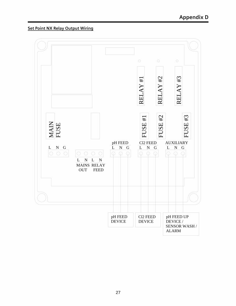
pH FEED (Relay #1) • Locate terminals labeled “pH FEED” • Connect Line (Black) from feed device to the terminal labeled “L”. • Connect Neutral (White) from feed device to the terminal labeled “N”. • Connect Ground from feed device to the terminal labeled with the ground symbol.
Electrical – Chapter 4
13
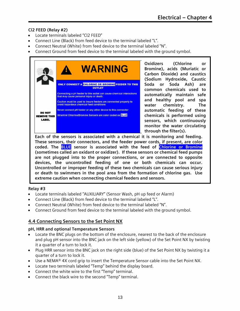
Cl2 FEED (Relay #2) • Locate terminals labeled “Cl2 FEED” • Connect Line (Black) from feed device to the terminal labeled “L”. • Connect Neutral (White) from feed device to the terminal labeled “N”. • Connect Ground from feed device to the terminal labeled with the ground symbol.
Relay #3 • Locate terminals labeled “AUXILIARY” (Sensor Wash, pH up feed or Alarm) • Connect Line (Black) from feed device to the terminal labeled “L”. • Connect Neutral (White) from feed device to the terminal labeled “N”. • Connect Ground from feed device to the terminal labeled with the ground symbol. 4.4 Connecting Sensors to the Set Point NX
pH, HRR and optional Temperature Sensors • Locate the BNC plugs on the bottom of the enclosure, nearest to the back of the enclosure
and plug pH sensor into the BNC jack on the left side (yellow) of the Set Point NX by twisting it a quarter of a turn to lock it.
• Plug HRR sensor into the BNC jack on the right side (blue) of the Set Point NX by twisting it a quarter of a turn to lock it.
• Use a NEMA® 4X cord grip to insert the Temperature Sensor cable into the Set Point NX. • Locate two terminals labeled “Temp” behind the display board. • Connect the white wire to the first “Temp” terminal. • Connect the black wire to the second “Temp” terminal.
Each of the sensors is associated with a chemical it is monitoring and feeding. These sensors, their connectors, and the feeder power cords, if present, are color coded. The BLUE sensor is associated with the feed of Chlorine or Bromine (sometimes called an oxidant or oxidizer). If these sensors or chemical feed pumps are not plugged into to the proper connections, or are connected to opposite devices, the uncontrolled feeding of one or both chemicals can occur. Uncontrolled or improper feeding of these two chemicals can cause serious injury or death to swimmers in the pool area from the formation of chlorine gas. Use extreme caution when connecting chemical feeders and sensors.
Oxidizers (Chlorine or Bromine), acids (Muriatic or Carbon Dioxide) and caustics (Sodium Hydroxide, Caustic Soda or Soda Ash) are common chemicals used to automatically maintain safe and healthy pool and spa water chemistry. The automatic feeding of these chemicals is performed using sensors, which continuously monitor the water circulating through the filter(s).
Technical Guide
14
4.5 Connecting Flow Switches to the Set Point NX
Once both the sample stream and system flow switches have been installed following the instructions in the plumbing section, the electrical connections will need to be made.
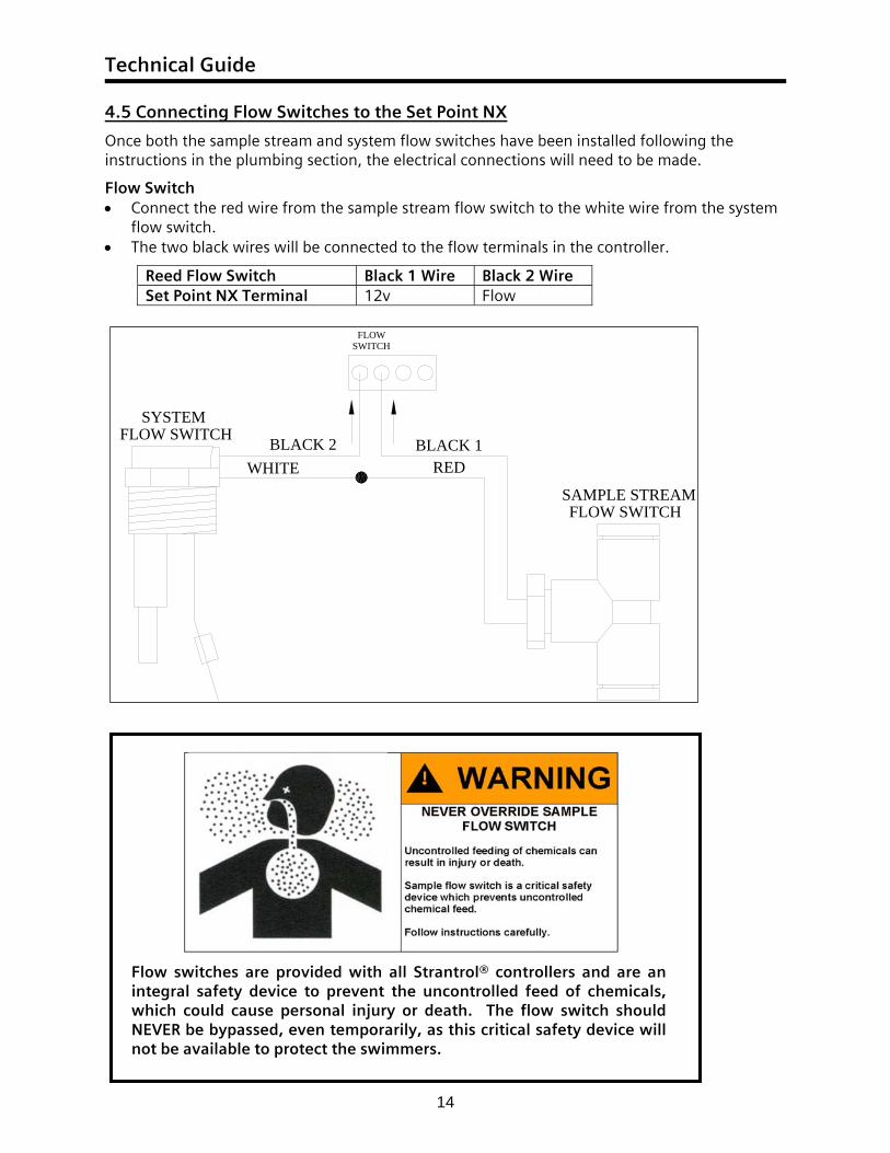
Flow Switch • Connect the red wire from the sample stream flow switch to the white wire from the system
flow switch. • The two black wires will be connected to the flow terminals in the controller.
Reed Flow Switch Black 1 Wire Black 2 Wire Set Point NX Terminal 12v Flow
FLOWSWITCH
SYSTEMFLOW SWITCH BLACK 2
WHITEBLACK 1
RED
FLOW SWITCHSAMPLE STREAM
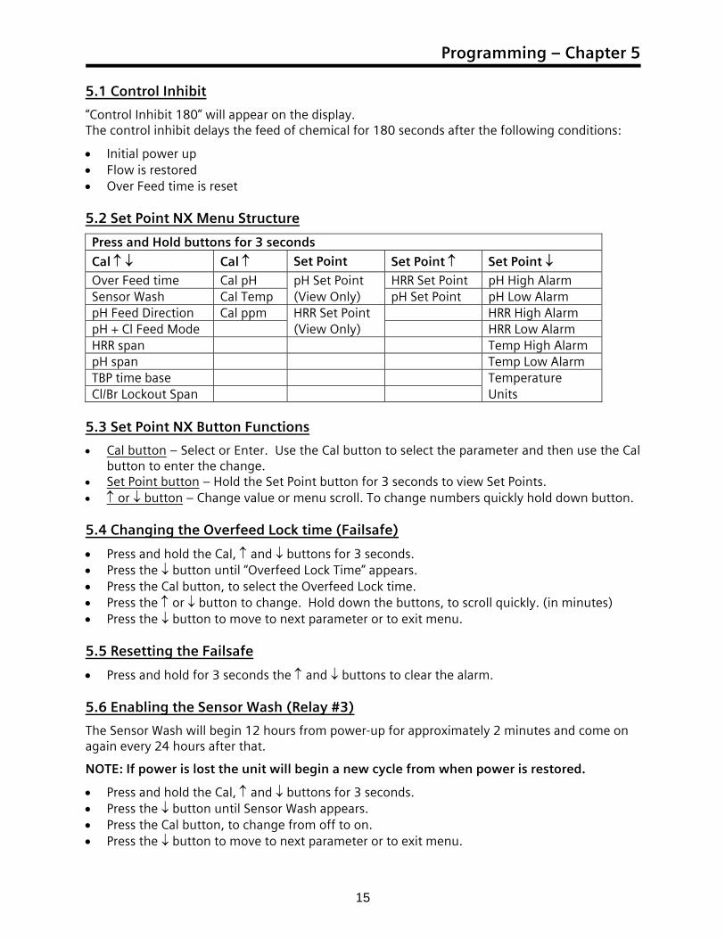
Flow switches are provided with all Strantrol® controllers and are an integral safety device to prevent the uncontrolled feed of chemicals, which could cause personal injury or death. The flow switch should NEVER be bypassed, even temporarily, as this critical safety device will not be available to protect the swimmers.
Programming – Chapter 5
15
5.1 Control Inhibit
“Control Inhibit 180” will appear on the display. The control inhibit delays the feed of chemical for 180 seconds after the following conditions:
• Initial power up • Flow is restored • Over Feed time is reset 5.2 Set Point NX Menu Structure
Press and Hold buttons for 3 seconds Cal ↑ ↓ Cal ↑ Set Point Set Point ↑ Set Point ↓ Over Feed time Cal pH pH Set Point HRR Set Point pH High Alarm Sensor Wash Cal Temp (View Only) pH Set Point pH Low Alarm pH Feed Direction Cal ppm HRR Set Point HRR High Alarm pH + Cl Feed Mode (View Only) HRR Low Alarm HRR span Temp High Alarm pH span Temp Low Alarm TBP time base Temperature Cl/Br Lockout Span Units
5.3 Set Point NX Button Functions
• Cal button – Select or Enter. Use the Cal button to select the parameter and then use the Cal button to enter the change.
• Set Point button – Hold the Set Point button for 3 seconds to view Set Points. • ↑ or ↓ button – Change value or menu scroll. To change numbers quickly hold down button. 5.4 Changing the Overfeed Lock time (Failsafe)
• Press and hold the Cal, ↑ and ↓ buttons for 3 seconds. • Press the ↓ button until “Overfeed Lock Time” appears. • Press the Cal button, to select the Overfeed Lock time. • Press the ↑ or ↓ button to change. Hold down the buttons, to scroll quickly. (in minutes) • Press the ↓ button to move to next parameter or to exit menu. 5.5 Resetting the Failsafe
• Press and hold for 3 seconds the ↑ and ↓ buttons to clear the alarm. 5.6 Enabling the Sensor Wash (Relay #3)
The Sensor Wash will begin 12 hours from power-up for approximately 2 minutes and come on again every 24 hours after that.
NOTE: If power is lost the unit will begin a new cycle from when power is restored.
• Press and hold the Cal, ↑ and ↓ buttons for 3 seconds. • Press the ↓ button until Sensor Wash appears. • Press the Cal button, to change from off to on. • Press the ↓ button to move to next parameter or to exit menu.
Technical Guide
16
5.7 Changing the pH Feed Direction
• Press and hold the Cal, ↑ and ↓ buttons for 3 seconds. • Press the ↓ button until pH Feed Chemical appears. • Press the Cal button, to change from Acid (pH down) to Acid + Alkali (pH down and up) or to
Alkali (pH up). • Press the ↓ button to move to next parameter or to exit menu.
Note: If Acid + Alkali is chosen Relay #1 will be Acid and Relay #3 will be Alkali. 5.8 Auxiliary Relay (Relay #3)
The auxiliary relay can be either Sensor Wash, pH feed up or Alarm. 5.9 Changing Feed Modes (ON/OFF or Time Based Proportional)
On/Off should be chosen for motor-driven chemical feeders and Time Based Proportional should be chosen for solenoid-driven or pulsed-diaphragm chemical feeders.
On/Off – (Feed down or up) When the measurement crosses this setpoint value, the chemical feed activates, and feeds continuously until the measurement returns to a point below or above setpoint.
Time Based Proportional (TBP) – (Feed down or up) TBP will adjust the feed of chemical proportionately based upon how far the measurement is above or below setpoint. This is done by turning on and off feeder power for portions of a one-minute time-base. As the measurement rises or falls even further from setpoint, the ratio of on and off times changes to increase the amount of chemical per minute dispensed.
• Press and hold the Cal, ↑ and ↓ buttons for 3 seconds. • Press the ↓ button until “Control Type” appears. • Press the Cal button, to change the type of control. • Press the ↓ button to exit the menu. 5.10 Changing TBP span
The span should be increased if the feed is too much or decreased if the feed is not enough.
• Press and hold the Cal, ↑ and ↓ buttons for 3 seconds. • Press the ↓ button until desired span appears. • Press the Cal button, to select the span. • Press the ↑ or ↓ button to change. • Press the Cal button to enter value. • Press the ↓ button to move to next parameter or to exit menu. 5.11 Changing TBP Time Base
The Time Base is the total time of the on and off time.
• Press and hold the Cal, ↑ and ↓ buttons for 3 seconds. • Press the ↓ button until desired span appears. • Press the Cal button, to select the span. • Press the ↑ or ↓ button to change. • Press the Cal button, to enter value. • Press the ↓ button to move to next parameter or to exit menu.
Programming – Chapter 5
17
5.12 Changing Cl/Br Lockout span
The Cl/Br Lockout span is the distance from the pH setpoint in which the Set Point NX will lockout the chlorine feed. Example: Setpoint = 7.5, Cl/Br Lockout span = 0.5, the chlorine will be locked out at 7.0 and 8.0.
• Press and hold the Cal, ↑ and ↓ buttons for 3 seconds. • Press the ↓ button until desired Cl/Br Lockout span appears. • Press the Cal button, to select. • Press the ↑ or ↓ button to change. • Press the Cal button, to enter value. • Press the ↓ button to move to next parameter or to exit menu. 5.13 Changing the Sensor Calibration
• Press and hold the Cal and ↑ buttons for 3 seconds. • Press the ↓ button, until the desired parameter appears. • Press the Cal button, to select parameter calibration. • Press the ↑ or ↓ button, to change calibration. • Press the Cal button, to enter calibration. • Press the ↓ button to move to next parameter or to exit menu 5.14 Viewing the Set Points
• Press and hold the Set Point button for 3 seconds • Press the ↓ button to move to next parameter or to exit menu 5.15 Viewing the Alarm Set Points
• Press and hold the Cal button for 3 seconds • Press the ↓ button to move to next parameter or to exit menu 5.16 Changing the Set Points
• Press and hold the Set Point and ↑ buttons for 3 seconds • Press the ↓ button, until the desired parameter appears. • Press the Cal button, to select parameter set point. • Press the ↑ or ↓ button, to change set point. • Press the Cal button, to enter set point. • Press the ↓ button to move to next parameter or to exit menu 5.17 Changing the Alarm Points
• Press and hold the Set Point and ↓ buttons • Press the ↓ button, until desired alarm point appears. • Press the Cal button, to select alarm point. • Press the ↑ or ↓ button to change alarm point. Hold down the buttons, to scroll quickly. • Press the Cal button, to enter alarm point. • Press the ↓ button to move to next alarm point or to exit menu
Technical Guide
18
5.18 Changing the Temperature Units
• Press and hold the Set Point and ↓ buttons • Press the ↓ button, until “Temp Sensor” appears. • Press the Cal button, to change units. • Press the ↓ button to move to next alarm point or to exit menu. 5.19 Alarm Messages
Alarm Message Cause
Overfeed Alarm pH and/or HRR measurements have failed to reach the set point within the overfeed lock time.
No Flow Alarm Indication of flow status.
Cl/BR Lockout Alarm pH measurement not within the pH alarm points.
Sensor Wash Sensor wash process active.
HRR High Alarm HRR measurement above high alarm setting.
HRR Low Alarm HRR measurement below low alarm setting.
pH High Alarm pH measurement above high alarm setting
pH Low Alarm pH measurement below low alarm setting
Temp High Alarm Temperature measurement above high alarm setting
Temp Low Alarm Temperature measurement below low alarm setting
Maintenance – Chapter 6
19
6.1 Cleaning the Sensors
The Set Point NX requires no maintenance other than a periodic calibration check and sensor cleaning.
1. Isolate the Flowcell, and then remove the sensors. 2. Clean the tips with HRR® Cleaning Solution and a toothbrush. 3. Check Teflon® sealing tape on threads and reinstall sensor. 4. Open valves and let sensors rinse for 15 minutes in sample stream water before making
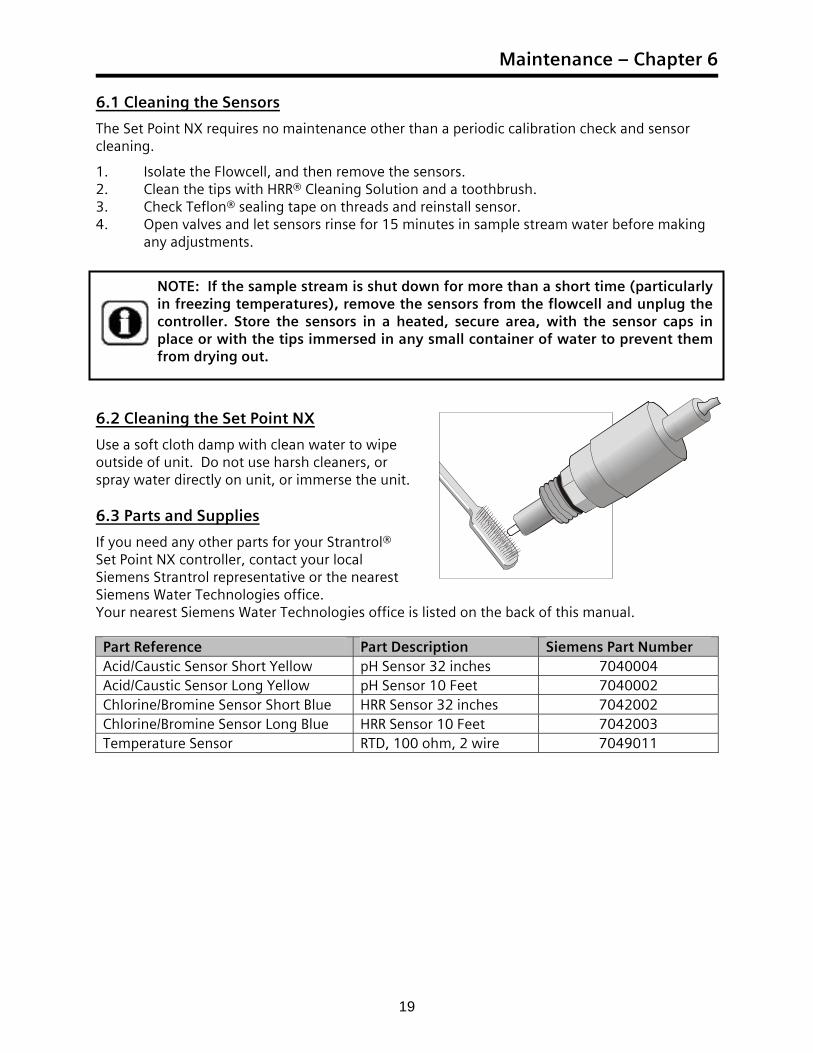
any adjustments. 6.2 Cleaning the Set Point NX
Use a soft cloth damp with clean water to wipe outside of unit. Do not use harsh cleaners, or spray water directly on unit, or immerse the unit. 6.3 Parts and Supplies
If you need any other parts for your Strantrol® Set Point NX controller, contact your local Siemens Strantrol representative or the nearest Siemens Water Technologies office. Your nearest Siemens Water Technologies office is listed on the back of this manual. Part Reference Part Description Siemens Part Number Acid/Caustic Sensor Short Yellow pH Sensor 32 inches 7040004 Acid/Caustic Sensor Long Yellow pH Sensor 10 Feet 7040002 Chlorine/Bromine Sensor Short Blue HRR Sensor 32 inches 7042002 Chlorine/Bromine Sensor Long Blue HRR Sensor 10 Feet 7042003 Temperature Sensor RTD, 100 ohm, 2 wire 7049011
NOTE: If the sample stream is shut down for more than a short time (particularly in freezing temperatures), remove the sensors from the flowcell and unplug the controller. Store the sensors in a heated, secure area, with the sensor caps in place or with the tips immersed in any small container of water to prevent them from drying out.

Appendix A
21
Flowcell Assembly
BO
DY
, FLO
WC
ELL,
PV
C1
1570
008
116
9051
1B
RA
CK
ET, F
LOW
CEL
L, P
VC
21
1930
005
BU
SHIN
G, R
EDU
CER
, 1/2
" x
1/4"
32
242
TUB
ING
, PO
LY, 1
/2" O
D (N
OT
SHO
WN
)4
40'
2731
205
CO
NN
ECTO
R, 1
/2"
x 1/
2"5
429
6102
3C
OV
ER, F
LOW
CEL
L6
135
7000
4EL
BO
W, 9
0°, 1
/2"
72
3570
024
ELB
OW
, 45°
, 1/2
"8
244
8100
2G
AU
GE,
CO
MPO
UN
D9
159
6006
1N
IPPL
E, 1
/2"
x C
LOSE
102
5960
063
117
6091
205
O-R
ING
, FLO
WC
ELL
121
6720
002
OR
70
4901
113
1
6720
004
PLU
G, 1
/2"
141
7040
004
PRO
BE,
pH
, 32"
151
7042
002
PRO
BE,
HR
R, 3
2"16
117
7772
212
SCR
EW, #
10-3
2 x
3/4"
184
7772
512
SCR
EW, P
AN
, #10
-32
x 3/
4"19
4K
7820
012
SWIT
CH
, FLO
W20
1
9570
021
212
VA
LVE,
BA
LL 1
/2"
22KEY
DES
CR
IPTI
ON
NIP
PLE,
1/2
" x
1-1/
2"
PAR
T N
O.
QTY
VA
LVE,
SA
MPL
E, 1
/4"
9576
012
1
UN
ION
, 1/2
"95
0000
41
12
3
5
5
6
77
88
93
10
1111 11
11
11
121817
11
1516
14
19
20 21
21
22
1310
NO
TE: P
AR
TS R
EPR
ESEN
TED
BY
D
ASH
ED L
INE
AR
E N
OT
PRO
VID
ED
PLU
G, 1
/4"
OR
O
PTIO
NA
L TE
MPE
RA
TUR
E SE
NSO
R

Appendix B
23
Flowcell Installation Drawing (Pressure Filter)
WA
RN
ING
: FA
ILU
RE
TO IN
CO
RPO
RA
TE A
FLO
W S
WIT
CH
INTO
TH
E SA
MPL
E ST
REA
M A
ND
A
SEPA
RA
TE S
YST
EM F
LOW
SW
ITC
H IN
YO
UR
CH
EMIC
AL
CO
NTR
OL
SYST
EM C
AN
RES
ULT
IN
INJU
RY
OR
DEA
TH T
O S
WIM
MER
S IN
OR
AR
OU
ND
TH
E PO
OL,
IF T
HE
REC
IRC
ULA
TIO
N P
UM
P SH
OU
LD F
AIL
OR
IS S
HU
T D
OW
N.
FLO
W
REC
IRC
ULA
TIO
NPU
MPB
AC
KW
ASH
TO W
AST
E
IN
OU
TIN
CA
UT
ION
: AN
TI-S
IPH
ON
DEV
ICES
M
UST
BE
INST
ALL
ED T
O IN
SUR
E TH
AT
UN
CO
NTR
OLL
ED F
EED
OF
CH
EMIC
AL
WIL
L N
OT
OC
CU
R IF
A
VA
CU
UM
IS C
REA
TED
IN T
HE
RET
UR
N L
INE.
HEA
TER
pH F
EED
DEV
ICE
INJE
CTI
ON
PO
INT
Cl/B
r FEE
D D
EVIC
EIN
JEC
TIO
N P
OIN
T
WA
RN
ING
: TO
AV
OID
TH
E C
REA
TIO
N O
F H
AZA
RD
OU
S C
HEM
ICA
L C
ON
CEN
TRA
TIO
NS,
NEV
ER C
OM
BIN
E C
HEM
ICA
LS IN
TO A
CO
MM
ON
INJE
CTI
ON
LIN
E. A
LWA
YS
SEPA
RA
TE T
HE
IND
IVID
UA
L C
HEM
ICA
L IN
JEC
TIO
N
POIN
TS B
Y A
T LE
AST
12
INC
HES
. CH
EMIC
AL
INJE
CTI
ON
PO
INTS
MU
ST B
E D
OW
NST
REA
M F
RO
M A
NY
HEA
TER
S A
ND
TH
E LA
ST IT
EMS
IN T
HE
RET
UR
N L
INE
TO T
HE
POO
L O
R S
PA.
WA
RN
ING
: IN
SUR
E SA
MPL
E ST
REA
M IS
INST
ALL
ED T
O A
SSU
RE
THE
FLO
W S
WIT
CH
AN
D
SYST
EM F
LOW
SW
ITC
H S
TOPS
WH
EN
EV
ER
WA
TE
R I
S N
OT
FL
OW
ING
PA
ST C
HE
MIC
AL
IN
JEC
TIO
N P
OIN
TS.
THIS
MU
ST IN
CLU
DE
FILT
ER B
AC
KW
ASH
AN
D L
OSS
OF
PRIM
E IN
TH
E M
AIN
WA
TER
R
ECIR
CU
LATI
ON
PU
MP.
BE
SUR
E TO
TES
T TH
AT
THE
FLO
W S
WIT
CH
STO
PS W
ITH
IN 2
0 SE
CO
ND
S A
ND
TH
E FL
OW
ALA
RM
AC
TIV
ATE
S, W
HEN
EVER
FLO
W IS
INTE
RR
UPT
ED T
O T
HE
RET
UR
N L
INE.
B
OTH
FLO
W S
WIT
CH
ES M
UST
BE
CH
ECK
ED P
ERIO
DIC
ALL
Y (A
T LE
AST
MO
NTH
LY).
OU
T
FLO
WTO
PO
OL
SYST
EM F
LOW
SW
ITC
H
AT
LEA
ST 0
.9 G
PM
1/2"
P.E
. TU
BIN
G (1
2mm
)
SAM
PLE
STR
EAM
FLO
W S
WIT
CH
SAM
PLE
CEL
L
POSI
TIV
EPR
ESSU
RE
1/2"
P.E
. TU
BIN
G (1
2mm
)
Technical Guide
24
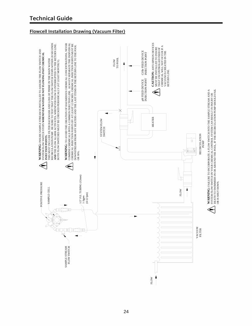
Flowcell Installation Drawing (Vacuum Filter)
WA
RN
ING
: FA
ILU
RE
TO IN
CO
RPO
RA
TE A
FLO
W S
WIT
CH
INTO
TH
E SA
MPL
E ST
REA
M A
ND
A
SYST
EM F
LOW
SW
ITC
H IN
YO
UR
CH
EMIC
AL
CO
NTR
OL
SYST
EM C
AN
RES
ULT
IN IN
JUR
Y O
R
DEA
TH T
O S
WIM
MER
S IN
OR
AR
OU
ND
TH
E PO
OL,
IF T
HE
REC
IRC
ULA
TIO
N P
UM
P SH
OU
LD F
AIL
O
R IS
SH
UT
DO
WN
.
(4-1
2 lp
m)
1/2"
P.E
. TU
BIN
G (1
2mm
)1-
3gpm
SAM
PLE
CEL
L
POSI
TIV
E PR
ESSU
RE
CA
UT
ION
: AN
TI-S
IPH
ON
DEV
ICES
M
UST
BE
INST
ALL
ED T
O IN
SUR
E TH
AT
UN
CO
NTR
OLL
ED F
EED
OF
CH
EMIC
AL
WIL
L N
OT
OC
CU
R IF
A
VA
CU
UM
IS C
REA
TED
IN T
HE
RET
UR
N L
INE.
pH F
EED
DEV
ICE
INJE
CTI
ON
PO
INT
Cl/B
r FEE
D D
EVIC
EIN
JEC
TIO
N P
OIN
T
WA
RN
ING
: TO
AV
OID
TH
E C
REA
TIO
N O
F H
AZA
RD
OU
S C
HEM
ICA
L C
ON
CEN
TRA
TIO
NS,
NEV
ER
CO
MB
INE
CH
EMIC
ALS
INTO
A C
OM
MO
N IN
JEC
TIO
N L
INE.
ALW
AY
S SE
PAR
ATE
TH
E IN
DIV
IDU
AL
CH
EMIC
AL
INJE
CTI
ON
PO
INTS
BY
AT
LEA
ST 1
2 IN
CH
ES. C
HEM
ICA
L IN
JEC
TIO
N P
OIN
TS M
UST
BE
DO
WN
STR
EAM
FR
OM
AN
Y H
EATE
RS
AN
D T
HE
LAST
ITEM
S IN
TH
E R
ETU
RN
LIN
E TO
TH
E PO
OL
OR
SPA
.
WA
RN
ING
: IN
SUR
E SA
MPL
E ST
REA
M IS
INST
ALL
ED T
O A
SSU
RE
THE
FLO
W S
WIT
CH
AN
D
SYST
EM F
LOW
SW
ITC
H S
TOPS
WH
EN
EV
ER
WA
TE
R IS
NO
T F
LO
WIN
G P
AST
CH
EM
ICA
L
INJE
CT
ION
PO
INT
S.TH
IS M
UST
INC
LUD
E FI
LTER
BA
CK
WA
SH A
ND
LO
SS O
F PR
IME
IN T
HE
MA
IN W
ATE
R
REC
IRC
ULA
TIO
N P
UM
P. B
E SU
RE
TO T
EST
THA
T TH
E FL
OW
SW
ITC
H S
TOPS
WIT
HIN
20
SEC
ON
DS
AN
D T
HE
FLO
W A
LAR
M A
CTI
VA
TES,
WH
ENEV
ER F
LOW
IS IN
TER
RU
PTED
TO
TH
E R
ETU
RN
LIN
E.
BO
TH F
LOW
SW
ITC
HES
MU
ST B
E C
HEC
KED
PER
IOD
ICA
LLY
(AT
LEA
ST M
ON
THLY
).
FLO
WTO
PO
OL
SYST
EM F
LOW
SW
ITC
H HEA
TER
FILT
ER
FLO
W
VA
CU
UM
FLO
W
REC
IRC
ULA
TIO
NPU
MP
SAM
PLE
STR
EAM
FLO
W S
WIT
CH
Appendix C
25
Set Point NX Power Wiring
REL
AY
#1
REL
AY
#2
REL
AY
#3
FUSE
#1
FUSE
#2
FUSE
#3
MA
INFU
SE
L N G
GpH FEEDL N G
Cl2 FEEDL N G
AUXILIARYL N
120VAC (15A)MICROPROCESSOR POWER(DEDICATED&PROTECTED)
MICROPROCESSORNEUTRAL (DEDICATED)
GROUND
NLRELAYFEED
MAINSOUT
L N
Technical Guide
26
Set Point NX Relay Power Wiring (Optional)
REL
AY
#1
REL
AY
#2
REL
AY
#3
FUSE
#1
FUSE
#2
FUSE
#3
MA
INFU
SE
L N G GpH FEEDL N G
Cl2 FEEDL N G
AUXILIARYL N
120VAC (15A) RELAY POWERRECIRCULATION INTERLOCKRELAY NEUTRAL
RELAYFEED
MAINSOUT
L N
Appendix D
27
Set Point NX Relay Output Wiring
REL
AY
#1
REL
AY
#2
REL
AY
#3
FUSE
#1
FUSE
#2
FUSE
#3
MA
INFU
SE
L N G GpH FEEDL N G
Cl2 FEEDL N G
AUXILIARYL N
pH FEEDDEVICE
Cl2 FEEDDEVICE
pH FEED UPDEVICE / SENSOR WASH / ALARM
MAINSOUT
LRELAYFEED
LN N


Stranco and High Resolution Redox are trademarks of Siemens, its subsidiaries or affiliates. NEC is a trademark of the National Electrical Code. NEMA is a trademark of the National Electrical Manufactures Association. Teflon is a trademark of E.I. du Pont de Nemours. The information provided in this brochure Contains merely general descriptions or characteristics of performance which in actual case of use do not always apply as described or which may change as a result of further development of the products. An obligation to provide the respective characteristics shall only exist if expressly agreed in the terms of contract. 1.866.766.5987 1.815.932.8154 [email protected] ©2008 Siemens Water Technologies All rights reserved DispoNo.21616 K-No.3936 ST.SetPointNX.UA.IM.0207 Subject to change without prior notice
www.siemens.com/water