Installation - Operation Manual · WATER-JACKETED CO 2 INCUBATOR . 220 – 240 Volts. Installation...
62
WATER-JACKETED CO 2 INCUBATOR 220 – 240 Volts Installation - Operation Manual SCO5W-2
Transcript of Installation - Operation Manual · WATER-JACKETED CO 2 INCUBATOR . 220 – 240 Volts. Installation...
WATER-JACKETED CO2 INCUBATOR
220 – 240 Volts
Installation - Operation Manual SCO5W-2
2 | P a g e
48TWarning:48T This product contains chemicals, including triglycidyl isocyanurate, known to the State of California to cause cancer as well as birth defects or other reproductive harm. For more information, go to 33Twww.P65Warnings.ca.gov33T.
48T¡Advertencia! Este producto contiene sustancias químicas, incluido el triglicidil isocianurato, que el estado de California sabe que causa cáncer, así como defectos de nacimiento u otros daños reproductivos. Para obtener más información, visite www.P65Warnings.ca.gov48T.
Avertissement! Ce produit peut vous exposer à des produits chimiques, dont l'isocyanurate de triglycidyle, reconnu par l'État de Californie pour provoquer le cancer, des anomalies congénitales ou d'autres problèmes de reproduction. Pour plus d'informations, visitez le site www.P65Warnings.ca.gov.

3 | P a g e
SCO WATER-JACKETED CO2 INCUBATORS
220 – 240 Voltage
Part Number (Manual): 4861733
Revision: May 7, 2020
SHEL LAB is a brand of Sheldon Manufacturing, INC, an ISO 9001 certified manufacturer.
Safety Certifications
These units are TÜV listed as water jacket incubators for professional, industrial, or educational use where the preparation or testing of materials is done at an ambient air pressure range of 22.14 – 31.3 inHg (75 – 106 kPa), with no flammable, volatile, or combustible materials being heated.
These units have been tested to the following requirements:
CAN/CSA C22.2 No. 61010-1:2012 CAN/CSA C22.2 No. 61010-2-010:2004 Reaffirmed: 2014-07 UL 61010-1:2012-05 UL 61010A-2-010:2002-03 EN 61010-1:2010 EN 61010-2-010:2014 Supplemented by: UL 61010-2-010:2015
4 | P a g e
TABLE OF CONTENTS INTRODUCTION ...................................................................................................................................................... 7
Read this Manual .................................................................................................................................................................... 7 Safety Considerations and Requirements ...................................................................................................................... 7 Contacting Assistance .......................................................................................................................................................... 8 Manufacturing Warranty ...................................................................................................................................................... 8 Engineering Improvements ................................................................................................................................................. 8 CO2 Gas Supply ...................................................................................................................................................................... 9 Reference Sensor Devices ................................................................................................................................................ 10
RECEIVING YOUR UNIT ........................................................................................................................................ 11
Inspect the Shipment ............................................................................................................................................................ 11 Orientation Image ................................................................................................................................................................ 12 Record Data Plate Information ......................................................................................................................................... 13
INSTALLATION ...................................................................................................................................................... 15
Installation Procedure Checklist ...................................................................................................................................... 15 Required Ambient Conditions ........................................................................................................................................... 16 Required Clearances ........................................................................................................................................................... 16 Power Source Requirements ............................................................................................................................................. 17 Lifting and Handling ............................................................................................................................................................ 18 Leveling ................................................................................................................................................................................... 18 Install the Incubator ............................................................................................................................................................. 19 Deionized and Distilled Water .......................................................................................................................................... 19 Installation - Clean and Disinfect ..................................................................................................................................... 19 Install Chamber HEPA Filter and Ceiling Air Duct ..................................................................................................... 20 Shelving Installation ............................................................................................................................................................. 21 Connect to the CO2 Supply .............................................................................................................................................. 22 Access Port Stopper ........................................................................................................................................................... 23 Fill the Water Jacket ........................................................................................................................................................... 23
GRAPHIC SYMBOLS ............................................................................................................................................ 25
CONTROL PANEL OVERVIEW ........................................................................................................................... 27
OPERATION .......................................................................................................................................................... 29
Theory of Operation ........................................................................................................................................................... 29 Put the Incubator into Operation ..................................................................................................................................... 31 Humidify the Incubator ...................................................................................................................................................... 33 Set the Temperature Setpoint ......................................................................................................................................... 34 Muting the Audible Temperature Alarm ....................................................................................................................... 35 Automatic Door Cutoffs ..................................................................................................................................................... 35 Start a Flow of CO2 ............................................................................................................................................................. 36 Set the CO2 Setpoint ........................................................................................................................................................... 37 Muting the Audible CO2 Alarm ........................................................................................................................................ 38 No Gas Supply Alarm (NGS) ............................................................................................................................................. 38 Set the Over Temperature Limit (OTL) .......................................................................................................................... 39 Loading Samples ................................................................................................................................................................. 40 Accessory Compatibility .................................................................................................................................................... 40 Data Output Capabilities ................................................................................................................................................... 41 Condensation and the Dew Point .................................................................................................................................. 42
USER MAINTENANCE ......................................................................................................................................... 43
Cleaning and Disinfecting ................................................................................................................................................. 43 Minimizing Contamination Exposure ............................................................................................................................. 44 Maintaining Atmospheric Integrity ................................................................................................................................. 44 Gas Lines and HEPA Filters .............................................................................................................................................. 45 Electrical Components ....................................................................................................................................................... 45 Storing the Incubator .......................................................................................................................................................... 45 Replace the Chamber HEPA Filter ................................................................................................................................. 46 Calibrate the Temperature Display ................................................................................................................................. 47
5 | P a g e
Calibrate the CO2 Display .................................................................................................................................................. 51 Anode and Water Quality ................................................................................................................................................. 55
UNIT SPECIFICATIONS ....................................................................................................................................... 57
Weight ......................................................................................................................................................................................57 Dimensions .............................................................................................................................................................................57 Max Shelves For Unit ......................................................................................................................................................... 58 Capacity ................................................................................................................................................................................. 58 CO2 .......................................................................................................................................................................................... 58 Temperature ......................................................................................................................................................................... 58 Power ...................................................................................................................................................................................... 58
PARTS LIST ........................................................................................................................................................... 59
Accessories ........................................................................................................................................................................... 60 Ordering ................................................................................................................................................................................. 60

6 | P a g e
TABLE OF CONTENTS
7 | P a g e
INTRODUCTION
Thank you for purchasing a SHEL LAB incubator. We know you have many choices in today’s competitive marketplace when it comes to constant temperature equipment. We appreciate you choosing ours. We stand behind our products and will be here if you need us.
READ THIS MANUAL Failure to follow the guidelines and instructions in this user manual may create a protection impairment by disabling or interfering with the unit safety features. This can result in injury or death.
Before using the unit, read the manual in its entirety to understand how to install, operate, and maintain the unit in a safe manner. Ensure all end-users are given appropriate training before the unit begins service.
Keep this manual available for use by all end-users.
SAFETY CONSIDERATIONS AND REQUIREMENTS Follow basic safety precautions, including all national laws, regulations, and local ordinances in your area regarding the use of this unit. If you have any questions about local requirements, please contact the appropriate agencies.
SOPs
Because of the range of potential applications this unit can be used for, the end-user or their supervisors must draw up a site-specific standard operating procedure (SOP) covering each application and associated safety guidelines. This SOP must be written and available to all end-users in a language they understand.
Intended Applications and Locations
This incubator is intended for constant temperature, humidified microbiological incubation applications in professional, industrial, and educational environments. The unit is not intended for use at hazardous or household locations.
Power
Your unit and its recommended accessories are designed and tested to meet strict safety requirements.
• The unit is designed to connect to a power source using the specific power cord type shipped with the unit.
• Always plug the unit power cord into a protective earth grounded electrical outlet conforming to national and local electrical codes. If the unit is not grounded properly, parts such as knobs and controls can conduct electricity and cause serious injury.
• Do not bend the power cord excessively, step on it, or place heavy objects on it.
• A damaged cord can be a shock or fire hazard. Never use a power cord if it is damaged or altered in any way.
• Use only approved accessories. Do not modify system components. Any alterations or modifications to your unit not explicitly authorized by the manufacturer can be dangerous and are not covered by the manufacturing defect warranty.
8 | P a g e
INTRODUCTION
CONTACTING ASSISTANCE Phone hours for Sheldon Customer Support are 6 am – 4:30 pm Pacific Coast Time (west coast of the United States, UTC -8), Monday – Friday. Please have the following information ready when calling or emailing Customer Support: the model number, serial number, and part number (see page 13).
[email protected] 1-800-322-4897 extension 4 (503) 640-3000 extension 4 FAX: (503) 640-1366
Sheldon Manufacturing, INC. P.O. Box 627 Cornelius, OR 97113 USA
MANUFACTURING WARRANTY For information on your warranty and online warranty registration please visit:
• sheldonmanufacturing.com/warranty
ENGINEERING IMPROVEMENTS Sheldon Manufacturing continually improves all of its products. As a result, engineering changes and improvements are made from time to time. Therefore, some changes, modifications, and improvements may not be covered in this manual. If your unit’s operating characteristics or appearance differs from those described in this manual, please contact your SHEL LAB dealer or customer service representative for assistance.
9 | P a g e
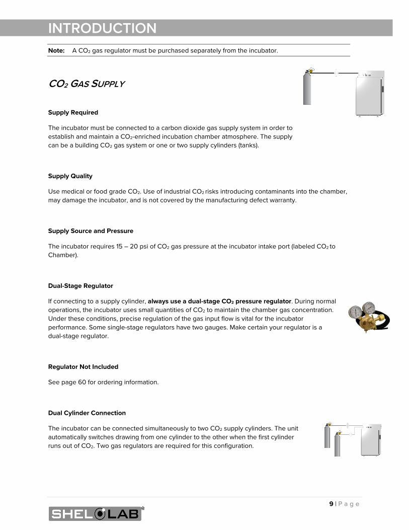
INTRODUCTION Note: A CO2 gas regulator must be purchased separately from the incubator.
CO2 GAS SUPPLY
Supply Required
The incubator must be connected to a carbon dioxide gas supply system in order to establish and maintain a CO2-enriched incubation chamber atmosphere. The supply can be a building CO2 gas system or one or two supply cylinders (tanks).
Supply Quality
Use medical or food grade CO2. Use of industrial CO2 risks introducing contaminants into the chamber, may damage the incubator, and is not covered by the manufacturing defect warranty.
Supply Source and Pressure
The incubator requires 15 – 20 psi of CO2 gas pressure at the incubator intake port (labeled CO2 to Chamber).
Dual-Stage Regulator
If connecting to a supply cylinder, always use a dual-stage CO2 pressure regulator. During normal operations, the incubator uses small quantities of CO2 to maintain the chamber gas concentration. Under these conditions, precise regulation of the gas input flow is vital for the incubator performance. Some single-stage regulators have two gauges. Make certain your regulator is a dual-stage regulator.
Regulator Not Included
See page 60 for ordering information.
Dual Cylinder Connection
The incubator can be connected simultaneously to two CO2 supply cylinders. The unit automatically switches drawing from one cylinder to the other when the first cylinder runs out of CO2. Two gas regulators are required for this configuration.
10 | P a g e
INTRODUCTION
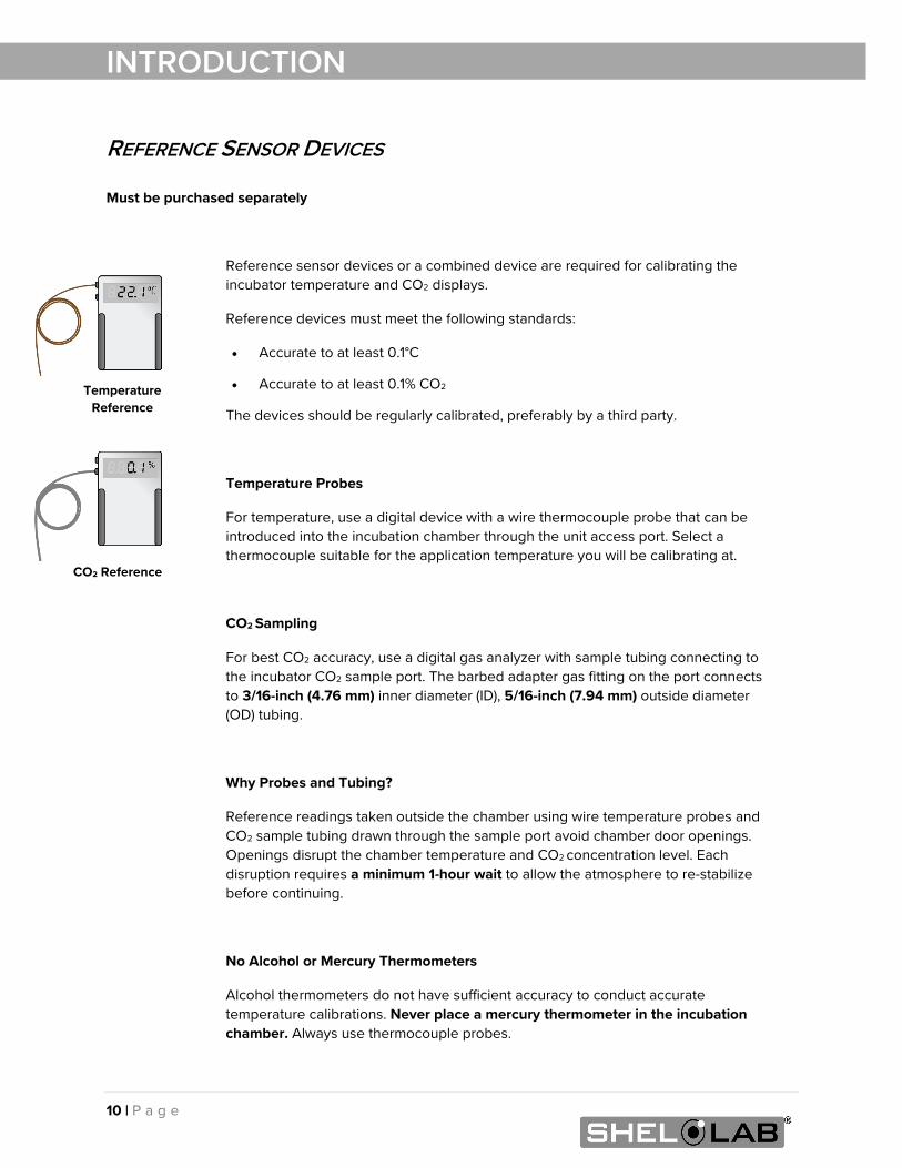
REFERENCE SENSOR DEVICES Must be purchased separately
Reference sensor devices or a combined device are required for calibrating the incubator temperature and CO2 displays.
Reference devices must meet the following standards:
• Accurate to at least 0.1°C
• Accurate to at least 0.1% CO2
The devices should be regularly calibrated, preferably by a third party.
Temperature Probes
For temperature, use a digital device with a wire thermocouple probe that can be introduced into the incubation chamber through the unit access port. Select a thermocouple suitable for the application temperature you will be calibrating at.
CO2 Sampling
For best CO2 accuracy, use a digital gas analyzer with sample tubing connecting to the incubator CO2 sample port. The barbed adapter gas fitting on the port connects to 3/16-inch (4.76 mm) inner diameter (ID), 5/16-inch (7.94 mm) outside diameter (OD) tubing.
Why Probes and Tubing?
Reference readings taken outside the chamber using wire temperature probes and CO2 sample tubing drawn through the sample port avoid chamber door openings. Openings disrupt the chamber temperature and CO2 concentration level. Each disruption requires a minimum 1-hour wait to allow the atmosphere to re-stabilize before continuing.
No Alcohol or Mercury Thermometers
Alcohol thermometers do not have sufficient accuracy to conduct accurate temperature calibrations. Never place a mercury thermometer in the incubation chamber. Always use thermocouple probes.
CO2 Reference
Temperature Reference
11 | P a g e
RECEIVING YOUR UNIT
INSPECT THE SHIPMENT • When a unit leaves the factory, safe delivery becomes the responsibility of the carrier.
• Damage sustained during transit is not covered by the manufacturing defect warranty.
• Save the shipping carton until you are certain that the unit and its accessories function properly.
When you receive your unit, inspect it for concealed loss or damage to its interior and exterior. If you find any damage to the unit, follow the carrier’s procedure for claiming damage or loss.
1. Carefully inspect the shipping carton for damage.
2. Report any damage to the carrier service that delivered the unit.
3. If the carton is not damaged, open the carton and remove the contents.
4. Inspect the unit for signs of damage. See the orientation depiction on the next page as a reference.
5. The unit should come with an Installation and Operation Manual.
6. Verify that the correct number of accessory items has been included.
7. Carefully check all packaging for accessory items before discarding.
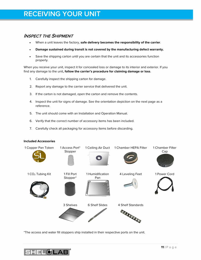
Included Accessories
1 Copper Pan Token
1 Access Port* Stopper
1 Ceiling Air Duct
1 Chamber HEPA Filter
1 Chamber Filter Cap
1 CO2 Tubing Kit
1 Fill Port Stopper*
1 Humidification Pan
4 Leveling Feet
1 Power Cord
3 Shelves
6 Shelf Slides
4 Shelf Standards
*The access and water fill stoppers ship installed in their respective ports on the unit.
12 | P a g e
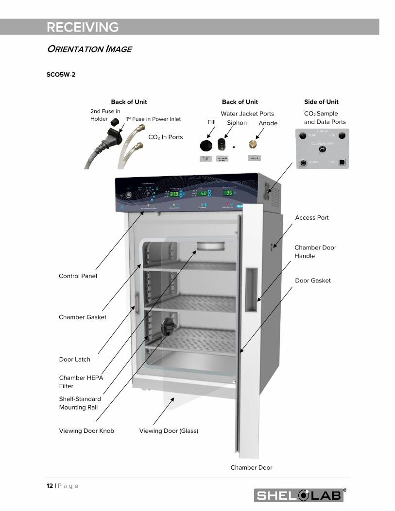
RECEIVING ORIENTATION IMAGE
1st Fuse in Power Inlet 2nd Fuse in Holder
SCO5W-2
Chamber Gasket
Chamber HEPA Filter
Door Latch
Viewing Door (Glass)
Chamber Door
Back of Unit
CO2 In Ports
Chamber Door Handle
Back of Unit
Fill Water Jacket Ports
Siphon
Viewing Door Knob
Anode
Access Port
Door Gasket
CO2 Sample and Data Ports
Control Panel
Side of Unit
Shelf-Standard Mounting Rail
13 | P a g e
RECEIVING
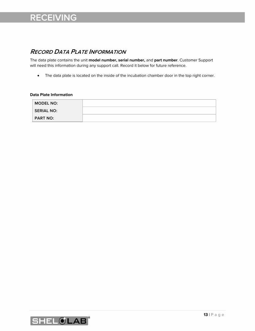
RECORD DATA PLATE INFORMATION The data plate contains the unit model number, serial number, and part number. Customer Support will need this information during any support call. Record it below for future reference.
• The data plate is located on the inside of the incubation chamber door in the top right corner.
Data Plate Information
MODEL NO:
SERIAL NO:
PART NO:

14 | P a g e
RECEIVING
15 | P a g e
INSTALLATION
INSTALLATION PROCEDURE CHECKLIST For installing the unit in a new workspace location.
Pre-Installation
Verify a CO2 gas supply source suitable for your application is available and can be connected to the incubator, page 9.
Check that the required ambient conditions for the unit are met, page 16.
Check that the spacing clearance requirements are met, page 16.
• Unit dimensions may be found on page 57.
Check that a suitable electrical outlet and power supply is present, page 17.
Install the incubator in a suitable location
Review the lifting and handling instructions, page 18.
Install the unit leveling feet, page 18.
Install the incubator in its workspace location, page 19.
Set up the incubator for use
Clean and disinfect the unit and accessories (except the HEPA filter), page 19.
Install the chamber HEPA filter and ceiling air duct in the incubation chamber, page 20.
Install the shelving, page 21.
Connect the incubator to the CO2 gas supply source, page 22.
Verify that the silicone stopper is installed in the access port inside the incubation chamber, page 23.
Fill the water jacket with 19 gallons (72 liters) of water, page 23.
16 | P a g e
INSTALLATION
REQUIRED AMBIENT CONDITIONS These units are built for use indoors at room temperatures between 15°C and 30°C (59°F and 86°F), at no greater than 80% Relative Humidity (at 25°C / 77°F The ambient temperature should not change by 2°C (3.6°F) or more during operation.
Operating outside these conditions may affect the incubator temperature performance.
When selecting a location to install the unit, consider all environmental conditions that can adversely impact its temperature performance. These include:
• Proximity to ovens, autoclaves, and any device that produces significant radiant heat
• Heating and cooling vents or other sources of fast-moving air currents
• High-traffic areas
• Direct sunlight
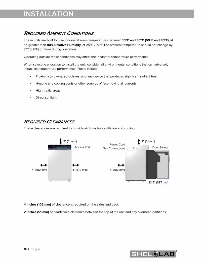
REQUIRED CLEARANCES These clearances are required to provide air flows for ventilation and cooling.
4 inches (102 mm) of clearance is required on the sides and back.
2 inches (51 mm) of headspace clearance between the top of the unit and any overhead partitions.
2” (51 mm)
4” (102 mm) 4” (102 mm)
Access Port
2” (51 mm)
4” (102 mm)
Door Swing
23.5” (597 mm)
Power Cord Gas Connections
17 | P a g e
INSTALLATION
POWER SOURCE REQUIREMENTS When selecting a location for the unit, verify each of the following requirements is satisfied.
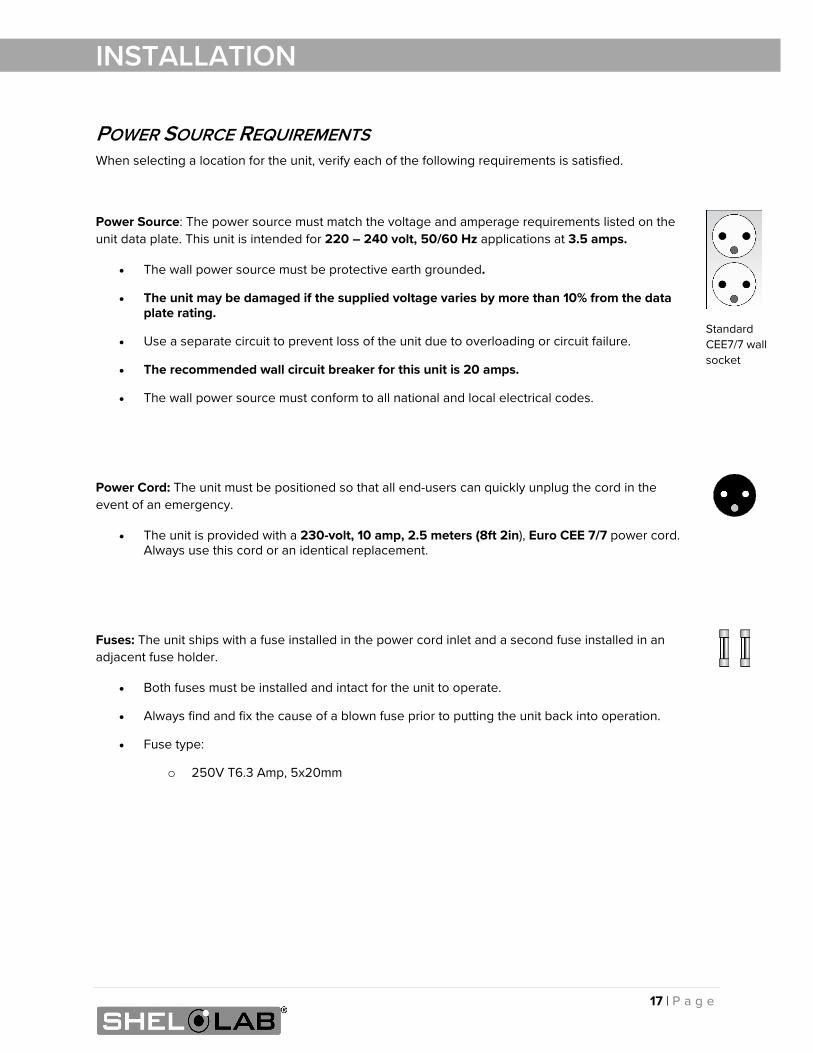
Power Source: The power source must match the voltage and amperage requirements listed on the unit data plate. This unit is intended for 220 – 240 volt, 50/60 Hz applications at 3.5 amps.
• The wall power source must be protective earth grounded.
• The unit may be damaged if the supplied voltage varies by more than 10% from the data plate rating.
• Use a separate circuit to prevent loss of the unit due to overloading or circuit failure.
• The recommended wall circuit breaker for this unit is 20 amps.
• The wall power source must conform to all national and local electrical codes.
Power Cord: The unit must be positioned so that all end-users can quickly unplug the cord in the event of an emergency.
• The unit is provided with a 230-volt, 10 amp, 2.5 meters (8ft 2in), Euro CEE 7/7 power cord. Always use this cord or an identical replacement.
Fuses: The unit ships with a fuse installed in the power cord inlet and a second fuse installed in an adjacent fuse holder.
• Both fuses must be installed and intact for the unit to operate.
• Always find and fix the cause of a blown fuse prior to putting the unit back into operation.
• Fuse type:
o 250V T6.3 Amp, 5x20mm
Standard CEE7/7 wall socket
18 | P a g e
INSTALLATION
LIFTING AND HANDLING The unit is heavy. Use appropriate lifting devices that are sufficiently rated for these loads. Follow these guidelines when lifting the unit.
• Lift the unit only from its bottom surface.
• Doors, handles, and knobs are not adequate for lifting or stabilization.
• Restrain the unit completely while lifting or transporting so it cannot tip.
• Remove all moving parts, such as shelves and trays, and lock doors in the closed position during transfers to prevent shifting and damage.
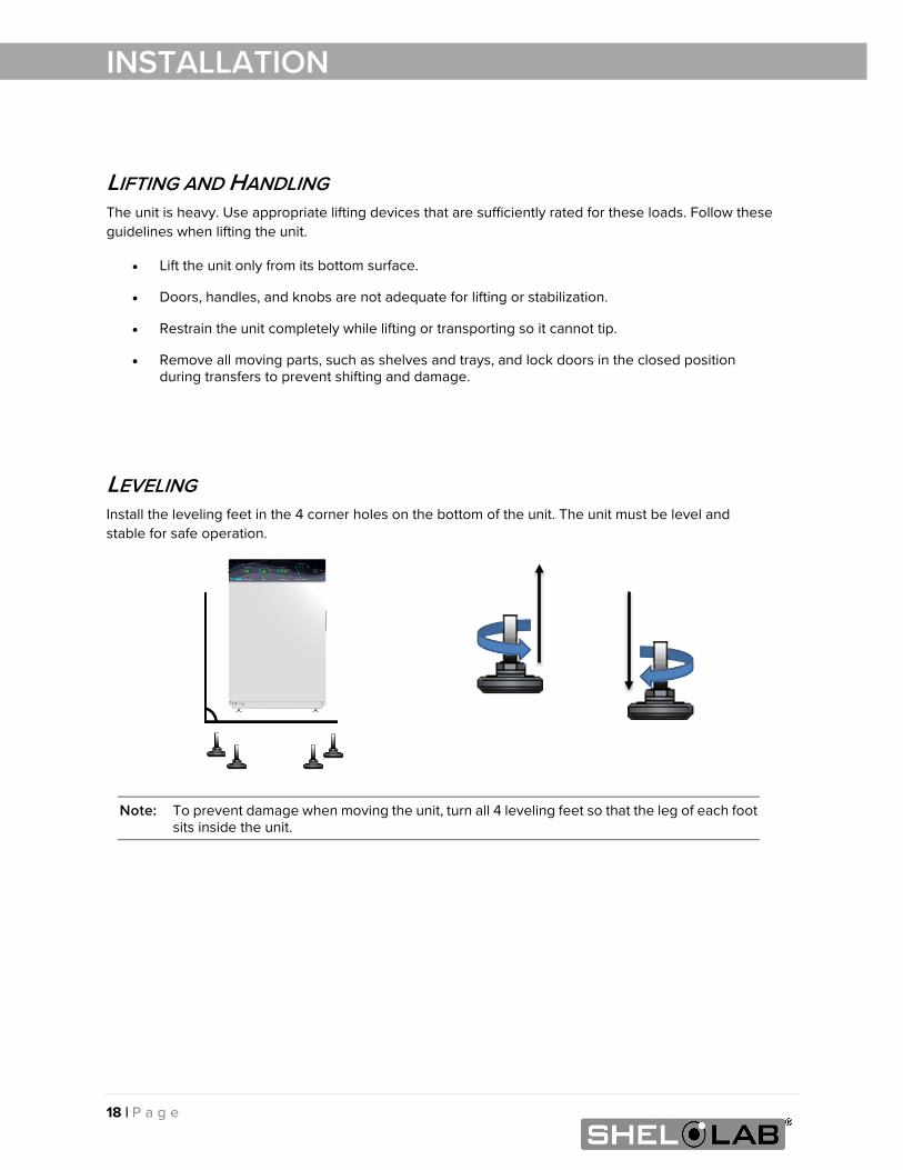
LEVELING Install the leveling feet in the 4 corner holes on the bottom of the unit. The unit must be level and stable for safe operation.
Note: To prevent damage when moving the unit, turn all 4 leveling feet so that the leg of each foot sits inside the unit.
19 | P a g e
INSTALLATION
INSTALL THE INCUBATOR Install the unit in a workspace location that meets the criteria discussed in the previous entries of the Installation section.
DEIONIZED AND DISTILLED WATER Do not use deionized water to clean the unit, even if DI water is readily available in your laboratory.
• Use of deionized water may corrode metal surfaces and is not covered by the manufacturing defect warranty.
• The manufacturer recommends the use of distilled water in the resistance range of 50K Ohm/cm to 1M Ohm/cm, or a conductivity range of 20.0 uS/cm to 1.0 uS/cm, for cleaning applications.
INSTALLATION - CLEAN AND DISINFECT The manufacturer recommends cleaning the shelving, ceiling air duct, and chamber prior to installation of the shelving and ceiling duct in the chamber.
• The unit was cleaned at the factory but may have been exposed to contaminants during shipping.
• Remove all wrappings and coverings from shelving and the ceiling air duct prior to cleaning and installation. Do not clean the shelving with deionized water.
• Do not clean the chamber HEPA filter.
• Please see the Cleaning and Disinfecting procedure on page 43 in the User Maintenance chapter for information on how to clean and disinfect without damaging the unit.
20 | P a g e
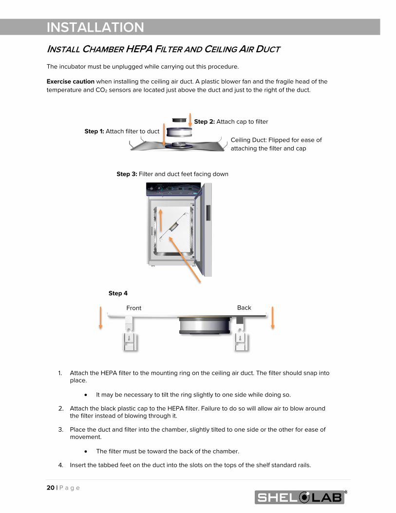
INSTALLATION INSTALL CHAMBER HEPA FILTER AND CEILING AIR DUCT The incubator must be unplugged while carrying out this procedure.
Exercise caution when installing the ceiling air duct. A plastic blower fan and the fragile head of the temperature and CO2 sensors are located just above the duct and just to the right of the duct.
Attach the HEPA filter to the mounting ring on the ceiling air duct. The filter should snap into place.
• It may be necessary to tilt the ring slightly to one side while doing so.
Attach the black plastic cap to the HEPA filter. Failure to do so will allow air to blow around the filter instead of blowing through it.
Place the duct and filter into the chamber, slightly tilted to one side or the other for ease of movement.
• The filter must be toward the back of the chamber.
Insert the tabbed feet on the duct into the slots on the tops of the shelf standard rails.
Step 4
Step 3: Filter and duct feet facing down
Step 2: Attach cap to filter
Step 1: Attach filter to duct
Back Front
Ceiling Duct: Flipped for ease of attaching the filter and cap
21 | P a g e
INSTALLATION
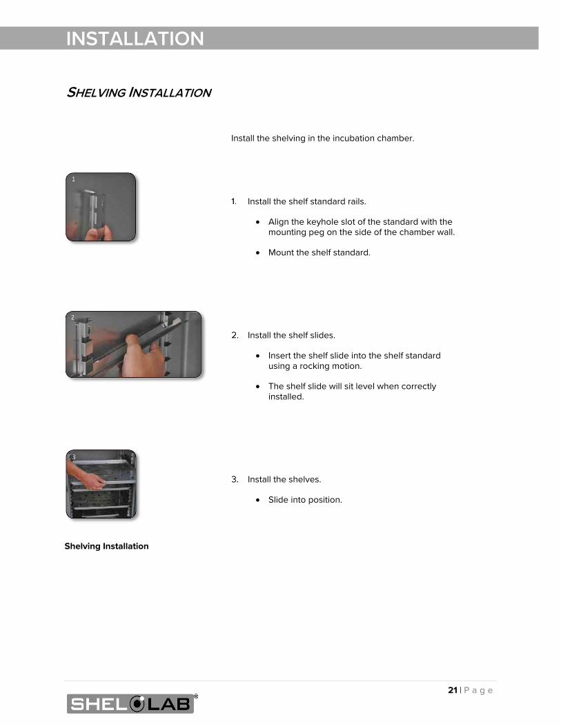
SHELVING INSTALLATION
Install the shelving in the incubation chamber.
Install the shelf standard rails.
• Align the keyhole slot of the standard with the mounting peg on the side of the chamber wall.
• Mount the shelf standard.
Install the shelf slides.
• Insert the shelf slide into the shelf standard using a rocking motion.
• The shelf slide will sit level when correctly installed.
Install the shelves.
• Slide into position.
Shelving Installation
22 | P a g e
INSTALLATION
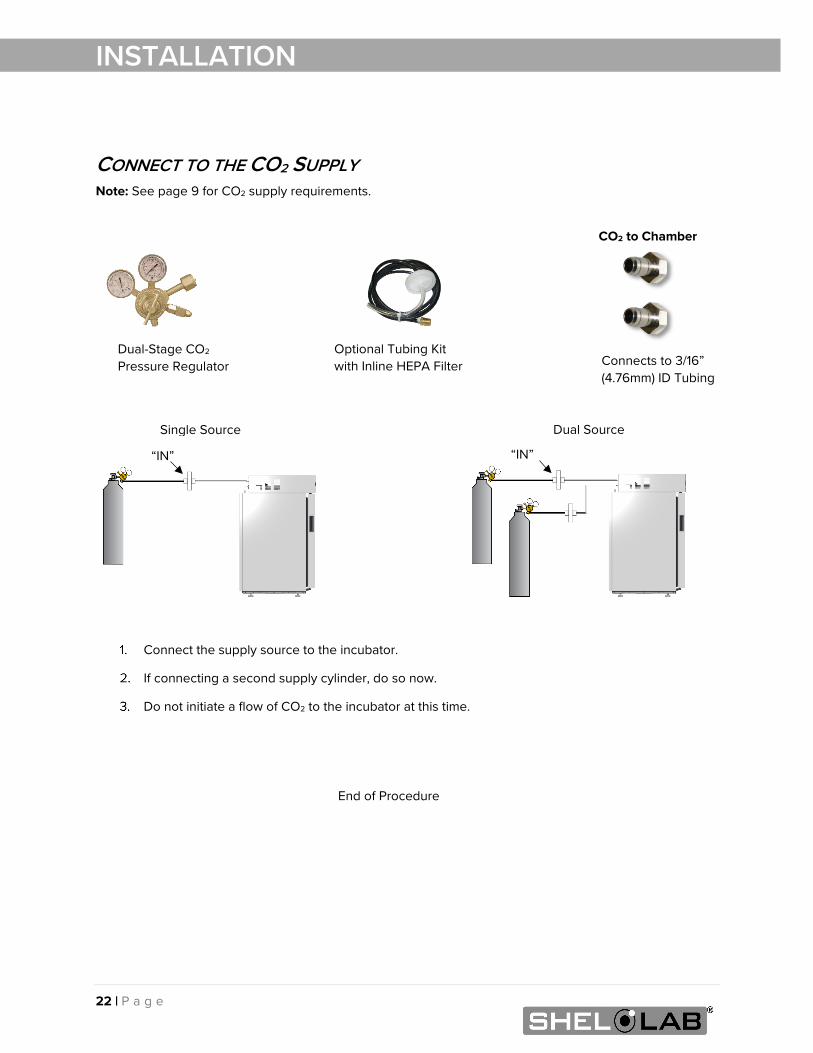
CONNECT TO THE CO2 SUPPLY Note: See page 9 for CO2 supply requirements.
Connect the supply source to the incubator.
If connecting a second supply cylinder, do so now.
Do not initiate a flow of CO2 to the incubator at this time.
End of Procedure
CO2 to Chamber
“IN”
Connects to 3/16” (4.76mm) ID Tubing
Single Source Dual Source
“IN”
Optional Tubing Kit with Inline HEPA Filter
Dual-Stage CO2 Pressure Regulator
23 | P a g e
INSTALLATION
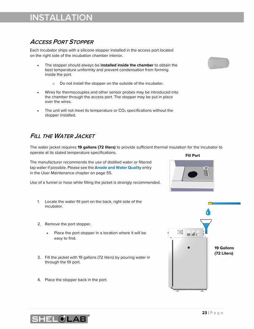
ACCESS PORT STOPPER Each incubator ships with a silicone stopper installed in the access port located on the right side of the incubation chamber interior.
• The stopper should always be installed inside the chamber to obtain the best temperature uniformity and prevent condensation from forming inside the port.
o Do not install the stopper on the outside of the incubator.
• Wires for thermocouples and other sensor probes may be introduced into the chamber through the access port. The stopper may be put in place over the wires.
• The unit will not meet its temperature or CO2 specifications without the stopper installed.
FILL THE WATER JACKET The water jacket requires 19 gallons (72 liters) to provide sufficient thermal insulation for the incubator to operate at its stated temperature specifications.
The manufacturer recommends the use of distilled water or filtered tap water if possible. Please see the Anode and Water Quality entry in the User Maintenance chapter on page 55.
Use of a funnel or hose while filling the jacket is strongly recommended.
Locate the water fill port on the back, right side of the incubator.
Remove the port stopper.
• Place the port stopper in a location where it will be easy to find.
Fill the jacket with 19 gallons (72 liters) by pouring water in through the fill port.
Place the stopper back in the port.
Fill Port
19 Gallons (72 Liters)
24 | P a g e
INSTALLATION
25 | P a g e
GRAPHIC SYMBOLS
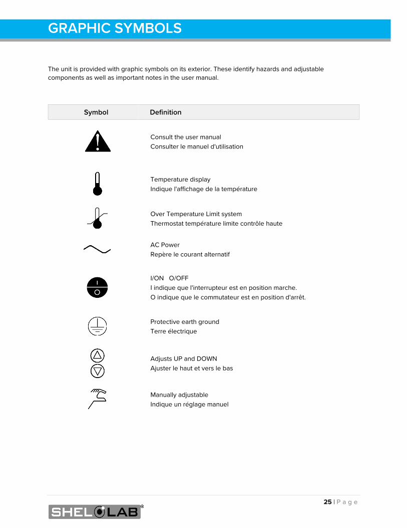
The unit is provided with graphic symbols on its exterior. These identify hazards and adjustable components as well as important notes in the user manual.
Symbol Definition
Consult the user manual Consulter le manuel d'utilisation
Temperature display Indique l'affichage de la température
Over Temperature Limit system Thermostat température limite contrôle haute
AC Power Repère le courant alternatif
I/ON O/OFF I indique que l'interrupteur est en position marche. O indique que le commutateur est en position d'arrêt.
Protective earth ground Terre électrique
Adjusts UP and DOWN Ajuster le haut et vers le bas
Manually adjustable Indique un réglage manuel
26 | P a g e
SYMBOLS
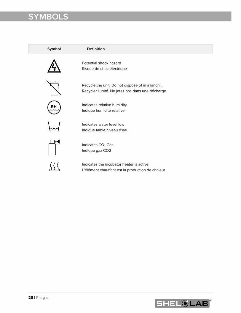
Symbol Definition
Potential shock hazard Risque de choc électrique
Recycle the unit. Do not dispose of in a landfill. Recycler l'unité. Ne jetez pas dans une décharge.
Indicates relative humidity Indique humidité relative
Indicates water level low Indique faible niveau d'eau
Indicates CO2 Gas Indique gaz CO2
Indicates the incubator heater is active L'élément chauffant est la production de chaleur
27 | P a g e
CONTROL PANEL OVERVIEW
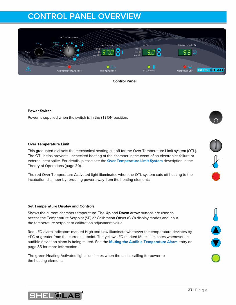
Power Switch
Power is supplied when the switch is in the ( I ) on position.
Power Switch
Power is supplied when the switch is in the ( I ) ON position.
Over Temperature Limit
This graduated dial sets the mechanical heating cut off for the Over Temperature Limit system (OTL). The OTL helps prevents unchecked heating of the chamber in the event of an electronics failure or external heat spike. For details, please see the Over Temperature Limit System description in the Theory of Operations (page 30).
The red Over Temperature Activated light illuminates when the OTL system cuts off heating to the incubation chamber by rerouting power away from the heating elements.
Set Temperature Display and Controls
Shows the current chamber temperature. The Up and Down arrow buttons are used to access the Temperature Setpoint (SP) or Calibration Offset (C O) display modes and input the temperature setpoint or calibration adjustment value.
Red LED alarm indicators marked High and Low illuminate whenever the temperature deviates by ±1°C or greater from the current setpoint. The yellow LED marked Mute illuminates whenever an audible deviation alarm is being muted. See the Muting the Audible Temperature Alarm entry on page 35 for more information.
The green Heating Activated light illuminates when the unit is calling for power to the heating elements.
Control Panel
28 | P a g e
CONTROL PANEL OVERVIEW
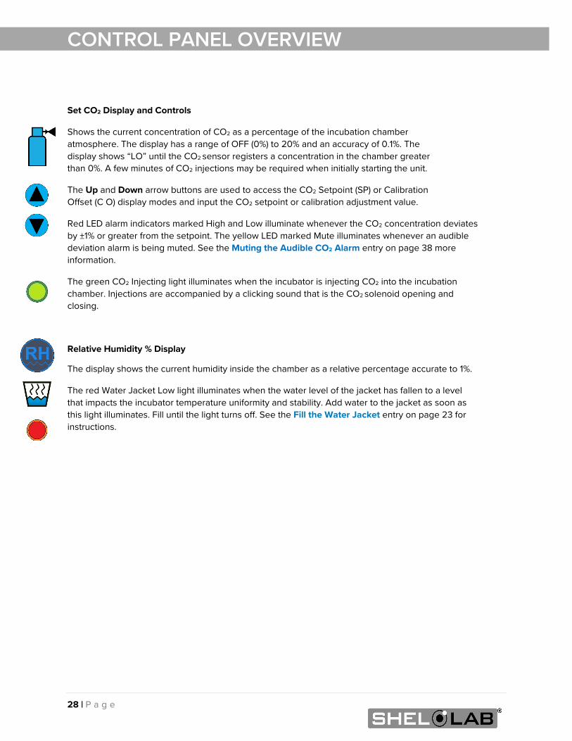
Set CO2 Display and Controls
Shows the current concentration of CO2 as a percentage of the incubation chamber atmosphere. The display has a range of OFF (0%) to 20% and an accuracy of 0.1%. The display shows “LO” until the CO2 sensor registers a concentration in the chamber greater than 0%. A few minutes of CO2 injections may be required when initially starting the unit.
The Up and Down arrow buttons are used to access the CO2 Setpoint (SP) or Calibration Offset (C O) display modes and input the CO2 setpoint or calibration adjustment value.
Red LED alarm indicators marked High and Low illuminate whenever the CO2 concentration deviates by ±1% or greater from the setpoint. The yellow LED marked Mute illuminates whenever an audible deviation alarm is being muted. See the Muting the Audible CO2 Alarm entry on page 38 more information.
The green CO2 Injecting light illuminates when the incubator is injecting CO2 into the incubation chamber. Injections are accompanied by a clicking sound that is the CO2 solenoid opening and closing.
Relative Humidity % Display
The display shows the current humidity inside the chamber as a relative percentage accurate to 1%.
The red Water Jacket Low light illuminates when the water level of the jacket has fallen to a level that impacts the incubator temperature uniformity and stability. Add water to the jacket as soon as this light illuminates. Fill until the light turns off. See the Fill the Water Jacket entry on page 23 for instructions.
29 | P a g e
OPERATION
THEORY OF OPERATION
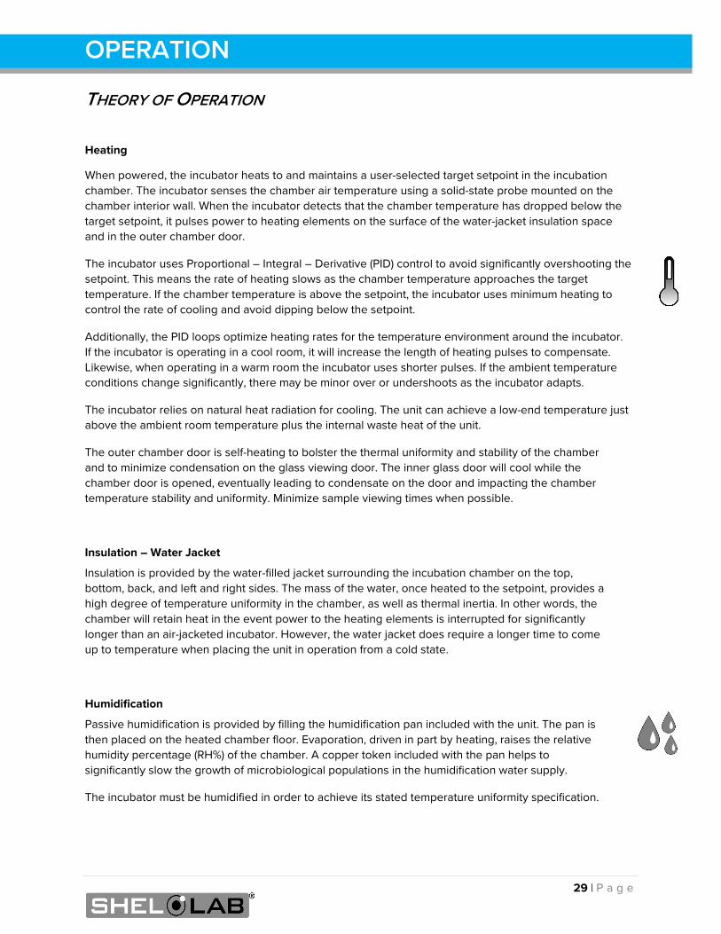
Heating
When powered, the incubator heats to and maintains a user-selected target setpoint in the incubation chamber. The incubator senses the chamber air temperature using a solid-state probe mounted on the chamber interior wall. When the incubator detects that the chamber temperature has dropped below the target setpoint, it pulses power to heating elements on the surface of the water-jacket insulation space and in the outer chamber door.
The incubator uses Proportional – Integral – Derivative (PID) control to avoid significantly overshooting the setpoint. This means the rate of heating slows as the chamber temperature approaches the target temperature. If the chamber temperature is above the setpoint, the incubator uses minimum heating to control the rate of cooling and avoid dipping below the setpoint.
Additionally, the PID loops optimize heating rates for the temperature environment around the incubator. If the incubator is operating in a cool room, it will increase the length of heating pulses to compensate. Likewise, when operating in a warm room the incubator uses shorter pulses. If the ambient temperature conditions change significantly, there may be minor over or undershoots as the incubator adapts.
The incubator relies on natural heat radiation for cooling. The unit can achieve a low-end temperature just above the ambient room temperature plus the internal waste heat of the unit.
The outer chamber door is self-heating to bolster the thermal uniformity and stability of the chamber and to minimize condensation on the glass viewing door. The inner glass door will cool while the chamber door is opened, eventually leading to condensate on the door and impacting the chamber temperature stability and uniformity. Minimize sample viewing times when possible.
Insulation – Water Jacket
Insulation is provided by the water-filled jacket surrounding the incubation chamber on the top, bottom, back, and left and right sides. The mass of the water, once heated to the setpoint, provides a high degree of temperature uniformity in the chamber, as well as thermal inertia. In other words, the chamber will retain heat in the event power to the heating elements is interrupted for significantly longer than an air-jacketed incubator. However, the water jacket does require a longer time to come up to temperature when placing the unit in operation from a cold state.
Humidification
Passive humidification is provided by filling the humidification pan included with the unit. The pan is then placed on the heated chamber floor. Evaporation, driven in part by heating, raises the relative humidity percentage (RH%) of the chamber. A copper token included with the pan helps to significantly slow the growth of microbiological populations in the humidification water supply.
The incubator must be humidified in order to achieve its stated temperature uniformity specification.
30 | P a g e
OPERATION
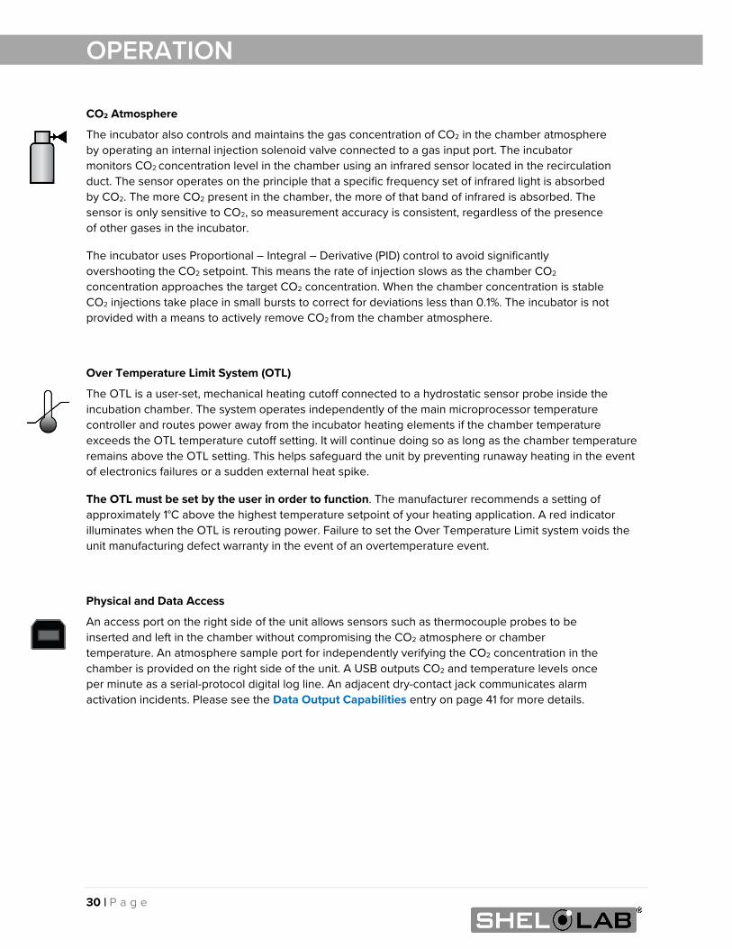
CO2 Atmosphere
The incubator also controls and maintains the gas concentration of CO2 in the chamber atmosphere by operating an internal injection solenoid valve connected to a gas input port. The incubator monitors CO2 concentration level in the chamber using an infrared sensor located in the recirculation duct. The sensor operates on the principle that a specific frequency set of infrared light is absorbed by CO2. The more CO2 present in the chamber, the more of that band of infrared is absorbed. The sensor is only sensitive to CO2, so measurement accuracy is consistent, regardless of the presence of other gases in the incubator.
The incubator uses Proportional – Integral – Derivative (PID) control to avoid significantly overshooting the CO2 setpoint. This means the rate of injection slows as the chamber CO2 concentration approaches the target CO2 concentration. When the chamber concentration is stable CO2 injections take place in small bursts to correct for deviations less than 0.1%. The incubator is not provided with a means to actively remove CO2 from the chamber atmosphere.
Over Temperature Limit System (OTL)
The OTL is a user-set, mechanical heating cutoff connected to a hydrostatic sensor probe inside the incubation chamber. The system operates independently of the main microprocessor temperature controller and routes power away from the incubator heating elements if the chamber temperature exceeds the OTL temperature cutoff setting. It will continue doing so as long as the chamber temperature remains above the OTL setting. This helps safeguard the unit by preventing runaway heating in the event of electronics failures or a sudden external heat spike.
The OTL must be set by the user in order to function. The manufacturer recommends a setting of approximately 1°C above the highest temperature setpoint of your heating application. A red indicator illuminates when the OTL is rerouting power. Failure to set the Over Temperature Limit system voids the unit manufacturing defect warranty in the event of an overtemperature event.
Physical and Data Access
An access port on the right side of the unit allows sensors such as thermocouple probes to be inserted and left in the chamber without compromising the CO2 atmosphere or chamber temperature. An atmosphere sample port for independently verifying the CO2 concentration in the chamber is provided on the right side of the unit. A USB outputs CO2 and temperature levels once per minute as a serial-protocol digital log line. An adjacent dry-contact jack communicates alarm activation incidents. Please see the Data Output Capabilities entry on page 41 for more details.
31 | P a g e
OPERATION Note: From a cold start, the incubator requires 12 hours to come up to and stabilize at temperature
and humidity levels prior to loading samples. Stabilization safeguards samples.
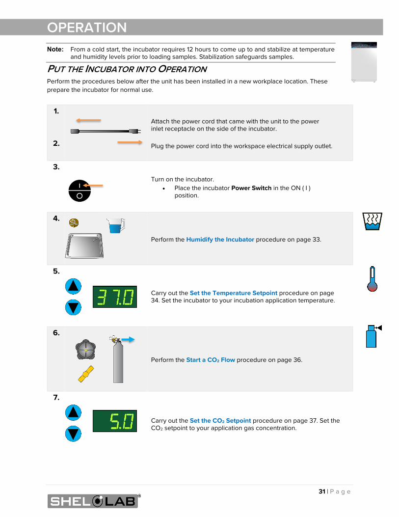
PUT THE INCUBATOR INTO OPERATION Perform the procedures below after the unit has been installed in a new workplace location. These prepare the incubator for normal use.
1.
2.
Attach the power cord that came with the unit to the power inlet receptacle on the side of the incubator. Plug the power cord into the workspace electrical supply outlet.
3.
Turn on the incubator. • Place the incubator Power Switch in the ON ( I )
position.
4.
Perform the Humidify the Incubator procedure on page 33.
5.
Carry out the Set the Temperature Setpoint procedure on page 34. Set the incubator to your incubation application temperature.
6.
Perform the Start a CO2 Flow procedure on page 36.
7.
Carry out the Set the CO2 Setpoint procedure on page 37. Set the CO2 setpoint to your application gas concentration.
32 | P a g e
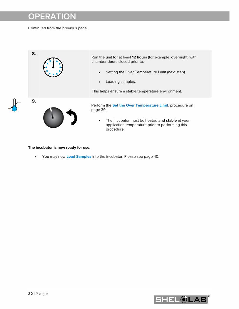
OPERATION Continued from the previous page.
The incubator is now ready for use.
• You may now Load Samples into the incubator. Please see page 40.
8. Run the unit for at least 12 hours (for example, overnight) with chamber doors closed prior to:
• Setting the Over Temperature Limit (next step).
• Loading samples.
This helps ensure a stable temperature environment.
9. Perform the Set the Over Temperature Limit. procedure on page 39.
• The incubator must be heated and stable at your application temperature prior to performing this procedure.
33 | P a g e
OPERATION
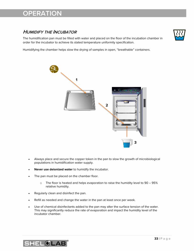
HUMIDIFY THE INCUBATOR The humidification pan must be filled with water and placed on the floor of the incubation chamber in order for the incubator to achieve its stated temperature uniformity specification.
Humidifying the chamber helps slow the drying of samples in open, “breathable” containers.
• Always place and secure the copper token in the pan to slow the growth of microbiological populations in humidification water supply.
• Never use deionized water to humidify the incubator.
• The pan must be placed on the chamber floor.
o The floor is heated and helps evaporation to raise the humidity level to 90 – 95% relative humidity.
• Regularly clean and disinfect the pan.
• Refill as needed and change the water in the pan at least once per week.
• Use of chemical disinfectants added to the pan may alter the surface tension of the water. This may significantly reduce the rate of evaporation and impact the humidity level of the incubator chamber.
1
2
3
34 | P a g e
OPERATION
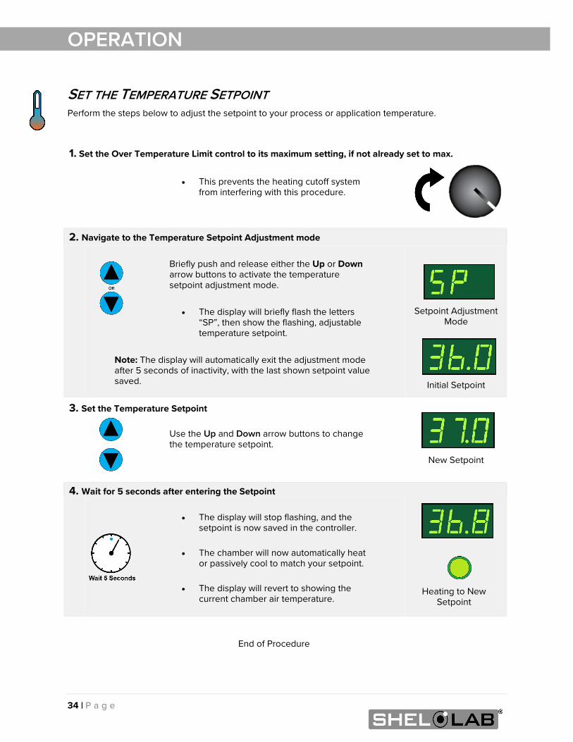
SET THE TEMPERATURE SETPOINT Perform the steps below to adjust the setpoint to your process or application temperature.
End of Procedure
1. Set the Over Temperature Limit control to its maximum setting, if not already set to max.
• This prevents the heating cutoff system from interfering with this procedure.
2. Navigate to the Temperature Setpoint Adjustment mode
Briefly push and release either the Up or Down arrow buttons to activate the temperature setpoint adjustment mode.
• The display will briefly flash the letters
“SP”, then show the flashing, adjustable temperature setpoint.
Note: The display will automatically exit the adjustment mode after 5 seconds of inactivity, with the last shown setpoint value saved.
Setpoint Adjustment Mode
Initial Setpoint
3. Set the Temperature Setpoint
Use the Up and Down arrow buttons to change the temperature setpoint.
New Setpoint
4. Wait for 5 seconds after entering the Setpoint
• The display will stop flashing, and the setpoint is now saved in the controller.
• The chamber will now automatically heat
or passively cool to match your setpoint.
• The display will revert to showing the current chamber air temperature.
Heating to New Setpoint
35 | P a g e
OPERATION
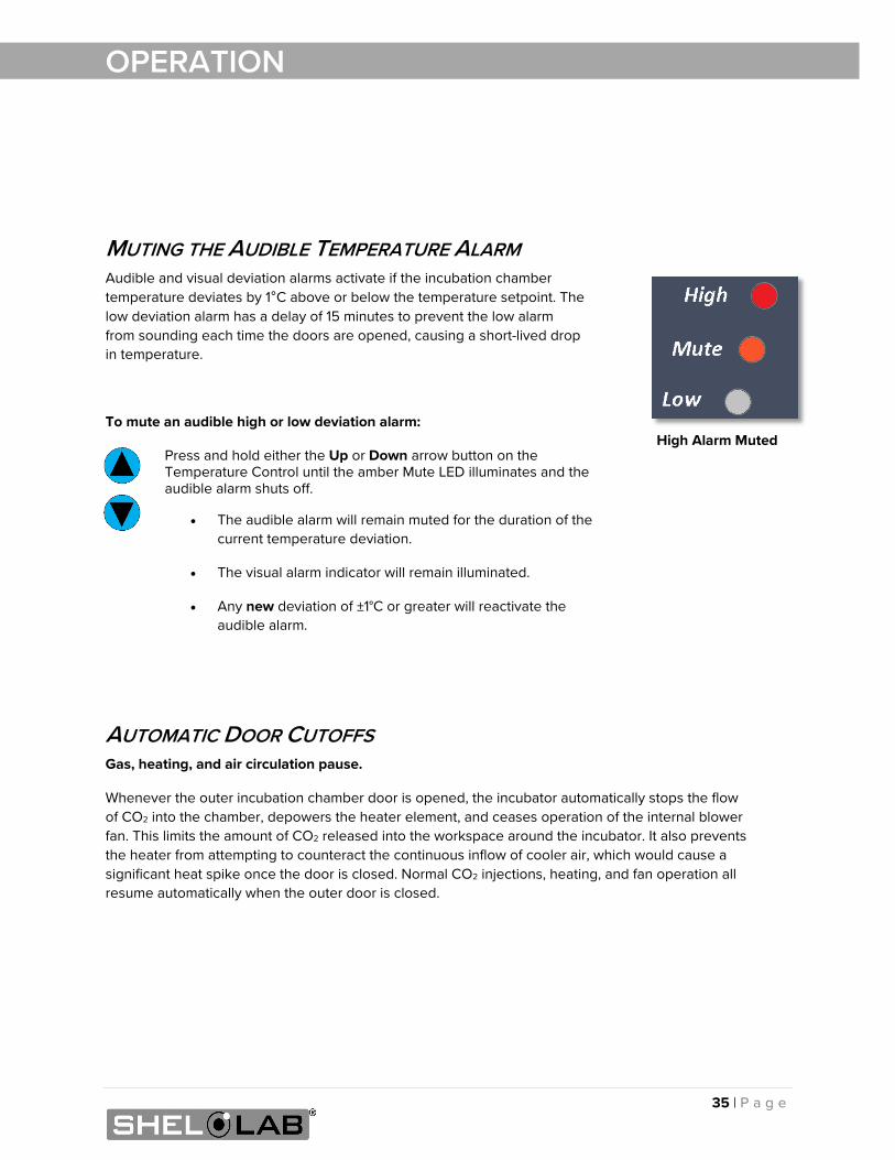
MUTING THE AUDIBLE TEMPERATURE ALARM Audible and visual deviation alarms activate if the incubation chamber temperature deviates by 1°C above or below the temperature setpoint. The low deviation alarm has a delay of 15 minutes to prevent the low alarm from sounding each time the doors are opened, causing a short-lived drop in temperature.
To mute an audible high or low deviation alarm:
Press and hold either the Up or Down arrow button on the Temperature Control until the amber Mute LED illuminates and the audible alarm shuts off.
• The audible alarm will remain muted for the duration of the current temperature deviation.
• The visual alarm indicator will remain illuminated.
• Any new deviation of ±1°C or greater will reactivate the audible alarm.
AUTOMATIC DOOR CUTOFFS Gas, heating, and air circulation pause.
Whenever the outer incubation chamber door is opened, the incubator automatically stops the flow of CO2 into the chamber, depowers the heater element, and ceases operation of the internal blower fan. This limits the amount of CO2 released into the workspace around the incubator. It also prevents the heater from attempting to counteract the continuous inflow of cooler air, which would cause a significant heat spike once the door is closed. Normal CO2 injections, heating, and fan operation all resume automatically when the outer door is closed.
High Alarm Muted
36 | P a g e
OPERATION
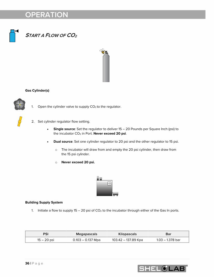
START A FLOW OF CO2
Gas Cylinder(s)
Open the cylinder valve to supply CO2 to the regulator.
Set cylinder regulator flow setting.
• Single source: Set the regulator to deliver 15 – 20 Pounds per Square Inch (psi) to the incubator CO2 in Port. Never exceed 20 psi.
• Dual source: Set one cylinder regulator to 20 psi and the other regulator to 15 psi.
o The incubator will draw from and empty the 20 psi cylinder, then draw from the 15 psi cylinder.
o Never exceed 20 psi.
Building Supply System
Initiate a flow to supply 15 – 20 psi of CO2 to the incubator through either of the Gas In ports.
PSI Megapascals Kilopascals Bar
15 – 20 psi 0.103 – 0.137 Mpa 103.42 – 137.89 Kpa 1.03 – 1.378 bar
37 | P a g e
OPERATION
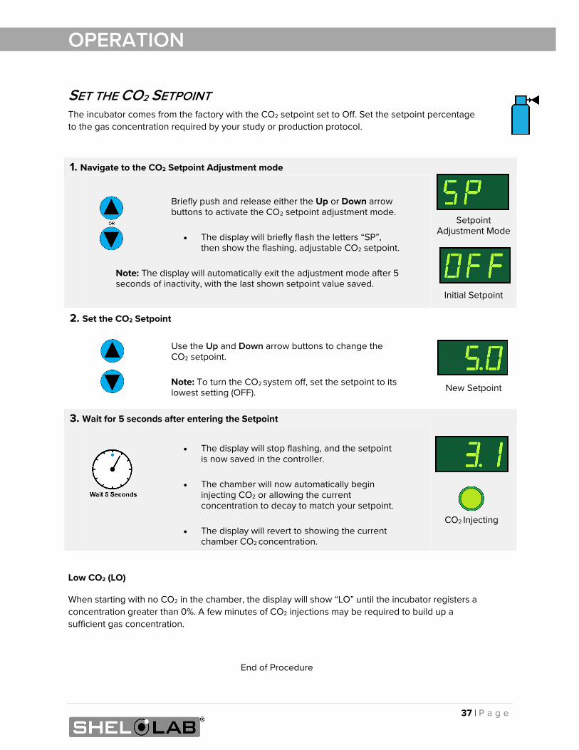
SET THE CO2 SETPOINT The incubator comes from the factory with the CO2 setpoint set to Off. Set the setpoint percentage to the gas concentration required by your study or production protocol.
Low CO2 (LO)
When starting with no CO2 in the chamber, the display will show “LO” until the incubator registers a concentration greater than 0%. A few minutes of CO2 injections may be required to build up a sufficient gas concentration.
End of Procedure
1. Navigate to the CO2 Setpoint Adjustment mode
Briefly push and release either the Up or Down arrow buttons to activate the CO2 setpoint adjustment mode.
• The display will briefly flash the letters “SP”,
then show the flashing, adjustable CO2 setpoint.
Note: The display will automatically exit the adjustment mode after 5 seconds of inactivity, with the last shown setpoint value saved.
Setpoint Adjustment Mode
Initial Setpoint
2. Set the CO2 Setpoint
Use the Up and Down arrow buttons to change the CO2 setpoint. Note: To turn the CO2 system off, set the setpoint to its lowest setting (OFF).
New Setpoint
3. Wait for 5 seconds after entering the Setpoint
• The display will stop flashing, and the setpoint is now saved in the controller.
• The chamber will now automatically begin
injecting CO2 or allowing the current concentration to decay to match your setpoint.
• The display will revert to showing the current
chamber CO2 concentration.
CO2 Injecting
38 | P a g e
OPERATION
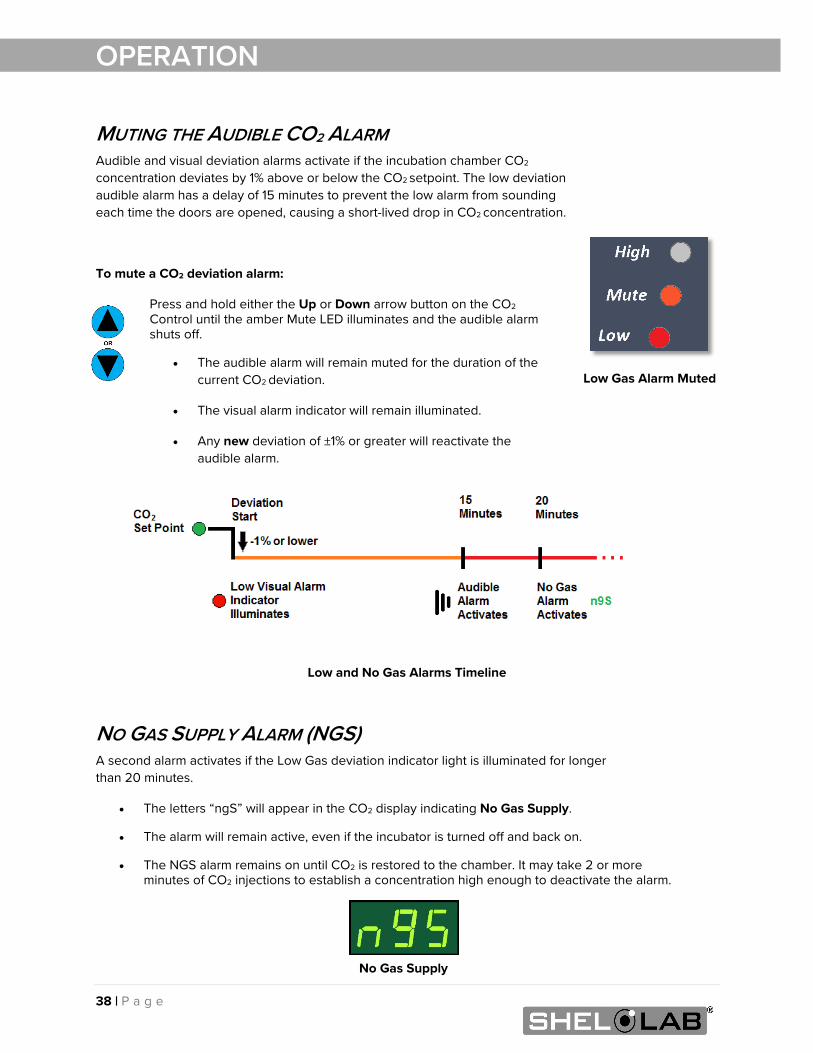
MUTING THE AUDIBLE CO2 ALARM Audible and visual deviation alarms activate if the incubation chamber CO2
concentration deviates by 1% above or below the CO2 setpoint. The low deviation audible alarm has a delay of 15 minutes to prevent the low alarm from sounding each time the doors are opened, causing a short-lived drop in CO2 concentration.
To mute a CO2 deviation alarm:
Press and hold either the Up or Down arrow button on the CO2 Control until the amber Mute LED illuminates and the audible alarm shuts off.
• The audible alarm will remain muted for the duration of the current CO2 deviation.
• The visual alarm indicator will remain illuminated.
• Any new deviation of ±1% or greater will reactivate the audible alarm.
Low and No Gas Alarms Timeline
NO GAS SUPPLY ALARM (NGS) A second alarm activates if the Low Gas deviation indicator light is illuminated for longer than 20 minutes.
• The letters “ngS” will appear in the CO2 display indicating No Gas Supply.
• The alarm will remain active, even if the incubator is turned off and back on.
• The NGS alarm remains on until CO2 is restored to the chamber. It may take 2 or more minutes of CO2 injections to establish a concentration high enough to deactivate the alarm.
Low Gas Alarm Muted
No Gas Supply
39 | P a g e
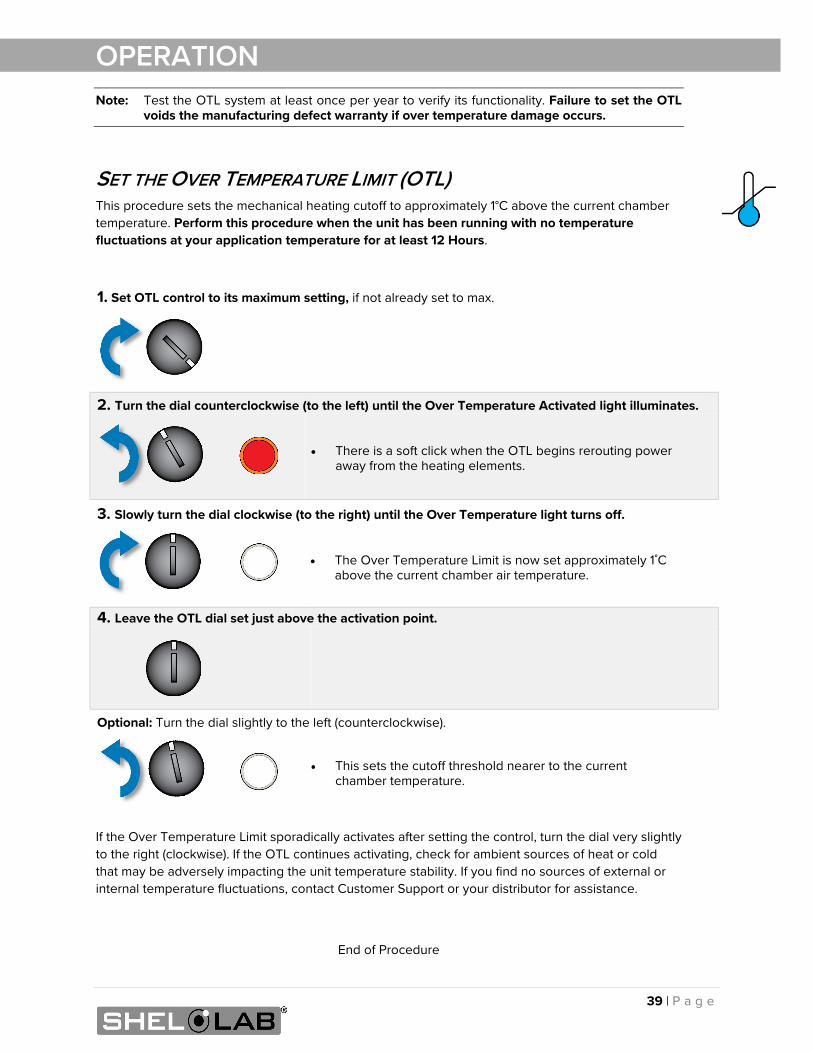
OPERATION Note: Test the OTL system at least once per year to verify its functionality. Failure to set the OTL
voids the manufacturing defect warranty if over temperature damage occurs.
SET THE OVER TEMPERATURE LIMIT (OTL) This procedure sets the mechanical heating cutoff to approximately 1°C above the current chamber temperature. Perform this procedure when the unit has been running with no temperature fluctuations at your application temperature for at least 12 Hours.
If the Over Temperature Limit sporadically activates after setting the control, turn the dial very slightly to the right (clockwise). If the OTL continues activating, check for ambient sources of heat or cold that may be adversely impacting the unit temperature stability. If you find no sources of external or internal temperature fluctuations, contact Customer Support or your distributor for assistance.
End of Procedure
1. Set OTL control to its maximum setting, if not already set to max.
2. Turn the dial counterclockwise (to the left) until the Over Temperature Activated light illuminates.
• There is a soft click when the OTL begins rerouting power away from the heating elements.
3. Slowly turn the dial clockwise (to the right) until the Over Temperature light turns off.
• The Over Temperature Limit is now set approximately 1˚C above the current chamber air temperature.
4. Leave the OTL dial set just above the activation point.
Optional: Turn the dial slightly to the left (counterclockwise).
• This sets the cutoff threshold nearer to the current chamber temperature.
40 | P a g e
OPERATION
LOADING SAMPLES The manufacturer strongly recommends waiting at least 12 hours after putting the incubator in operation before loading samples in the chamber. This safeguards against temperature instability.
• Samples should be placed at least 1 inch (25 mm) away from the chamber walls.
• Samples or sample stacks should be spaced 1 inch (25 mm) apart.
• Proper spacing allows for maximum air circulation and a higher degree of temperature uniformity.
• Proper spacing also decreases the chance of condensate forming in the incubator when operating with a large number of samples in the chamber.
ACCESSORY COMPATIBILITY • Verify that any powered accessory equipment used inside the chamber can safely and
effectively operate within your selected temperature, humidity, and CO2 concentration range.
• Powered equipment, such as stirrers or shakers, can generate heat sufficient to disrupt the thermal uniformity and stability of the chamber.
41 | P a g e
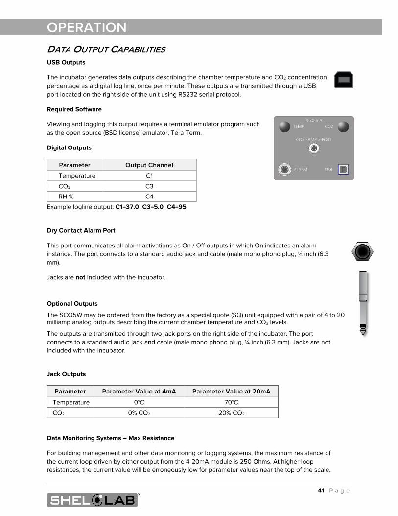
OPERATION DATA OUTPUT CAPABILITIES USB Outputs
The incubator generates data outputs describing the chamber temperature and CO2 concentration percentage as a digital log line, once per minute. These outputs are transmitted through a USB port located on the right side of the unit using RS232 serial protocol.
Required Software
Viewing and logging this output requires a terminal emulator program such as the open source (BSD license) emulator, Tera Term.
Digital Outputs
Parameter Output Channel
Temperature C1
CO2 C3
RH % C4
Example logline output: C1=37.0 C3=5.0 C4=95
Dry Contact Alarm Port
This port communicates all alarm activations as On / Off outputs in which On indicates an alarm instance. The port connects to a standard audio jack and cable (male mono phono plug, ¼ inch (6.3 mm).
Jacks are not included with the incubator.
Optional Outputs
The SCO5W may be ordered from the factory as a special quote (SQ) unit equipped with a pair of 4 to 20 milliamp analog outputs describing the current chamber temperature and CO2 levels.
The outputs are transmitted through two jack ports on the right side of the incubator. The port connects to a standard audio jack and cable (male mono phono plug, ¼ inch (6.3 mm). Jacks are not included with the incubator.
Jack Outputs
Parameter Parameter Value at 4mA Parameter Value at 20mA
Temperature 0°C 70°C
CO2 0% CO2 20% CO2
Data Monitoring Systems – Max Resistance
For building management and other data monitoring or logging systems, the maximum resistance of the current loop driven by either output from the 4-20mA module is 250 Ohms. At higher loop resistances, the current value will be erroneously low for parameter values near the top of the scale.
42 | P a g e
OPERATION
CONDENSATION AND THE DEW POINT Relative humidity inside the incubator chamber should never be allowed to exceed 95%. Exceeding this threshold will likely result in condensation in the chamber and subsequent leakage from the incubator. This may cause corrosion damage if allowed to continue for any significant length of time.
Condensation takes place whenever the humidity level in the incubator chamber reaches the dew point. The dew point is the level of humidity at which the air cannot hold more water vapor. The warmer the air, the more water vapor it can hold.
As the level of humidity rises in an incubation chamber, condensate will first appear on surfaces that are cooler than the air temperature. Near the dew point, condensate forms on any item or exposed surface even slightly cooler than the air. When the dew point is reached, condensate forms on nearly all exposed surfaces.
Managing condensation primarily depends on either lowering the humidity level or increasing the air temperature in the incubator chamber.
Note: Rising or falling air pressure from the weather will adjust the dew point up and down in small increments. If the relative humidity in the incubation chamber is already near the dew point, barometric fluctuations may push it across the dew point threshold.
Note: Thin air at higher altitudes holds less humidity than the denser air found at or near sea level.
If excessive condensate has appeared in the incubation chamber, dry the chamber interior and check the following.
• Verify that the access port stopper is in place on the inside of the incubation chamber and not on the unit exterior.
• Make sure samples on any shelving in the chamber are evenly spaced to allow for good airflow.
• Ensure the chamber door is closing and latching properly.
• Are frequent or lengthy chamber door openings causing significant temperature disruptions and chilling the chamber surfaces? If so, reduce the number of openings.
• Are there too many open or “breathable” containers of evaporating sample media in the chamber? If so, reduce the number of open sample containers.
• Does the ambient humidity in the room exceed the stated operating range of 80% relative environmental humidity? If so, lower the room humidity.
• Is the incubator exposed to an external flow of cold air such as an air-conditioning vent or a door to a cooler hallway or adjacent room? Block or divert the air, or reposition the unit.
• Check the door gaskets for damage, wear, or signs of brittleness or dryness. Arrange for replacement of the gaskets if damaged or excessively worn.
43 | P a g e
USER MAINTENANCE
Warning: Disconnect the unit from its power supply prior to performing maintenance or services.
Avertissement: Débranchez cet appareil de son alimentation électrique avant d'effectuer la maintenance ou les services.
CLEANING AND DISINFECTING If a hazardous material or substance has spilled in the unit chamber, immediately initiate your site Hazardous Material Spill Containment protocol. Contact your local Site Safety Officer and follow instructions per the site policy and procedures.
• Periodic cleaning and disinfection are required.
• Do not use spray-on cleaners or disinfectants. These can leak through openings and coat electrical components.
• Consult with the manufacturer or their agent if you have any doubts about the compatibility of decontamination or cleaning agents with the parts of the equipment or with the material contained in it.
• Do not use cleaners or disinfectants that contain solvents capable of harming paint coatings or stainless-steel surfaces. Do not use chlorine-based bleaches or abrasives; these will damage the chamber liner.
• Do not clean or disinfect the ring-style chamber HEPA filter. Replace the filter if discolored or if you believe it has been contaminated.
Warning: Exercise caution if cleaning the unit with alcohol or flammable cleaners. Always allow the unit to cool down to room temperature prior to cleaning and make sure all cleaning agents have evaporated or otherwise been completely removed prior to putting the unit back into service.
Avertissement: Soyez prudent lorsque vous nettoyez l'appareil avec de l'alcool ou des produits de nettoyage inflammables. Laissez toujours refroidir l'appareil à la température ambiante avant le nettoyage et assurez-vous que tous les produits de nettoyage se sont évaporés ou ont été complètement enlevés avant de remettre l'appareil en service.
Cleaning
Disconnect the unit from its power supply.
Remove all removable interior components such as shelving and accessories.
Clean the unit with a mild soap and water solution, including all corners.
o Do not use an abrasive cleaner, these will damage metal surfaces.
o Do not use deionized water to rinse or clean with.
o Take special care when cleaning around the temperature sensor probes in the chamber to prevent damage. Do not clean the probes.
Rinse with distilled water and wipe dry with a soft cloth.
44 | P a g e
MAINTENANCE
Disinfecting
For maximum effectiveness, disinfection procedures are typically performed after cleaning. Keep the following points in mind when disinfecting the unit.
• Turn off and disconnect the unit to safeguard against electrical hazards.
• Disinfect the unit chamber using commercially available disinfectants that are non-corrosive, non-abrasive, and suitable for use on stainless steel and glass surfaces. Contact your local Site Safety Officer for detailed information on which disinfectants are compatible with your applications.
• If permitted by your protocol, remove all removable interior accessories (shelving and other non-attached items) from the chamber when disinfecting.
• Disinfect all surfaces in the chamber, making sure to thoroughly disinfect the corners. Exercise care to avoid damaging the sensor probes.
• Gas concentrations from evaporating disinfecting agents can inhibit growth or cause metabolic symptoms in microbiological sample populations. Make sure that chlorines, quaternary ammonias, or any other overtly volatile disinfecting agents have been rinsed or otherwise removed from the chamber surfaces, prior to placing samples in the chamber.
When disinfecting external surfaces, use disinfectants that will not damage painted metal, glass, and plastic.
MINIMIZING CONTAMINATION EXPOSURE Suggestions for minimizing exposure of the incubator chamber to potential contaminants.
• Maintain a high air quality in the laboratory workspaces around the incubator.
• Avoid placing the incubator near sources of air movement such as doors, air vents, or high traffic routes in the workspace.
• Minimize the number of times the incubator chamber door is opened during normal operations.
MAINTAINING ATMOSPHERIC INTEGRITY Periodically, inspect the door latch, trim, catch, and gaskets for signs of deterioration. Failure to maintain the integrity of the door system shortens the lifespan of the incubator.
45 | P a g e
MAINTENANCE
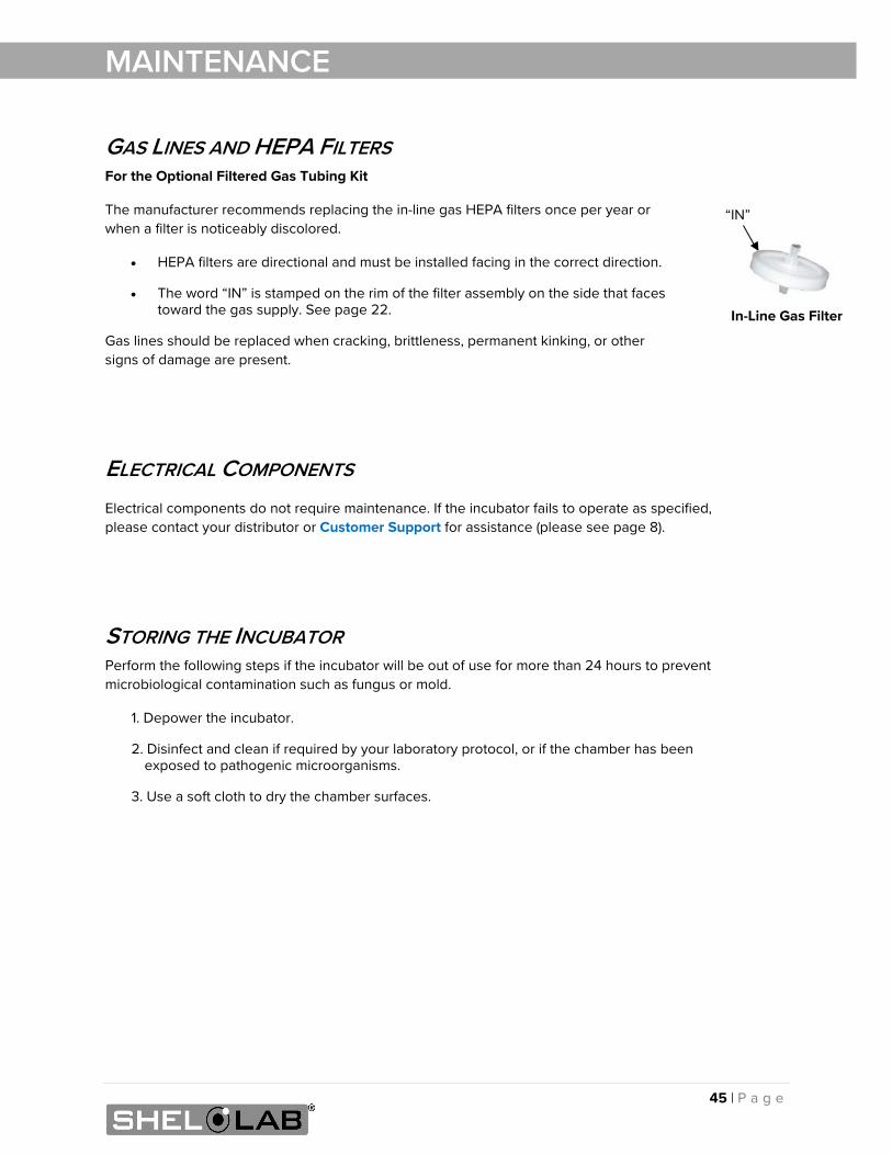
GAS LINES AND HEPA FILTERS For the Optional Filtered Gas Tubing Kit
The manufacturer recommends replacing the in-line gas HEPA filters once per year or when a filter is noticeably discolored.
• HEPA filters are directional and must be installed facing in the correct direction.
• The word “IN” is stamped on the rim of the filter assembly on the side that faces toward the gas supply. See page 22.
Gas lines should be replaced when cracking, brittleness, permanent kinking, or other signs of damage are present.
ELECTRICAL COMPONENTS Electrical components do not require maintenance. If the incubator fails to operate as specified, please contact your distributor or Customer Support for assistance (please see page 8).
STORING THE INCUBATOR Perform the following steps if the incubator will be out of use for more than 24 hours to prevent microbiological contamination such as fungus or mold.
1. Depower the incubator.
2. Disinfect and clean if required by your laboratory protocol, or if the chamber has been exposed to pathogenic microorganisms.
3. Use a soft cloth to dry the chamber surfaces.
“IN”
In-Line Gas Filter
46 | P a g e
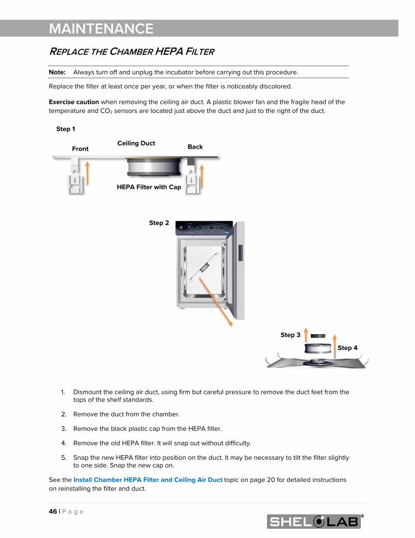
MAINTENANCE REPLACE THE CHAMBER HEPA FILTER
Note: Always turn off and unplug the incubator before carrying out this procedure.
Replace the filter at least once per year, or when the filter is noticeably discolored.
Exercise caution when removing the ceiling air duct. A plastic blower fan and the fragile head of the temperature and CO2 sensors are located just above the duct and just to the right of the duct.
Dismount the ceiling air duct, using firm but careful pressure to remove the duct feet from the tops of the shelf standards.
Remove the duct from the chamber.
Remove the black plastic cap from the HEPA filter.
Remove the old HEPA filter. It will snap out without difficulty.
Snap the new HEPA filter into position on the duct. It may be necessary to tilt the filter slightly to one side. Snap the new cap on.
See the Install Chamber HEPA Filter and Ceiling Air Duct topic on page 20 for detailed instructions on reinstalling the filter and duct.
Step 1
Step 2
Step 3
Step 4
Back Front Ceiling Duct
HEPA Filter with Cap
47 | P a g e
MAINTENANCE CALIBRATE THE TEMPERATURE DISPLAY Note: This procedure requires a temperature reference device. Please see the Reference Sensor Device entry on page 10 for the device requirements.
Temperature calibrations match the temperature display to the actual air temperature inside the incubation chamber. The actual air temperature is supplied by a reference sensor device. Calibrations compensate for software drifts in the controller as well as deviations caused by the natural material evolution of the sensor probe in the heated chamber space. Calibrate as often as required by your laboratory or production protocol, or regulatory compliance schedule. Always calibrate to the industry or regulatory standards required for your application.
Humidity
Humidity affects temperature uniformity and stability in the incubation chamber. The chamber must be humidified for at least 24 hours in order to conduct an accurate calibration.
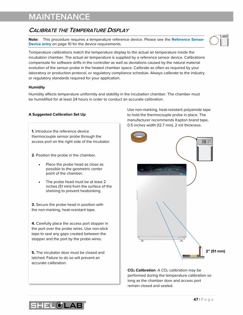
A Suggested Calibration Set Up
CO2 Calibration: A CO2 calibration may be performed during the temperature calibration so long as the chamber door and access port remain closed and sealed.
1. Introduce the reference device thermocouple sensor probe through the access port on the right side of the incubator.
2. Position the probe in the chamber.
• Place the probe head as close as possible to the geometric center point of the chamber.
• The probe head must be at least 2 inches (51 mm) from the surface of the shelving to prevent heatsinking.
3. Secure the probe head in position with the non-marking, heat-resistant tape.
4. Carefully place the access port stopper in the port over the probe wires. Use non-stick tape to seal any gaps created between the stopper and the port by the probe wires.
5. The incubator door must be closed and latched. Failure to do so will prevent an accurate calibration.
2” (51 mm)
Use non-marking, heat-resistant polyamide tape to hold the thermocouple probe in place. The manufacturer recommends Kapton brand tape, 0.5 inches width (12.7 mm), 2 mil thickness.
48 | P a g e
Begin Calibration
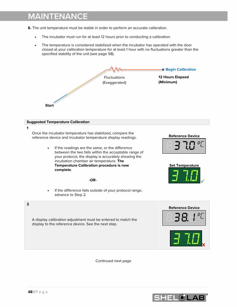
MAINTENANCE 6. The unit temperature must be stable in order to perform an accurate calibration.
• The incubator must run for at least 12 hours prior to conducting a calibration.
• The temperature is considered stabilized when the incubator has operated with the door closed at your calibration temperature for at least 1 hour with no fluctuations greater than the specified stability of the unit (see page 58).
Continued next page
Suggested Temperature Calibration 1
Once the incubator temperature has stabilized, compare the reference device and incubator temperature display readings.
• If the readings are the same, or the difference between the two falls within the acceptable range of your protocol, the display is accurately showing the incubation chamber air temperature. The Temperature Calibration procedure is now complete.
-OR-
• If the difference falls outside of your protocol range,
advance to Step 2.
Reference Device
Set Temperature
2 A display calibration adjustment must be entered to match the display to the reference device. See the next step.
Reference Device
X
Start
Fluctuations (Exaggerated)
12 Hours Elapsed (Minimum)
49 | P a g e
MAINTENANCE
Continued next page
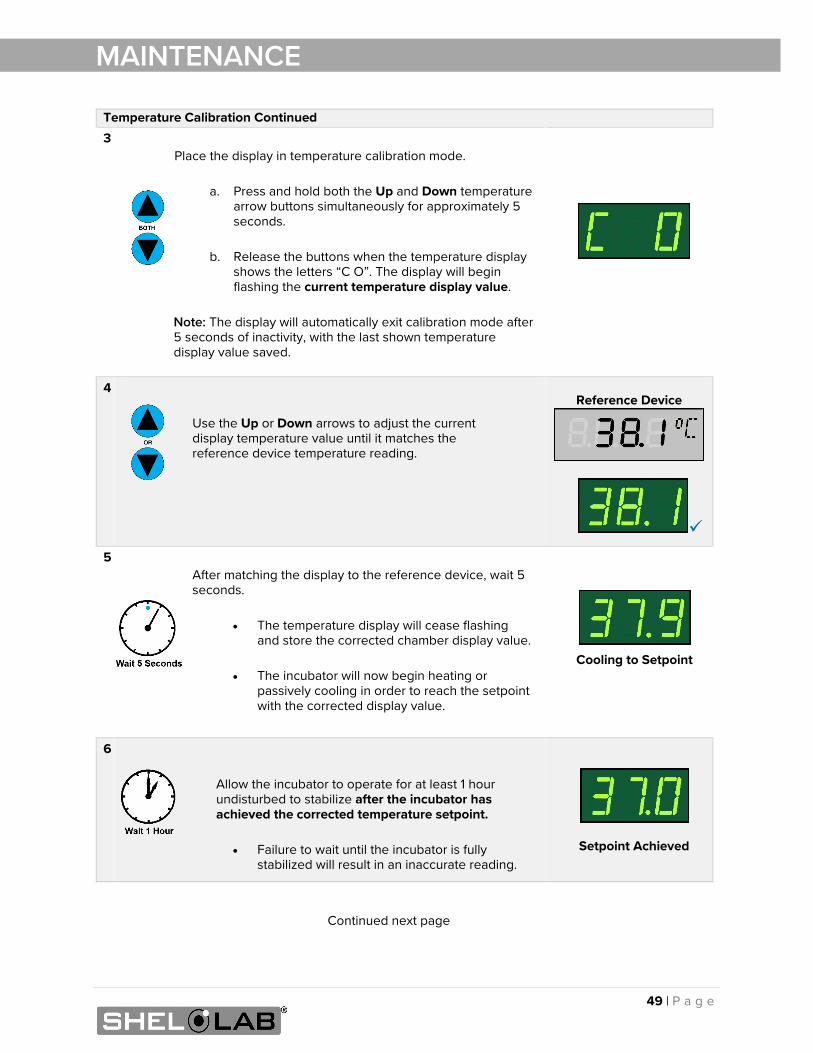
Temperature Calibration Continued 3
Place the display in temperature calibration mode.
a. Press and hold both the Up and Down temperature arrow buttons simultaneously for approximately 5 seconds.
b. Release the buttons when the temperature display shows the letters “C O”. The display will begin flashing the current temperature display value.
Note: The display will automatically exit calibration mode after 5 seconds of inactivity, with the last shown temperature display value saved.
4
Use the Up or Down arrows to adjust the current display temperature value until it matches the reference device temperature reading.
Reference Device
5 After matching the display to the reference device, wait 5 seconds.
• The temperature display will cease flashing and store the corrected chamber display value.
• The incubator will now begin heating or
passively cooling in order to reach the setpoint with the corrected display value.
Cooling to Setpoint
6
Allow the incubator to operate for at least 1 hour undisturbed to stabilize after the incubator has achieved the corrected temperature setpoint.
• Failure to wait until the incubator is fully
stabilized will result in an inaccurate reading.
Setpoint Achieved
50 | P a g e
MAINTENANCE
End of Procedure
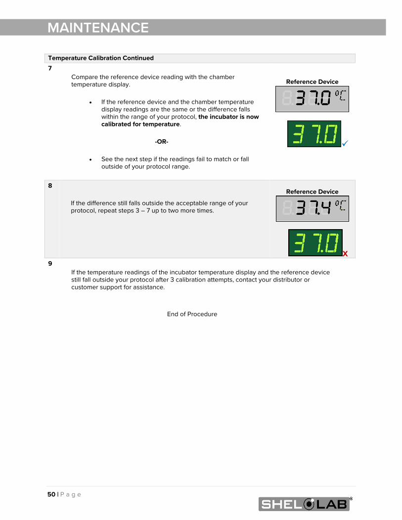
Temperature Calibration Continued 7
Compare the reference device reading with the chamber temperature display.
• If the reference device and the chamber temperature
display readings are the same or the difference falls within the range of your protocol, the incubator is now calibrated for temperature.
-OR-
• See the next step if the readings fail to match or fall
outside of your protocol range.
Reference Device
8
If the difference still falls outside the acceptable range of your protocol, repeat steps 3 – 7 up to two more times.
Reference Device
X 9
If the temperature readings of the incubator temperature display and the reference device still fall outside your protocol after 3 calibration attempts, contact your distributor or customer support for assistance.
51 | P a g e
MAINTENANCE
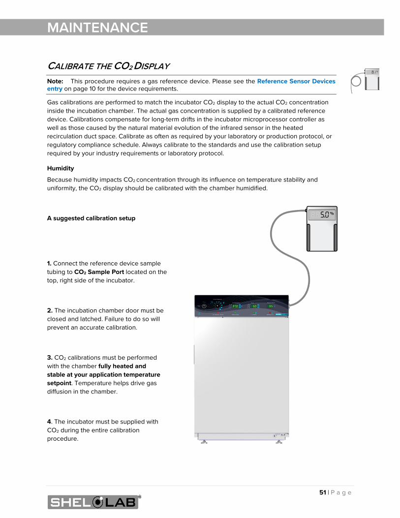
CALIBRATE THE CO2 DISPLAY Note: This procedure requires a gas reference device. Please see the Reference Sensor Devices entry on page 10 for the device requirements.
Gas calibrations are performed to match the incubator CO2 display to the actual CO2 concentration inside the incubation chamber. The actual gas concentration is supplied by a calibrated reference device. Calibrations compensate for long-term drifts in the incubator microprocessor controller as well as those caused by the natural material evolution of the infrared sensor in the heated recirculation duct space. Calibrate as often as required by your laboratory or production protocol, or regulatory compliance schedule. Always calibrate to the standards and use the calibration setup required by your industry requirements or laboratory protocol.
Humidity
Because humidity impacts CO2 concentration through its influence on temperature stability and uniformity, the CO2 display should be calibrated with the chamber humidified.
A suggested calibration setup
1. Connect the reference device sample tubing to CO2 Sample Port located on the top, right side of the incubator.
2. The incubation chamber door must be closed and latched. Failure to do so will prevent an accurate calibration.
3. CO2 calibrations must be performed with the chamber fully heated and stable at your application temperature setpoint. Temperature helps drive gas diffusion in the chamber.
4. The incubator must be supplied with CO2 during the entire calibration procedure.
52 | P a g e
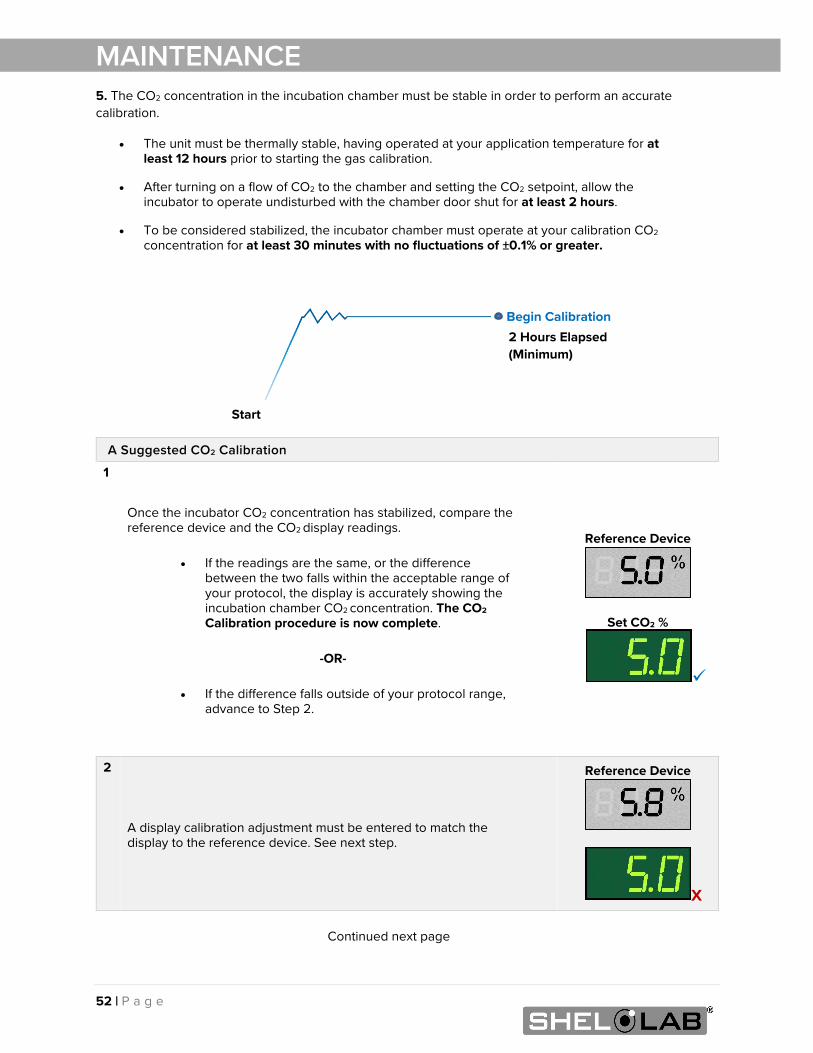
MAINTENANCE 5. The CO2 concentration in the incubation chamber must be stable in order to perform an accurate calibration.
• The unit must be thermally stable, having operated at your application temperature for at least 12 hours prior to starting the gas calibration.
• After turning on a flow of CO2 to the chamber and setting the CO2 setpoint, allow the incubator to operate undisturbed with the chamber door shut for at least 2 hours.
• To be considered stabilized, the incubator chamber must operate at your calibration CO2 concentration for at least 30 minutes with no fluctuations of ±0.1% or greater.
Continued next page
A Suggested CO2 Calibration
1
Once the incubator CO2 concentration has stabilized, compare the reference device and the CO2 display readings.
• If the readings are the same, or the difference between the two falls within the acceptable range of your protocol, the display is accurately showing the incubation chamber CO2 concentration. The CO2 Calibration procedure is now complete.
-OR-
• If the difference falls outside of your protocol range,
advance to Step 2.
Reference Device
Set CO2 %
2
A display calibration adjustment must be entered to match the display to the reference device. See next step.
Reference Device
X
Start
Begin Calibration 2 Hours Elapsed (Minimum)
53 | P a g e
MAINTENANCE
Continued next page
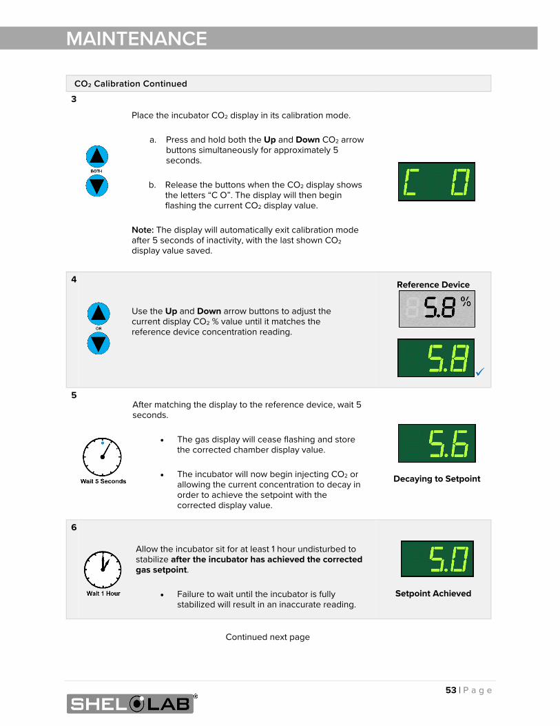
CO2 Calibration Continued
3
Place the incubator CO2 display in its calibration mode.
a. Press and hold both the Up and Down CO2 arrow buttons simultaneously for approximately 5 seconds.
b. Release the buttons when the CO2 display shows
the letters “C O”. The display will then begin flashing the current CO2 display value.
Note: The display will automatically exit calibration mode after 5 seconds of inactivity, with the last shown CO2 display value saved.
4
Use the Up and Down arrow buttons to adjust the current display CO2 % value until it matches the reference device concentration reading.
Reference Device
5 After matching the display to the reference device, wait 5 seconds.
• The gas display will cease flashing and store
the corrected chamber display value.
• The incubator will now begin injecting CO2 or allowing the current concentration to decay in order to achieve the setpoint with the corrected display value.
Decaying to Setpoint
6
Allow the incubator sit for at least 1 hour undisturbed to stabilize after the incubator has achieved the corrected gas setpoint.
• Failure to wait until the incubator is fully
stabilized will result in an inaccurate reading.
Setpoint Achieved
54 | P a g e
MAINTENANCE
End of Procedure
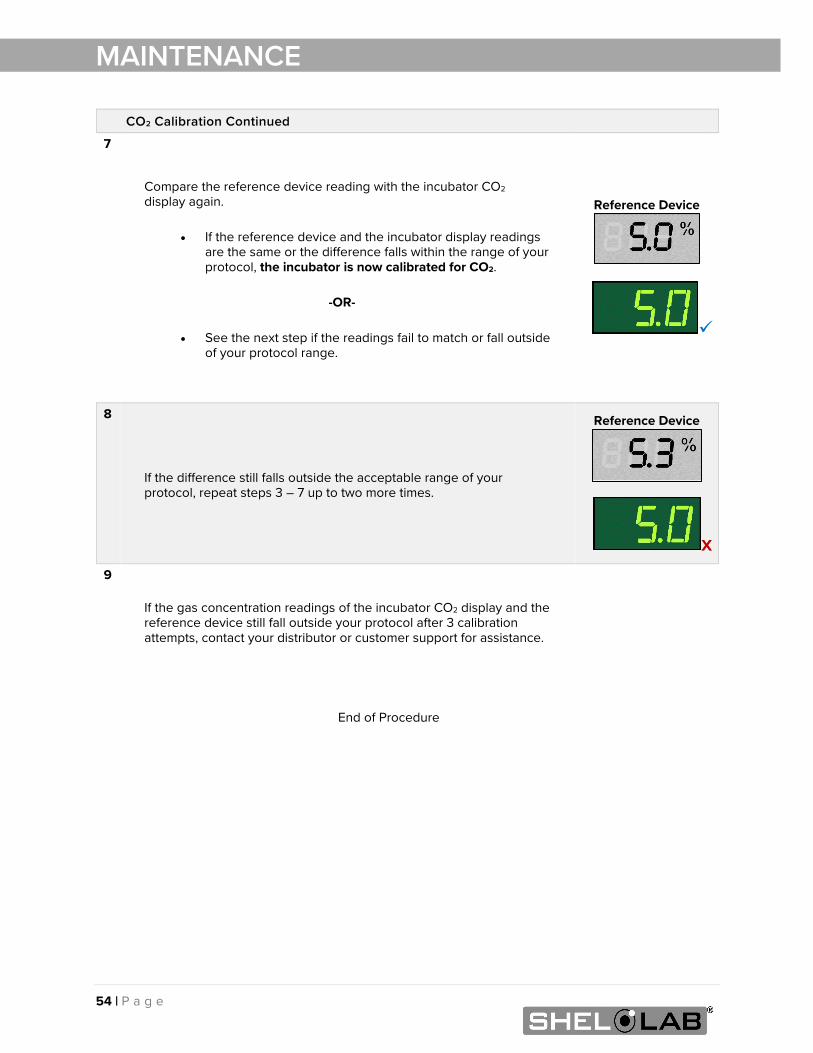
CO2 Calibration Continued
7
Compare the reference device reading with the incubator CO2 display again.
• If the reference device and the incubator display readings
are the same or the difference falls within the range of your protocol, the incubator is now calibrated for CO2.
-OR-
• See the next step if the readings fail to match or fall outside
of your protocol range.
Reference Device
8
If the difference still falls outside the acceptable range of your protocol, repeat steps 3 – 7 up to two more times.
Reference Device
X
9
If the gas concentration readings of the incubator CO2 display and the reference device still fall outside your protocol after 3 calibration attempts, contact your distributor or customer support for assistance.
55 | P a g e
MAINTENANCE
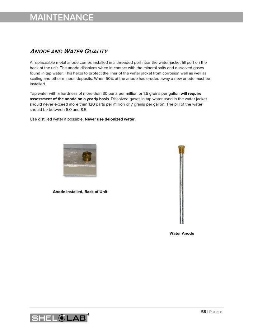
ANODE AND WATER QUALITY A replaceable metal anode comes installed in a threaded port near the water-jacket fill port on the back of the unit. The anode dissolves when in contact with the mineral salts and dissolved gases found in tap water. This helps to protect the liner of the water jacket from corrosion well as well as scaling and other mineral deposits. When 50% of the anode has eroded away a new anode must be installed.
Tap water with a hardness of more than 30 parts per million or 1.5 grains per gallon will require assessment of the anode on a yearly basis. Dissolved gases in tap water used in the water jacket should never exceed more than 120 parts per million or 7 grains per gallon. The pH of the water should be between 6.0 and 8.5.
Use distilled water if possible. Never use deionized water.
Anode Installed, Back of Unit
Water Anode

56 | P a g e
MAINTENANCE
57 | P a g e
UNIT SPECIFICATIONS
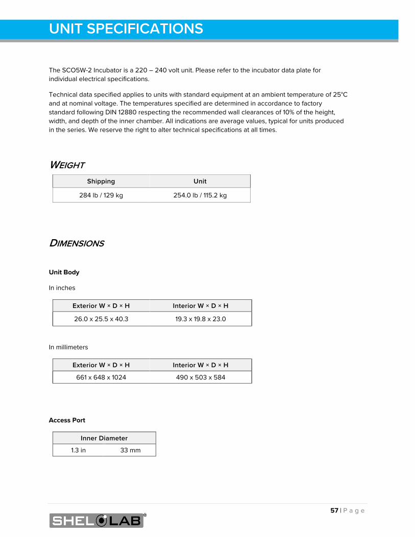
The SCO5W-2 Incubator is a 220 – 240 volt unit. Please refer to the incubator data plate for individual electrical specifications.
Technical data specified applies to units with standard equipment at an ambient temperature of 25°C and at nominal voltage. The temperatures specified are determined in accordance to factory standard following DIN 12880 respecting the recommended wall clearances of 10% of the height, width, and depth of the inner chamber. All indications are average values, typical for units produced in the series. We reserve the right to alter technical specifications at all times.
WEIGHT Shipping Unit
284 lb / 129 kg 254.0 lb / 115.2 kg
DIMENSIONS
Unit Body
In inches
Exterior W × D × H Interior W × D × H
26.0 x 25.5 x 40.3 19.3 x 19.8 x 23.0
In millimeters
Exterior W × D × H Interior W × D × H
661 x 648 x 1024 490 x 503 x 584
Access Port
Inner Diameter
1.3 in 33 mm
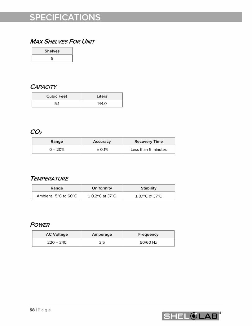
58 | P a g e
SPECIFICATIONS
MAX SHELVES FOR UNIT Shelves
8
CAPACITY Cubic Feet Liters
5.1 144.0
CO2 Range Accuracy Recovery Time
0 – 20% ± 0.1% Less than 5 minutes
TEMPERATURE Range Uniformity Stability
Ambient +5ºC to 60ºC ± 0.2ºC at 37ºC ± 0.1°C @ 37°C
POWER AC Voltage Amperage Frequency
220 – 240 3.5 50/60 Hz
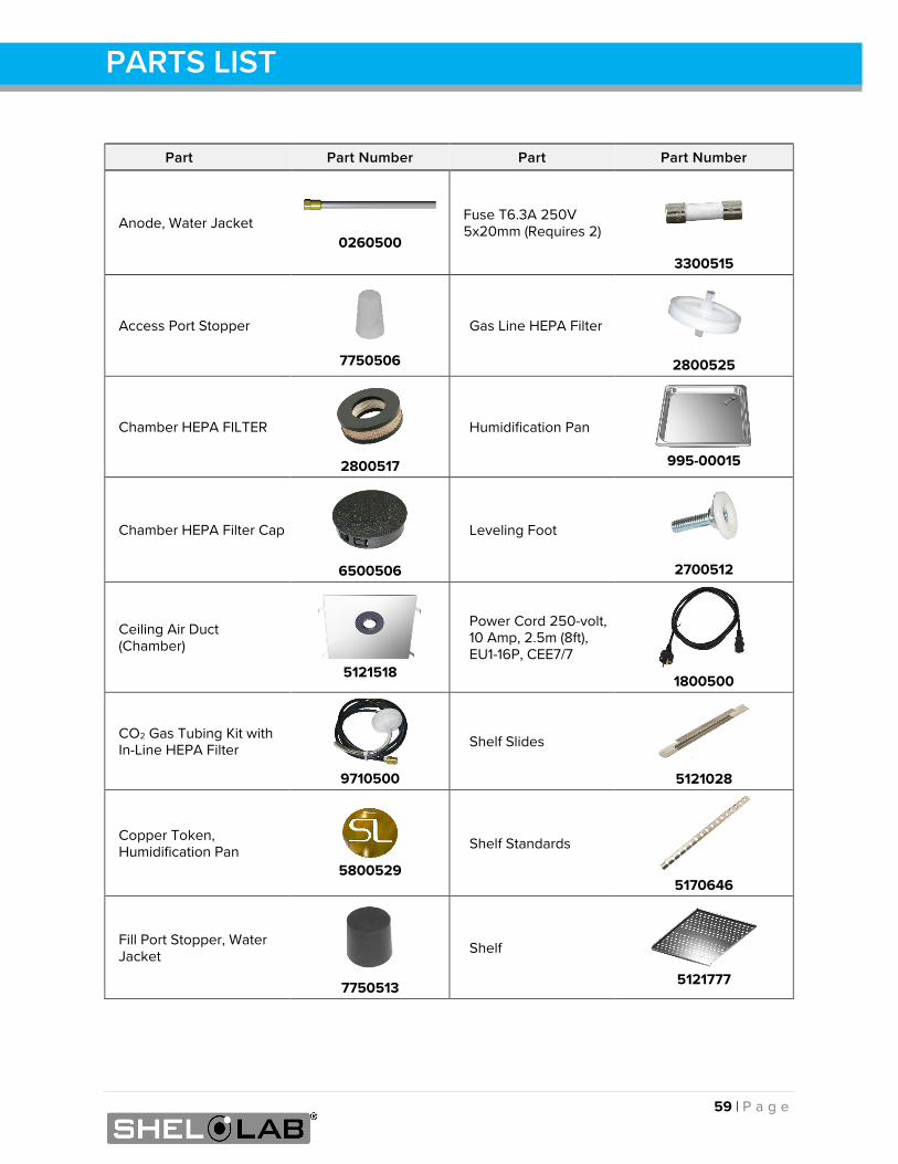
59 | P a g e
PARTS LIST
Part Part Number Part Part Number
Anode, Water Jacket
0260500
Fuse T6.3A 250V 5x20mm (Requires 2)
3300515
Access Port Stopper
7750506
Gas Line HEPA Filter
2800525
Chamber HEPA FILTER
2800517
Humidification Pan
995-00015
Chamber HEPA Filter Cap
6500506
Leveling Foot
2700512
Ceiling Air Duct (Chamber)
5121518
Power Cord 250-volt, 10 Amp, 2.5m (8ft), EU1-16P, CEE7/7
1800500
CO2 Gas Tubing Kit with In-Line HEPA Filter
9710500
Shelf Slides
5121028
Copper Token, Humidification Pan
5800529
Shelf Standards
5170646
Fill Port Stopper, Water Jacket
7750513
Shelf
5121777
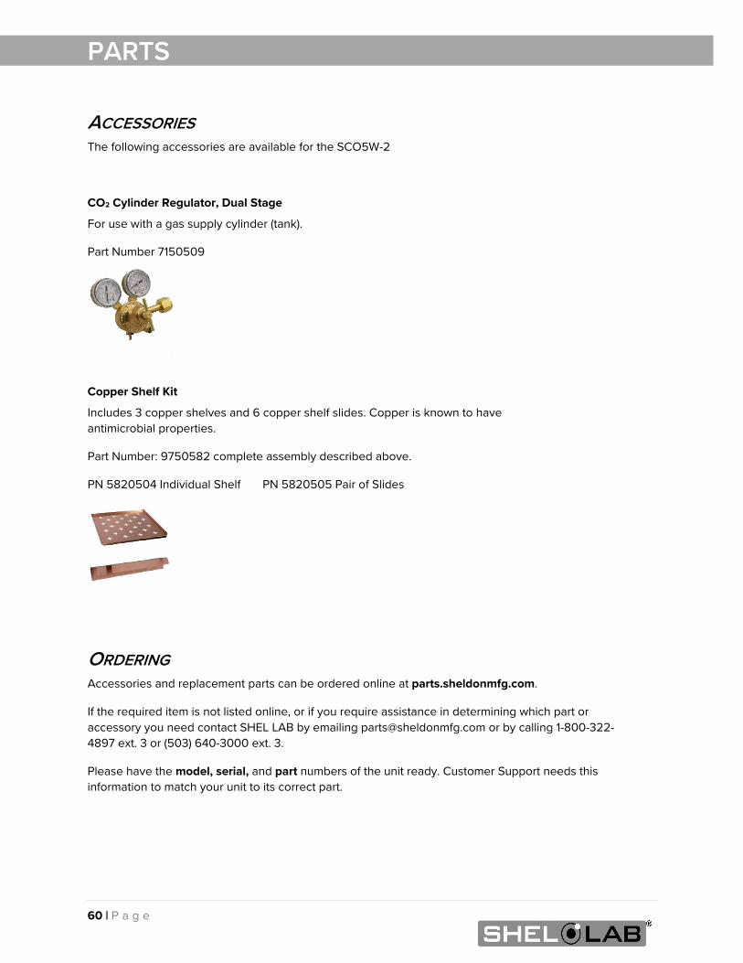
60 | P a g e
PARTS
ACCESSORIES The following accessories are available for the SCO5W-2
CO2 Cylinder Regulator, Dual Stage
For use with a gas supply cylinder (tank).
Part Number 7150509
Copper Shelf Kit
Includes 3 copper shelves and 6 copper shelf slides. Copper is known to have antimicrobial properties.
Part Number: 9750582 complete assembly described above.
PN 5820504 Individual Shelf PN 5820505 Pair of Slides
ORDERING Accessories and replacement parts can be ordered online at parts.sheldonmfg.com.
If the required item is not listed online, or if you require assistance in determining which part or accessory you need contact SHEL LAB by emailing [email protected] or by calling 1-800-322-4897 ext. 3 or (503) 640-3000 ext. 3.
Please have the model, serial, and part numbers of the unit ready. Customer Support needs this information to match your unit to its correct part.

61 | P a g e
PARTS

P.O. Box 627 Cornelius, OR 97113
USA
[email protected] sheldonmanufacturing.com
1-800-322-4897 (503) 640-3000
FAX: 503 640-1366