Installation & Operation Manual D 402 - BlueRidge...
32
1 of 32 © 2010 D 402 - 09/10 tekmarNet ® 2 House Control 402 D 402 09/10 HVAC Systems Replaces: 01/10 Installation & Operation Manual Menu House Control 402 Item VIEW Boil Exp Boil System Zones 1 2 3 4 Calls Pumps Benefits Energy efficiency through Outdoor Temperature Reset with Indoor Feedback Indoor Feedback minimizes the water temperature (increasing energy savings), and the efficiency of your mechanical equipment through integrated tekmarNet ® Thermostats Zone Synchronization reduces equipment cycling Auto Differential - Reduces boiler cycling Compact enclosure for flexible installation Simple zone expansion using Wiring Centers • • • • • • The House Control 402 is designed to operate as part of a complete hydronic heating system with tekmarNet ® 2 (tN2) thermostats. It can provide operation of two outdoor reset water temperatures such as radiant floor heating on the first temperature and baseboard or fan coil heating on the second temperature. In addition the control has Domestic Hot Water and Setpoint capabilities. It is easy to add more zones, add schedules or other convenient accessories through the use of the tekmarNet ® 4 (tN4) Expansion terminals. Features Single on-off, two-stage or modulating boiler Boiler outdoor reset temperature Mixing outdoor reset temperature Domestic Hot Water tank operation Setpoint operation Mix with variable speed injection, floating action, or proportional 0-10 V (dc), proportional 4-20 mA For use with tekmarNet ® 2 Thermostats Four 24 V (ac) powered zone valve outputs Expand to 24 zones per temperature using tekmarNet ® 4 expansion ports CSA C US Certified for use in USA and Canada • • • • • • • • • • Introduction
Transcript of Installation & Operation Manual D 402 - BlueRidge...
1 of 32 © 2010 D 402 - 09/10
tekmarNet®2 House Control 402D 402
09/10
HVAC Systems Replaces: 01/10
Installation & Operation Manual
Menu
House Control 402
Item
VIEW
Boil Exp Boil SystemZones1 2 3 4
Calls Pumps
Benefi tsEnergy efficiency through Outdoor Temperature Reset with Indoor Feedback
Indoor Feedback minimizes the water temperature (increasing energy savings), and the efficiency of your mechanical equipment through integrated tekmarNet® Thermostats
Zone Synchronization reduces equipment cycling
Auto Differential - Reduces boiler cycling
Compact enclosure for flexible installation
Simple zone expansion using Wiring Centers
•
•
•
•
•
•
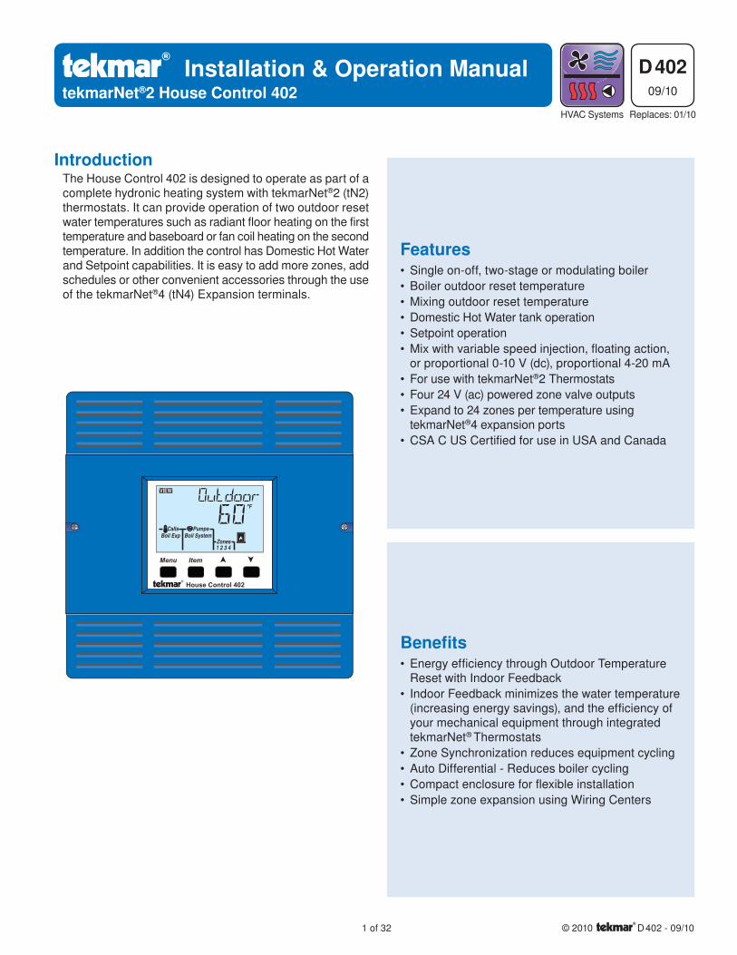
The House Control 402 is designed to operate as part of a complete hydronic heating system with tekmarNet®2 (tN2) thermostats. It can provide operation of two outdoor reset water temperatures such as radiant floor heating on the first temperature and baseboard or fan coil heating on the second temperature. In addition the control has Domestic Hot Water and Setpoint capabilities. It is easy to add more zones, add schedules or other convenient accessories through the use of the tekmarNet®4 (tN4) Expansion terminals.
FeaturesSingle on-off, two-stage or modulating boiler
Boiler outdoor reset temperature
Mixing outdoor reset temperature
Domestic Hot Water tank operation
Setpoint operation
Mix with variable speed injection, floating action, or proportional 0-10 V (dc), proportional 4-20 mA
For use with tekmarNet®2 Thermostats
Four 24 V (ac) powered zone valve outputs
Expand to 24 zones per temperature using tekmarNet®4 expansion ports
CSA C US Certified for use in USA and Canada
•
•
•
•
•
•
•
•
•
•
Introduction
© 2010 D 402 - 09/10 2 of 32
Table of Contents
Getting Started
Caution
Installation ......................................................................2
Preparation ................................................................ 2Physical Dimensions ................................................. 3Installation Location .................................................. 3Rough-In Wiring ........................................................ 3Sizing the Transformer .............................................. 4Control Wiring ........................................................... 4Sensor Wiring ............................................................ 7Testing the Sensor Wiring ......................................... 9Testing the Control Wiring ......................................... 9Max Heat ..................................................................10
Applications .................................................................. 11
User Interface ............................................................... 13
Display......................................................................13Symbols ...................................................................13Navigating The Display ............................................14Access Levels and Thermostat Lock ........................14Programming and Settings .......................................14View Menu ...............................................................15Adjust Menu ........................................................16-18
Monitor Menu ...........................................................19Toolbox Menu .......................................................... 20
Sequence of Operation ................................................21
tekmarNet® System ..................................................21Mix Temperature Reset Operation ...........................21Boiler Temperature Reset Operation ....................... 22Domestic Hot Water Tank Operation ....................... 23Setpoint Operation .................................................. 25Boiler Operation ...................................................... 25Domestic Hot Water Heat Source ............................27Pump Operation .......................................................27Energy Saving Features .......................................... 28
Troubleshooting ............................................................28
Error Messages .................................................. 28-30Frequently Asked Questions .............................. 30-31Job Record ...............................................................31
Technical Data ..............................................................32
Limited Warranty and Product Return Procedure ........32
Congratulations on the purchase of your new tekmarNet® House Control!
This manual covers the complete installation, programming and sequence of operation for this control. You will also find instruction on testing, commissioning, and troubleshooting the control and system that it operates.
Improper installation and operation of this control could result in damage to the equipment and possibly even personal injury or death. It is your responsibility to ensure that this control is safely installed according to all applicable codes and standards. This electronic control is not intended for use as a primary limit control. Other controls that are intended and certified as safety limits must be placed into
the control circuit. Do not attempt to service the control. Refer to qualified personnel for servicing. There are no user serviceable parts. Attempting to do so voids warranty and could result in damage to the equipment and possibly even personal injury or death.
Installation
The installer must ensure that this control and its wiring are isolated and/or shielded from strong sources of electromagnetic noise. Conversely, this Class B digital apparatus complies with Part 15 of the FCC Rules and meets all requirements of the Canadian Interference-Causing Equipment Regulations. However, if this control does cause harmful interference to radio or television reception, which is determined by turning the control off and on, the user is encouraged to try
to correct the interference by re-orientating or relocating the receiving antenna, relocating the receiver with respect to this control, and/or connecting the control to a different circuit from that to which the receiver is connected.
Cet appareil numérique de la classe B respecte toutes les exigences du Règlement sur le matériel brouilleur du Canada.
Radio Frequency Interference
Preparation
Tools Required --------------------------------------------------------------------------------------- ---------------------------------------------------------------------------------------
tekmar or jeweller screwdriver
Phillips head screwdriver
•
•
Needle-nose Pliers
Wire Stripper
•
•
3 of 32 © 2010 D 402 - 09/10
Materials Required ----------------------------------------------------------------------------------- -----------------------------------------------------------------------------------
(2) #10 x 1” Wood Screws
(3) Wire Nuts
18 AWG LVT Solid Wire (Low Voltage Connections)
•
•
•
14 AWG Solid Wire (Line Voltage Connections)
tekmar 009K (24 V (ac) transformer with 4” x 4” junction box)
Cable or Conduit Connectors
•
•
•
Power Required -------------------------------------------------------------------------------------- --------------------------------------------------------------------------------------
120 V (ac), 1-phase, 15 A service from circuit breaker panel
• Power disconnect (optional)•
Installation Location
When choosing the location for the control, consider the following:
Keep dry. Avoid potential leakage onto the control.RH 90% to 104°F (40°C).Non-condensing environment.
Do not expose to operating temperatures beyond 32-104°F (0-40°C)
Provide adequate ventilation.
Keep away from equipment, appliances or other sources of electrical interference.
•
•
•
•
•
Locate the control near pumps and/or zone valves if possible.
Provide easy access for wiring, viewing and adjusting the control.
Mount approximately 5 ft. (1.5 m) off the finished floor.
Install the electrical junction box to a wall using #10 x 1” wood screws. Wall anchors are recommended when mounting to sheet rock wallboard or masonry.
•
•
•
•
Rough-In Wiring
Line Voltage Wiring----------------------------------------------------------------------------------------------------------------------------------------------------------------------
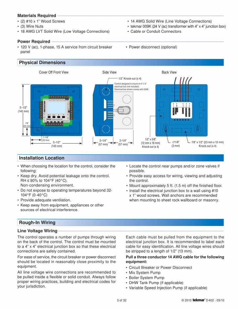
The control operates a number of pumps through wiring on the back of the control. The control must be mounted to a 4” x 4” electrical junction box so that these electrical connections are safely contained.
For ease of service, the circuit breaker or power disconnect should be located in reasonably close proximity to the equipment.
All line voltage wire connections are recommended to be pulled inside a flexible or solid conduit. Always follow proper wiring practices, building and electrical codes for your jurisdiction.
Each cable must be pulled from the equipment to the electrical junction box. It is recommended to label each cable for easy identification. All line voltage wires should be stripped to a length of 1/2” (13 mm).
Pull a three conductor 14 AWG cable for the following equipment:
Circuit Breaker or Power Disconnect
Mix System Pump
Boiler System Pump
DHW Tank Pump (if applicable)
Variable Speed Injection Pump (if applicable)
•
•
•
•
•
Physical Dimensions
Side ViewCover Off Front View Back View
5–1/2”(140 mm)
5–1/2”(140 mm)
Menu
House Control 402
Item
+
Mix
ComBoil
Out
DHW
VlvC VlvC VlvCZone 3Zone 1 Zone 2 Zone 4
Made in Canada
VlvC
Com
Zone 1
H8007B
Zone 2 Zone 3 Zone 4tN2 tN2 tN2 tN2 tN2 tN2 tN2 tN2 C
Floating ActionClsOpn
Sensors - No PowerCall
Call
tN4
tN4
CC
Mod
dc/
mA
Boil E
xp.
Mix
Exp.
SetpointDHW
Use at least 167°F(75°C) conductorsRC
Input Power
Stag
e 2
Stag
e 1
1–1/8”(30 mm)
7/8”(22 mm)
CL
1/2” Knock-out (x 4)
Control designed to mount on 4” x 4” electrical box (not included).Electrical box shown comes with 009K
2–1/4”(57 mm)
2–1/4”(57 mm)
Boil System Pum
p
Mix System
Pump
DHW Pum
p
VariableSpeed Pum
p
Pump Power L
7/8” x 1/2” (23 mm x 12 mm)Knock-out (x 4)
1/2” x 5/8”(12 mm x 16 mm)Knock-out (x 4)
∅1/8”(3 mm)
© 2010 D 402 - 09/10 4 of 32
The control requires an external transformer. A tekmar Transformer 009 (or 009K which includes a 4”x 4” electrical box) can supply up to 40 VA, and includes an in-line fuse to protect the transformer and control.
In order to correctly size the external transformer, all loads connected to the control must be taken into account.
When adding up the loads, consider the following:
tekmarNet®2 Thermostats draw approximately 2 VA each.
Each zone valve must be sized for peak load. This can be obtained by multiplying the peak current draw (in Amps) by 24 V (ac).
•
•
If using a Floating Action mixing valve, add the VA draw for the actuating motor. A tekmar Actuating Motor 741 draws 1.5 VA during normal operation.
The total power capacity of the power supply should be larger than the total load of all the devices connected to the control. This total load must not exceed 100 VA. Multiple tekmar Transformer 009’s can be wired together to increase total VA capacity.
The following chart is provided to simplify transformer sizing:
•
Zone 1 2 3 4
Thermostat Load
Zone Valve LoadFloating
Action (VA)Control
Load (VA)
Total Zone Load + + + + + 2
Transformer must exceed:
VA
Sizing the Transformer
Control Wiring
Line Voltage Wiring----------------------------------------------------------------------------------------------------------------------------------------------------------------------
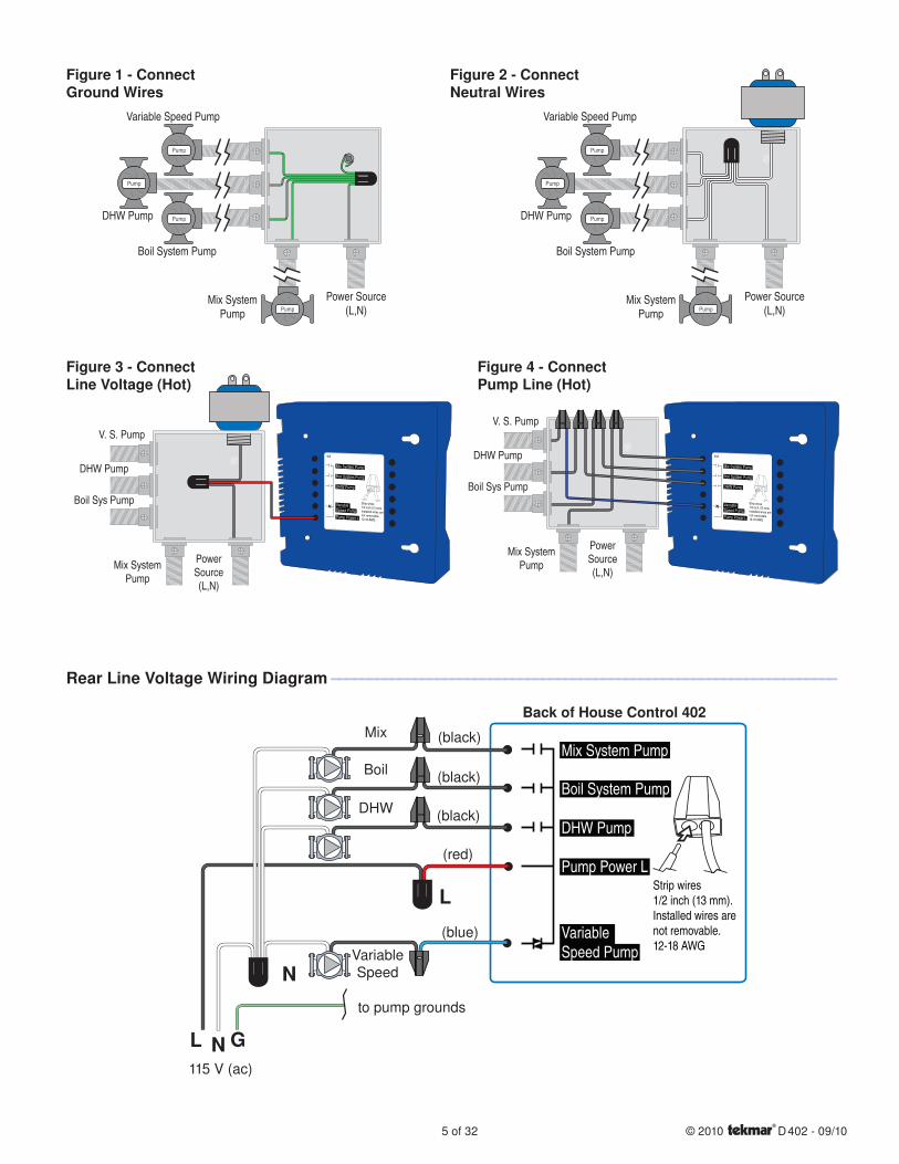
Ground the PumpsConnect the pump grounds to the power supply ground as shown in Figure 1. The ground wire must also be grounded to the electrical box.
Wire the Pump NeutralsConnect the Neutral (N) wires from each pump and wire to the 115 V (ac) Neutral (N) wire. If the transformer has been mounted to this electrical box, connect its neutral wire with this group. This is shown in Figure 2.
•
•
Wire the Pump Power (L)Connect the 115 V (ac) line voltage (L) wire to the red Pump Power (L) wire on the back of the House Control and to the 115 V (ac) side of the transformer. Use a wire nut or approved connector. See Figure 3.
Wire the PumpsWire each remaining line voltage pump wire into the push-in wire connector of the corresponding pump lead on the back of the House Control. This is shown in Figure 4.
•
•
CAUTION: TURN ALL POWER OFF BEFORE PERFORMING ANY WIRING.
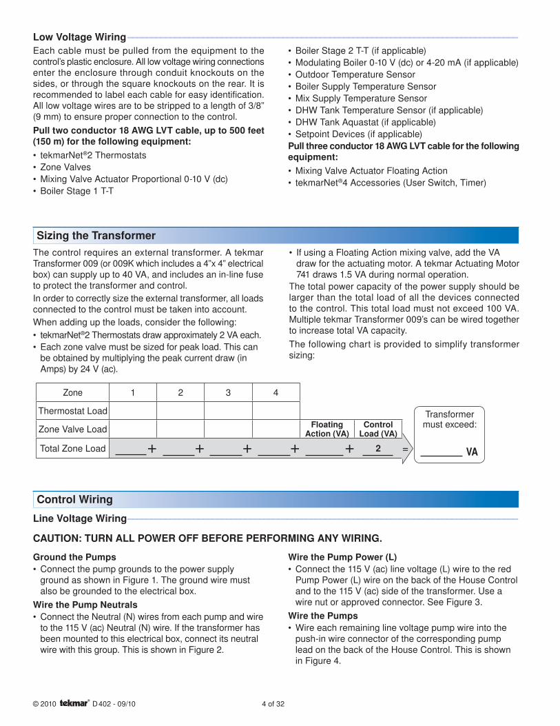
Each cable must be pulled from the equipment to the control’s plastic enclosure. All low voltage wiring connections enter the enclosure through conduit knockouts on the sides, or through the square knockouts on the rear. It is recommended to label each cable for easy identification. All low voltage wires are to be stripped to a length of 3/8” (9 mm) to ensure proper connection to the control.
Pull two conductor 18 AWG LVT cable, up to 500 feet (150 m) for the following equipment:
tekmarNet®2 Thermostats
Zone Valves
Mixing Valve Actuator Proportional 0-10 V (dc)
Boiler Stage 1 T-T
•
•
•
•
Boiler Stage 2 T-T (if applicable)
Modulating Boiler 0-10 V (dc) or 4-20 mA (if applicable)
Outdoor Temperature Sensor
Boiler Supply Temperature Sensor
Mix Supply Temperature Sensor
DHW Tank Temperature Sensor (if applicable)
DHW Tank Aquastat (if applicable)
Setpoint Devices (if applicable)
Pull three conductor 18 AWG LVT cable for the following equipment:
Mixing Valve Actuator Floating Action
tekmarNet®4 Accessories (User Switch, Timer)
•
•
•
•
•
•
•
•
•
•
Low Voltage Wiring ----------------------------------------------------------------------------------- -----------------------------------------------------------------------------------
5 of 32 © 2010 D 402 - 09/10
DHW Pump
Mix System Pump
Power Source (L,N)
V. S. Pump
Boil Sys PumpBoil System Pump
Mix System Pump
DHW Pump
VariableSpeed PumpPump Power L
402
Strip wires1/2 inch (13 mm).Installed wires arenot removable.12-18 AWG
Variable Speed Pump
DHW Pump
Boil System Pump
Mix System Pump
Power Source (L,N)
Pump
Pump
Pump
Pump
Variable Speed Pump
DHW Pump
Boil System Pump
Mix System Pump
Power Source (L,N)
Pump
Pump
Pump
Pump
Figure 1 - Connect Ground Wires
Boil System Pump
Mix System Pump
DHW Pump
VariableSpeed PumpPump Power L
402
Strip wires1/2 inch (13 mm).Installed wires arenot removable.12-18 AWG
V. S. Pump
DHW Pump
Boil Sys Pump
Mix System Pump
Power Source (L,N)
Figure 2 - Connect Neutral Wires
Figure 3 - Connect Line Voltage (Hot)
Figure 4 - Connect Pump Line (Hot)
Mix
Boil
DHW
Variable Speed
115 V (ac)
NL G
to pump grounds
N
L
Back of House Control 402
Strip wires1/2 inch (13 mm).Installed wires arenot removable.12-18 AWG
(blue)
(red)
(black)
(black)
(black)
Boil System Pump
Mix System Pump
DHW Pump
VariableSpeed Pump
Pump Power L
Rear Line Voltage Wiring Diagram ------------------------------------------------------------------- -------------------------------------------------------------------
© 2010 D 402 - 09/10 6 of 32
External Power SupplyIt is strongly recommended that a transformer with an in-line fuse be used in order to protect the transformer from high currents. The tekmar Transformer 009 includes a fuse.
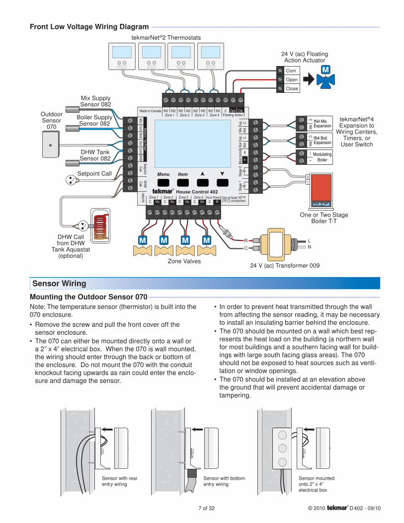
Connect the 24 V (ac) leads from the transformer to the C and R terminals marked “Input Power” on the 402.
tN2 ThermostatsThe 402 is designed to operate with tekmarNet®2 Thermostats. They provide the heating and cooling control for each zone, and communicate with any other tekmarNet® device on the system.
Connect the tN2 terminals from each thermostat to the corresponding tN2 terminals for each zone on the 402.
Zone ValvesWire the zone valves to the C and Vlv terminals on the 402.
End switches on zone valves are not required when using the 402.
tN4 Expansion TerminalsThe 402 uses the Expansion tN4 and C terminals to communicate with additional thermostats, setpoint controls, and other tekmarNet® devices. There are two sets of tN4 and C terminals on the 402.
Boil Exp.To add additional boiler water temperature zones (typically baseboard or fan coil zones) to the system, install a tekmarNet® Wiring Center.
Connect the tN4 and C Boil Exp. terminals on the 402 to the corresponding tN4 and C Expansion terminals on the external Wiring Center.
Mix Exp.The 402 has the capacity to expand the number of mixing zones in the system beyond the four on board zones. To add additional mix water temperature zones (typically radiant floor zones) to the system, install a tekmarNet®
Wiring Center.
Connect the tN4 and C Mix Exp. terminals on the 402 to the corresponding tN4 and C Expansion terminals on the external Wiring Center.
•
•
•
•
•
•
Low Voltage Wiring ----------------------------------------------------------------------------------- -----------------------------------------------------------------------------------
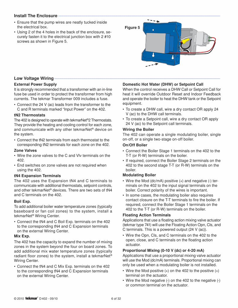
Ensure that the pump wires are neatly tucked inside the electrical box.
Using 2 of the 4 holes in the back of the enclosure, se-curely fasten it to the electrical junction box with 2 #10 screws as shown in Figure 5.
•
•
Install The Enclosure --------------------------------------------------------------------------------- ---------------------------------------------------------------------------------
Figure 5
Domestic Hot Water (DHW) or Setpoint CallWhen the control receives a DHW Call or Setpoint Call for heat it will override Outdoor Reset and Indoor Feedback and operate the boiler to heat the DHW tank or the Setpoint equipment.
To create a DHW call, wire a dry contact OR apply 24 V (ac) to the DHW call terminals.
To create a Setpoint call, wire a dry contact OR apply 24 V (ac) to the Setpoint call terminals.
Wiring the BoilerThe 402 can operate a single modulating boiler, single on-off, or a single two-stage on-off boiler.
On/Off BoilerConnect the Boiler Stage 1 terminals on the 402 to the T-T (or R-W) terminals on the boiler.
If required, connect the Boiler Stage 2 terminals on the 402 to the second stage T-T (or R-W) terminals on the boiler.
Modulating BoilerWire the Mod (dc/mA) positive (+) and negative (-) ter-minals on the 402 to the input signal terminals on the boiler. Correct polarity of the wires is important.
In some cases, the modulating boiler also requires contact closure on the T-T terminals to fire the boiler. If required, connect the Boiler Stage 1 terminals on the 402 to the T-T (or R-W) terminals on the boiler.
Floating Action TerminalsApplications that use a floating action mixing valve actuator (tekmar type 741) will use the Floating Action Opn, Cls, and C terminals. This is a powered output (24 V (ac)).
Wire the Opn, Cls, and C terminals on the 402 to the open, close, and C terminals on the floating action actuator.
Proportional Mixing (0-10 V (dc) or 4-20 mA)Applications that use a proportional mixing valve actuator will use the Mod (dc/mA) terminals. Proportional mixing can only be used when a modulating boiler is not installed.
Wire the Mod positive (+) on the 402 to the positive (+) terminal on the actuator.
Wire the Mod negative (-) on the 402 to the negative (-) or common terminal on the actuator.
•
•
•
•
•
•
•
•
•
7 of 32 © 2010 D 402 - 09/10
R
C
L
N
Com
Open
Close
ExpansiontN4 Boil
CtN4
ModulatingBoiler
—+
ExpansiontN4 Mix
CtN4
21
WC
WC
Menu
House Control 402
Item
+
Mix
ComBoil
Out
DHW
VlvC VlvC VlvCZone 3Zone 1 Zone 2 Zone 4
Made in Canada
VlvC
Com
Zone 1
H8007B
Zone 2 Zone 3 Zone 4tN2 tN2 tN2 tN2 tN2 tN2 tN2 tN2 C
Floating ActionClsOpn
Sensors - No PowerCall
Call
tN4
tN4
CC
Mod
dc/
mA
Boil E
xp.
Mix
Exp.
SetpointDHW
Use at least 167°F(75°C) conductorsRC
Input Power
Stag
e 2
Stag
e 1
Zone Valves24 V (ac) Transformer 009
DHW Callfrom DHW
Tank Aquastat (optional)
Setpoint Call
Outdoor Sensor
070
Mix Supply Sensor 082
Boiler Supply Sensor 082
DHW Tank Sensor 082
One or Two Stage Boiler T-T
tekmarNet®2 Thermostats
24 V (ac) Floating Action Actuator
Front Low Voltage Wiring Diagram ------------------------------------------------------------------- -------------------------------------------------------------------
Sensor Wiring
Note: The temperature sensor (thermistor) is built into the 070 enclosure.
Remove the screw and pull the front cover off the sensor enclosure.
The 070 can either be mounted directly onto a wall or a 2” x 4” electrical box. When the 070 is wall mounted, the wiring should enter through the back or bottom of the enclosure. Do not mount the 070 with the conduit knockout facing upwards as rain could enter the enclo-sure and damage the sensor.
•
•
In order to prevent heat transmitted through the wall from affecting the sensor reading, it may be necessary to install an insulating barrier behind the enclosure.
The 070 should be mounted on a wall which best rep-resents the heat load on the building (a northern wall for most buildings and a southern facing wall for build-ings with large south facing glass areas). The 070 should not be exposed to heat sources such as venti-lation or window openings.
The 070 should be installed at an elevation above the ground that will prevent accidental damage or tampering.
•
•
•
Mounting the Outdoor Sensor 070 -------------------------------------------------------------------- --------------------------------------------------------------------
Sensor with bottomentry wiring
Sensor with rearentry wiring
Sensor mountedonto 2" x 4"electrical box
tekmarNet®4Expansion to
Wiring Centers,Timers, or
User Switch
© 2010 D 402 - 09/10 8 of 32
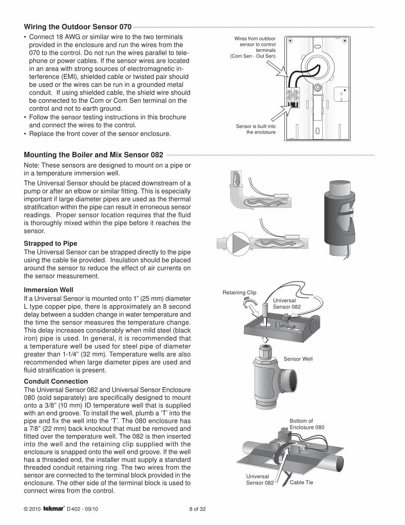
Connect 18 AWG or similar wire to the two terminals provided in the enclosure and run the wires from the 070 to the control. Do not run the wires parallel to tele-phone or power cables. If the sensor wires are located in an area with strong sources of electromagnetic in-terference (EMI), shielded cable or twisted pair should be used or the wires can be run in a grounded metal conduit. If using shielded cable, the shield wire should be connected to the Com or Com Sen terminal on the control and not to earth ground.
Follow the sensor testing instructions in this brochure and connect the wires to the control.
Replace the front cover of the sensor enclosure.
•
•
•
Wiring the Outdoor Sensor 070 ----------------------------------------------------------------------- -----------------------------------------------------------------------
Wires from outdoorsensor to control
terminals(Com Sen - Out Sen)
Sensor is built intothe enclosure
Mounting the Boiler and Mix Sensor 082 ------------------------------------------------------------- -------------------------------------------------------------
Note: These sensors are designed to mount on a pipe or in a temperature immersion well.
The Universal Sensor should be placed downstream of a pump or after an elbow or similar fitting. This is especially important if large diameter pipes are used as the thermal stratification within the pipe can result in erroneous sensor readings. Proper sensor location requires that the fluid is thoroughly mixed within the pipe before it reaches the sensor.
Strapped to PipeThe Universal Sensor can be strapped directly to the pipe using the cable tie provided. Insulation should be placed around the sensor to reduce the effect of air currents on the sensor measurement.
Immersion WellIf a Universal Sensor is mounted onto 1” (25 mm) diameter L type copper pipe, there is approximately an 8 second delay between a sudden change in water temperature and the time the sensor measures the temperature change. This delay increases considerably when mild steel (black iron) pipe is used. In general, it is recommended that a temperature well be used for steel pipe of diameter greater than 1-1/4” (32 mm). Temperature wells are also recommended when large diameter pipes are used and fluid stratification is present.
Conduit ConnectionThe Universal Sensor 082 and Universal Sensor Enclosure 080 (sold separately) are specifically designed to mount onto a 3/8” (10 mm) ID temperature well that is supplied with an end groove. To install the well, plumb a ‘T’ into the pipe and fix the well into the ‘T’. The 080 enclosure has a 7/8” (22 mm) back knockout that must be removed and fitted over the temperature well. The 082 is then inserted into the well and the retaining clip supplied with the enclosure is snapped onto the well end groove. If the well has a threaded end, the installer must supply a standard threaded conduit retaining ring. The two wires from the sensor are connected to the terminal block provided in the enclosure. The other side of the terminal block is used to connect wires from the control.
Bottom of Enclosure 080
UniversalSensor 082 Cable Tie
Sensor Well
Retaining Clip
UniversalSensor 082
9 of 32 © 2010 D 402 - 09/10
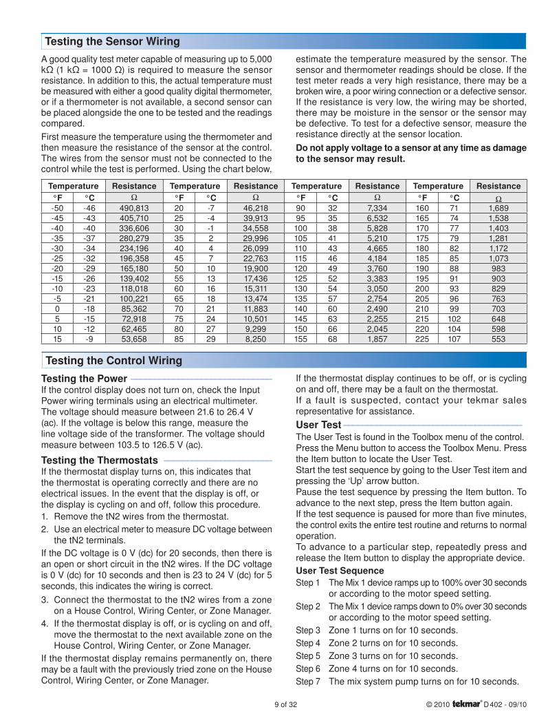
A good quality test meter capable of measuring up to 5,000 kΩ (1 kΩ = 1000 Ω) is required to measure the sensor resistance. In addition to this, the actual temperature must be measured with either a good quality digital thermometer, or if a thermometer is not available, a second sensor can be placed alongside the one to be tested and the readings compared.
First measure the temperature using the thermometer and then measure the resistance of the sensor at the control. The wires from the sensor must not be connected to the control while the test is performed. Using the chart below,
estimate the temperature measured by the sensor. The sensor and thermometer readings should be close. If the test meter reads a very high resistance, there may be a broken wire, a poor wiring connection or a defective sensor. If the resistance is very low, the wiring may be shorted, there may be moisture in the sensor or the sensor may be defective. To test for a defective sensor, measure the resistance directly at the sensor location.
Do not apply voltage to a sensor at any time as damage to the sensor may result.
Testing the Sensor Wiring
Temperature Resistance Temperature Resistance Temperature Resistance Temperature Resistance°F °C °F °C °F °C °F °C-50 -46 490,813 20 -7 46,218 90 32 7,334 160 71 1,689-45 -43 405,710 25 -4 39,913 95 35 6,532 165 74 1,538-40 -40 336,606 30 -1 34,558 100 38 5,828 170 77 1,403-35 -37 280,279 35 2 29,996 105 41 5,210 175 79 1,281-30 -34 234,196 40 4 26,099 110 43 4,665 180 82 1,172-25 -32 196,358 45 7 22,763 115 46 4,184 185 85 1,073-20 -29 165,180 50 10 19,900 120 49 3,760 190 88 983-15 -26 139,402 55 13 17,436 125 52 3,383 195 91 903-10 -23 118,018 60 16 15,311 130 54 3,050 200 93 829-5 -21 100,221 65 18 13,474 135 57 2,754 205 96 7630 -18 85,362 70 21 11,883 140 60 2,490 210 99 7035 -15 72,918 75 24 10,501 145 63 2,255 215 102 64810 -12 62,465 80 27 9,299 150 66 2,045 220 104 59815 -9 53,658 85 29 8,250 155 68 1,857 225 107 553
Testing the Control Wiring
Testing the Power ------------------------------ ------------------------------If the control display does not turn on, check the Input Power wiring terminals using an electrical multimeter. The voltage should measure between 21.6 to 26.4 V (ac). If the voltage is below this range, measure the line voltage side of the transformer. The voltage should measure between 103.5 to 126.5 V (ac).
Testing the Thermostats ----------------------- -----------------------If the thermostat display turns on, this indicates that the thermostat is operating correctly and there are no electrical issues. In the event that the display is off, or the display is cycling on and off, follow this procedure.
1. Remove the tN2 wires from the thermostat.
2. Use an electrical meter to measure DC voltage between the tN2 terminals.
If the DC voltage is 0 V (dc) for 20 seconds, then there is an open or short circuit in the tN2 wires. If the DC voltage is 0 V (dc) for 10 seconds and then is 23 to 24 V (dc) for 5 seconds, this indicates the wiring is correct.
3. Connect the thermostat to the tN2 wires from a zone on a House Control, Wiring Center, or Zone Manager.
4. If the thermostat display is off, or is cycling on and off, move the thermostat to the next available zone on the House Control, Wiring Center, or Zone Manager.
If the thermostat display remains permanently on, there may be a fault with the previously tried zone on the House Control, Wiring Center, or Zone Manager.
If the thermostat display continues to be off, or is cycling on and off, there may be a fault on the thermostat.If a fault is suspected, contact your tekmar sales representative for assistance.
User Test -------------------------------------- --------------------------------------The User Test is found in the Toolbox menu of the control.Press the Menu button to access the Toolbox Menu. Press the Item button to locate the User Test.Start the test sequence by going to the User Test item and pressing the ‘Up’ arrow button.Pause the test sequence by pressing the Item button. To advance to the next step, press the Item button again.If the test sequence is paused for more than five minutes, the control exits the entire test routine and returns to normal operation.To advance to a particular step, repeatedly press and release the Item button to display the appropriate device.
User Test SequenceStep 1 The Mix 1 device ramps up to 100% over 30 seconds
or according to the motor speed setting.
Step 2 The Mix 1 device ramps down to 0% over 30 seconds or according to the motor speed setting.
Step 3 Zone 1 turns on for 10 seconds.
Step 4 Zone 2 turns on for 10 seconds.
Step 5 Zone 3 turns on for 10 seconds.
Step 6 Zone 4 turns on for 10 seconds.
Step 7 The mix system pump turns on for 10 seconds.
© 2010 D 402 - 09/10 10 of 32
Step 8 The DHW pump turns on for 10 seconds.
Step 9 The boiler system pump turns on for 10 seconds.
Step 10 During the boiler test step, zone relays 1 through 4 turn on, the mix system pump turns on, and the boil system pump turns on. The mixing device operates up to 20%. This ensures there is a location for heat to move when the boiler is turned on.
If the Boil Type is 1 Stage, the boiler stage 1 relay is closed for 10 seconds and then opened.
If the Boil Type is 2 Stage, the boiler stage 1 relay is closed for 10 seconds, then the boiler stage 2 relay is closed for 10 seconds and then both relays are opened.
If Boiler Type is modulating 0 - 10, the boiler stage 1 relay is closed for 10 seconds and the modulating output operates at 50 % [5 V (dc)].
If Boiler Type is modulating 4 - 20, the boiler stage 1 relay is closed for 10 seconds and the modulating output operates at 50 % (12 mA).
Step 11 Control returns to normal operation.
Testing the Variable Speed Injection Pump ---- ----Activate the User Test sequence and pause at Step 1 by pressing the Item button once the injection pump is operating at 100%. Using an electrical meter, measure the voltage between the variable speed pump and a neutral. The voltage should measure between 103.5 V (ac) and 126.5 V (ac).
Testing the Zone Output ---------------------- ----------------------Activate the User Test sequence and pause at Step 3 by pressing the Item button once Zone 1 turns on. Using an electrical meter, measure the voltage between the zone valve and the common (C) terminals. The voltage should measure between 21.6 V (ac) and 26.4 V (ac). Repeat for Zones 2, 3, and 4.
Testing the Mix System Pump ----------------- -----------------Activate the User Test sequence and pause at Step 7 by pressing the Item button once the mix system pump turns on. Using an electrical meter, measure the voltage between the mix system pump and a neutral. The voltage should measure between 103.5 V (ac) and 126.5 V (ac).
•
•
•
•
Testing the DHW Pump ------------------------ ------------------------Activate the User Test sequence and pause at Step 8 by pressing the Item button once the DHW pump turns on. Using an electrical meter, measure the voltage between the DHW pump and a neutral. The voltage should measure between 103.5 V (ac) and 126.5 V (ac).
Testing the Boiler System Pump --------------- ---------------Activate the User Test sequence and pause at Step 9 by pressing the Item button once the boiler system pump turns on. Using an electrical meter, measure the voltage between the boiler system pump and a neutral. The voltage should measure between 103.5 V (ac) and 126.5 V (ac).
Testing the Boiler Stage 1 Contact--------------------------Activate the User Test sequence and pause at Step 10 by pressing the Item button once the boiler stage 1 turns on. Using an electrical meter, measure for continuity over the boiler stage 1 terminals.
Testing the Boiler Stage 2 Contact--------------------------This test applies for 2 stage on-off boilers only. Activate the User Test sequence and pause at Step 10 by pressing the Item button once the boiler stage 2 turns on. Using an electrical meter, measure for continuity over the boiler stage 2 terminals.
Testing the Boiler Modulating Output ---------- ----------This test applies for modulating boilers only.Active the User Test sequence and pause at Step 10 by pressing the Item button once the boiler stage 1 turns on. Using an electrical meter, measure for either a 5 V (dc) or 12 mA signal. The Boil Type setting selects whether the signal is V (dc) or mA.
Testing the DHW Call -------------------------- --------------------------Remove all wires from the DHW Call terminals. The control display should show no DHW Call. Reconnect wires. Then apply either a short circuit or 24 V (ac) over the DHW Call terminals. The control should now show a DHW Call.
Testing the Setpoint Call ---------------------- ----------------------Remove all wires from the Setpoint Call terminals. The control display should show no Setpoint Call. Reconnect wires. Then apply either a short circuit or 24 V (ac) over the Setpoint Call terminals. The control should now show a Setpoint Call.
The control has a function called Max Heat. In this mode, the control turns on and operates the system up to the maximum set temperatures as long as there is a call for heat. Use this mode to run the circulators during system start-up and commissioning, purging air from the piping. This feature is useful when drying sheet rock and paint in the building.
To enable Max Heat, enter the Toolbox Menu and find Max Heat. Use the up arrow to select ‘On’.
When a space heating call is present, the boiler will run to maintain a target of Boil Design + 10°F (+ 6°C).(One can purge the system using this test and leave
•
the boiler un-powered. This will prevent heat from en-tering the system during the purge.)
When a DHW Call or Setpoint Call is present, the boiler will operate at the DHW exchange or Setpoint temperature settings.
WWSD and DHW Priority is disabled during Max Heat mode.
When Max Heat is on the display will show ‘Max Heat Test’.
Max Heat will automatically turn off after 24 hours.
To Cancel Max Heat, go to Max Heat in the Toolbox menu and use the down arrow to select ‘Off’.
•
•
•
•
Max Heat
11 of 32 © 2010 D 402 - 09/10
Applications
Mix
Boil
DHW
Variable Speed
(P4)
(P1)
(P3)
(P2)
115 V (ac)
NL G
to pump grounds
N
L
Back of House Control 402
Strip wires1/2 inch (13 mm).Installed wires arenot removable.12-18 AWG
R
C
L
N
ExpansiontN4 Boil
CtN4
ExpansiontN4 Mix
CtN4
(blue)
(red)
(black)
(black)
(black)
1
Menu
House Control 402
Item
+M
ixCom
BoilO
utDHW
VlvC VlvC VlvCZone 3Zone 1 Zone 2 Zone 4
Made in Canada
VlvC
Com
Zone 1
H8007B
Zone 2 Zone 3 Zone 4tN2 tN2 tN2 tN2 tN2 tN2 tN2 tN2 C
Floating ActionClsOpn
Sensors - No PowerCall
CalltN
4tN
4C
CM
od d
c/m
ABo
il Exp
.M
ix Ex
p.Setpoint
DHW
Use at least 167°F(75°C) conductorsRC
Input Power
Stag
e 2
Stag
e 1
Boil System Pump
Mix System Pump
DHW Pump
VariableSpeed Pump
Pump Power L
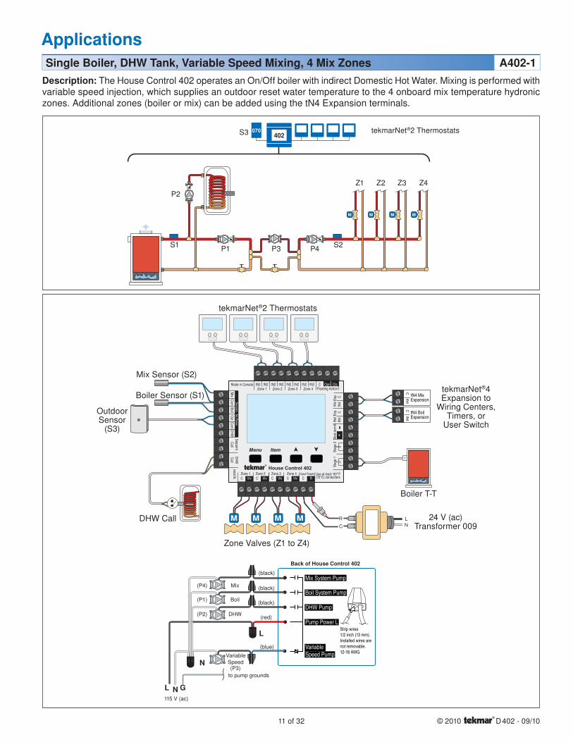
Description: The House Control 402 operates an On/Off boiler with indirect Domestic Hot Water. Mixing is performed with variable speed injection, which supplies an outdoor reset water temperature to the 4 onboard mix temperature hydronic zones. Additional zones (boiler or mix) can be added using the tN4 Expansion terminals.
Single Boiler, DHW Tank, Variable Speed Mixing, 4 Mix Zones A402-1
402070S3
S2S1
Outdoor Sensor
(S3)
tekmarNet®2 Thermostats
Boiler T-T
24 V (ac)Transformer 009
Mix Sensor (S2)
Boiler Sensor (S1)
DHW Call
Zone Valves (Z1 to Z4)
tekmarNet®4Expansion to
Wiring Centers,Timers, or
User Switch
tekmarNet®2 Thermostats
P1
P2
P3 P4
Z1 Z2 Z3 Z4
© 2010 D 402 - 09/10 12 of 32
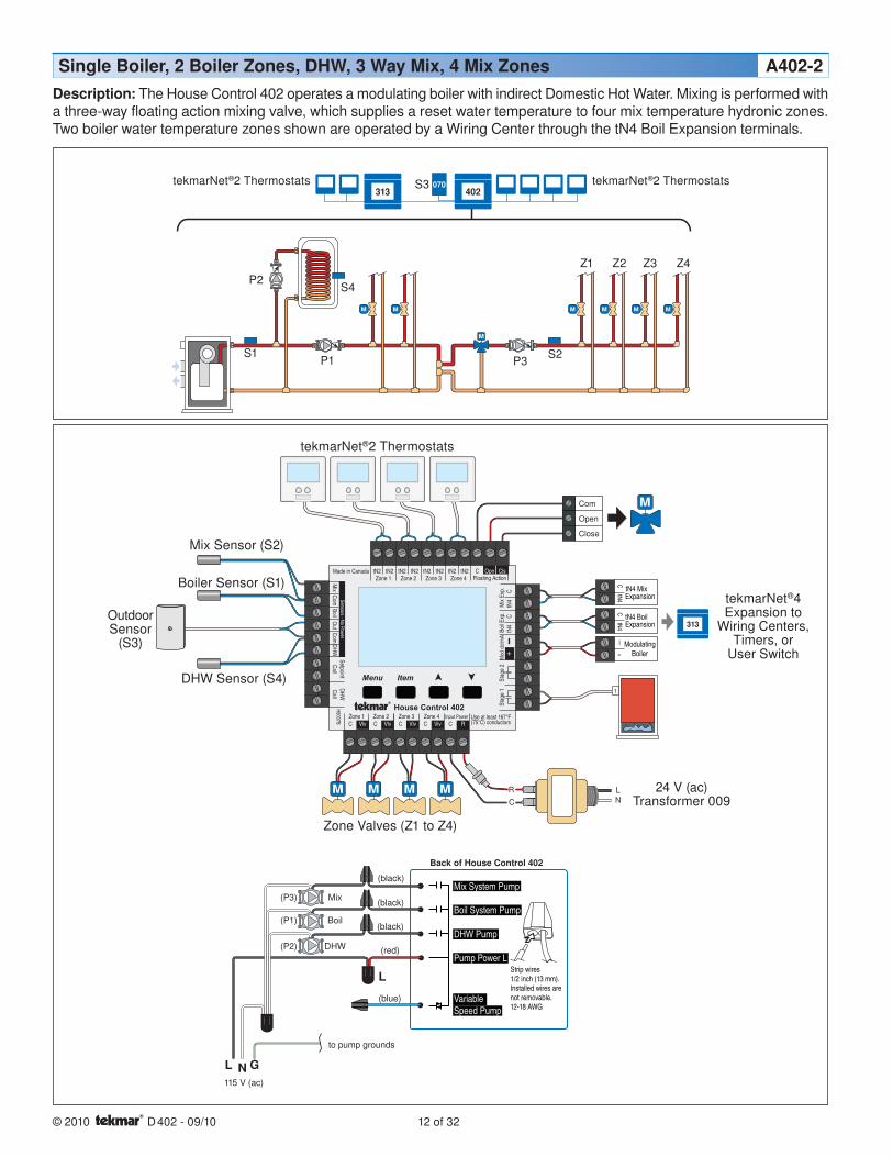
Description: The House Control 402 operates a modulating boiler with indirect Domestic Hot Water. Mixing is performed with a three-way floating action mixing valve, which supplies a reset water temperature to four mix temperature hydronic zones. Two boiler water temperature zones shown are operated by a Wiring Center through the tN4 Boil Expansion terminals.
Mix
Boil
DHW
(P3)
(P1)
(P2)
115 V (ac)
NL G
to pump grounds
L
Back of House Control 402
Strip wires1/2 inch (13 mm).Installed wires arenot removable.12-18 AWG
R
C
L
N
Com
Open
Close
ExpansiontN4 Boil
CtN4
ModulatingBoiler
—+
ExpansiontN4 Mix
CtN4
(blue)
(red)
(black)
(black)
(black)
1
313
Menu
House Control 402
Item
+
Mix
ComBoil
Out
DHW
VlvC VlvC VlvCZone 3Zone 1 Zone 2 Zone 4
Made in Canada
VlvC
Com
Zone 1
H8007B
Zone 2 Zone 3 Zone 4tN2 tN2 tN2 tN2 tN2 tN2 tN2 tN2 C
Floating ActionClsOpn
Sensors - No PowerCall
Call
tN4
tN4
CC
Mod
dc/
mA
Boil E
xp.
Mix
Exp.
SetpointDHW
Use at least 167°F(75°C) conductorsRC
Input Power
Stag
e 2
Stag
e 1
Boil System Pump
Mix System Pump
DHW Pump
VariableSpeed Pump
Pump Power L
402070
313
Single Boiler, 2 Boiler Zones, DHW, 3 Way Mix, 4 Mix Zones A402-2
S3
S1 S2
S4
24 V (ac)Transformer 009
Zone Valves (Z1 to Z4)
DHW Sensor (S4)
Boiler Sensor (S1)
Mix Sensor (S2)
tekmarNet®2 Thermostats
Outdoor Sensor
(S3)
tekmarNet®4Expansion to
Wiring Centers,Timers, or
User Switch
tekmarNet®2 ThermostatstekmarNet®2 Thermostats
P1
P2
P3
Z1 Z2 Z3 Z4
13 of 32 © 2010 D 402 - 09/10
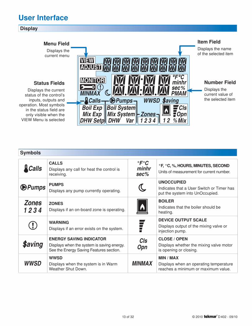
CallsCALLSDisplays any call for heat the control is receiving.
Pumps PUMPSDisplays any pump currently operating.
Zones1 2 3 4
ZONESDisplays if an on-board zone is operating.
WARNINGDisplays if an error exists on the system.
SavingENERGY SAVING INDICATORDisplays when the system is saving energy. See the Energy Saving Features section.
WWSDWWSDDisplays when the system is in Warm Weather Shut Down.
°F°C minhrsec%
°F, °C, %, HOURS, MINUTES, SECONDUnits of measurement for current number.
UNOCCUPIEDIndicates that a User Switch or Timer has put the system into UnOccupied.
BOILERIndicates that the boiler should be heating.
DEVICE OUTPUT SCALEDisplays output of the mixing valve or injection pump.
ClsOpn
CLOSE / OPENDisplays whether the mixing valve motor is opening or closing.
MAXMINMIN / MAXDisplays when an operating temperature reaches a minimum or maximum value.
Symbols
Display
MONITOR
VIEWADJUST
MAXMIN
Boil ExpMix Exp
DHW Setp
Boil SystemMix System Zones
ClsOpn
DHW Var 1 2 3 4 1 2 Mix
AM
minsec
hr
PMCalls Pumps WWSD Saving
Item FieldDisplays the name of the selected item
Number FieldDisplays the current value of the selected item
Status FieldsDisplays the current
status of the control’s inputs, outputs and
operation. Most symbols in the status field are only visible when the
VIEW Menu is selected
Menu FieldDisplays the
current menu
User Interface
© 2010 D 402 - 09/10 14 of 32
Navigating The Display
Menu Button ----------------------------------------------------------------------------------------- -----------------------------------------------------------------------------------------
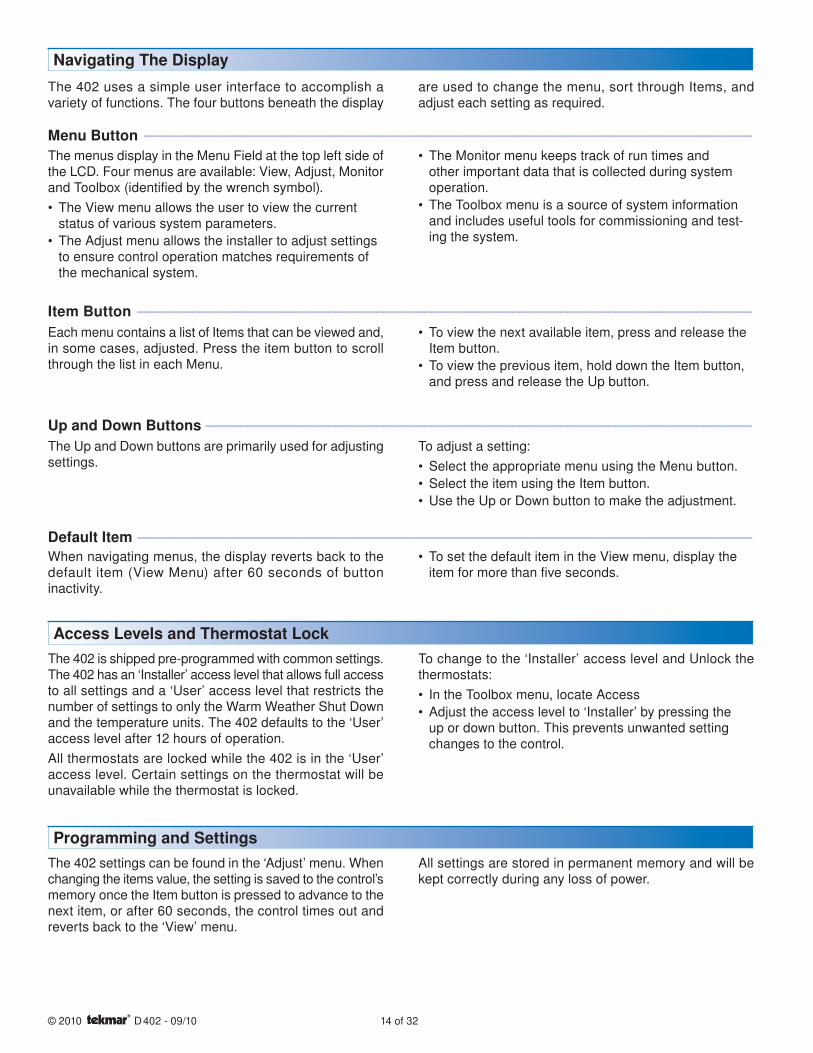
The 402 uses a simple user interface to accomplish a variety of functions. The four buttons beneath the display
are used to change the menu, sort through Items, and adjust each setting as required.
The menus display in the Menu Field at the top left side of the LCD. Four menus are available: View, Adjust, Monitor and Toolbox (identified by the wrench symbol).
The View menu allows the user to view the current status of various system parameters.
The Adjust menu allows the installer to adjust settings to ensure control operation matches requirements of the mechanical system.
•
•
The Monitor menu keeps track of run times and other important data that is collected during system operation.
The Toolbox menu is a source of system information and includes useful tools for commissioning and test-ing the system.
•
•
Item Button ------------------------------------------------------------------------------------------ ------------------------------------------------------------------------------------------
Each menu contains a list of Items that can be viewed and, in some cases, adjusted. Press the item button to scroll through the list in each Menu.
To view the next available item, press and release the Item button.
To view the previous item, hold down the Item button, and press and release the Up button.
•
•
Up and Down Buttons -------------------------------------------------------------------------------- --------------------------------------------------------------------------------
The Up and Down buttons are primarily used for adjusting settings.
To adjust a setting:
Select the appropriate menu using the Menu button.
Select the item using the Item button.
Use the Up or Down button to make the adjustment.
•
•
•
Default Item ------------------------------------------------------------------------------------------ ------------------------------------------------------------------------------------------
When navigating menus, the display reverts back to the default item (View Menu) after 60 seconds of button inactivity.
To set the default item in the View menu, display the item for more than five seconds.
•
Access Levels and Thermostat LockThe 402 is shipped pre-programmed with common settings. The 402 has an ‘Installer’ access level that allows full access to all settings and a ‘User’ access level that restricts the number of settings to only the Warm Weather Shut Down and the temperature units. The 402 defaults to the ‘User’ access level after 12 hours of operation.
All thermostats are locked while the 402 is in the ‘User’ access level. Certain settings on the thermostat will be unavailable while the thermostat is locked.
To change to the ‘Installer’ access level and Unlock the thermostats:
In the Toolbox menu, locate Access
Adjust the access level to ‘Installer’ by pressing the up or down button. This prevents unwanted setting changes to the control.
•
•
Programming and SettingsThe 402 settings can be found in the ‘Adjust’ menu. When changing the items value, the setting is saved to the control’s memory once the Item button is pressed to advance to the next item, or after 60 seconds, the control times out and reverts back to the ‘View’ menu.
All settings are stored in permanent memory and will be kept correctly during any loss of power.
15 of 32 © 2010 D 402 - 09/10
Item Field Range DescriptionVIEW
Zones
Calls Pumps
-76 to 149°F(-60.0 to 65.0°C)
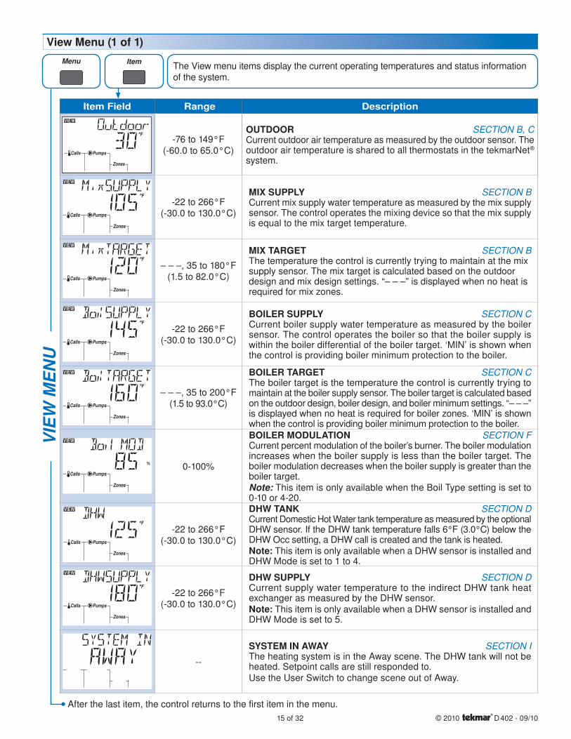
OUTDOOR SECTION B, CCurrent outdoor air temperature as measured by the outdoor sensor. The outdoor air temperature is shared to all thermostats in the tekmarNet® system.
VIEW
Zones
Calls Pumps
-22 to 266°F(-30.0 to 130.0°C)
MIX SUPPLY SECTION BCurrent mix supply water temperature as measured by the mix supply sensor. The control operates the mixing device so that the mix supply is equal to the mix target temperature.
VIEW
Zones
Calls Pumps
– – –, 35 to 180°F(1.5 to 82.0°C)
MIX TARGET SECTION BThe temperature the control is currently trying to maintain at the mix supply sensor. The mix target is calculated based on the outdoor design and mix design settings. “– – –” is displayed when no heat is required for mix zones.
VIEW
Zones
Calls Pumps
-22 to 266°F(-30.0 to 130.0°C)
BOILER SUPPLY SECTION CCurrent boiler supply water temperature as measured by the boiler sensor. The control operates the boiler so that the boiler supply is within the boiler differential of the boiler target. ‘MIN’ is shown when the control is providing boiler minimum protection to the boiler.
VIEW
Zones
Calls Pumps
– – –, 35 to 200°F(1.5 to 93.0°C)
BOILER TARGET SECTION CThe boiler target is the temperature the control is currently trying to maintain at the boiler supply sensor. The boiler target is calculated based on the outdoor design, boiler design, and boiler minimum settings. “– – –” is displayed when no heat is required for boiler zones. ‘MIN’ is shown when the control is providing boiler minimum protection to the boiler.
VIEW
Zones
Calls Pumps0-100%
BOILER MODULATION SECTION FCurrent percent modulation of the boiler’s burner. The boiler modulation increases when the boiler supply is less than the boiler target. The boiler modulation decreases when the boiler supply is greater than the boiler target.Note: This item is only available when the Boil Type setting is set to 0-10 or 4-20.
-22 to 266°F(-30.0 to 130.0°C)
DHW TANK SECTION DCurrent Domestic Hot Water tank temperature as measured by the optional DHW sensor. If the DHW tank temperature falls 6°F (3.0°C) below the DHW Occ setting, a DHW call is created and the tank is heated.Note: This item is only available when a DHW sensor is installed and DHW Mode is set to 1 to 4.
-22 to 266°F(-30.0 to 130.0°C)
DHW SUPPLY SECTION DCurrent supply water temperature to the indirect DHW tank heat exchanger as measured by the DHW sensor.Note: This item is only available when a DHW sensor is installed and DHW Mode is set to 5.
--
SYSTEM IN AWAY SECTION IThe heating system is in the Away scene. The DHW tank will not be heated. Setpoint calls are still responded to.Use the User Switch to change scene out of Away.
VIE
W M
EN
UView Menu (1 of 1)
The View menu items display the current operating temperatures and status information of the system.
After the last item, the control returns to the first item in the menu.
© 2010 D 402 - 09/10 16 of 32
Item Field Range Access Description Set to
ADJUST -60 to 45°F(-51.0 to 7.0°C)
Default = 10°F(-12.0°C)
Installer
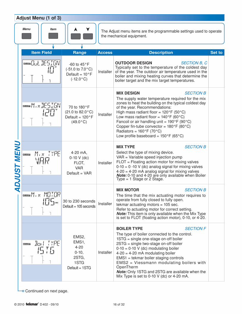
OUTDOOR DESIGN SECTION B, CTypically set to the temperature of the coldest day of the year. The outdoor air temperature used in the boiler and mixing heating curves that determine the boiler target and the mix target temperatures.
ADJUST 70 to 180°F(21.0 to 82.0°C)
Default = 120°F (49.0°C)
Installer
MIX DESIGN SECTION B
The supply water temperature required for the mix zones to heat the building on the typical coldest day of the year. Recommendations:High mass radiant floor = 120°F (50°C)Low mass radiant floor = 140°F (60°C)Fancoil or air handling unit = 190°F (90°C)Copper fin-tube convector = 180°F (80°C)Radiators = 160°F (70°C)Low profile baseboard = 150°F (65°C)
ADJUST4-20 mA,
0-10 V (dc)
FLOT,
VAR
Default = VAR
Installer
MIX TYPE SECTION B
Select the type of mixing device.VAR = Variable speed injection pumpFLOT = Floating action motor for mixing valves0-10 = 0 -10 V (dc) analog signal for mixing valves4-20 = 4-20 mA analog signal for mixing valvesNote: 0-10 and 4-20 are only available when Boiler Type = 1 Stage or 2 Stage.
ADJUST
sec 30 to 230 seconds
Default = 105 secondsInstaller
MIX MOTOR SECTION B
The time that the mix actuating motor requires to operate from fully closed to fully open.tekmar actuating motors = 105 sec. Refer to actuating motor for correct setting.Note: This item is only available when the Mix Type is set to FLOT (floating action motor), 0-10, or 4-20.
EMS2,
EMS1,
4-20
0-10,
2STG,
1STG
Default = 1STG
Installer
BOILER TYPE SECTION F
The type of boiler connected to the control.1STG = single one-stage on-off boiler2STG = single two-stage on-off boiler0-10 = 0-10 V (dc) modulating boiler4-20 = 4-20 mA modulating boilerEMS1 = tekmar boiler staging controlsEMS2 = Viessmann modulating boilers with OpenThermNote: Only 1STG and 2STG are available when the Mix Type is set to 0-10 V (dc) or 4-20 mA.
AD
JUS
T M
EN
UAdjust Menu (1 of 3)
The Adjust menu items are the programmable settings used to operate the mechanical equipment.
Continued on next page.

17 of 32 © 2010 D 402 - 09/10
Item Field Range Access Description Set to
VIEW70 to 200°F
(21.0 to 93.5°C)
Default = 180°F
(82.0°C)
Installer
BOILER DESIGN SECTION C
The supply water temperature required for the boiler zones to heat the building on the typical coldest day of the year. Recommendations:High mass radiant floor = 120°F (50°C)Low mass radiant floor = 140°F (60°C)Fancoil or air handling unit = 190°F (90°C)Copper fin-tube convector = 180°F (80°C)Radiators = 160°F (70°C)Low profile baseboard = 150°F (65°C)
OFF, 80 to 180°F
(26.5 to 82.0°C)
Default = 140°F
(60.0°C)
Installer
BOILER MINIMUM SECTION B, C
The minimum allowed boiler target temperature and temperature at which the mixing device begins to provide boiler protection against cold return water temperatures. The mixing valve or variable speed injection pump operate at low percent output when the boiler supply temperature drops below this setting.Recommendations:Condensing gas or electric boiler = OFFNon-condensing gas and oil boilers = 140°F (60°C)Note: If Boiler Type is 0-10 V (dc), 4-20 mA, EMS1 or EMS2, this setting is defaulted to Off. The mixing device does not provide boiler protection when Boiler Type is set to EMS1 or EMS2.
ADJUST
sec
10 to 230 seconds
Default = 30 seconds
Installer
BOILER MOTOR SECTION F
The time required for the modulating actuating motor to fully open the gas valve or ramp the burner fan from off to full speed on a modulating boiler. Set to 30 seconds unless otherwise recommended by the boiler manufacturer.Note: This item is only available when the Boiler Type is 0-10 V (dc) or 4-20 mA.
ADJUST
0 to 50%
Default = 0%Installer
MINIMUM MODULATION SECTION F
The minimum percent modulation of the boiler burner.Note: This item is only available when the Boiler Type is 0-10 V (dc) or 4-20 mA.
ADJUST
sec0 to 3:00 minutes
Default = 10 seconds
Installer
MODULATION DELAY SECTION F
Delay time between the burner firing and the boiler releasing to modulation.Note: This item is only available when the Boiler Type is 0-10 V (dc) or 4-20 mA.
ADJUST
Off or On
Default = OffInstaller
FLUSHING SECTION G
Set to On when a domestic hot water tank is used to heat the building. When On, the control ensures that each zone is operated at least once daily to prevent stagnation.
Adjust Menu (2 of 3)A
DJU
ST
ME
NU
Continued on next page.
© 2010 D 402 - 09/10 18 of 32
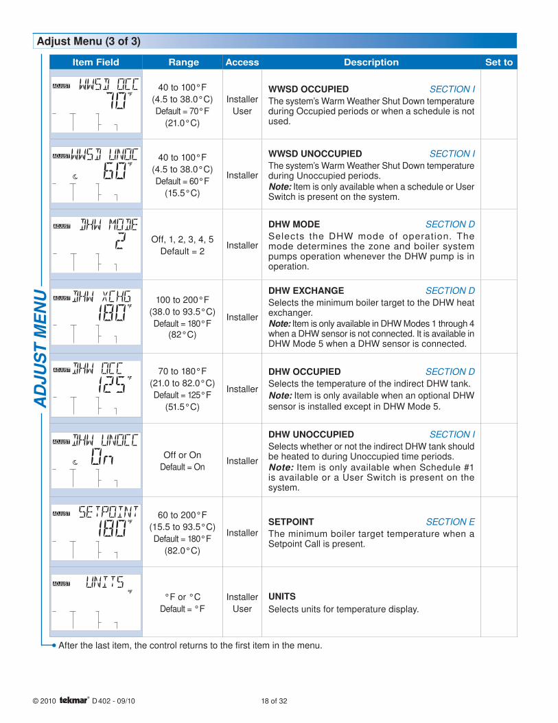
Item Field Range Access Description Set to
ADJUST 40 to 100°F
(4.5 to 38.0°C)
Default = 70°F
(21.0°C)
Installer
User
WWSD OCCUPIED SECTION I
The system’s Warm Weather Shut Down temperature during Occupied periods or when a schedule is not used.
ADJUST 40 to 100°F
(4.5 to 38.0°C)
Default = 60°F
(15.5°C)
Installer
WWSD UNOCCUPIED SECTION I
The system’s Warm Weather Shut Down temperature during Unoccupied periods.Note: Item is only available when a schedule or User Switch is present on the system.
Off, 1, 2, 3, 4, 5
Default = 2Installer
DHW MODE SECTION D
Selects the DHW mode of operation. The mode determines the zone and boiler system pumps operation whenever the DHW pump is in operation.
100 to 200°F
(38.0 to 93.5°C)
Default = 180°F (82°C)
Installer
DHW EXCHANGE SECTION D
Selects the minimum boiler target to the DHW heat exchanger.Note: Item is only available in DHW Modes 1 through 4 when a DHW sensor is not connected. It is available in DHW Mode 5 when a DHW sensor is connected.
70 to 180°F
(21.0 to 82.0°C)
Default = 125°F
(51.5°C)
Installer
DHW OCCUPIED SECTION D
Selects the temperature of the indirect DHW tank.
Note: Item is only available when an optional DHW sensor is installed except in DHW Mode 5.
ADJUST
Off or On
Default = OnInstaller
DHW UNOCCUPIED SECTION I
Selects whether or not the indirect DHW tank should be heated to during Unoccupied time periods.Note: Item is only available when Schedule #1 is available or a User Switch is present on the system.
ADJUST 60 to 200°F
(15.5 to 93.5°C)
Default = 180°F
(82.0°C)
InstallerSETPOINT SECTION E
The minimum boiler target temperature when a Setpoint Call is present.
ADJUST
°F or °C
Default = °F
Installer
User
UNITSSelects units for temperature display.
Adjust Menu (3 of 3)A
DJU
ST
ME
NU
After the last item, the control returns to the first item in the menu.
19 of 32 © 2010 D 402 - 09/10
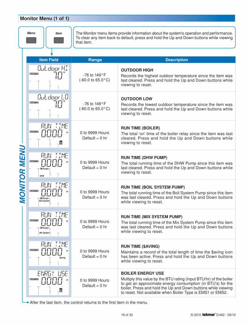
Item Field Range Description
MONITOR -76 to 149°F(-60.0 to 65.0°C)
OUTDOOR HIGHRecords the highest outdoor temperature since the item was last cleared. Press and hold the Up and Down buttons while viewing to reset.
MONITOR -76 to 149°F(-60.0 to 65.0°C)
OUTDOOR LOWRecords the lowest outdoor temperature since the item was last cleared. Press and hold the Up and Down buttons while viewing to reset.
MONITOR hr 0 to 9999 Hours
Default = 0 hr
RUN TIME (BOILER) The total ‘on’ time of the boiler relay since the item was last cleared. Press and hold the Up and Down buttons while viewing to reset.
MONITOR hr
DHW
Pumps
0 to 9999 Hours
Default = 0 hr
RUN TIME (DHW PUMP) The total running time of the DHW Pump since this item was last cleared. Press and hold the Up and Down buttons while viewing to reset.
MONITOR hr
Boil SystemPumps
0 to 9999 Hours
Default = 0 hr
RUN TIME (BOIL SYSTEM PUMP) The total running time of the Boil System Pump since this item was last cleared. Press and hold the Up and Down buttons while viewing to reset.
MONITOR hr
Mix System
Pumps
0 to 9999 Hours
Default = 0 hr
RUN TIME (MIX SYSTEM PUMP)The total running time of the Mix System Pump since this item was last cleared. Press and hold the Up and Down buttons while viewing to reset.
MONITOR hr
Saving
0 to 9999 Hours
Default = 0 hr
RUN TIME ($AVING) Maintains a record of the total length of time the $aving icon has been active. Press and hold the Up and Down buttons while viewing to reset.
MONITOR hr 0 to 9999 Hours
Default = 0 hr
BOILER ENERGY USE Multiply this value by the BTU rating (input BTU/hr) of the boiler to get an approximate energy consumption (in BTU’s) for the boiler. Press and hold the Up and Down buttons while viewing to reset. Not available when Boiler Type is EMS1 or EMS2.
MO
NIT
OR
ME
NU
After the last item, the control returns to the first item in the menu.
The Monitor menu items provide information about the system’s operation and performance. To clear any item back to default, press and hold the Up and Down buttons while viewing that item.
Monitor Menu (1 of 1)
© 2010 D 402 - 09/10 20 of 32
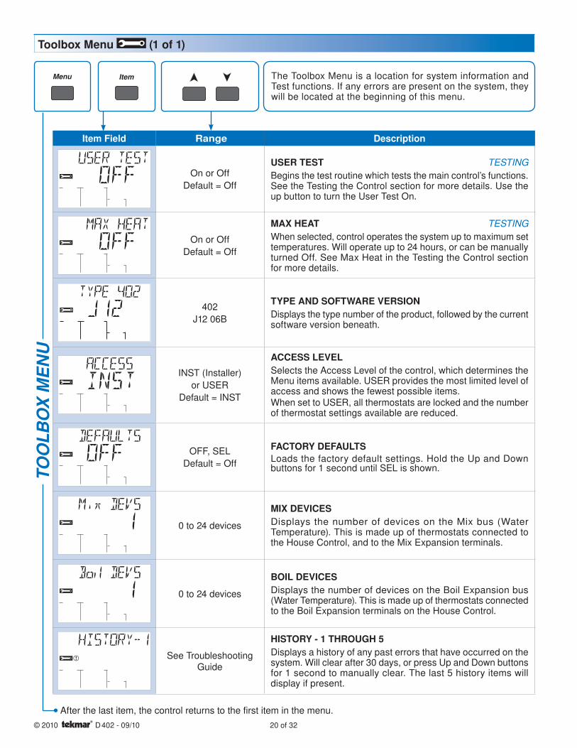
Item Field Range Description
On or Off
Default = Off
USER TEST TESTING
Begins the test routine which tests the main control’s functions. See the Testing the Control section for more details. Use the up button to turn the User Test On.
On or Off
Default = Off
MAX HEAT TESTING
When selected, control operates the system up to maximum set temperatures. Will operate up to 24 hours, or can be manually turned Off. See Max Heat in the Testing the Control section for more details.
402
J12 06B
TYPE AND SOFTWARE VERSIONDisplays the type number of the product, followed by the current software version beneath.
INST (Installer)
or USER
Default = INST
ACCESS LEVELSelects the Access Level of the control, which determines the Menu items available. USER provides the most limited level of access and shows the fewest possible items.When set to USER, all thermostats are locked and the number of thermostat settings available are reduced.
OFF, SEL
Default = Off
FACTORY DEFAULTSLoads the factory default settings. Hold the Up and Down buttons for 1 second until SEL is shown.
0 to 24 devices
MIX DEVICESDisplays the number of devices on the Mix bus (Water Temperature). This is made up of thermostats connected to the House Control, and to the Mix Expansion terminals.
0 to 24 devices
BOIL DEVICESDisplays the number of devices on the Boil Expansion bus (Water Temperature). This is made up of thermostats connected to the Boil Expansion terminals on the House Control.
See Troubleshooting Guide
HISTORY - 1 THROUGH 5Displays a history of any past errors that have occurred on the system. Will clear after 30 days, or press Up and Down buttons for 1 second to manually clear. The last 5 history items will display if present.
TOO
LBO
X M
EN
U
After the last item, the control returns to the first item in the menu.
The Toolbox Menu is a location for system information and Test functions. If any errors are present on the system, they will be located at the beginning of this menu.
Toolbox Menu (1 of 1)
21 of 32 © 2010 D 402 - 09/10
Sequence of Operation tekmarNet® System Section A
tekmarNet® is a family of products that use communication to operate the HVAC system in a comfortable and efficient manner. The House Control is the central component in a tekmarNet® system and requires tekmarNet®2 (tN2) Thermostats to be directly connected to the control.
The tekmarNet®4 (tN4) Expansion terminals can link the House Control with other tekmarNet® components:
Wiring Centers 313, 314, 315, 316 - Add additional zones
tN2 and tN4 Thermostats - Add thermostats
tN4 Timer 033 - Adds 4 programmable schedules
tN4 User Switch 479 - Provides a system override for vacations and holidays
tN4 Setpoint Control 161 - Control hot tubs, pools and more
•
•
•
•
•
Mix Temperature Reset Operation Section B
When an onboard tN2 Thermostat calls for heat, the House Control registers a Mix call for hydronic heating.
When a device connected to the tN4 Mix Expansion terminals calls for heat, the House Control registers a Mix Expansion Call for hydronic heating on the mix loop.
Mix
Calls
Mix Exp
Calls
Mix Call or Mix Expansion Call ----------------------------------------------------------------------- -----------------------------------------------------------------------
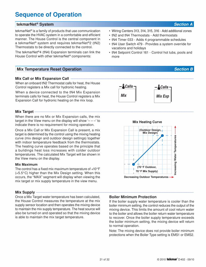
Mix Target -------------------------------------------------------------------------------------------- --------------------------------------------------------------------------------------------
When there are no Mix or Mix Expansion calls, the mix target in the View menu on the display will show ‘– – –’ to indicate there is no requirement for mixing operation.
Once a Mix Call or Mix Expansion Call is present, a mix target is determined by the control using the mixing heating curve (mix design and outdoor design settings) together with indoor temperature feedback from the thermostats. The heating curve operates based on the principle that a buildings heat loss increases with colder outdoor temperatures. The calculated Mix Target will be shown in the View menu on the display.
Mix MaximumThe control has a fixed mix maximum temperature of +10°F (+5.5°C) higher than the Mix Design setting. When this occurs, the “MAX” segment will display when viewing the mix target or mix supply temperature in the view menu.
Mix Heating Curve
(70°F Outdoor,70°F Mix Supply)
Decreasing Outdoor Temperatures In
crea
sing
Wat
er T
empe
ratu
res
(Outdoor Design, Mix Design)
Mix Supply ------------------------------------------------------------------------------------------- -------------------------------------------------------------------------------------------Once a Mix Target water temperature has been calculated, the House Control measures the temperature at the mix supply sensor location and then operates the mixing device to maintain the mix supply temperature. The heat source will also be turned on and operated so that the mixing device is able to maintain the mix target temperature.
Boiler Minimum ProtectionIf the boiler supply water temperature is cooler than the boiler minimum setting, the control reduces the output of the mixing device. This limits the amount of cool return water to the boiler and allows the boiler return water temperature to recover. Once the boiler supply temperature exceeds the boiler minimum setting, the mixing device will return to normal operation.
Note: The mixing device does not provide boiler minimum protections when the Boiler Type setting is EMS1 or EMS2.

© 2010 D 402 - 09/10 22 of 32
Mixing Device Type ----------------------------------------------------------------------------------- -----------------------------------------------------------------------------------
The House Control can operate a mixing device such as a mixing valve or variable speed injection pump based upon one of four output signals. The device output bar graph on the display indicates the approximate position of the mixing device.
Variable Speed Injection PumpA standard wet rotor circulator can be connected to the Variable Speed Pump output on the back of the control. The control varies the circulator speed to maintain the correct mixed supply water temperature at the mix supply sensor. For correct sizing and piping of the variable speed injection circulator, refer to essay E 021. Note: Pumps manufactured with an internal variable speed controller are not compatible with the House Control.
Floating Action 24 V (ac) A 24 V (ac) floating action actuator motor and mixing valve can be connected to the Floating Action outputs on the front of the House Control. The control pulses the actuator motor open or closed to maintain the correct supply water temperature at the mix supply sensor when there is a requirement for mixing.
Modulating 0-10 V (dc)*Only available if a one or two stage on-off boiler is used.
A modulating 0-10 V (dc) actuating motor can be used to operate the mixing valve. The control uses the Mod dc/mA output to provide an analog 0-10 V (dc) signal to the actuator in order to maintain the correct mix supply temperature.
Modulating 4-20 mA*Only available if a one or two stage on-off boiler is used.
A modulating 4-20 mA actuating motor can be used to operate the mixing valve. The control uses the Mod dc/mA output to provide an analog 4-20 mA signal to the actuator in order to maintain the correct mix supply temperature.
Mixing Device ExercisingThe control operates the mixing device from 0 to 100% output every 3 days to help prevent corrosion and / or precipitate build up on the mixing valve or pump that could lead to seizure of the mixing device. The control ensures that no heat is supplied to the zones during exercising.
Boiler Temperature Reset Operation Section C
Boiler Expansion Call -------------------------------------------------------------------------------- --------------------------------------------------------------------------------
Boil ExpCallsWhen a device connected to the tN4 Boil Expansion
terminals calls for heat, the House Control registers a Boil Expansion call for hydronic heating on the boiler loop.
Boiler Target ----------------------------------------------------------------------------------------- -----------------------------------------------------------------------------------------When there are no Boiler Expansion or Mix calls, the boiler target in the View menu on the display will show ‘– – –’ to indicate there is no requirement for boiler operation.
Once a Boiler Expansion Call is present, a boiler target is determined by the control using the boiler heating curve (boiler minimum, boiler design and outdoor design settings) together with indoor temperature feedback from the thermostats. The heating curve operates based on the principle that a buildings heat loss increases with colder outdoor temperatures. The calculated Boiler Target will be shown in the View menu on the display.
When a Mix or Mix Expansion Call is present, the control calculates a boiler target that is higher than the mix target using Boiler Load Reset.
Boiler MinimumThe House Control protects non-condensing boilers from sustained flue gas condensation and thermal shock through the Boiler Minimum setting. The boiler minimum is the lowest temperature that the control is allowed to use as a boiler target temperature. If the boiler is operating at the boiler minimum temperature, the “MIN” segment is turned on in the display when viewing either the boiler supply temperature or the boiler target temperature.
Boiler Heating Curve
(70°F Outdoor,Boiler Minimum)
Decreasing Outdoor Temperatures
Incr
easi
ng W
ater
Tem
pera
ture
s
(Outdoor Design, Boiler Design)
Boiler MaximumThe control has a fixed boiler maximum temperature of + 10°F (+5.5°C) higher than the Boiler Design setting for the Boiler Heating Curve. When this occurs, the “MAX” segment will display when viewing the boiler target or boiler supply temperature in the view menu. The control will operate the boiler so that the boiler supply temperature will never exceed 210°F (99.0°C).
23 of 32 © 2010 D 402 - 09/10
Domestic Hot Water Tank Operation Section D
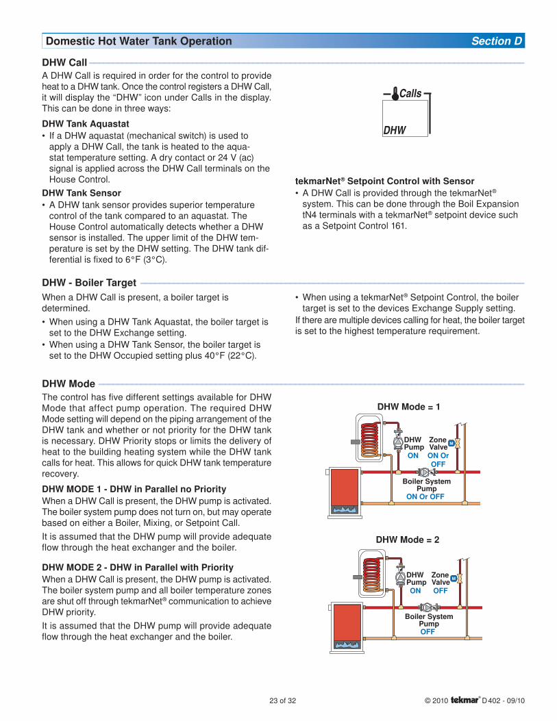
A DHW Call is required in order for the control to provide heat to a DHW tank. Once the control registers a DHW Call, it will display the “DHW” icon under Calls in the display. This can be done in three ways:
DHW Tank AquastatIf a DHW aquastat (mechanical switch) is used to apply a DHW Call, the tank is heated to the aqua-stat temperature setting. A dry contact or 24 V (ac) signal is applied across the DHW Call terminals on the House Control.
DHW Tank SensorA DHW tank sensor provides superior temperature control of the tank compared to an aquastat. The House Control automatically detects whether a DHW sensor is installed. The upper limit of the DHW tem-perature is set by the DHW setting. The DHW tank dif-ferential is fixed to 6°F (3°C).
•
•
DHW
Calls
DHW Call --------------------------------------------------------------------------------------------- ---------------------------------------------------------------------------------------------
DHW Mode ------------------------------------------------------------------------------------------- -------------------------------------------------------------------------------------------
The control has five different settings available for DHW Mode that affect pump operation. The required DHW Mode setting will depend on the piping arrangement of the DHW tank and whether or not priority for the DHW tank is necessary. DHW Priority stops or limits the delivery of heat to the building heating system while the DHW tank calls for heat. This allows for quick DHW tank temperature recovery.
DHW MODE 1 - DHW in Parallel no PriorityWhen a DHW Call is present, the DHW pump is activated. The boiler system pump does not turn on, but may operate based on either a Boiler, Mixing, or Setpoint Call.
It is assumed that the DHW pump will provide adequate flow through the heat exchanger and the boiler.
DHW MODE 2 - DHW in Parallel with PriorityWhen a DHW Call is present, the DHW pump is activated. The boiler system pump and all boiler temperature zones are shut off through tekmarNet® communication to achieve DHW priority.
It is assumed that the DHW pump will provide adequate flow through the heat exchanger and the boiler.
DHW - Boiler Target ---------------------------------------------------------------------------------- ----------------------------------------------------------------------------------
When a DHW Call is present, a boiler target is determined.
When using a DHW Tank Aquastat, the boiler target is set to the DHW Exchange setting.
When using a DHW Tank Sensor, the boiler target is set to the DHW Occupied setting plus 40°F (22°C).
•
•
ON Or OFF
ON
DHWPump
ON OrOFF
ZoneValve
Boiler SystemPump
DHW Mode = 1
OFF
ON
DHWPump
OFF
ZoneValve
Boiler SystemPump
DHW Mode = 2
When using a tekmarNet® Setpoint Control, the boiler target is set to the devices Exchange Supply setting.
If there are multiple devices calling for heat, the boiler target is set to the highest temperature requirement.
•
tekmarNet® Setpoint Control with SensorA DHW Call is provided through the tekmarNet® system. This can be done through the Boil Expansion tN4 terminals with a tekmarNet® setpoint device such as a Setpoint Control 161.
•
© 2010 D 402 - 09/10 24 of 32
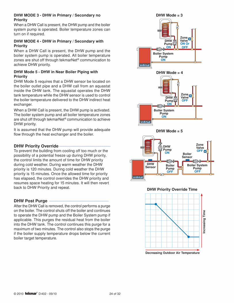
DHW MODE 3 - DHW in Primary / Secondary no PriorityWhen a DHW Call is present, the DHW pump and the boiler system pump is operated. Boiler temperature zones can turn on if required.
DHW MODE 4 - DHW in Primary / Secondary with PriorityWhen a DHW Call is present, the DHW pump and the boiler system pump is operated. All boiler temperature zones are shut off through tekmarNet® communication to achieve DHW priority.
DHW Mode 5 - DHW in Near Boiler Piping with PriorityDHW Mode 5 requires that a DHW sensor be located on the boiler outlet pipe and a DHW call from an aquastat inside the DHW tank. The aquastat operates the DHW tank temperature while the DHW sensor is used to control the boiler temperature delivered to the DHW indirect heat exchanger.
When a DHW Call is present, the DHW pump is activated. The boiler system pump and all boiler temperature zones are shut off through tekmarNet® communication to achieve DHW priority.
It is assumed that the DHW pump will provide adequate flow through the heat exchanger and the boiler.
DHW Priority Override -------------------------- --------------------------To prevent the building from cooling off too much or the possibility of a potential freeze up during DHW priority, the control limits the amount of time for DHW priority during cold weather. During warm weather the DHW priority is 120 minutes. During cold weather the DHW priority is 15 minutes. Once the allowed time for priority has elapsed, the control overrides the DHW priority and resumes space heating for 15 minutes. It will then revert back to DHW Priority and repeat.
DHW Post Purge ------------------------------ ------------------------------After the DHW Call is removed, the control performs a purge on the boiler. The control shuts off the boiler and continues to operate the DHW pump and the Boiler System pump if applicable. This purges the residual heat from the boiler into the DHW tank. The control continues this purge for a maximum of two minutes. The control also stops the purge if the boiler supply temperature drops below the current boiler target temperature.
Boiler SystemPump
DHWPump
ZoneValve
ON
ONON OrOFF
DHW Mode = 3
Boiler SystemPump
DHWPump
ZoneValve
ON
ONOFF
DHW Mode = 4
OFF OFF
DHWSensor
ON
DHWPump OFF
ZoneValve
Boiler SystemPump
BoilerPump
BoilerSensor
DHW Mode = 5
DHW Priority Override Time
Incr
easi
ng T
ime
Decreasing Outdoor Air Temperature
25 of 32 © 2010 D 402 - 09/10
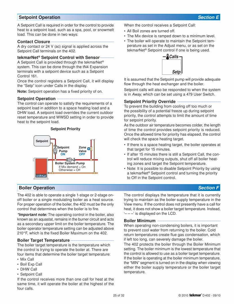
Setpoint Operation Section E
A Setpoint Call is required in order for the control to provide heat to a setpoint load, such as a spa, pool, or snowmelt load. This can be done in two ways:
Contact Closure -------------------------------- --------------------------------A dry contact or 24 V (ac) signal is applied across the Setpoint Call terminals on the 402.
tekmarNet® Setpoint Control with Sensor ------- -------A Setpoint Call is provided through the tekmarNet® system. This can be done through the tN4 Expansion terminals with a setpoint device such as a Setpoint Control 161.
Once the control registers a Setpoint Call, it will display the “Setp” icon under Calls in the display.
Note: Setpoint operation has a fixed priority of on.
Setpoint Operation ----------------------------- -----------------------------The control can operate to satisfy the requirements of a setpoint load in addition to a space heating load and a DHW load. A setpoint load overrides the current outdoor reset temperature and WWSD setting in order to provide heat to the setpoint load.
Setpoint Priority
Boiler System PumpIf Mix demand = OnOtherwise = Off
SetpointPump
Setpoint
ON
ZoneValveOFF
When the control receives a Setpoint Call:
All Boil zones are turned off.
The Mix device is ramped down to a minimum level.
The boiler will operate to maintain the Setpoint tem-perature as set in the Adjust menu, or as set on the tekmarNet® Setpoint control if one is being used.
Setp
Calls
It is assumed that the Setpoint pump will provide adequate flow through the heat exchanger and the boiler.
Setpoint calls will also be responded to when the system is in Away, which can be set using a 479 User Switch.
Setpoint Priority Override ---------------------- ----------------------To prevent the building from cooling off too much or the possibility of a potential freeze up during setpoint priority, the control attempts to limit the amount of time for setpoint priority.
As the outdoor air temperature becomes colder, the length of time the control provides setpoint priority is reduced. Once the allowed time for priority has elapsed, the control will check the space heating target.
If there is a space heating target, the boiler operates at that target for 15 minutes.
If after 15 minutes there is still a Setpoint Call, the con-trol will reduce mixing outputs, shut off all boiler heat-ing zones and target the Setpoint temperature.
Note: It is possible to disable Setpoint Priority by using a tekmarNet® Setpoint control and turning the priority to Off in the Setpoint control.
•
•
•
•
•
•
Boiler Operation Section FThe 402 is able to operate a single 1-stage or 2-stage on-off boiler or a single modulating boiler as a heat source. For proper operation of the boiler, the 402 must be the only control that determines when the boiler is to fire.
*Important note: The operating control in the boiler, also known as an aquastat, remains in the burner circuit and acts as a secondary upper limit on the boiler temperature. The boiler operator temperature setting can be adjusted above 210°F, which is the fixed Boiler Maximum on the 402.
Boiler Target Temperature ---------------------- ----------------------The boiler target temperature is the temperature which the control is trying to operate the boiler at. There are four items that determine the boiler target temperature:
Mix Call
Boil Exp Call
DHW Call
Setpoint Call
If the control receives more than one call for heat at the same time, it will operate the boiler at the highest of the four calls.
•
•
•
•
The control displays the temperature that it is currently trying to maintain as the boiler supply temperature in the View menu. If the control does not presently have a call for heat, it does not show a boiler target temperature. Instead, ‘– – –’ is displayed on the LCD.
Boiler Minimum -------------------------------- --------------------------------When operating non-condensing boilers, it is important to prevent cool water from returning to the boiler. Cold return temperatures create flue gas condensation, which if left too long, can severely damage the boiler.
The 402 protects the boiler through the Boiler Minimum setting. The boiler minimum is the lowest temperature that the control is allowed to use as a boiler target temperature. If the boiler is operating at the boiler minimum temperature, the “MIN” segment is turned on in the display when viewing either the boiler supply temperature or the boiler target temperature.
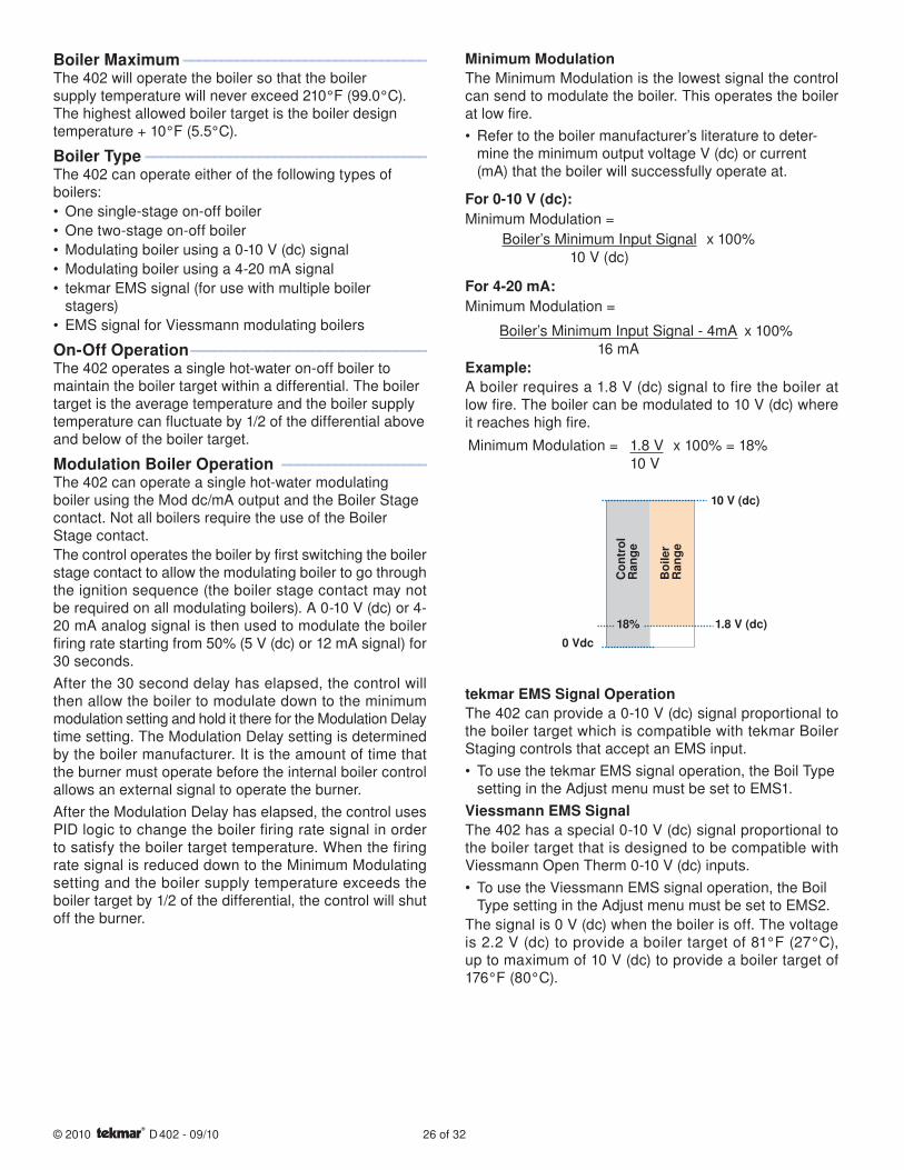
© 2010 D 402 - 09/10 26 of 32
Boiler Maximum -------------------------------- --------------------------------The 402 will operate the boiler so that the boiler supply temperature will never exceed 210°F (99.0°C). The highest allowed boiler target is the boiler design temperature + 10°F (5.5°C).
Boiler Type ------------------------------------- -------------------------------------The 402 can operate either of the following types of boilers:
One single-stage on-off boiler
One two-stage on-off boiler
Modulating boiler using a 0-10 V (dc) signal
Modulating boiler using a 4-20 mA signal
tekmar EMS signal (for use with multiple boiler stagers)
EMS signal for Viessmann modulating boilers
On-Off Operation ------------------------------- -------------------------------The 402 operates a single hot-water on-off boiler to maintain the boiler target within a differential. The boiler target is the average temperature and the boiler supply temperature can fluctuate by 1/2 of the differential above and below of the boiler target.
Modulation Boiler Operation ------------------- -------------------The 402 can operate a single hot-water modulating boiler using the Mod dc/mA output and the Boiler Stage contact. Not all boilers require the use of the Boiler Stage contact.
The control operates the boiler by first switching the boiler stage contact to allow the modulating boiler to go through the ignition sequence (the boiler stage contact may not be required on all modulating boilers). A 0-10 V (dc) or 4-20 mA analog signal is then used to modulate the boiler firing rate starting from 50% (5 V (dc) or 12 mA signal) for 30 seconds.
After the 30 second delay has elapsed, the control will then allow the boiler to modulate down to the minimum modulation setting and hold it there for the Modulation Delay time setting. The Modulation Delay setting is determined by the boiler manufacturer. It is the amount of time that the burner must operate before the internal boiler control allows an external signal to operate the burner.
After the Modulation Delay has elapsed, the control uses PID logic to change the boiler firing rate signal in order to satisfy the boiler target temperature. When the firing rate signal is reduced down to the Minimum Modulating setting and the boiler supply temperature exceeds the boiler target by 1/2 of the differential, the control will shut off the burner.
•
•
•
•
•
•
Minimum ModulationThe Minimum Modulation is the lowest signal the control can send to modulate the boiler. This operates the boiler at low fire.
Refer to the boiler manufacturer’s literature to deter-mine the minimum output voltage V (dc) or current (mA) that the boiler will successfully operate at.
For 0-10 V (dc):Minimum Modulation =
Boiler’s Minimum Input Signal x 100%10 V (dc)
For 4-20 mA:Minimum Modulation =
Boiler’s Minimum Input Signal - 4mA x 100%16 mA
Example:A boiler requires a 1.8 V (dc) signal to fire the boiler at low fire. The boiler can be modulated to 10 V (dc) where it reaches high fire.
Minimum Modulation = 1.8 V x 100% = 18%10 V
1.8 V (dc)
10 V (dc)
Co
ntr
ol
Ran
ge
Bo
iler
Ran
ge
0 Vdc
18%
tekmar EMS Signal OperationThe 402 can provide a 0-10 V (dc) signal proportional to the boiler target which is compatible with tekmar Boiler Staging controls that accept an EMS input.
To use the tekmar EMS signal operation, the Boil Type setting in the Adjust menu must be set to EMS1.
Viessmann EMS SignalThe 402 has a special 0-10 V (dc) signal proportional to the boiler target that is designed to be compatible with Viessmann Open Therm 0-10 V (dc) inputs.
To use the Viessmann EMS signal operation, the Boil Type setting in the Adjust menu must be set to EMS2.
The signal is 0 V (dc) when the boiler is off. The voltage is 2.2 V (dc) to provide a boiler target of 81°F (27°C), up to maximum of 10 V (dc) to provide a boiler target of 176°F (80°C).
•
•
•
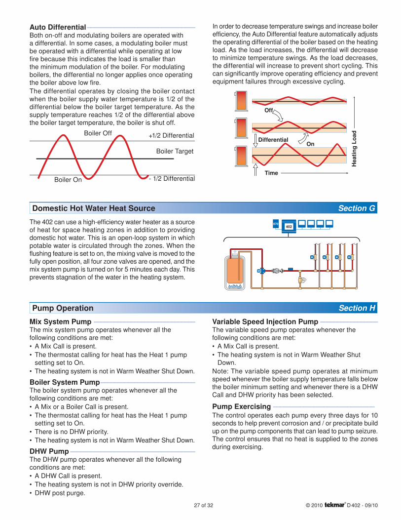
27 of 32 © 2010 D 402 - 09/10
Auto Differential -------------------------------- --------------------------------Both on-off and modulating boilers are operated with a differential. In some cases, a modulating boiler must be operated with a differential while operating at low fire because this indicates the load is smaller than the minimum modulation of the boiler. For modulating boilers, the differential no longer applies once operating the boiler above low fire.
The differential operates by closing the boiler contact when the boiler supply water temperature is 1/2 of the differential below the boiler target temperature. As the supply temperature reaches 1/2 of the differential above the boiler target temperature, the boiler is shut off.
+1/2 Differential
- 1/2 Differential
Boiler Target
Boiler On
Boiler Off
In order to decrease temperature swings and increase boiler efficiency, the Auto Differential feature automatically adjusts the operating differential of the boiler based on the heating load. As the load increases, the differential will decrease to minimize temperature swings. As the load decreases, the differential will increase to prevent short cycling. This can significantly improve operating efficiency and prevent equipment failures through excessive cycling.
Off
Differential
Time
Hea
tin
g L
oad
On
Domestic Hot Water Heat Source Section G
The 402 can use a high-efficiency water heater as a source of heat for space heating zones in addition to providing domestic hot water. This is an open-loop system in which potable water is circulated through the zones. When the flushing feature is set to on, the mixing valve is moved to the fully open position, all four zone valves are opened, and the mix system pump is turned on for 5 minutes each day. This prevents stagnation of the water in the heating system.
402070
Pump Operation Section H
Mix System Pump ------------------------------ ------------------------------The mix system pump operates whenever all the following conditions are met:
A Mix Call is present.
The thermostat calling for heat has the Heat 1 pump setting set to On.
The heating system is not in Warm Weather Shut Down.
Boiler System Pump ---------------------------- ----------------------------The boiler system pump operates whenever all the following conditions are met:
A Mix or a Boiler Call is present.
The thermostat calling for heat has the Heat 1 pump setting set to On.
There is no DHW priority.
The heating system is not in Warm Weather Shut Down.
DHW Pump ------------------------------------- -------------------------------------The DHW pump operates whenever all the following conditions are met:
A DHW Call is present.
The heating system is not in DHW priority override.
DHW post purge.
•
•
•
•
•
•
•
•
•
•
Variable Speed Injection Pump ----------------- -----------------The variable speed pump operates whenever the following conditions are met:
A Mix Call is present.
The heating system is not in Warm Weather Shut Down.
Note: The variable speed pump operates at minimum speed whenever the boiler supply temperature falls below the boiler minimum setting and whenever there is a DHW Call and DHW priority has been selected.
Pump Exercising ------------------------------ ------------------------------The control operates each pump every three days for 10 seconds to help prevent corrosion and / or precipitate build up on the pump components that can lead to pump seizure. The control ensures that no heat is supplied to the zones during exercising.
•
•

© 2010 D 402 - 09/10 28 of 32
The “$aving” icon is displayed when energy is being saved. The following features reduce energy consumption.
Network Schedules--------------------------------------------------------Adding a schedule to a tekmarNet® system is both easy and valuable. A Timer 033 provides scheduling with up to 4 events per day for every tekmarNet® Thermostat. Turning down the room temperatures when they are unoccupied reduces boiler on-time and energy consumption which helps save money and the environment.
One-Touch Economy -------------------------- --------------------------A User Switch 479 allows for one-touch overrides of the system. For example, if leaving the building for vacation, simply press the “Away” button and all the thermostats will immediately operate at a lower temperature, instead of having to walk around the building lowering the heating temperature setting and raising the cooling temperature setting on each thermostat.
DHW Tank During Away ----------------------- -----------------------In addition to the One-Touch setback, a User Switch 479 also allows the user to press the ‘Away’ button and tell the House Control 402 to ignore DHW Calls, preventing the DHW tank from unnecessarily heating up when no one is living in the building.
Warm Weather Shut Down (WWSD) ------------ ------------During warmer weather, heating of the rooms is typically no longer required. To prevent energy waste from unnecessary boiler operation, the control goes into Warm Weather Shut Down (WWSD) when the outdoor temperature rises above the WWSD temperature set in the Adjust menu.
Energy Saving Features Section I
Further Savings!Use a Timer 033 with programmable schedule #1 to gain the WWSD Unoccupied setting. This provides an additional WWSD temperature that can be set even lower for Unoccupied and Sleep time periods.
This setting will appear after WWSD in the Adjust menu if a Timer 033 or User Switch is present on the system.
Zone Synchronization ------------------------- -------------------------Another feature of the House Control is Zone Synchronization. In typical zoned systems, the thermostats operate on a stand-alone basis. This means that a zone turns on and off as required without any regard for other zones. The net effect is random operation of the zones causing short cycling of the heat source. tekmarNet® thermostats communicate to ensure that their cycles are synchronized. Energy is saved by ensuring zones requiring heat operate on the same cycle, therefore reducing short cycling of the boiler.
Zone Post Purge ------------------------------ ------------------------------When the last zone is nearly satisfied for heating, the boiler is shut off and the zone continues to operate together with the boiler system pump and / or mix system pump. This purges the residual heat from the boiler into this zone. The control continues this purge for a maximum of two minutes. The control will stop the purge if the boiler supply temperature drops below the boiler minimum setting.
•
TroubleshootingIt is recommended to complete all wiring to ensure trouble free operation. Should an error occur, simply follow these steps:
1. Find: If the House Control or tekmarNet® Thermostat flashes on the screen, it is indicating a problem on the system.
2. Identify: Use the Menu button to locate the Toolbox Menu. The Error code should appear as the first item.
3. Solve: Using the lookup chart below, match the Error code to the one on the control. Use the Description in the chart to solve the problem.
Error Messages (1 of 3)
Error Message Description
ADJUST ERRORThe control failed to read the Adjust menu settings, and reloaded the factory default settings. Operation stops until all the Adjust menu settings are checked.
Note: To clear the error, the access level must be set to Installer and each setting in the Adjust menu must be checked.
OUTDOOR SENSOR SHORT CIRCUITDue to a short circuit, the control failed to read the outdoor sensor. As a result, the control assumes an outdoor temperature of 32°F (0°C) and continues operation. Locate and repair the problem as described in the “Test the Sensor Wiring” section.
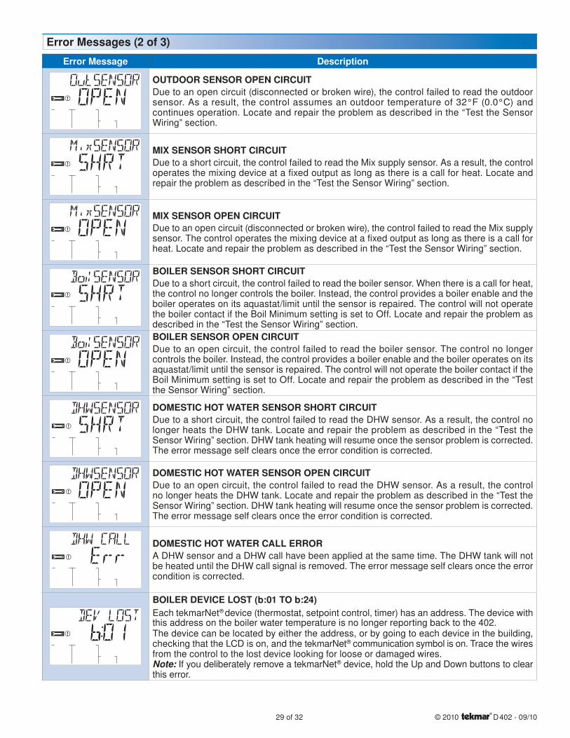
29 of 32 © 2010 D 402 - 09/10
Error Message Description
OUTDOOR SENSOR OPEN CIRCUITDue to an open circuit (disconnected or broken wire), the control failed to read the outdoor sensor. As a result, the control assumes an outdoor temperature of 32°F (0.0°C) and continues operation. Locate and repair the problem as described in the “Test the Sensor Wiring” section.
MIX SENSOR SHORT CIRCUITDue to a short circuit, the control failed to read the Mix supply sensor. As a result, the control operates the mixing device at a fixed output as long as there is a call for heat. Locate and repair the problem as described in the “Test the Sensor Wiring” section.
MIX SENSOR OPEN CIRCUITDue to an open circuit (disconnected or broken wire), the control failed to read the Mix supply sensor. The control operates the mixing device at a fixed output as long as there is a call for heat. Locate and repair the problem as described in the “Test the Sensor Wiring” section.
BOILER SENSOR SHORT CIRCUITDue to a short circuit, the control failed to read the boiler sensor. When there is a call for heat, the control no longer controls the boiler. Instead, the control provides a boiler enable and the boiler operates on its aquastat/limit until the sensor is repaired. The control will not operate the boiler contact if the Boil Minimum setting is set to Off. Locate and repair the problem as described in the “Test the Sensor Wiring” section.
BOILER SENSOR OPEN CIRCUITDue to an open circuit, the control failed to read the boiler sensor. The control no longer controls the boiler. Instead, the control provides a boiler enable and the boiler operates on its aquastat/limit until the sensor is repaired. The control will not operate the boiler contact if the Boil Minimum setting is set to Off. Locate and repair the problem as described in the “Test the Sensor Wiring” section.
DOMESTIC HOT WATER SENSOR SHORT CIRCUITDue to a short circuit, the control failed to read the DHW sensor. As a result, the control no longer heats the DHW tank. Locate and repair the problem as described in the “Test the Sensor Wiring” section. DHW tank heating will resume once the sensor problem is corrected. The error message self clears once the error condition is corrected.
DOMESTIC HOT WATER SENSOR OPEN CIRCUITDue to an open circuit, the control failed to read the DHW sensor. As a result, the control no longer heats the DHW tank. Locate and repair the problem as described in the “Test the Sensor Wiring” section. DHW tank heating will resume once the sensor problem is corrected. The error message self clears once the error condition is corrected.
DOMESTIC HOT WATER CALL ERRORA DHW sensor and a DHW call have been applied at the same time. The DHW tank will not be heated until the DHW call signal is removed. The error message self clears once the error condition is corrected.
BOILER DEVICE LOST (b:01 TO b:24)Each tekmarNet® device (thermostat, setpoint control, timer) has an address. The device with this address on the boiler water temperature is no longer reporting back to the 402.The device can be located by either the address, or by going to each device in the building, checking that the LCD is on, and the tekmarNet® communication symbol is on. Trace the wires from the control to the lost device looking for loose or damaged wires.Note: If you deliberately remove a tekmarNet® device, hold the Up and Down buttons to clear this error.
Error Messages (2 of 3)
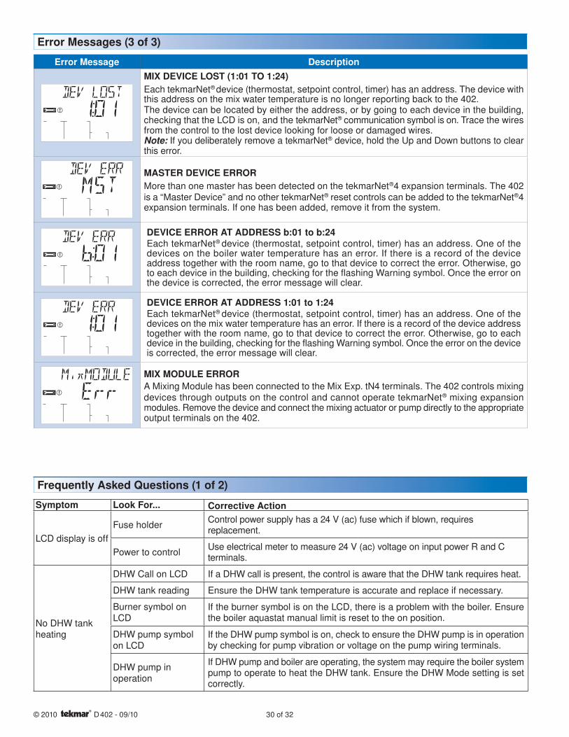
© 2010 D 402 - 09/10 30 of 32
Error Messages (3 of 3)
Error Message DescriptionMIX DEVICE LOST (1:01 TO 1:24)Each tekmarNet® device (thermostat, setpoint control, timer) has an address. The device with this address on the mix water temperature is no longer reporting back to the 402.The device can be located by either the address, or by going to each device in the building, checking that the LCD is on, and the tekmarNet® communication symbol is on. Trace the wires from the control to the lost device looking for loose or damaged wires.Note: If you deliberately remove a tekmarNet® device, hold the Up and Down buttons to clear this error.
MASTER DEVICE ERRORMore than one master has been detected on the tekmarNet®4 expansion terminals. The 402 is a “Master Device” and no other tekmarNet® reset controls can be added to the tekmarNet®4 expansion terminals. If one has been added, remove it from the system.
DEVICE ERROR AT ADDRESS b:01 to b:24Each tekmarNet® device (thermostat, setpoint control, timer) has an address. One of the devices on the boiler water temperature has an error. If there is a record of the device address together with the room name, go to that device to correct the error. Otherwise, go to each device in the building, checking for the flashing Warning symbol. Once the error on the device is corrected, the error message will clear.
DEVICE ERROR AT ADDRESS 1:01 to 1:24Each tekmarNet® device (thermostat, setpoint control, timer) has an address. One of the devices on the mix water temperature has an error. If there is a record of the device address together with the room name, go to that device to correct the error. Otherwise, go to each device in the building, checking for the flashing Warning symbol. Once the error on the device is corrected, the error message will clear.
MIX MODULE ERRORA Mixing Module has been connected to the Mix Exp. tN4 terminals. The 402 controls mixing devices through outputs on the control and cannot operate tekmarNet® mixing expansion modules. Remove the device and connect the mixing actuator or pump directly to the appropriate output terminals on the 402.
Symptom Look For... Corrective Action
LCD display is off
Fuse holderControl power supply has a 24 V (ac) fuse which if blown, requires replacement.
Power to controlUse electrical meter to measure 24 V (ac) voltage on input power R and C terminals.
No DHW tank heating
DHW Call on LCD If a DHW call is present, the control is aware that the DHW tank requires heat.
DHW tank reading Ensure the DHW tank temperature is accurate and replace if necessary.
Burner symbol on LCD
If the burner symbol is on the LCD, there is a problem with the boiler. Ensure the boiler aquastat manual limit is reset to the on position.
DHW pump symbol on LCD
If the DHW pump symbol is on, check to ensure the DHW pump is in operation by checking for pump vibration or voltage on the pump wiring terminals.
DHW pump in operation
If DHW pump and boiler are operating, the system may require the boiler system pump to operate to heat the DHW tank. Ensure the DHW Mode setting is set correctly.
Frequently Asked Questions (1 of 2)
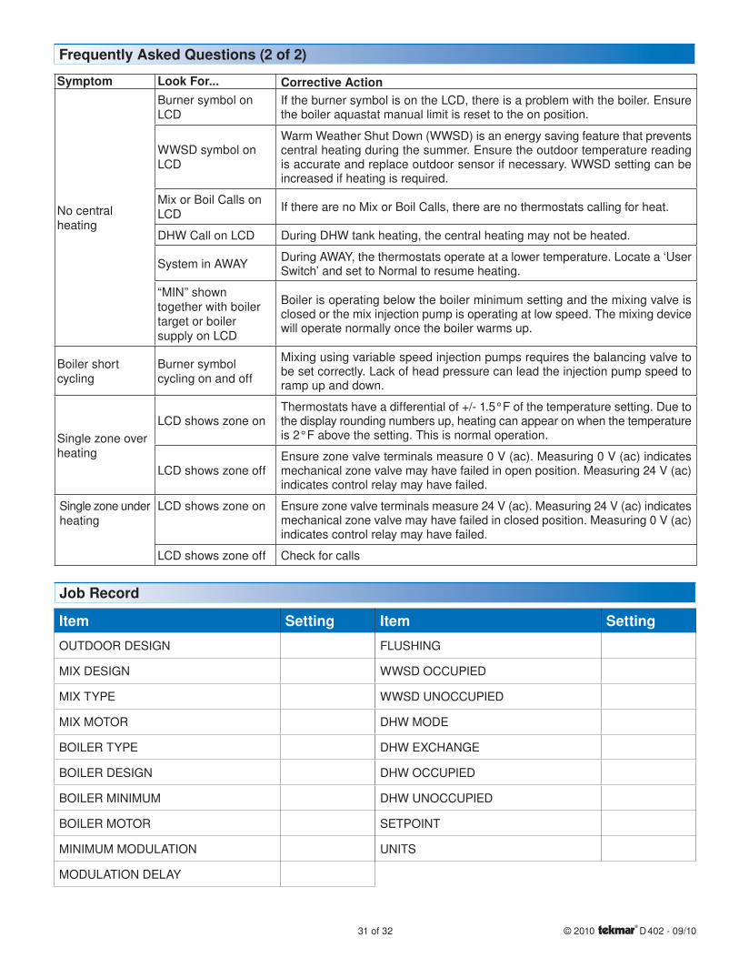
31 of 32 © 2010 D 402 - 09/10
Symptom Look For... Corrective Action
No central heating
Burner symbol on LCD
If the burner symbol is on the LCD, there is a problem with the boiler. Ensure the boiler aquastat manual limit is reset to the on position.
WWSD symbol on LCD
Warm Weather Shut Down (WWSD) is an energy saving feature that prevents central heating during the summer. Ensure the outdoor temperature reading is accurate and replace outdoor sensor if necessary. WWSD setting can be increased if heating is required.
Mix or Boil Calls on LCD
If there are no Mix or Boil Calls, there are no thermostats calling for heat.
DHW Call on LCD During DHW tank heating, the central heating may not be heated.
System in AWAYDuring AWAY, the thermostats operate at a lower temperature. Locate a ‘User Switch’ and set to Normal to resume heating.
“MIN” shown together with boiler target or boiler supply on LCD
Boiler is operating below the boiler minimum setting and the mixing valve is closed or the mix injection pump is operating at low speed. The mixing device will operate normally once the boiler warms up.
Boiler short cycling
Burner symbol cycling on and off
Mixing using variable speed injection pumps requires the balancing valve to be set correctly. Lack of head pressure can lead the injection pump speed to ramp up and down.
Single zone over heating
LCD shows zone onThermostats have a differential of +/- 1.5°F of the temperature setting. Due to the display rounding numbers up, heating can appear on when the temperature is 2°F above the setting. This is normal operation.
LCD shows zone offEnsure zone valve terminals measure 0 V (ac). Measuring 0 V (ac) indicates mechanical zone valve may have failed in open position. Measuring 24 V (ac) indicates control relay may have failed.
Single zone under heating
LCD shows zone on Ensure zone valve terminals measure 24 V (ac). Measuring 24 V (ac) indicates mechanical zone valve may have failed in closed position. Measuring 0 V (ac) indicates control relay may have failed.
LCD shows zone off Check for calls
Frequently Asked Questions (2 of 2)
Item Setting
OUTDOOR DESIGN
MIX DESIGN
MIX TYPE
MIX MOTOR
BOILER TYPE
BOILER DESIGN
BOILER MINIMUM
BOILER MOTOR
MINIMUM MODULATION
MODULATION DELAY
Item Setting
FLUSHING
WWSD OCCUPIED
WWSD UNOCCUPIED
DHW MODE
DHW EXCHANGE
DHW OCCUPIED
DHW UNOCCUPIED
SETPOINT
UNITS
Job Record
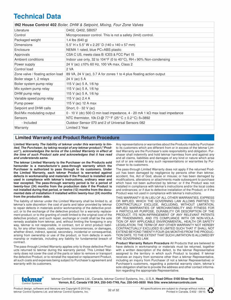
Product design, software and literature are Copyright © 2010 by:tekmar Control Systems Ltd. and tekmar Control Systems, Inc.
32 of 32All specifications are subject to change without notice.
Printed in Canada. D 402 - 09/10.
tekmar Control Systems Ltd., Canada, tekmar Control Systems, Inc., U.S.A. Head Offi ce: 5100 Silver Star Road, Vernon, B.C. Canada V1B 3K4, 250-545-7749, Fax. 250-545-0650 Web Site: www.tekmarcontrols.com
Limited Warranty The liability of tekmar under this warranty is lim-ited. The Purchaser, by taking receipt of any tekmar product (“Prod-uct”), acknowledges the terms of the Limited Warranty in effect at the time of such Product sale and acknowledges that it has read and understands same.The tekmar Limited Warranty to the Purchaser on the Products sold hereunder is a manufacturer’s pass-through warranty which the Purchaser is authorized to pass through to its customers. Under the Limited Warranty, each tekmar Product is warranted against defects in workmanship and materials if the Product is installed and used in compliance with tekmar’s instructions, ordinary wear and tear excepted. The pass-through warranty period is for a period of twenty-four (24) months from the production date if the Product is not installed during that period, or twelve (12) months from the docu-mented date of installation if installed within twenty-four (24) months from the production date.The liability of tekmar under the Limited Warranty shall be limited to, at tekmar’s sole discretion: the cost of parts and labor provided by tekmar to repair defects in materials and/or workmanship of the defective prod-uct; or to the exchange of the defective product for a warranty replace-ment product; or to the granting of credit limited to the original cost of the defective product, and such repair, exchange or credit shall be the sole remedy available from tekmar, and, without limiting the foregoing in any way, tekmar is not responsible, in contract, tort or strict product liabil-ity, for any other losses, costs, expenses, inconveniences, or damages, whether direct, indirect, special, secondary, incidental or consequential, arising from ownership or use of the product, or from defects in work-manship or materials, including any liability for fundamental breach of contract.
The pass-through Limited Warranty applies only to those defective Prod-ucts returned to tekmar during the warranty period. This Limited War-ranty does not cover the cost of the parts or labor to remove or transport the defective Product, or to reinstall the repaired or replacement Product, all such costs and expenses being subject to Purchaser’s agreement and warranty with its customers.
Any representations or warranties about the Products made by Purchaser to its customers which are different from or in excess of the tekmar Lim-ited Warranty are the Purchaser’s sole responsibility and obligation. Pur-chaser shall indemnify and hold tekmar harmless from and against any and all claims, liabilities and damages of any kind or nature which arise out of or are related to any such representations or warranties by Pur-chaser to its customers.
The pass-through Limited Warranty does not apply if the returned Prod-uct has been damaged by negligence by persons other than tekmar, accident, fire, Act of God, abuse or misuse; or has been damaged by modifications, alterations or attachments made subsequent to purchase which have not been authorized by tekmar; or if the Product was not installed in compliance with tekmar’s instructions and/or the local codes and ordinances; or if due to defective installation of the Product; or if the Product was not used in compliance with tekmar’s instructions.
THIS WARRANTY IS IN LIEU OF ALL OTHER WARRANTIES, EXPRESS OR IMPLIED, WHICH THE GOVERNING LAW ALLOWS PARTIES TO CONTRACTUALLY EXCLUDE, INCLUDING, WITHOUT LIMITATION, IMPLIED WARRANTIES OF MERCHANTABILITY AND FITNESS FOR A PARTICULAR PURPOSE, DURABILITY OR DESCRIPTION OF THE PRODUCT, ITS NON-INFRINGEMENT OF ANY RELEVANT PATENTS OR TRADEMARKS, AND ITS COMPLIANCE WITH OR NON-VIOLA-TION OF ANY APPLICABLE ENVIRONMENTAL, HEALTH OR SAFETY LEGISLATION; THE TERM OF ANY OTHER WARRANTY NOT HEREBY CONTRACTUALLY EXCLUDED IS LIMITED SUCH THAT IT SHALL NOT EXTEND BEYOND TWENTY-FOUR (24) MONTHS FROM THE PRODUC-TION DATE, TO THE EXTENT THAT SUCH LIMITATION IS ALLOWED BY THE GOVERNING LAW.
Product Warranty Return Procedure All Products that are believed to have defects in workmanship or materials must be returned, together with a written description of the defect, to the tekmar Representative assigned to the territory in which such Product is located. If tekmar receives an inquiry from someone other than a tekmar Representative, including an inquiry from Purchaser (if not a tekmar Representative) or Purchaser’s customers, regarding a potential warranty claim, tekmar’s sole obligation shall be to provide the address and other contact informa-tion regarding the appropriate Representative.
Technical DatatN2 House Control 402 Boiler, DHW & Setpoint, Mixing, Four Zone Valves
Literature D402, Q402, SB057
Control Microprocessor control. This is not a safety (limit) control.
Packaged weight 1.4 lbs (640 g)
Dimensions 5.5” H x 5.5” W x 2.25” D (140 x 140 x 57 mm)
Enclosure NEMA 1 rated, blue PC+ABS plastic
Approvals CSA C US, meets class B: ICES & FCC Part 15
Ambient conditions Indoor use only, 32 to 104°F (0 to 40°C), RH 90% Non-condensing
Power supply 24 V (ac) ±10% 60 Hz, 100 VA max, Class 2
Control load 2 VA
Zone valve / floating action load 89 VA, 24 V (ac), 3.7 A for zones 1 to 4 plus fl oating action output
Boiler stage 1, 2 relays 24 V (ac) 5 A
Boiler system pump relay 115 V (ac) 5 A, 1/6 hp
Mix system pump relay 115 V (ac) 5 A, 1/6 hp
DHW pump relay 115 V (ac) 5 A, 1/6 hp
Variable speed pump relay 115 V (ac) 2.4 A
Pump power 115 V (ac) 12 A max
Setpoint and DHW calls Short, 0 - 32 V (ac)
Boil/Mix modulating output 0 - 10 V (dc) 500 Ω min load impedance, 4 - 20 mA 1 kΩ max load impedance
Sensors NTC thermistor, 10k @ 77°F (25°C ± 0.2°C) ß=3892
- Included Outdoor Sensor 070 and 2 of Universal Sensors 082
Warranty Limited 3 Year
Limited Warranty and Product Return Procedure