Installation & Operation Manual Air Coolers Evaporators · Aircoolers / Evaporators Refrigerant /...
17
Evaporators Air Coolers Installation & Operation Manual
Transcript of Installation & Operation Manual Air Coolers Evaporators · Aircoolers / Evaporators Refrigerant /...

Evaporators Air Coolers
Inst
alla
tion
& Op
erat
ion
Man
ual
3
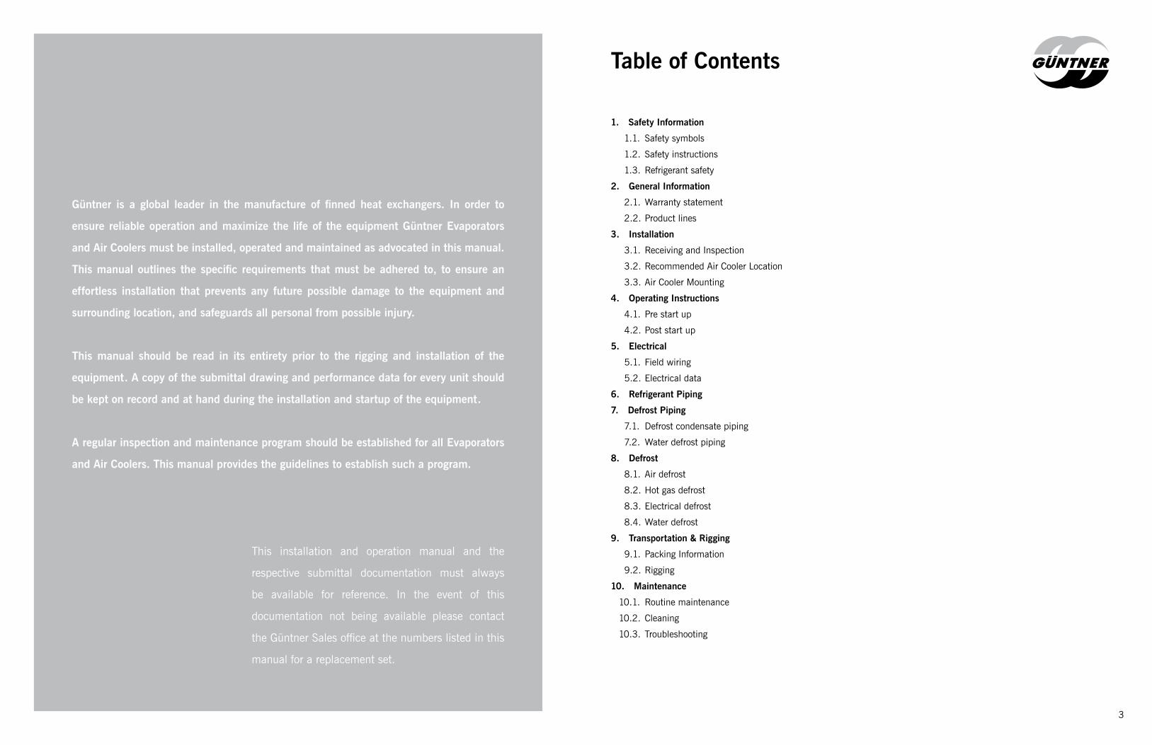
Güntner is a global leader in the manufacture of finned heat exchangers. In order to
ensure reliable operation and maximize the life of the equipment Güntner Evaporators
and Air Coolers must be installed, operated and maintained as advocated in this manual.
This manual outlines the specific requirements that must be adhered to, to ensure an
effortless installation that prevents any future possible damage to the equipment and
surrounding location, and safeguards all personal from possible injury.
This manual should be read in its entirety prior to the rigging and installation of the
equipment. A copy of the submittal drawing and performance data for every unit should
be kept on record and at hand during the installation and startup of the equipment.
A regular inspection and maintenance program should be established for all Evaporators
and Air Coolers. This manual provides the guidelines to establish such a program.
This installation and operation manual and the
respective submittal documentation must always
be available for reference. In the event of this
documentation not being available please contact
the Güntner Sales office at the numbers listed in this
manual for a replacement set.
Table of Contents
1. Safety Information1.1. Safety symbols
1.2. Safety instructions
1.3. Refrigerant safety
2. General Information2.1. Warranty statement
2.2. Product lines
3. Installation3.1. Receiving and Inspection
3.2. Recommended Air Cooler Location
3.3. Air Cooler Mounting
4. Operating Instructions4.1. Pre start up
4.2. Post start up
5. Electrical5.1. Field wiring
5.2. Electrical data
6. Refrigerant Piping7. Defrost Piping
7.1. Defrost condensate piping
7.2. Water defrost piping
8. Defrost8.1. Air defrost
8.2. Hot gas defrost
8.3. Electrical defrost
8.4. Water defrost
9. Transportation & Rigging9.1. Packing Information
9.2. Rigging
10. Maintenance10.1. Routine maintenance
10.2. Cleaning
10.3. Troubleshooting

5
Introduction
Evaporators andAir Coolers
Safety Information
General Information
1. Safety Information
1.1 Safety Symbols
Addresses a hazardous situation which, if encountered,
will result in death or serious injury.
Addresses a hazardous situation which, if encountered,
might result in death or serious injury.
Addresses a hazardous situation which, if encountered,
could result in minor or moderate injury.
Indicates instructions that pertain to safe equipment
operation. Failure to comply with these instructions could
result in damage to the equipment.
1.2 Safety Instructions
• Installation and maintenance must only be carried out by qualified personnel who are
familiar with this type of equipment
• Always wear safety glasses, gloves and head protection when working on the equipment
• Avoid contact with sharp edges and exposed finned surfaces as these can cause painful
lacerations
• All units must be properly evacuated prior to charging the system
• Ensure all power sources are disconnected prior to any service work being done on the
units
• Never apply heat to a sealed refrigeration system
• Keep hands away from fans when the unit is running
• Ensure all mounting bolts are tight and are the correct length for the specific application
• Maintain all safety labels on the unit in good condition. If required replace with new.
1.3 Refrigerant Safety
DANGER!
WARNING!
CAUTION!
NOTICE
WARNING !
Although halocarbon refrigerants are classified as safe refrigerants, certain precautions must be observed when handling them. Refrigerant can be harmful if inhaled. When released to the atmosphere in the liquid state refrigerants evaporate rapidly, freezing anything they contact. Refrigerants must be used and recovered responsibly.Failure to follow this warning may result in personal injury or death.

6 7
2. General InformationGüntner evaporators and air coolers are designed to provide optimum efficiency and
an extended life when properly installed, operated and maintained. It is therefore highly
recommended that a comprehensive maintenance schedule be developed and undertaken on
a regular pre-determined basis. This manual will assist the owner – operator in developing
such a schedule.
This equipment is relatively complicated and the installation, operation, maintenance and
servicing should only be carried out by suitable individuals who are qualified to carry out
these functions. These individuals shall also be familiar with and comply with all applicable
governmental standards and regulations pertaining to the function/s.
The type of refrigerant and method of feed to the evaporator must comply with what is
indicated on the submittal drawings and / or unit’s nameplate.
Design operating pressures, as indicated on the nameplate, must never be exceeded!
Evaporators and all piping systems must be correctly evacuated prior to charging the system
with refrigerant, to ensure the complete removal of moisture and non – condensables from
the entire refrigerant circuit.
2.1 Warranty Statement
Guntner US LLC (“Güntner”) warrants the product to be free from defects in workmanship
and materials under normal usage for a period of 24 months from the date of purchase
(the “Warranty Period”), provided that the product is correctly installed and operated within
the recommended limits of Güntner’s technical documentation. This warranty is only valid
if the product is given normal and proper use and complies with Güntner‘s installation
and maintenance instructions. Güntner assumes no responsibility for repairs to a product
sustaining damages resulting from user modifications, attachments to the product, misuse,
alteration or negligent use.
Güntner, at its option shall repair or replace, free of charge to the buyer, all components of the
product which are or become defective during the Warranty Period as a result of defects in
design, workmanship or materials, ordinary wear and tear excluded, provided, however, that:
• The product is applied correctly
• All operating and installation instructions for the product are complied with
• System component and piping design is in accordance with state-of–the-art HVAC
practice
• Nitrogen or an inert gas is introduced into the piping during the brazing of the piping
installation
In all instances, industry standard refrigeration practices must be observed and utilized
by certified refrigeration technicians, mechanics, pipe fitters, design engineers, etc.
when installing and servicing Güntner products. This warranty shall not include ordinary
maintenance or cleaning of the product, defects in the installation of the product or defects in
turning and moving parts. This warranty also does not cover physical damage to the product,
during transit or otherwise, after purchase of the product but before installation.
The buyer must request repair or replacement of the defective component through a written
notice delivered to Güntner no later than two business days after the buyer becomes aware
of the defect, and the buyer must provide Güntner with the time and opportunity to make
such repair or replacement. Otherwise, Güntner will be released from liability for the defect.
Under no circumstances will Güntner make any repair or replacement without Güntner’s prior
written consent, except to the limited extent permitted by Güntner’s Service Policy.
Any transport and exchange costs for the repair or replacement shall be borne by the buyer.
Güntner shall also not be liable for costs incurred in dismantling or fitting replacement parts or
for any independent inspection undertaken by the buyer. The buyer shall return any allegedly
defective goods, postage or freight paid, to Güntner at the address below. Upon receipt of the
DANGER!
WARNING!
Anhydrous Ammonia (NH3) Specific precaution must be adhered to when people are working with or are exposed to Anhydrous Ammonia.Ammonia is considered a high health hazard because it is corrosive to the skin, eyes, and lungs. Exposure to 300 parts per million (ppm) is immediately dangerous to life and health. Ammonia is also flammable at concentrations of approximately 15% to 28% by volume in air. When mixed with lubricating oils, its flammable concentration range is increased. It can explode if released in an enclosed space with a source of ignition present, or if a vessel containing anhydrous ammonia is exposed to fire. Personal protective equipment must be worn at all times when working with Ammonia. For systems that have an operating charge greater than 10,00lbs a process safety management program is mandatory. More information on this topic is available from OSHA.Failure to follow this warning may result in personal injury or death.
Failure to comply with any of these requirements could result in serious damage to the equipment and / or the property where it is installed, as well as personal injury and / or death to themselves and / or people at the specific location.

Aircoolers / EvaporatorsUnit TypeRefrigerant / Fluid
FamilyHFC NH3 CO2 GlycolGHN AGHN CP/XGHN GGHN GHN Unit cooler / Ceiling hungMDN MDAN MDGN MDN Dual coil
MHNP MANP MCNP MGNP MANP Product coolerMHF MGF MHF Unit cooler / Ceiling hung
GHK GHK GHK Unit cooler / Ceiling hung (steel)GBF AGBF GGBF GBF Workroom coolerMBK AGBK MGBK GBK Process room cooler
goods and inspection thereof, Güntner shall repair or replace, at Güntner’s discretion, the
defective components and shall return the same to the buyer, return postage and freight paid.
This shall constitute full compliance with Güntner’s warranty obligations hereunder. Güntner
accepts no liability for the direct or indirect consequences of any modifications of or repairs
to the product made by the buyer or by a third party without the prior consent of Güntner.
Güntner reserves the right to inspect the product for customer abuse during the warranty
period if abnormal claims against the equipment should arise.
This warranty shall not apply to Güntner products which have been improperly installed or
repaired, or altered in any way outside of the manufacturer’s factory or have been subject
to misuse, negligence, or accident. Equipment or component parts such as valves, electric
motors, electric heaters, and electric accessories manufactured by others and used as part of
or in connection with Güntner products, carry only the warranty of the manufacturer thereof.
This warranty shall be void if equipment has been subjected to negligence, abuse, misuse,
low voltage, corrosive chemicals, excessive pressure, accident, outward damage, or hidden
damage while in transit, or if operated contrary to the manufacturer’s recommendations.
THIS WARRANTY APPLIES ONLY TO THE REPAIR OR REPLACEMENT OF THE PRODUCT
AND/OR ITS COMPONENTS AND EXPRESSLY EXCLUDES RESPONSIBILITY FOR DAMAGES
NOT OCCURRING TO THE PRODUCT AND/OR ITS COMPONENTS THEMSELVES AND FOR
CONSEQUENTIAL DAMAGES. THIS WARRANTY IS THE BUYER‘S EXCLUSIVE REMEDY,
AND ANY IMPLIED WARRANTY OF MERCHANTABILITY OR FITNESS IS EXCLUDED.
GÜNTNER SHALL NOT BE LIABLE TO THE BUYER OR TO ANY CUSTOMER OF THE BUYER
UNDER ANY CIRCUMSTANCES FOR ANY DIRECT OR INDIRECT DAMAGES, INJURY TO
PERSONS OR PROPERTY OR ANY CONSEQUENTIAL OR INCIDENTAL DAMAGES OR LOSS
OF PROFITS, INCLUDING, WITHOUT LIMITATION, LOSS OF REFRIGERANT, LOSS OF
STORED GOODS, LOST SALES, ORDERS, PROFITS OR INCOME, EITHER GROSS OR NET,
ARISING, DIRECTLY OR INDIRECTLY, FROM DEFECTIVE GOODS OR WORKMANSHIP OR
FROM ANY OTHER CAUSE WHATSOEVER.
Table 1
Evaporators & Air Coolers
Installation
Operating Instructions
Electrical
Refrigerant Piping
Defrost Piping
Defrost
Transportation & Rigging
Maintenance
Troubleshooting2.2 Product Lines
The product lines covered in this manual are as per Table 1. Please take note of the respective product families that the
variations are incorporated into.

10 11
3. Installation
3.1 Receiving & Inspection
All units are factory tested to ensure safe operation and quality assembly. Units are
packaged for easy handling and storage, if required, at the job site. Upon delivery inspect
all components for possible shipping damage and / or shortages. Torn or broken packaging,
scratched or damaged panels should be recorded on the delivery receipt and reported to the
carrier immediately. Any damage or shortages discovered after unpacking should also be
reported to the carrier within the allotted time after delivery. The refrigerant circuit/s should
also be inspected to confirm that no leaks have occurred during the shipment. If there is no
holding charge within the unit it is possible that the coil might have been damaged during
shipment. The coil should therefore be pressure tested with dry nitrogen to confirm that it has
no leaks.
Take photos of all damaged equipment if possible. Damaged equipment is the responsibility
of the designated carrier and should not be returned to the manufacturer unless prior approval
is given to do so. Confirm that all items listed on bill of lading are received; especially loose
items such as air throw streamers, inlet hoods and fan guards.
Record any unit damage and shortages on the Bill of Lading and report to the carrier and Güntner factory immediately. Shipping and handling damages are not warranty items.
Compare the data on the nameplate of the unit with the ordering and shipping information
to verify the correct unit is received. Model nomenclature and electrical data should also be
verified with original order.
The unit can be transported with a forklift with the forks extended completely underneath the
skid and generally in the center of the unit. Do not allow the forks to make contact with the
unit. Refer to rigging instructions for greater detail.
The unit is intended for indoor use only. To protect the unit from damage due to the elements,
the unit should be stored in a clean, dry location and away from areas with excessive traffic.
The unit must remain on its skid as this should only be removed at the time of installation.
The unit should be well ventilated at all times during storage.
3.2 Recommended Air Cooler Location
• Units should never be located directly above doorways and should be located as far away
as possible from areas of high infiltration.
• The location of the unit/s must allow for the air pattern to cover the entire room.
• The air inlet side of the coil should be at least 0.8 x face height away from the wall to
prevent obstructed airflow patterns.
• The positioning of the unit in relation to racks, aisles, lighting and / or product should be
such that the leaving air from the unit is not obstructed. The performance of the unit is
realized by the specified air quantity flowing across the coil, and the inlet temperature
of this air as per the submittal documentation. If either of these are compromised the
performance of the unit will be adversely affected.
• The unit should not be connected to ducting on either the air inlet or air leaving side
unless it has been specifically engineered and all external pressures have been accounted
for.
• Position the unit/s, in relation to the compressor room, to realize minimum pipe runs.
• Position the unit/s to minimize condensate line runs.
• The size and shape of the room will determine the number of units (and type thereof)
that should be used and the specific location thereof.
• Sufficient access at the sides, back, underneath and in front of the unit should be available
for maintenance work to be undertaken. 3 foot (1m) minimum is generally sufficient at
the sides and in front of the unit. The 0.8 x face height must be the minimum distance at
the back of the unit – air inlet side. Bottom clearance for the removal of the pan should
be the width of the unit, minimum.
• Units with electric defrost will require an access area the length of the unit on the side
of the unit where the electrical elements is required to be removed from, which is the
refrigerant connection end of the unit.
• Ensuring optimum performance of the unit with unobstructed air flow is the responsibility
of the installing contractor.
3.3 Air Cooler Mounting
Most units can be mounted with threaded rod or bolts suspended from the steel / ceiling
structure above the unit. Care must be taken to ensure that the unit is mounted level so that
condensate drains properly. The steel / ceiling structure from which the unit is supported
must be strong enough to support the unit. All the mounting holes in the hangers on the
unit must be used for supporting the unit. In some instances – e.g. seismic – the installing
contractor might require additional bracing. Foot mount units should be mounted on the floor
or steel structure and either bolted or welded to the support structure. Take care to ensure
that the support structure is level.
Note: Always ensure that
there is no obstruction to the
air intake or discharge for
every unit
NOTICE
12 13
Air Coolers should never be positioned directly above doors and / or door openings. Ensure that a space equal to 0.8 x unit height between the wall and air inlet side is maintained. Always allow for a space equal to the unit height below the unit.Do not stack product directly in front of the unit.
4. Operating Instructions
4.1 Pre Start-up
• Check all electrical and refrigerant connections
• Ensure unit voltage as indicated on nameplate matches supply voltage
• Confirm that the air cooler is wired in accordance with all local and national standards
that are applicable
• Ensure unit is securely mounted and fastened at the hanger points and unit is level
• Confirm all fasteners for fans and motors are tight
• Ensure that all service valves for liquid supply, suction and hot gas feed lines are open
• Confirm proper drainage of condensate from drain pan
• Check operation of condensate drain heaters
4.2 Post Start-up
• Confirm the correct rotation of all impellers
• High moisture load in new rooms can lead to rapid frost accumulation on the finned
surface. It may be necessary to initiate a manual defrost(s).
• Confirm that the air unit has the correct refrigerant charge
• Pull down after start up may result in higher than normal suction pressure, which could
cause nuisance tripping of compressor overloads
• Check drain pan for proper drainage
• Thermostatic expansion valves must be checked for proper superheat settings
• ALL adjustable controls and valves must be field adjusted to meet desired operating
conditions
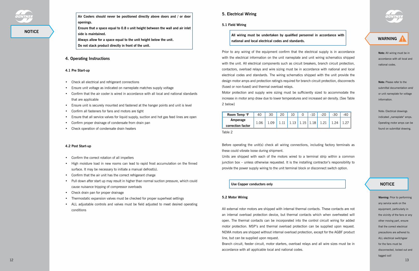
5. Electrical Wiring
5.1 Field Wiring
Prior to any wiring of the equipment confirm that the electrical supply is in accordance
with the electrical information on the unit nameplate and unit wiring schematics shipped
with the unit. All electrical components such as circuit breakers, branch circuit protection,
contactors, overload relays and wire sizing must be in accordance with national and local
electrical codes and standards. The wiring schematics shipped with the unit provide the
design motor amps and protection rating/s required for branch circuit protection, disconnects
(fused or non-fused) and thermal overload relays.
Motor protection and supply wire sizing must be sufficiently sized to accommodate the
increase in motor amp draw due to lower temperatures and increased air density. [See Table
2 below]
Before operating the unit(s) check all wiring connections, including factory terminals as
these could vibrate loose during shipment.
Units are shipped with each of the motors wired to a terminal strip within a common
junction box – unless otherwise requested. It is the installing contractor’s responsibility to
provide the power supply wiring to the unit terminal block or disconnect switch option.
5.2 Motor Wiring
All external rotor motors are shipped with internal thermal contacts. These contacts are not
an internal overload protection device, but thermal contacts which when overheated will
open. The thermal contacts can be incorporated into the control circuit wiring for added
motor protection. MSP’s and thermal overload protection can be supplied upon request.
NEMA motors are shipped without internal overload protection, except for the AGBF product
line, but can be supplied upon request.
Branch circuit, feeder circuit, motor starters, overload relays and all wire sizes must be in
accordance with all applicable local and national codes.
Room Temp °F 40 30 20 10 0 -10 -20 -30 -40Amperage
correction factor1.06 1.09 1.11 1.13 1.15 1.18 1.21 1.24 1.27
Use Copper conductors only
Note: All wiring must be in
accordance with all local and
national codes.
Note: Please refer to the
submittal documentation and/
or unit nameplate for voltage
information.
Note: Electrical drawings
indicated „nameplate“ amps.
Operating motor amps can be
found on submittal drawing.
Warning: Prior to performing
any service work on the
equipment, particularly in
the vicinity of the fans or any
other moving part, ensure
that the correct electrical
precautions are adhered to.
ALL electrical switchgear
for the fans must be
disconnected, locked out and
tagged out!
All wiring must be undertaken by qualified personnel in accordance with national and local electrical codes and standards.
Table 2
NOTICEWARNING !
NOTICE

14 15
6. Refrigerant Piping
All refrigerant piping and piping components should be installed in accordance with the
either the IIAR Refrigeration Piping Handbook [Ammonia or Carbon Dioxide] or the relevant
“Systems and Practices” chapters of the ASHRAE Handbook [Halocarbons or Brines].
Units are supplied with multiple refrigerant connections, factory sealed and pressurized to
30 psig (+/- 2 bar) and should remain sealed until ready to be piped into the refrigeration
system. The connections on the units are not designed to support any field piping or piping
components whatsoever. Field piping should be designed and supported independent of
the unit, to minimize the transmission of vibration and allow for thermal expansion and
contraction, and to inflict no load on the unit connections.
Units with stainless steel tubes and piping are supplied with black steel stubs at the end
of each connection piece to facilitate field piping / welding. (These can be supplied as
stainless steel if required.) The supplied connections should not be used as a reference
for system piping. System piping dimensions should be based on industry accepted good
engineering design principles.
7. Defrost Piping
7.1 Condensate Drain Piping
Condensate drain lines should be kept as short as possible within the refrigerated space
and should be individually trapped. All condensate drain lines should be pitched at a
3/8” inclination per linear foot (3 cm/m). Drain lines from each unit should be piped to
an independent trap to prevent the migration of warm air through the condensate drain
lines. This is critical when multiple units drain lines are piped to a common drain line
header. The reverse flow (migration) will cause ice buildup in the drain pans if the room
temperature is below 32°F (0°C). This ice buildup will block the drain outlet and trap the
condensate within the drain pan. Traps should preferably be positioned outside of freezer
spaces and in warm locations. When the trap is located in an area where the temperature
never drops below freezing the trap should not be heated. If heated there is a possibility of
the condensate within the trap boiling off and drying out the trap.
All condensate drain piping and traps, if unavoidable, within space temperatures below
34°F (1°C) must be heated and insulated to prevent freezing. Heating elements must be
energized continuously.
The values below are generally accepted within the industry for drain line heater wattages:
+20°F (-7°C) >>> 10W / linear foot (33 W/m)
0°F (-18°C) >>> 20W / linear foot (65 W/m)
-20°F (-29°C) >>> 30W / linear foot (100 W/m)
Condensate drain line sizing should be the same dimension, at a minimum, as the outlet
connection on the unit. A union piped into the outlet from the unit is recommended and will
enable disconnecting the drain line for heater repair / replacement and / or maintenance.
NOTE: Always use two wrenches to fasten the condensate drain pipe union. DO NOT apply
torque to the fitting on the drain pan.
Always use two wrenches to fasten the condensate drain pipe union. DO NOT apply torque to the fitting on the drain pan.
7.2 Water Defrost Piping
All water lines within refrigerated spaces must be insulated and heat traced to prevent
these lines freezing. Lines must also be pitched up to ½” per linear foot to allow the water
to drain at the completion of the defrost period.
A solenoid valve should be installed in the water supply line to each unit, which will open
under the control of an automated timer to allow water flow to the units. [See water defrost
section for more details on pipe sizing and control requirements]
Drain line and water defrost piping
NOTICE

1716
8. Defrost
All air coolers operating with coil surface temperatures beneath freezing [32°F (0°C)] will
experience some form of frost accumulation. In order to maintain the performance of the
coil it is imperative that some form of defrost is incorporated into the system. Typically the
defrosting of the coil will be accomplished by; air (for rooms above 36°F (2.2°C)), hot gas,
electric or water. (See Table 3 below)
Recommended Defrost Types based on Room Temperature
TemperatureAir
DefrostWaterDefrost
ElectricDefrost
Hot Gas
DefrostHIGH Temperature > 40°F (4.4°C) yes no no noMEDIUM Temperature > 20°F (-6.7°C) < 40°F(4.4°C) no yes yes yesLOW Temperature < 20°F (-6.7°C) no yes yes yesULTRA LOW Temperature < -40°F (-40°C) no no yes yes
*** Insulated pans are recommended for any application with a room temperature below freezing.
8.1 Air Defrost
For applications where the room temperature is above freezing, defrosting of the finned
surface area is possible by closing the liquid feed to the coil and allowing the fans to
continue running. The warmer air passing over the coil will melt the frost accumulation,
but dependent on the frost formation and room temperature will determine the rate of frost
melt. It is therefore recommended to only use air defrost when the room temperature is
above 36°F (2.2°C).
8.2 Hot Gas Defrost
Most refrigeration systems incorporate a central compressor room. This is an ideal source
for hot gas and only requires the piping to make it available for the evaporators. The latent
heat content of the vapor makes this method of defrost very effective and is essentially
a byproduct of the refrigeration system. It is essential that not more than 1/3 of the
evaporators in the system are defrosted simultaneously.
Reverse cycle defrost is not recommended for non – commercial applications. Therefore
forward cycle should always be used which requires a three pipe arrangement at the
evaporator, the third pipe being the hot gas supply line. The hot gas flow through the unit
should always be a series arrangement, first through the pan section and then into the coil
from top to bottom. For DX applications where a distributor is used the hot gas feed into the
coil should always be through the distributor, not reverse cycle.
Evaporators with capacities greater than 15 tons (52 kW) should incorporate a soft start hot
gas solenoid valve in the valve station. This valve will allow the coil to ease up to the hot
Table 3
gas pressure and prevent problems such as check valve chatter, liquid hammer and piping
vibrations.
The pump out phase is critical to optimum defrost performance. Additionally if liquid is still
present in the tubes when the hot gas enters the coil, condensate induced hydraulic shock
is possible which can have severe consequences, including the rupturing of the pipes!
Hot gas piping located within the refrigerated spaces and / or outdoors in cold climates
must be insulated. It is also recommended to have liquid drainers installed in these lines to
prevent liquid condensate entering the evaporator during the defrost phase.
The hot gas mass flow supplied to the evaporator is dependent on the capacity of the unit
and the hot gas pressure entering the evaporator. More often than not there is insufficient
volume flow to the evaporator than a hot gas pressure or temperature issue, that results in
poor defrost performance.
Recommended hot gas pressures at the evaporator should be in accordance with Table 4:
Refrigerant Required pressure at evaporatorR22 90 - 110 psig [~6 - 7.5 bar]
R404a 115 - 140 psig [~8 - 9.5 bar]R507A 115 - 140 psig [~8 - 9.5 bar]R134a 50 - 65 psig [~3.5 - 4.5 bar]R410a 155 - 185 psig [~10.5 - 12.5 bar]NH3 80 - 100 psig [~5.5 - 7 bar]
The sequence of hot gas defrost operation and recommended stage duration is indicated in Table 5:
Hot Gas Defrost - Sequence of Operation
Defrost StagesTime, in minutes (approx.)
Control Valves
Liquid solenoid(LSV)
Suction solenoid(SSV) De
lay
Soft hot gas solenoid
valve (SHGSV)
Hot gas solenoid
valve (HGSV)
Bleed solenoid
valve (BSV)
Fan motor/motprs running
Refrigeration mode xx yesPump out period 10 - 30 yesDelay 5-10 secs noSoft gas period 1 - 2 noHot gas period 5 - 30 noEqualizing period 2 - 5 noFan delay period 1 - 3 noRefrigeration mode xx yes
= Solenoid open
Table 4
Table 5

18 19
Recommended Wattages for Electric DefrostWattage per ft2 of coil
surface areaMEDIUM Temperature > 20°F (-6.7°C) < 40°F(4.4°C) 6 to 8LOW Temperature < 20°F (-6.7°C) 8 to 12ULTRA LOW Temperature < -40°F (-40°C) 12 to 15
8.3 Electric Defrost
For DX halocarbon applications the most common method of defrost is with electric heater
rods. The heaters are placed in both the coil and the pan section. The heater rods are
installed within support tubes in the coil bundle and held in place with “C” clips, which are
positioned such that there is sufficient space for the rods to expand and contract due to the
thermal changes. All heater rods require a pull space for removal and / or replacement that
is equal to 0.8 x the coil length.
The heater rods for the drain pan section are attached to the underside of the heater sheet
which is positioned below the coil and held in place with clips. All wiring for heater rods are
terminated within a junction box located on the end tube sheet of the unit.
Wattages for heater elements will be dependent on the room temperature, and this should
be carefully checked at the time of selection (see Table 6 below).
8.4 Water Defrost
For water defrost to function correctly it is essential that an adequate supply of suitably
warm water [> 55°F (13°C)] is available at the job site. The defrost method consists of the
water being evenly distributed over the coil from a water distribution pan positioned on top
of the coil. Water flow is required until all frost has been melted off the finned surface.
The flow rate should be controlled by regulating a balancing valve located at the inlet to each
unit. Refer to Table 7 below for water flow pipe sizing. The flow must be adjusted to ensure
full coverage of the coil plan area and take care not to allow the water distribution pan to
overflow. Flow rate requirements for each unit are indicated on the submittal drawings.
During the set up and commissioning the defrost operation must be carefully observed to
ensure that the entire coil is cleared of frost. The time required to clear the coil can vary
from three to fifteen minutes – and should never exceed fifteen minutes. If this is the case
typically inadequate water supply and / or inlet temperature is too low.
All water lines within refrigerated spaces must be insulated and heat traced to prevent these
lines freezing. Lines must also be pitched up to ½” per linear foot to allow the water to
drain at the completion of the defrost period.
Large volumes of water also require adequately sized condensate drain lines (see Table 8
below). Condensate drain lines must have a minimum inclination of ½” per linear foot and
sufficient fall from the drain pan outlet is required prior to entering the trap in order for the
Table 6
static head to overcome the pressure drop of the water flow through the trap. Traps should
always be situated outside the refrigerated space. Condensate lines must be heat traced and
insulated.
Recommended Condensate Drain Line Diameters for Water DefrostFlow rate from drain pan in gpm
15 25 40 60 85 165 250
Pipe Diameter in Inches
2 2 1/2 3 3 1/2 4 5 6
Water Flow Rates for Different Pipe Diameters in gpmPressure drop in
psi / 100
Pipe Diameter in Inches
1 1 1/4 1 1/2 2 2 1/2 3 4 5
2 8 17 23 50 89 144 307 5535 13 26 38 81 146 236 504 90610 19 28 56 118 213 344 733 131815 24 49 69 147 265 428 912 164020 28 56 81 172 309 500 1065 191630 35 70 101 214 385 622 1326 238540 40 81 117 250 450 727 1549 2786
9. Transportation & Rigging9.1 Packing Information
All Güntner air coolers are crated such that they can be removed from a truck with a forklift
or a crane. When lifting any unit with a forklift it is essential that the forks extend the full
span of the skid and must not make contact with any portion of the unit.
Units are either plastic wrapped with a heavy duty plastic wrap and positioned on a skid or
have wood crating around and on top of the unit, also placed on a skid.
When using a crane to lift the unit use only the designated lifting points as detailed on the
rigging drawing attached to the unit at the time of shipping. Always ensure that the lifting
points are balanced and evenly spread.
Leave the skid on the unit and use this to lift the unit with forklift. Only remove the skid
once the unit is mounted to the ceiling supports. Ensure all support rods are adequately
sized to support the load. [Refer to the submittal drawings for the unit weight]
Never lift unit by placing forks in direct contact with the lower portion of the unit or the drain pan
Table 7
Table 8
Warning: Prior to performing
any service work on the
equipment, particularly in the
vicinity of the fans or any other
moving part, ensure that the
correct electrical precautions
are adhered to. ALL electrical
switchgear for the fans must
be disconnecte, locked out and
tagged out!
NOTICE
2120
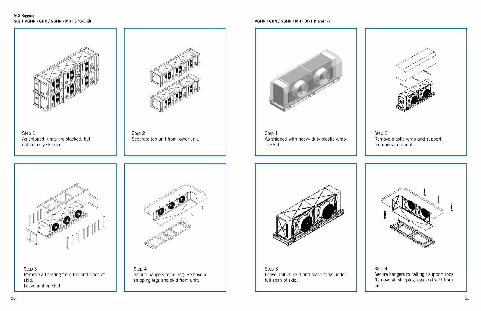
9.2.1 AGHN / GHN / GGHN / MHF (<071 Ø)
Step 1As shipped, units are stacked, but individually skidded.
Step 2Separate top unit from lower unit.
Step 3Remove all crating from top and sides of skid.Leave unit on skid.
Step 4Secure hangers to ceiling. Remove all shipping legs and skid from unit.
AGHN / GHN / GGHN / MHF (071 Ø and >)
Step 1As shipped with heavy duty plastic wrap on skid.
Step 2Remove plastic wrap and support members from unit.
Step 3Leave unit on skid and place forks under full span of skid.
Step 4Secure hangers to ceiling / support rods. Remove all shipping legs and skid from unit.
9.2 Rigging
2322
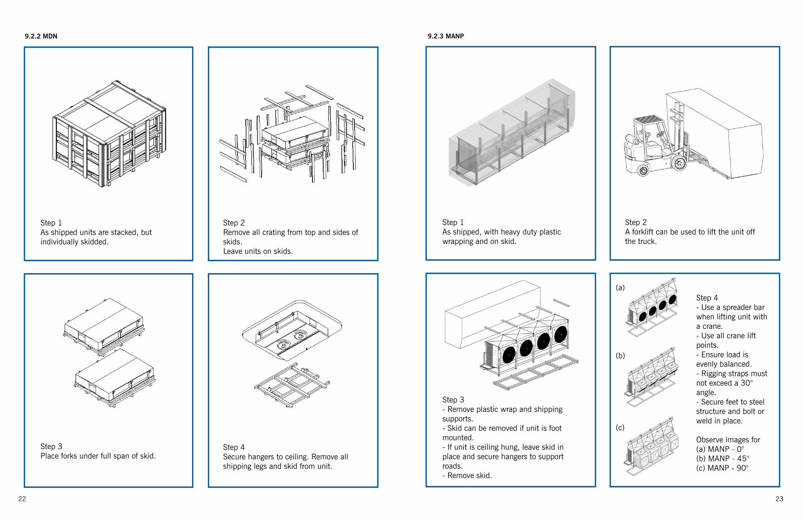
9.2.2 MDN
Step 1As shipped units are stacked, but individually skidded.
Step 2Remove all crating from top and sides of skids.Leave units on skids.
Step 3Place forks under full span of skid.
Step 4Secure hangers to ceiling. Remove all shipping legs and skid from unit.
9.2.3 MANP
Step 1As shipped, with heavy duty plastic wrapping and on skid.
Step 2A forklift can be used to lift the unit off the truck.
Step 3- Remove plastic wrap and shipping supports.- Skid can be removed if unit is foot mounted.- If unit is ceiling hung, leave skid in place and secure hangers to support roads.- Remove skid.
Step 4- Use a spreader bar when lifting unit with a crane.- Use all crane lift points.- Ensure load is evenly balanced.- Rigging straps must not exceed a 30° angle.- Secure feet to steel structure and bolt or weld in place.
Observe images for (a) MANP - 0°(b) MANP - 45°(c) MANP - 90°
(b)
(c)
(a)

2524
9.2.4 GBF / AGBF / GGBF
Step 1As shipped with heavy duty plastic wrap on skid.
Step 2Remove plastic wrap and support members from unit.
Step 3Leave unit positioned on skid. Place forks under full span of skid.
Step 4Secure hangers to ceiling. Remove all shipping legs and skid from unit.
9.2.5 MBK / AGBK / MGBK
Step 1As shipped units are stacked, but individually skidded.
Step 2Remove all crating from top and sides of skids.Leave units on skids.
Step 3Place forks under full span of skid.
Step 4Secure hangers to ceiling. Remove all shipping legs and skid from unit.
26 27
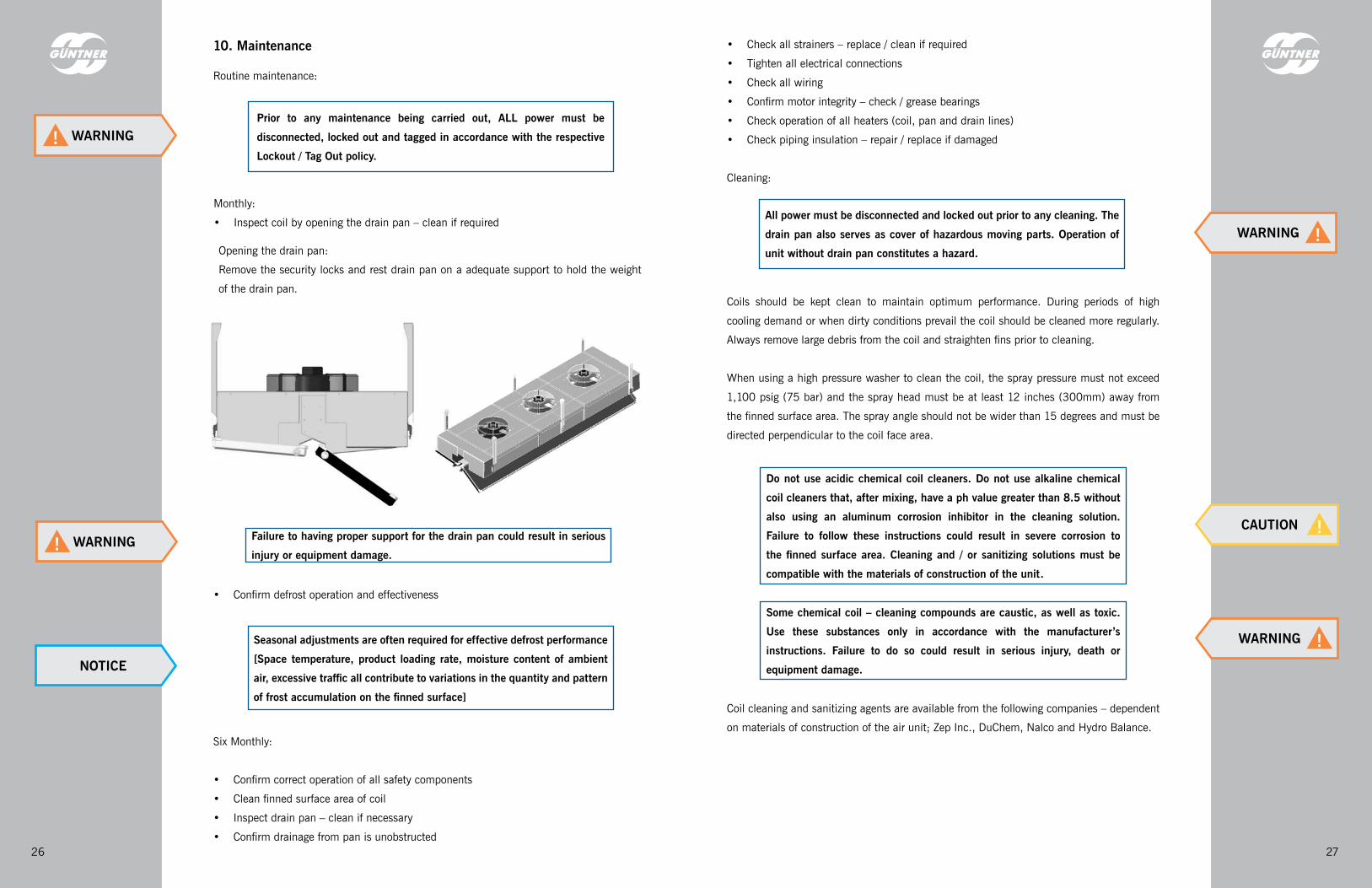
10. Maintenance
Routine maintenance:
Prior to any maintenance being carried out, ALL power must be disconnected, locked out and tagged in accordance with the respective Lockout / Tag Out policy.
• Confirm defrost operation and effectiveness
Seasonal adjustments are often required for effective defrost performance [Space temperature, product loading rate, moisture content of ambient air, excessive traffic all contribute to variations in the quantity and pattern of frost accumulation on the finned surface]
Six Monthly:
• Confirm correct operation of all safety components
• Clean finned surface area of coil
• Inspect drain pan – clean if necessary
• Confirm drainage from pan is unobstructed
All power must be disconnected and locked out prior to any cleaning. The drain pan also serves as cover of hazardous moving parts. Operation of unit without drain pan constitutes a hazard.
Do not use acidic chemical coil cleaners. Do not use alkaline chemical coil cleaners that, after mixing, have a ph value greater than 8.5 without also using an aluminum corrosion inhibitor in the cleaning solution. Failure to follow these instructions could result in severe corrosion to the finned surface area. Cleaning and / or sanitizing solutions must be compatible with the materials of construction of the unit.
Some chemical coil – cleaning compounds are caustic, as well as toxic. Use these substances only in accordance with the manufacturer’s instructions. Failure to do so could result in serious injury, death or equipment damage.
Coils should be kept clean to maintain optimum performance. During periods of high
cooling demand or when dirty conditions prevail the coil should be cleaned more regularly.
Always remove large debris from the coil and straighten fins prior to cleaning.
When using a high pressure washer to clean the coil, the spray pressure must not exceed
1,100 psig (75 bar) and the spray head must be at least 12 inches (300mm) away from
the finned surface area. The spray angle should not be wider than 15 degrees and must be
directed perpendicular to the coil face area.
Coil cleaning and sanitizing agents are available from the following companies – dependent
on materials of construction of the air unit; Zep Inc., DuChem, Nalco and Hydro Balance.
WARNING!
NOTICE
WARNING !
CAUTION !Failure to having proper support for the drain pan could result in serious injury or equipment damage.
Opening the drain pan:
Remove the security locks and rest drain pan on a adequate support to hold the weight
of the drain pan.
WARNING!
WARNING !
• Check all strainers – replace / clean if required
• Tighten all electrical connections
• Check all wiring
• Confirm motor integrity – check / grease bearings
• Check operation of all heaters (coil, pan and drain lines)
• Check piping insulation – repair / replace if damaged
Cleaning:
Monthly:
• Inspect coil by opening the drain pan – clean if required

2928
Air Cooler Troubleshooting Guide
Symptoms Possible Cause Corrective Action1. Fan motor(s) not running Main switch open Close switch
Blown fuse(s) "Replace fuse(s) Check for short circuits and / or overload conditions"
Faulty motor(s) Replace motor(s)Unit currently in defrost mode Wait for completion of defrost cycle
2. Elevated Room Temperature Incorrect thermostat setting (too high) Adjust thermostat settingLow refrigerant charge Add refrigerantSuperheat setting too high Adjust thermal / electronic expansion
valveEvaporators are undersized for room / load
If design load has increased operating conditions might require change, or add more evaporators to the space
Coil iced up Manually defrost coil and adjust defrost settings
High infiltration load Ensure all openings in space are properly sealed
Low refrigerant flow into evaporator "Check fans / motors for correct operation (rotation) Check and clean strainers Adjust hand expansion valve setting"
3. Ice accumulation on ceiling around evaporator and / or around fans, motors and fan nozzles
Defrost duration too long Adjust defrost settingsToo many defrosts Decrease defrost frequencyDefective defrost timer / thermostat / defrost relief regulating valve
Repair or replace defective components
Fan delay not set correctly Adjust setting for fan delay duration4. Coil not clearing of frost during defrost cycle
Insufficient defrost cycles in 24 hour period
Increase defrost frequency
Defrost cycle too short Adjust defrost setting for increased duration
Hot gas volume insufficient Increase flow to evaporatorHot gas temperature / pressure too low Increase hot gas temperature / pressureDefective timer or relief regulating valve
Replace timer or regulating valve
Fans continue to run when in defrost mode
Adjust settings to prevent fans running
Excessive infiltration load Ensure all openings in space are properly sealed
11. Troubleshooting 5. Uneven coil frosting Defective heater element(s) Replace element(s)Unit located too close to a door or opening
Relocate evaporator
Refrigerant feed insufficient to properly feed evaporator
"Check and clean strainers Adjust hand expansion valve setting Adjust TXV settings"
Defrost duration too short Adjust defrost settingsTXV too small Replace with correct TXVFans not functioning correctly Check fans and motors for correct
operation, replace if defective6. Ice accumulation in drain pan Defective heater element(s) Replace element(s)
Unit incorrectly pitched Check and adjust accordinglyCondensate drain line plugged Clean drain lineDefective drain line heater Replace heaterInsufficient hot gas flow to unit Increase hot gas flow to unitDefective defrost timer / thermostat / defrost relief regulating valve
Repair or replace defective components
7. Low Airflow Coil iced up See symptoms 3, 4 and 5 aboveUnit mounted too close to a wall Reposition unit for unobstructed airflowVFD output too low Adjust VFD settingsFans not functioning correctly Check fans and motors for correct
operation, replace if defective8. Insufficient Airthrow Air discharge area obstructed Remove / replace any items causing an
obstruction to the discharge airFit streamers on air unit
NOTICE: Ice has a much higher density than frost and will require more time to melt than the normal frost formation on a coil. Ice is typically formed from melted frost which is not drained from the unit during the defrost cycle. Over time this accumulation can become significant and can lead to other problems at the evaporator. It is essential that air coolers are regularly inspected to ensure effective defrost performance. Manual ice removal may be required in some instances to remove this ice accumulation.
Prior to any inspection involving frost or ice accumulation, the coil and all sheet metal components must be thoroughly cleaned of all ice accumulation!
NOTICE
29

30 31
NOTES NOTES
Subj
ect t
o te
chni
cal a
men
dmen
ts w
ithou
t prio
r not
ice.
IO
M 1
01 /
V1.1
/ EN
G / 0
8.20
15
Air Cooled CondensersAir Cooled Fluid CoolersAir CoolersEvaporatorsEvaporative CondensersEvaporative Fluid CoolersClosed Circuit Fluid Coolers
Guntner U.S. LLC110 W. Hillcrest Blvd. Suite 105Schaumburg, IL 60195USA
Phone: + 1 847 781 0900www.guntnerus.com