INSTALLATION OPERATION & MAINTENANCE · PDF fileINSTALLATION OPERATION & MAINTENANCE MANUAL...
17
Virgo Virgo INSTALLATION INSTALLATION OPERATION & OPERATION & MAINTENANCE MAINTENANCE MANUAL MANUAL TRUNNION-MOUNTED BALL VALVE VIRGO ENGINEERS LIMITED VIRGO ENGINEERS LIMITED (An ISO 9001, API & PED Certified Company) J / 517, MIDC Bhosari, Pune – 411 026, INDIA. Phone: +91-20-7474481, 7470402 Fax: +91-20-7470772. E-mail : [email protected] Website: www.virgoengineers.com
Transcript of INSTALLATION OPERATION & MAINTENANCE · PDF fileINSTALLATION OPERATION & MAINTENANCE MANUAL...

Virgo Virgo
INSTALLATIONINSTALLATIONOPERATION &OPERATION &
MAINTENANCEMAINTENANCEMANUALMANUAL
TRUNNION-MOUNTED BALL VALVE
VIRGO ENGINEERS LIMITEDVIRGO ENGINEERS LIMITED(An ISO 9001, API & PED Certified Company)
J / 517, MIDC Bhosari, Pune – 411 026, INDIA.Phone: +91-20-7474481, 7470402Fax: +91-20-7470772.E-mail : [email protected]: www.virgoengineers.com

Content
General Instructions
1. Introduction 1
2. Transportation, Reception and Storage. 1
3. Do’s and Don’ts. 2
4. Installation. 3
5. Operation of the valve. 5
6. Maintenance. 6
7. Trouble Shooting. 8
Disassembly and Assembly Instructions
9Trunnion Mounted Ball Valves(Two Piece Design/Three Piece Design)

Ball Valve Three Piece / Two Piece Design GENERAL INSTRUCTIONS
\\Cad\data\USERS\SPECS\ISO\OPRMANL\IOMBVD01\DOC\2P3PT01.DOC 1
1. Introduction
Scope
The purpose of this manual is to ensure that the valves supplied are properly installed andmaintained to give trouble free performance. For better understanding of product and themaintenance requirements, see enclosed exploded view of the valve, where different partsare identified.
Identification of Valve
Specifications of the valve are marked on the body or on an identification plate or both, priorto shipment.
1.1 Identification of Valve
2. Transportation, Reception and Storage
While unpacking the valves, check that the valves & any accessories have not beendamaged during transportation.
Note: If the valve or any of its accessories is damaged or missing during transportation,inform the same to the Factory / Branch Office.
CAUTION!Placing the valves directly on the ground or on a concrete floor should be avoided!
Valve open or close position is indicated on the handle sleeves for lever operated valves oron the top of the gearbox for gearbox operated valves.
All valves are delivered with the ball port in full open position and ends protected withprotective end caps to avoid the entry of debris, other solid particles during transportation anddamage to serrations.
Note: When the valve operation is by single acting pneumatic actuator, where spring closesthe ball port and air supply open the ball port, the valves are supplied with ball port in closedposition. Special care must be taken to avoid damage to the surface of the ball.
All wrapping and protection on the valves should not be removed until the valve is ready forinstallation. If protective end caps are removed for the examination of the valve internals,they should be refitted immediately.
We recommend storing the valves indoor, in a dry and dust free atmosphere. Avoid anyaccidental damage during storage.
PUNE, (INDIA)VIRGO ENGINEERS LTD

Ball Valve Three Piece / Two Piece Design GENERAL INSTRUCTIONS
\\Cad\data\USERS\SPECS\ISO\OPRMANL\IOMBVD01\DOC\2P3PT01.DOC 2
2.1 Storing the Valve
If the valves are stored for a longer time, then all the valves should be cleaned andhydrostatic/pneumatic shell/seat tested before installation in consultation with the Factory /Branch Office.
CAUTION!When handling the valve or the valve package, bear in mind its weight.Place the rope securely around the valve body or use lifting hooks (provided for valvesgreater than 250 kg.) while handling the valve. Special care should be taken not to damagethe lever or gearbox or actuator.
2.2 Lifting of Valve3. Do’s and Don’ts
Note: User should ensure that he has read and understood the Do’s and Don’ts beforeInstallation, Operation and Maintenance of the valve is carried out. In case of any clarificationcontact the Factory /Branch Office.
Do’s
• Use the valve for the specified application as agreed between the manufacturer & thepurchaser.
• Read Installation, Operation and Maintenance manual before installing, operating orrepairing any valve.
• The purchaser / end users should train their employee for the safe use of the valve.• Ensure that nuts/bolts are tightened to specified torque value.• Periodically ensure the electrical continuity of the valve.• Open or close the valve slowly to avoid hammering effect on the valve and the pipeline.• Always replace the damaged parts with genuine and recommended parts only.

Ball Valve Three Piece / Two Piece Design GENERAL INSTRUCTIONS
\\Cad\data\USERS\SPECS\ISO\OPRMANL\IOMBVD01\DOC\2P3PT01.DOC 3
• Be aware of the type of media & the environment (explosive, highly flammable, toxic,oxidising etc.) in which the valve is to be used. Protect the peoples & the environmentfrom any harmful or poisonous substances.
• Carefully read the Cautions / Warning plates on the valve.• Customer to take care of residual hazard (if applicable or as informed by the
manufacturer) at his premises to avoid any major damage.• The valve body may be very hot or very cold during use. Protect the people against burns
or cold injuries.
Don’ts
• Specification of the valve is marked on the body or on the nameplate or both, prior toshipment. Users to ensure that the maximum operating conditions are not exceeded.
• Do not keep the valve open at any intermediate position.• Do not try to rectify the valve leakage by reworking of seats. Leaking seats have to be
replaced with the new Virgo genuine seats.• The threaded connections of the valve body for the drain and the vent lines are sealed by
threaded plugs. These plugs should not be removed as long as the valve is underpressure.
• Modification in the valve should not be carried out.
4. Installation
Before installing a new valve in the line, make sure that the valve should be checked foridentification purpose and ensure that characteristics of the valve matches to those specifiedfor piping specifications, for the line where that is to be mounted. Nameplate instructions andTag plates will give the necessary information. If this information is missing, consultFactory/Branch office.
When taking out the valve from storage a careful check should be made to ensure that thevalve is not being damaged during the storage period.
Before installation of the valves, remove the end protectors & check that serrations on flangeface are not damaged and the valve bore is clean. Clean the valve, if necessary.
CAUTION!• Ensure pipeline is fully cleaned before installation of the valve into the pipeline.
pipeline debris, scaling, etc will damage the soft seat inserts of the valve andcause seat leakage during commissioning.
• During commissioning and pipeline flushing, valve should be kept fully open toprevent damage to the internal parts.
Note: One way to prevent damage to the valve during flushing and testing of pipelines is tosubstitute them by spool pieces. If use of spool pieces is not possible, it is essential that thevalve is kept in fully open condition and it is also advisable to install temporary strainers atcritical places to protect soft Seats of the valves from solid particles.
Ball valves are designed for bi-directional flow unless the ball is drilled for cavity relief. For theball with cavity relief hole, ensure that the installation of the valve is correct with respect toflow direction arrow marked on valve.
Valves can be mounted in a horizontal (with stem upwards only) or vertical positiondepending on the pipeline routing. However we do not recommend installing the Valve withthe Actuator on the underneath side because dirt in the pipeline may then enter the Bodycavity and damage the gland packing.

Ball Valve Three Piece / Two Piece Design GENERAL INSTRUCTIONS
\\Cad\data\USERS\SPECS\ISO\OPRMANL\IOMBVD01\DOC\2P3PT01.DOC 4
It may be necessary to firmly support the pipeline in order to protect the valve from excessstress & to reduce the pipeline vibrations. To facilitate servicing, it is preferable that the valveshould be supported by the body, using the pipe clamps and supports. Do not fasten supportsto the flange bolting or to the actuator. Refer Figure No. 4.2.
4.1 Avoid this mounting position. 4.2 Supporting the valve
I. Flanged End Valves :
Don’t attempt to correct the misalignment, by means of flange bolts.
During the tightening operation, ensure that piping stresses are not transferred to the valve.
Excessive over-tightening of flange studs can cause damage and/or leakage on the endflanges or body-to-body end joints.
II. Weld End Valves :
Note: A qualified Welder must do welding operation. The welding procedure should beaccording to ASME Boiler And Pressure Vessel Code Section IX.
CAUTION!Don’t allow temperature of the valve body seat area to exceed 200 °F (940C) to preventseat and seal damage during welding operation. It is recommended that thermal chalksare used to check the temperature.
Note : Any damage to the seats due to the temperature above 200°F (94°C) can cause thevalve leakage. It is recommended that the customer keeps spares kit at his end.
CAUTION!Ensure that weld spatter does not fall over ball & body seals. This may damage thesealing surfaces & seals.
After welding, flush the pipeline when the valve is in open condition to remove the weldspatter formed during welding and then operate the valve 3-4 times in order to ensure theproper operation of the valve.
Butt Weld End Valves :
Ensure a gap of 0.08” to 0.12” between the valve ends and pipeline as per ASME weldingstandard and tack weld the pipeline and the valve ends. After ensuring the proper alignmentbetween the pipeline and the valve, weld the valve end.
Ball Valve Three Piece / Two Piece Design GENERAL INSTRUCTIONS
\\Cad\data\USERS\SPECS\ISO\OPRMANL\IOMBVD01\DOC\2P3PT01.DOC 5
5. Operation of the Valve :
For lever operated valves, the hand lever is either assembled with the valve or shipped loosedepending upon the size of the valve / handlever.
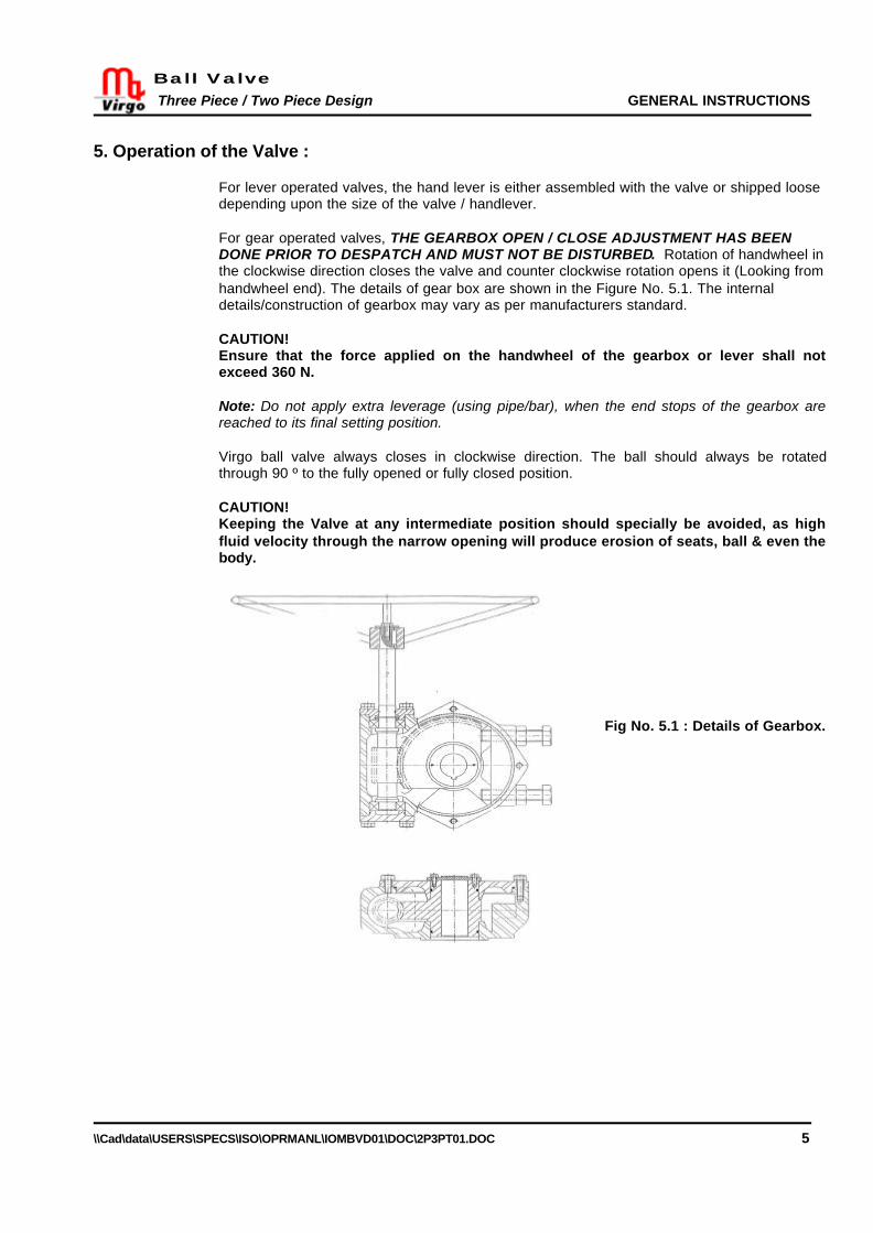
For gear operated valves, THE GEARBOX OPEN / CLOSE ADJUSTMENT HAS BEENDONE PRIOR TO DESPATCH AND MUST NOT BE DISTURBED. Rotation of handwheel inthe clockwise direction closes the valve and counter clockwise rotation opens it (Looking fromhandwheel end). The details of gear box are shown in the Figure No. 5.1. The internaldetails/construction of gearbox may vary as per manufacturers standard.
CAUTION!Ensure that the force applied on the handwheel of the gearbox or lever shall notexceed 360 N.
Note: Do not apply extra leverage (using pipe/bar), when the end stops of the gearbox arereached to its final setting position.
Virgo ball valve always closes in clockwise direction. The ball should always be rotatedthrough 90 º to the fully opened or fully closed position.
CAUTION!Keeping the Valve at any intermediate position should specially be avoided, as highfluid velocity through the narrow opening will produce erosion of seats, ball & even thebody.
Fig No. 5.1 : Details of Gearbox.

Ball Valve Three Piece / Two Piece Design GENERAL INSTRUCTIONS
\\Cad\data\USERS\SPECS\ISO\OPRMANL\IOMBVD01\DOC\2P3PT01.DOC 6
6. Maintenance :
CAUTION!Observe the Cautions/Safety precautions before carrying out the maintenance.
Routine checks by the user
• The following points will give guidelines for routine maintenance.• Check the tightness of nuts/bolts between the body/body adapter, the bracket/stem
housing, and the body/trunnion.• Ensure that the performance of the valve is satisfactory.• Ensure the electrical continuity of the valve.• Ensure that no leakage is being observed from the valve.• Frequent observation is recommended under extreme application / condition.• Periodically flush the sealant ports with suitable valve cleaner to flush debris from the
sealant system.• Mounting studs/nuts of the worm gearbox may be checked for tightness and retightened
if necessary.
Preventive Maintenance
In order to avoid valve failure during operation, all valves in a process plant should beperiodically inspected thoroughly to detect the wear of ball, seats, seals and even the body. Itis recommended that on such occasion’s seats, gaskets, seals and packing should bereplaced. Check the electrical continuity of the valve and the pipeline.
The type of process, fluids involved, working conditions and location of the valves in theprocess plants, will determine the frequency of this periodic inspection / maintenance which infact will be made at the time of partial or total shutdown of the plant. Preventive maintenanceis absolutely essential as the failure due to lack of the same may cause an emergency shutdown of the plant.
The procedure for disassembly, repair and reassembly of the valve is given separately.
The procedure will be the same for a valve failing during operation due to lack of preventivemaintenance, changes in process conditions or fluids, or by some other cause.
Before removing the valve from the pipe, it is important to mark the relative position of thevalve flange with respect to pipeline flange and the flow of direction of the valve.
Once a the valve is repaired, it should undergo a complete set of tests to make sure that thevalve is adequate for the original working conditions. Hydrostatic/pneumatic shell/seat testsshould be carried out as per the specifications relevant to the valve (Refer generalarrangement drawing).
Note:If the customer wants to send the valve to the manufacturer for servicing, do not dismantle it.Instead, clean the valve carefully of all media and inform the manufacturer of any dangerousmedia involved
Sealant Injection feature in Trunnion Mounted Ball Valves :
Secondary sealant injection system is used only when damage has been caused to the seatrings or stem seals by the hard particles or dirt in the process media and a temporary tightshut off is required for maintenance or other purpose. Use standard grades of the valvesealants, which are suitable for the media in the valve. Sealant is to be pushed with a hand

Ball Valve Three Piece / Two Piece Design GENERAL INSTRUCTIONS
\\Cad\data\USERS\SPECS\ISO\OPRMANL\IOMBVD01\DOC\2P3PT01.DOC 7
pump on the seat surface through the sealant injection port provided on the valve body andstem housing. Prior to injecting sealant, flush the sealant port with suitable valve cleaner. Thiswill purge old sealant and debris if any, from the valve seats.
Procedure for emergency sealant injection.
Note: Sealant injection is to be carried out only if the valve seats or stem packing are leaking.
Trunnion mounted pipeline valves of sizes 6" NB and above are provided with two sealantinjection ports on the body/body adapter for individual seats and one sealant injection port onthe stem housing. Each port provided on the body provides sealant entry to the valve seats.The port provided on the stem housing provides sealant entry to the stem sealing area. Theports are fitted with double-check one piece fitting.
Injecting Handgun: Sealant is injected by connecting the outlet fitting of the handgun to thesealant injection port.
Sealant should be injected only when the valve is in closed position to ensure effectivesealing of damaged seat.
Refer sealant injection fitting arrangement is shown in Figure No. 6.1. Slide the giant buttonhead coupler which is integral with the hose of sealant injection gun, over a double - checkone-piece fitting. Now the arrangement is ready for injection of the sealant.
After the completion of sealant Injection operation, slide away the giant button head coupler,which is integral with the hose of sealant Injection gun from the double-check one piecefitting.
6.1 Sealant Injection Fitting Arrangement
Lubrication of Worm Gear Box
Worm gear boxes are supplied with grease filled. Normally the grease is suitable for –20oC(-40F) to 80oC (176 0F). For other applications, consult the Factory/Branch Office.Grease should be changed as under: If operated frequently, after approx. 3 years.
If operated rarely, after approx. 5 years.The primary reducing spur gear unit attached to main worm gearbox should be re-greased atleast annually.
CAUTION!Disassembly of the gearbox should be done only by experienced / trained operators.

Ball Valve Three Piece / Two Piece Design GENERAL INSTRUCTIONS
\\Cad\data\USERS\SPECS\ISO\OPRMANL\IOMBVD01\DOC\2P3PT01.DOC 8
7. Trouble Shooting :
The following table lists the possible malfunctions that might occur after prolonged use.
Symptom Possible fault ActionsDamaged ball surface Replace the ball.Damaged seats Replace seats.
Leakage through a closedValve
Ball might not be closedfully
Check ball Open/Closesettings.Flush the ball from inside.Irregular ball movement Impurities between the ball
and seats or ball – bodycavity and ball Seats.
Clean the sealing surfacesand seats.
Damaged seats Replace the seats.High application pressure /temperature
Confirm the applicationpressure /temperaturerating.
Valve too hard to operate/ valve torque too high
Foreign particles in Valve Clean the internals.Water hammer or noisyoperation
Error in valve sizing or flowof fluid with high velocity.
Confirm valve sizing withrespect to flow.
Gland nut loose Tighten gland nut.Damaged stem, stemsealing surface
Replace the stem.Leakage through stem
Damaged stem seal Replace the stem seal.
Ordering the spares
When ordering for spare parts, always convey the following information.
Size of the valveValve ratingSr. No. / Batch No.Mfg. Date
Available on name plate or body of the valve
Part No.Name of the partNumber of pieces required.P. O. Number
Available on general arrangement drawing
Note: Selection and use of the valve for a specific application requires close consideration of detailedaspects. Due to the nature of the product, this manual cannot cover all the individual situations that mayoccur when installing, using or servicing the valve.

Ball Valve Two Piece Design
\\Cad\data\USERS\SPECS\ISO\OPRMANL\IOMBVD01\DOC\2P3PT01.DOC 9
DisassemblyCAUTION!Pipeline and valve must be depressurized by shutting off the valves & the bleed line,then cycling the valve once & leaving it half open to relieve the pressure from thebody cavity.
Note: Recommended spare parts are listed on the exploded view. These parts should bestocked to minimise the down time.
Follow these steps to disassemble the valve:
1. Remove the valve from pipeline. Ensure that the valve should be in closed position fordisassembling.
2. Keep the valve in a vertical position on plane & clean surface, taking care that endflange sealing surface should not be damaged.
3. For gear operated valves, remove the gear operator (35) by removing nuts (39). Thenremove the studs (38). Also, remove the bracket (36) by removing the nuts (39) & thestuds (38). Then, remove the coupling (37) & the keys (31) from the stem (04).For lever operated valves, remove the handle coupler (42) with the lock & stop plate(40) by removing the hex bolt/grub screw (43) from stem (04).
Note: During this operation, care shall be taken not to damage the stem & key.
4. Remove the nuts (body) (19) in a crisscross pattern & lift the body adapter (02) alongwith the seat (05) taking care not to damage internals.
5. Remove the gland (21) by removing cap screws (22).6. Remove the nuts (stem housing) (16) & studs (stem housing) (17).7. Lift the stem (04) along with stem housing (09) from the body.8. Remove the ‘O’ring (stem housing)(14) & gasket (stem housing) (12).9. Remove the stem from stem housing.10. Remove ‘O’ ring (stem) (13) & thrust washer (stem) (20).11. Remove the trunnion (23) by removing the cap screws (26).12. Remove the antistatic spring (28), the thrust washer (trunnion) (27), the gasket
(trunnion)(24) & the ‘O’-ring (trunnion) (25).13. Remove the ball (03) from the body.
Note: Be careful not to damage the ball & the body seat area, otherwise leakage couldresult, even when new seats are installed. Always place the ball on a soft liner on atable & prevent it from rolling.
14. Remove bush bearing (10) from bearing bore in ball on both stem & trunnion side.15. Remove the ‘O’-ring (body adapter) (07) & gaskets (body)(08) from the body adapter.16. Remove the seat+insert (05) from the body & body adapter.17. Remove the springs (29), seat ‘O’-ring (06) from the seat..18. Where applicable the sealant injection fittings [(stem) (30) & (seat) (32)] & drain/vent
plugs (32) may be removed for cleaning.
Note: After the complete disassembly of the valve, all the components should bestored in a clean place to avoid damage.
Reassembly1. Clean & inspect all the parts for damage & change any part if in doubt.
Note: If complete disassembling becomes necessary, replacement of all seats & sealsis recommended.
2. Place the body on plane & clean wooden surface.3. Coat body studs (12) with anti-corrosive paste.4. Place the body adapter with end flange surface resting on clean wooden surface.5. Place the springs in holes provided on body & body adapter or seats & fit ‘O’-rings on
the seats.

Ball Valve Two Piece Design
\\Cad\data\USERS\SPECS\ISO\OPRMANL\IOMBVD01\DOC\2P3PT01.DOC 10
6. Fit the seat ‘O’-rings on the seats. Lower the seats in the body & body adapter.7. Fit the ‘O’-ring (body adapter) & the gasket (body) (08) on the body adapter.8. Fit the ‘O’ ring (stem) & thrust washer (stem) on stem.9. Locate the stem in the stem housing.10. Fit the ‘O’ring (stem housing) & gasket (stem housing).11. Fit the antistatic spring, the thrust washer (trunnion), the gasket (trunnion) & O’-ring
(trunnion).12. Fit the bush bearing (10) into the recess in ball on both stem & trunnion side.13. Lift the ball & lower it into the body in the appropriate position.14. Locate the trunnion in ball recess & tighten the cap screws.15. Lift the valve & place it so that the direction of the flow axis is horizontal.16. Locate the dowel pins & place the stem housing on the body, so that the stem housing
fits into the bush bearing & stem flats locates in the ball slot.17. Place & tighten the cap screws for stem housing.18. Fit the body adapter with seat to the body & tighten the nuts.19. Fit the gasket (stem) in the stem housing recess.20. Place the gland on the stem housing & tighten the cap screws.21. Fit the stem key in stem key way.22. For lever operated valves, place the hand coupler with lock & stop plate on the stem &
tighten the hex bolt/grub screw.For gear operated valves, place the coupling on the stem, place the bracket on thestem housing, fit the studs & tighten the nuts. Place the gear operator on the coupling& the bracket, fit the studs & tighten the nuts.
23. Where applicable, fit sealant injection fittings [(stem) & (seat)] & the drain/vent plugs.24. Rotate the ball slowly back & forth to a full quarter turn. This will allow the seat to
assume its permanent position & shape against ball & body. A fast turning motion maydamage the seat before it has a chance to form a proper seal.
Note: When the hand lever or the gear operator is re-assembled on the valve, it maybe necessary to adjust the hand lever or gear operator travel stops to ensure propersetting of the ball in the open and closed position. Check proper assembly of the key inthe key way.
CAUTION! Follow safety rules & regulations to avoid personal injury or equipment damage.
Fastener Torques
RECOMMENDED TIGHTENING TORQUES, Kg.m (N.m)
Thread Size Property Class 8.8 Property Class 10.9Property Class
B7/B7M/B8/B8MM8 2 (20) 2.9 (28) 0.6 (6)
M10 4 (40) 5.7 (56) 1.2 (12)M12 7 (69) 10 (98) 2.2 (22)M14 11.3 (111) 15.9 (156) 3.6 (35)M16 17.2 (168) 24.2 (237) 5.4 (53)M18 24.4 (239) 34.3 (336) 7.7 (76)M20 33.5 (329) 47.2 (463) 10.7 (105)M24 57.9 (568) 81.5 (799) 18.5 (181)M27 87.5 (858) 123 (1207) 27.8 (273)M30 115.9 (1137) 163 (1599) 36.9 (362)
Note: Ensure that all the nuts/bolts are tightened to the torque values as specified in this Table.

Ball Valve Two Piece Design
\\Cad\data\USERS\SPECS\ISO\OPRMANL\IOMBVD01\DOC\2P3PT01.DOC 11
Exploded View

Ball Valve Three Piece Design
\\Cad\data\USERS\SPECS\ISO\OPRMANL\IOMBVD01\DOC\2P3PT01.DOC 12
DisassemblyCAUTION!Pipeline and valve must be depressurized by shutting off the valves & the bleed line,then cycling the valve once & leaving it half open to relieve the pressure from thebody cavity.
Note: Recommended spare parts are listed on the exploded view. These parts should bestocked to minimise the down time.
Follow these steps to disassemble the valve:
1. Remove the valve from pipeline. Ensure that the valve should be in closed position fordisassembling.
2. Keep the valve in a vertical position on plane & clean surface, taking care that endflange sealing surface should not be damaged.
3. For gear operated valves, remove the gear operator (34) by removing nuts (38). Thenremove the studs (37). Also, remove the bracket (35) by removing the nuts (38) & thestuds (37). Then, remove the coupling (36) from the stem (04) & the keys (30).For lever-operated valves, remove hand lever (40) by removing the cap screw (39).
Note: During this operation, care shall be taken not to damage the stem & key.
4. Remove the ISO mounting flange by removing cap screw (21) & dowel pin (15).5. Remove the body nuts (18) in a crisscross pattern & lift the body adapter (02) along
with the seat+insert (05) taking care not to damage internals.6. Lift the valve, place it so that the end flange surface of second body adapter is facing
upward & remove it as mentioned above.7. Remove the stem housing cap screws (16) & dowel pin (15).8. Lift the stem (04) along with stem housing (09) from the body.9. Remove the ‘O’ring (stem housing)(14) & gasket (stem housing) (12).10. Remove the stem from stem housing.11. Remove ‘O’ ring (stem) (13) & thrust washer (stem) (19).12. Remove the trunnion (22) by removing the cap screws (25).13. Remove the antistatic spring (27), the thrust washer (trunnion) (26), the gasket
(trunnion)(23) & the ‘O’-ring (trunnion) (24).14. Remove the ball (03) from the body.
Note: Be careful not to damage the ball & the body seat area, otherwise leakage couldresult, even when new seats are installed. Always place the ball on a soft liner on atable & prevent it from rolling.
15. Remove bush bearing (10) from bearing bore in ball on both stem & trunnion side.16. Remove the ‘O’-ring (body) (07) & body gaskets (08) from both the body adapters.17. Remove the seat+insert (05) from both the body adapters.18. Remove the springs (28), the seat ‘O’-ring (06) from the seat.19. Where applicable the sealant injection fittings [(stem) (29) & (seat) (31)] & drain/vent
plugs may be removed for cleaning.
Note: After the complete disassembly of the valve, all the components should bestored in a clean place to avoid damage.
Reassembly1. Clean & inspect all the parts for damage & change any part if in doubt.
Note: If complete disassembling becomes necessary, replacement of all seats & sealsis recommended.
2. Place the body on plane & clean wooden surface.3. Coat body studs (12) with anti-corrosive paste.4. Place both the body adapter with end flange surface resting on clean wooden surface.

Ball Valve Three Piece Design
\\Cad\data\USERS\SPECS\ISO\OPRMANL\IOMBVD01\DOC\2P3PT01.DOC 13
5. Place the springs in holes provided on body adapter or seat & fit the ‘O’-ring on seat.6. Fit the seat ‘O’-ring on the seats. Lower the seats in the body adapters.7. Fit the ‘O’-ring (body) & the body gaskets on both the body adapters.8. Fit the ‘O’ ring (stem) & thrust washer (stem) on stem.9. Locate the stem in the stem housing.10. Fit the ‘O’ring (stem housing) & gasket (stem housing).11. Fit the antistatic spring, the thrust washer (trunnion), the gasket (trunnion) & ‘O’-ring
(trunnion).12. Fit the bush bearing (10) into the bearing bore in ball on both stem & trunnion side.13. Lift the ball & lower it into the body in the appropriate position.14. Locate the trunnion in ball recess & tighten the cap screws.15. Lift the valve & place it so that the direction of the flow axis is horizontal.16. Locate the dowel pins & place the stem housing on the body so that the stem housing
fits into the bush bearing & stem flats locates in the ball slot.17. Place & tighten the cap screws for stem housing.18. Fit both the body adapters with seat to the body & tighten the nuts.19. Fit the gasket (stem) in the stem housing recess.20. Locate the dowel pins, place the ISO mounting flange on the stem housing & tighten
the cap screws.21. Fit the stem key in stem key way.22. For lever operated valves, place the hand lever on the stem & tighten the cap screw.
For gear operated valves, place the coupling on the stem, place the bracket to the ISOmounting flange, fit the studs & tighten the nuts. Place the gear operator on thecoupling & the bracket, fit the studs & tighten the nuts.
23. Where applicable, fit the sealant injection fittings [(stem) & (seat)] & drain/vent plugs.24. Rotate the ball slowly back & forth to a full quarter turn. This will allow the seat to
assume its permanent position & shape against ball & body. A fast turning motion maydamage the seat before it has a chance to form a proper seal.
Note: When the hand lever or the gear operator is re-assembled on the valve, it maybe necessary to adjust the hand lever or gear operator travel stops to ensure propersetting of the ball in the open and closed position. Check proper assembly of the key inthe key way.
CAUTION! Follow safety rules & regulations to avoid personal injury or equipment damage.
Fastener Torques
RECOMMENDED TIGHTENING TORQUES, Kg.m (N.m)
Thread Size Property Class 8.8 Property Class 10.9Property Class
B7/B7M/B8/B8MM8 2 (20) 2.9 (28) 0.6 (6)
M10 4 (40) 5.7 (56) 1.2 (12)M12 7 (69) 10 (98) 2.2 (22)M14 11.3 (111) 15.9 (156) 3.6 (35)M16 17.2 (168) 24.2 (237) 5.4 (53)M18 24.4 (239) 34.3 (336) 7.7 (76)M20 33.5 (329) 47.2 (463) 10.7 (105)M24 57.9 (568) 81.5 (799) 18.5 (181)M27 87.5 (858) 123 (1207) 27.8 (273)M30 115.9 (1137) 163 (1599) 36.9 (362)
Note: Ensure that all the nuts/bolts are tightened to the torque values as specified in this Table.

Ball Valve Three Piece Design
\\Cad\data\USERS\SPECS\ISO\OPRMANL\IOMBVD01\DOC\2P3PT01.DOC 14
Exploded View

Customer
Project
Consultant
P. O. No. and Date
Work Order No.
Date of Last Dispatch
Date of Commissioning
Guarantee :
“Our liability in respect of any defect in or failure of the goods supplied or for any loss, injury or damageattributable thereto is limited to making goods by replacement or repair defects which under proper use appeartherein and arise solely from faulty materials and workmanship within a period of 18 calendar months after theoriginal goods shall have been first despatched or 12 calendar months from the date of commissioning,whichever is earlier provided that such defective parts are returned free to our works for examination. Theundertaking shall exclude any and every other obligation.”
In case of service / repair, please contact our nearest Branch Office / Factory.
Head Office:
VIRGO ENGINEERS LIMITEDJ / 517, MIDC Bhosari, Pune – 411 026, INDIA.Phone: +91-20-7474481, 7470402
Fax: +91-20-7470772. E-mail : [email protected]: www.virgoengineers.com
Works:
VIRGO ENGINEERS LIMITED(Ball Valve Division)J / 525, MIDC Bhosari, Pune – 411 026, INDIA.Phone: +91-20-7474481, 7470402Fax: +91-20-7469040.
Branch Offices:
Mumbai1001, 10th Floor, Krishna Govind Towers,Plot No. 22-26, Sector-24,Opp. Sanpada Railway Station, Vashi,Navi Mumbai – 400 705. INDIAPhone: +91+22-7617757Fax : +91-22- 7617753E-mail: [email protected]
KolkataFD-260, Sector-3, Salt Lake,Kolkata-700 091. INDIAPhone: +91-33-3599903, 3599908Fax: +91-33-3599908E-mail: [email protected]
Baroda14, Guruprasad Society, Behind Akota Stadium,Baroda-390 015. INDIAPhone: +91-265-342837, 355133,341053Fax: +91-265- 314449E-mail: [email protected]
ChennaiNo. 59, Ground Floor, Teacher’s Colony,Kamraj Avenue, Adyar,Chennai-600 020. INDIAPhone: +91-44- 4901526, 4901527Fax: +91-44-4410664E-mail: [email protected]
DelhiB-1/73, 2nd Floor,Safdurjung Enclave,New Delhi – 110 029. INDIAPhone: +91-11- 6181930, 6179021,6187270,6173924Fax: +91-11- 6187270E-mail: [email protected]
Virgo Engineers Inc.13219, N.Promenade Blvd,Stafford,Texas – 77477. USA.Phone: 001-281-491-0400Fax: 001-281-491-0444E-mail: [email protected]
Document Path:\\Cad\data\USERS\SPECS\ISO\OPRMANL\IOMBVD01\2P3PST01.DOC
Rev No.: 2 Published On : 09/08/2002