INSTALLATION, OPERATION & MAINTENANCE MANUAL Lodestar Manual Generic 2019... · NOT use load chain...
36
Before installing hoist, fill in the information below. Model Number Serial No. Purchase Date Voltage Rated Load RATED LOADS 1/8 TO 3 TONNES 125 KG TO 3000 KG Follow all instructions and warning for inspecting, maintaining and operating this hoist. The use of any hoist presents some risk of personal injury or property damage. That risk is greatly increased if proper instructions and warnings are not followed. Before using this hoist, each operator should become thoroughly familiar with all warnings, instructions and recommendations in this manual. Retain this manual for future reference and use. Forward this manual to operator. Failure to operate equipment as directed in manual may cause injury. ELECTRIC CHAIN HOIST INSTALLATION, OPERATION & MAINTENANCE MANUAL 192063792 Rev AA April 2019 WARNING
Transcript of INSTALLATION, OPERATION & MAINTENANCE MANUAL Lodestar Manual Generic 2019... · NOT use load chain...

Before installing hoist, fill in the information below.
Model Number Serial No. Purchase Date Voltage Rated Load
RATED LOADS 1/8 TO 3 TONNES125 KG TO 3000 KG
Follow all instructions and warning for inspecting, maintaining and operating this hoist.
The use of any hoist presents some risk of personal injury or property damage. That risk is greatly increased if proper instructions and warnings are not followed. Before using this hoist, each operator should become thoroughly familiar with all warnings, instructions and recommendations in this manual. Retain this manual for future reference and use.
Forward this manual to operator. Failure to operate equipment as directed in manual may cause injury.
ELECTRIC CHAIN HOIST
INSTALLATION, OPERATION & MAINTENANCE MANUAL
192063792 Rev AA April 2019
WARNING
3
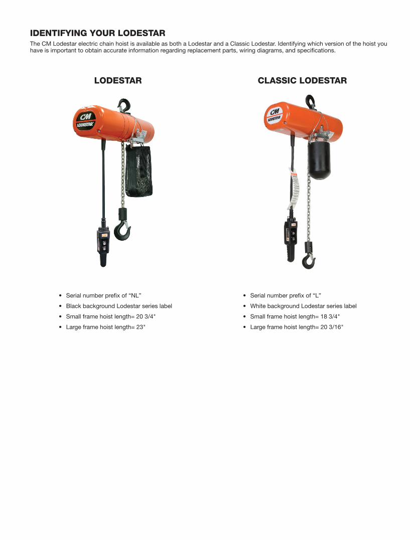
IDENTIFYING YOUR LODESTARThe CM Lodestar electric chain hoist is available as both a Lodestar and a Classic Lodestar. Identifying which version of the hoist you have is important to obtain accurate information regarding replacement parts, wiring diagrams, and specifications.
LODESTAR CLASSIC LODESTAR
• Serial number prefix of “NL”
• Black background Lodestar series label
• Small frame hoist length= 20 3/4"
• Large frame hoist length= 23"
• Serial number prefix of “L”
• White background Lodestar series label
• Small frame hoist length= 18 3/4"
• Large frame hoist length= 20 3/16"
3 192063792 Rev AA April 2019
CM HOIST PARTS AND SERVICES ARE AVAILABLE IN THE UNITED STATES AND CANADA
PARTS FOR YOUR HOIST ARE AVAILABLE FROM YOUR LOCAL AUTHORIZED REPAIR STATION. FOR THE
NAME OF THE NEAREST PARTS OR SERVICE CENTER, VISIT OUR WEB SITE WWW.CMWORKS.COM OR
CALL OUR CUSTOMER SERVICE DEPARTMENT AT 800-888-0985.
AN ELECTRONIC COPY OF THIS MANUAL AND THE CM HOIST PARTS AND SERVICES LIST IS AVAILABLE AT:
LODESTAR
https://www.cmworks.com/Hoists/PoweredHoists/ElectricChainHoist/Lodestar
CLASSIC LODESTAR
https://www.cmworks.com/Hoists/PoweredHoists/
ElectricChainHoist/ClassicLodestar
4 5192063792 Rev AA April 2019
SAFETY PRECAUTIONS
Each Lodestar Electric Hoist is built in accordance with the specifications contained herein and at the time of manufacture complied with our interpretation of applicable sections of the *American Society of Mechanical Engineers Code B30.16 “Overhead Hoists,” the National Electrical Code (ANSI/NFPA 70) and the Occupational Safety and Health Act. Since OSHA states the National Electrical Code applies to all electric hoists, installers are required to provide current overload protection and grounding [on the branch circuit section] in keeping with the code. Check each installation for compliance with the application, operation and maintenance sections of these articles.
The safety laws for elevators, lifting of people and for dumbwaiters specify construction details that are not incorporated into the hoists. For such applications, refer to the requirements of applicable state and local codes, and the American National Safety Code for elevators, dumbwaiters, escalators and moving walks (ASME A17.1). Columbus McKinnon Corporation cannot be responsible for applications other than those for which CM equipment is intended.
*Copies of this standard can be obtained from ASME Order Department, 22 Law Drive, Box 2300, Fairfield, NJ 07007-2300, U.S.A.
THIS SYMBOL POINTS OUT IMPORTANT SAFETY INSTRUCTIONS WHICH IF NOT FOLLOWED COULD ENDANGER THE PERSONAL SAFETY AND/OR PROPERTY OF YOURSELF AND OTHERS. READ AND FOLLOW ALL INSTRUCTIONS IN THIS MANUAL AND ANY PROVIDED WITH THE EQUIPMENT BEFORE ATTEMPTING TO OPERATE YOUR LODESTAR HOIST.
Usage of hoists that do not involve lifting of the load on the lower hook or using hoists in the inverted position without special precaution may
cause an accident resulting in injury and/or property damage
TO AVOID INJURY:
Consult Columbus McKinnon for information concerning using hoists in these applications.
Improper operation of a hoist can create a potentially hazardous situation which, if NOT avoided, could result in death, or serious injury. To avoid such a potentially hazardous situation, the operator shall:
1. NOT operate a damaged, malfunctioning or unusually performing hoist.
2. NOT operate the hoist until you have thoroughly read and understood this Operating, Maintenance and Parts Manual.
3. NOT operate a hoist which has been modified.
4. NOT lift more than rated load for the hoist.
5. NOT use hoist with twisted, kinked, damaged, or worn load chain.
6. NOT use the hoist to lift, support, or transport people.
7. NOT lift loads over people.
8. NOT operate a hoist unless all persons are and remain clear of the supported load.
9. NOT operate unless load is centered under hoist.
10. NOT attempt to lengthen the load chain or repair damaged load chain.
11. Protect the hoist’s load chain from weld splatter or other damaging contaminants.
12. NOT operate hoist when it is restricted from forming a straight line from hook to hook in the direction of loading.
13. NOT use load chain as a sling, or wrap load chain around load.
14. NOT apply the load to the tip of the hook or to the hook latch.
15. NOT apply the load unless load chain is properly seated in the chain wheel(s) or sprocket(s).
16. NOT apply load if bearing prevents equal loading on all load supporting chains.
17. NOT operate beyond the limits of the load chain travel.
18. NOT leave load supported by the hoist unattended unless specific precautions have been taken.
19. NOT allow the load chain or hook to be used as an electrical or welding ground.
20. NOT allow the load chain or hook to be touched by a live welding electrode.
21. NOT remove or obscure the warnings on the hoist.
22. NOT operate a hoist on which the safety placards or decals are missing or illegible.
23. NOT operate a hoist unless it has been securely attached to a suitable support.
24. NOT operate a hoist unless load slings or other approved single attachments are properly sized and seated in the hook saddle.
25. Take up slack carefully - make sure load is balanced and load holding action is secure before continuing.
26. Shut down a hoist that malfunctions or performs unusually and report such malfunction.
27. Make sure hoist limit switches function properly.
28. Warn personnel of an approaching load.
Improper operation of a hoist can create a potentially hazardous situation which, if not avoided, could result in minor or moderate injury. To avoid such a potentially hazardous situation, the operator shall:
1. Maintain a firm footing or be otherwise secured when operating the hoist.
2. Check brake function by tensioning the hoist prior to each lift operation.
3. Use hook latches. Latches are to retain slings, chains, etc. under slack conditions only.
4. Make sure the hook latches are closed and not supporting any parts of the load.
5. Make sure the load is free to move and will clear all obstructions.
6. Avoid swinging the load or hook.
7. Make sure hook travel is in the same direction as shown on the controls.
8. Inspect the hoist regularly, replace damaged or worn parts, and keep appropriate records of maintenance.
9. Use the hoist manufacturer’s recommended parts when repairing the unit.
10. Lubricate load chain per hoist manufacturer’s recommendations.
11. NOT use the hoist load limiting or warning device to measure load.
12. NOT use limit switches as routine operating stops unless allowed by manufacturer. They are emergency devices only.
13. NOT allow your attention to be diverted from operating the hoist.
14. NOT allow the hoist to be subjected to sharp contact with other hoists, structures, or objects through misuse.
15. NOT adjust or repair the hoist unless qualified to perform such adjustments or repairs.

4 5 192063792 Rev AA April 2019
DO NOT PULL AT AN ANGLE. BE SURE HOIST AND LOAD ARE IN A STRAIGHT LINE.
DO NOT USE LOAD CHAIN AS A SLING.
USE HOIST PROPERLYBe sure hoist is solidly held in the uppermost part of the support hook arc.
Be sure hoist and load are in a straight line. Do not pull at an angle.
Be sure load is hooked securely. Do not tip load the hook. Do not load hook latch. Hook latch is to prevent detachment of load under slack chain conditions only.
Do not use load chain as a sling. Such usage damages the chain and lower hook.
Do not operate with hoist head resting against any object. Lift the load gently. Do not jerk it.
DO NOT LIFT PEOPLE OR LOADS OVER PEOPLE
LIFT PROPERLYDo not lift co-workers with a hoist.
Make sure everyone is clear of the load when you lift.
Do not remove or obscure operational warning notices.
MAINTAIN PROPERLYCLEANING
Hoists should be kept clean and free of dust, dirt, moisture, etc., which will in any way affect the operation or safety of the equipment.
LUBRICATION
Chain should be properly lubricated.
AFTER REPAIRS
Carefully operate the hoist before returning it to full service.
HOIST SAFETY IS UP TO YOU...
DO NOT LIFT MORE THAN RATED LOAD.
CHOOSE THE RIGHT HOIST FOR THE JOB...Choose a hoist with the capacity for the job. Know the capacities of your hoists and the weight of your loads. Then match them.
The application, the size and type of load, the attachments to be used and the period of use must also be taken into consideration in selecting the right hoist for the job.
Remember, the hoist was designed to ease our burden and carelessness not only endangers the operator, but in many cases, a valuable load.
DO NOT OPERATE DAMAGED OR MALFUNCTIONING HOIST.
DO NOT OPERATE WITH TWISTED, KINKED, OR DAMAGED CHAIN.
INSPECTAll hoists should be visually inspected before use, in addition to regular, periodic maintenance inspections.
Inspect hoists for operations warning notices and legibility.
Deficiencies should be noted and brought to the attention of supervisors. Be sure defective hoists are tagged and taken out of service until repairs are made.
Under no circumstances should you operate a malfunctioning hoist.
Check for gouged, twisted, distorted links and foreign material. Do not operate hoists with twisted, kinked, or damaged chain links.
Load chain should be properly lubricated.
Hooks that are bent, worn, or whose openings are enlarged beyond normal throat opening should not be used. If latch does not engage throat opening of hook, hoist should be taken out of service.
Chains should be checked for deposits of foreign material which may be carried into the hoist mechanism.
Check brake for evidence of slippage under load.
VIOLATIONS OF ANY OF THE WARNINGS LISTED MAY RESULT IN SERIOUS PERSONAL INJURY TO THE OPERATOR OR NEARBY PERSONNEL BY NATURE OF RELEASED LOAD OR BROKEN HOIST COMPONENTS.

6 7192063792 Rev AA April 2019
TABLE OF CONTENTS Safety Precautions ......................................................................... 4-5
Foreword ........................................................................................... 6
General Information Lodestar Identification ........................................................... 2 Online Resources ................................................................... 3 Specifications ......................................................................... 7 CM Repair/Replacement Policy ............................................. 7 Troubleshooting .................................................................... 28 Electrical Data ...................................................................... 32 Torque Specifications ........................................................... 34
Accessories Hook Suspensions ............................................................... 10 Lug Suspension ................................................................... 10 Latchlok Hooks .................................................................... 10 Chain Container ................................................................... 10
Installation Unpacking Information ......................................................... 11 Installing Suspension ........................................................... 11 Attaching Load Chain........................................................... 12 Lower Hook Block Pin.......................................................... 13 Chain Stop ........................................................................... 13 Cutting Chain ....................................................................... 13 Power Supply and Electrical Connections ........................... 13
Operating Instructions General ................................................................................. 16 Hoist Operating Instruction .................................................. 16 Safety Procedures ................................................................ 16
Inspection Inspection ............................................................................. 17 Preventative Maintenance .................................................... 19 Hook Inspection ................................................................... 20 Load Chain ........................................................................... 20 Removal and Installation ................................................. 21
Ordering Instructions ....................................................................... 22
Maintenance Overload Protection Clutch .................................................. 22 Hoist Lubrication .................................................................. 23 Gear Alignment .................................................................... 23 Electric Brake Adjustment .................................................... 24 Limit Switch Adjustment ...................................................... 25
LIST OF TABLESTable Title ........................................................................... Page 1 Lodestar Electric Chain Hoist Specs ............................ 7-9 2 Voltage Requirements .................................................... 15 3 Extension Cords ............................................................ 15 4 Minimum Frequent Inspections ..................................... 18 5 Minimum Periodic Inspections ...................................... 18 6 Minimum Hook Dimension ............................................. 19 7 Chain Dimensions .......................................................... 20 8 Limit Switches ................................................................ 27 9 Troubleshooting ........................................................ 28-31 10 Electrical Data ........................................................... 32-33 11 Torque Specifications ............................................... 34-35
LIST OF ILLUSTRATIONS Figure Title ............................................................................ Page 1 Hook Suspensions ......................................................... 10 2 Lug Suspensions ........................................................... 10 3 Series 635 Low Headroom Trolley ................................. 10 4 Series 635 Motor Driven Trolley ..................................... 10 5 Latchlok Hook ................................................................ 10 6 Chain Container ............................................................. 10 7 Hook Suspension ........................................................... 11 8 Attaching Load Chain .................................................... 12 9 Contact Block ................................................................ 12 10 Chain Stop ..................................................................... 13 11 Cutting Chain by Nicking ............................................... 13 12 Cutting Chain with a Bolt Cutter .................................... 13 13 Voltage Change Board ................................................... 14 14 Location of Components ............................................... 14 15 Printed Contactor Board ................................................ 14 16 Hook Inspection ............................................................. 19 17 Chain Wear Areas .......................................................... 20 18 Chain Dimensions ......................................................... 20 19 Gaging Load Chain Wear ............................................... 20 20 Chain Embossing ........................................................... 20 21 Non-Circular Gearing ..................................................... 23 22 Limit Switches, Models A-H .......................................... 25 23 Rotatable Limit Switches, Models A-H .......................... 25 24 Limit Switches, Models J-RRT....................................... 25 25 Rotatable Limit Switches, Models J-RRT ...................... 25
FOREWORD This manual contains important information to help you properly install, operate and maintain your hoist for maximum performance, economy and safety.
Please study its contents thoroughly before putting your hoist into operation. By practicing correct operating procedures and by carrying out the recommended preventive maintenance suggestions, you will experience long, dependable and safe service. After you have completely familiarized yourself with the contents of this manual, we recommend that you carefully file it for future reference.
The information herein is directed to the proper installation, use, care and maintenance of the hoist and does not comprise a handbook on the broad subject of rigging.
Rigging can be defined as the process of lifting and moving heavy loads using hoists and other mechanical equipment. Skill acquired through specialized experience and study is essential to safe rigging operations. For rigging information, we recommend consulting a standard textbook on the subject.

6 7 192063792 Rev AA April 2019
GENERAL INFORMATION
SPECIFICATIONS The Lodestar Electric Chain Hoist is a highly versatile materials handling device that can be used to lift loads that are within rated capacity. The mechanical features of these hoists include an alloy steel lift wheel, overload protection clutch, hardened steel chain guides, hardened steel gear train, life-time lubrication, forged steel hooks and lightweight aluminum frame. The electrical features include hoist-duty motor, rugged hoist brake, magnetic reversing contactor and voltage conversion board (dual voltage units). The hoist is available with hook or lug suspensions that are supplied separately. Table 1 summarizes the Lodestar Electric Chain Hoist models and the Series 635 Trolleys available. It should be noted that standard single speed hoists are available with 10 (3M), 15 (4.6M) and 20 (6.1M) foot lifts and the standard lift for two speeds hoists is10 feet. However, hoists with longer lifts are available on a special, per order basis.
SPECIFICATIONS Table 1.a.
Lodestar and Classic Lodestar Electric Chain HoistsSingle Speed 115-1-60
ModelLoad Capacity Lifting Speed
60Hz unitsLifting Speed
50Hz units Chain FallsChain Size Chain Weight per length
of lift
Tonne kg ft/min m/min ft/min m/min in x in mm x mm lb/ft kg/m
A 1/8 125 32 9.8 26.7 8.1 1 .250 x .7445 6.35 x 18.9 0.585 0.87
AA 1/8 125 60 18.3 50.0 15.2 1 .250 x .7445 6.35 x 18.9 0.585 0.87
B 1/4 250 16 4.9 13.3 4.1 1 .250 x .7445 6.35 x 18.9 0.585 0.87
C 1/4 250 32 9.8 26.7 8.1 1 .250 x .7445 6.35 x 18.9 0.585 0.87
E 1/2 500 8 2.4 6.7 2.0 2 .250 x .7445 6.35 x 18.9 1.17 1.74
F 1/2 500 16 4.9 13.3 4.1 1 .250 x .7445 6.35 x 18.9 0.585 0.87
J 1/2 500 32 9.8 26.7 8.1 1 .312 x .8583 7.92 x 21.8 0.94 1.40
H 1 1000 8 2.4 6.7 2.0 2 .250 x .7445 6.35 x 18.9 1.17 1.74
L 1 1000 16 4.9 13.3 4.1 1 .312 x .8583 7.92 x 21.8 0.94 1.40
R 2 2000 8 2.4 6.7 2.0 2 .312 x .8583 7.92 x 21.8 1.88 2.80
RT 3 3000 5.3 1.6 4.4 1.4 3 .312 x .8583 7.92 x 21.8 2.82 4.20
Lodestar and Classic Lodestar Electric Chain HoistsSingle Speed 115-1-60
Model
Lodestar Classic Lodestar
Shortest Distance Between Hooks
*Nominal Power at Hook IP
Rating
Net Weight 10' lift less upper suspension
Shortest Distance Between Hooks
*Nominal Power at Hook IP
Rating
Net Weight 10' lift less upper
suspension
in mm HP kW lb kg in mm HP kW lb kg
A 16.9 429 0.25 0.19
54
68 31 16.9 429 0.25 0.19
54
65 29
AA 16.9 429 0.50 0.37 68 31 16.9 429 0.50 0.37 65 29
B 16.9 429 0.25 0.19 69 31 16.9 429 0.25 0.19 65 29
C 16.9 429 0.50 0.37 68 31 16.9 429 0.50 0.37 65 29
E 21.6 548 0.25 0.19 78 35 21.6 548 0.25 0.19 77 35
F 16.9 429 0.50 0.37 69 31 16.9 429 0.50 0.37 65 29
J 18.1 460 1.00 0.75 126 57 18.1 460 1.00 0.75 114 52
H 21.6 549 0.50 0.37 78 35 21.6 549 0.50 0.37 77 35
L 18.1 460 1.00 0.75 126 57 18.1 460 1.00 0.75 116 52
R 25.8 656 1.00 0.75 151 69 25.8 656 1.00 0.75 142 64
RT 32.1 815 1.00 0.75 170 77 32.1 815 1.00 0.75 160 73
*Power listed is for 60 Hertz units. For 50 Hertz units, power will be 5/6 of those listed.
CM REPAIR/REPLACEMENT POLICY All Columbus McKinnon (CM®) Lodestar Electric Chain Hoists are inspected and per formance tested pr ior to shipment. If any properly maintained hoist develops a performance problem due to a material or workmanship defect, as verified by CM®, repair or replacement of the unit will be made to the original purchaser without charge. This repair/replacement policy applies only to Lodestar Hoists installed, maintained and operated as outlined in this manual, and specifically excludes parts subject to normal wear, abuse, improper installation, improper or inadequate maintenance, hostile environmental effects and unauthorized repairs/modifications.
We reserve the right to change materials or design if, in our opinion, such changes will improve our product. Abuse, repair by an unauthorized person, or use of non-CM replacement parts voids the guarantee and could lead to dangerous operation. For full Terms of Sale, see Sales Order Acknowledgement. Also, refer to the back cover for Limitations of Warranties, Remedies and Damages, and Indemnification and Safe Operation.

8 9192063792 Rev AA April 2019
SPECIFICATIONS (CONT.)Table 1.b.
Lodestar and Classic Lodestar Electric Chain HoistsSingle Speed 230/460-3-60 or 220/380-3-50 or 220/415-3-50
ModelLoad Capacity Lifting Speed
60Hz unitsLifting Speed
50Hz units Chain FallsChain Size Chain Weight per length
of lift
Tonne kg ft/min m/min ft/min m/min in x in mm x mm lb/ft kg/m
A 1/8 125 32 9.8 26.7 8.1 1 .250 x .7445 6.35 x 18.9 0.585 0.87
AA 1/8 125 60 18.3 50.0 15.2 1 .250 x .7445 6.35 x 18.9 0.585 0.87
B 1/4 250 16 4.9 13.3 4.1 1 .250 x .7445 6.35 x 18.9 0.585 0.87
C 1/4 250 32 9.8 26.7 8.1 1 .250 x .7445 6.35 x 18.9 0.585 0.87
E 1/2 500 8 2.4 6.7 2.0 2 .250 x .7445 6.35 x 18.9 1.17 1.74
F 1/2 500 16 4.9 13.3 4.1 1 .250 x .7445 6.35 x 18.9 0.585 0.87
J 1/2 500 32 9.8 26.7 8.1 1 .312 x .8583 7.92 x 21.8 0.94 1.40
JJ 1/2 500 64 19.5 53.3 16.3 1 .312 x .8583 7.92 x 21.8 0.94 1.40
H 1 1000 8 2.4 6.7 2.0 2 .250 x .7445 6.35 x 18.9 1.17 1.74
L 1 1000 16 4.9 13.3 4.1 1 .312 x .8583 7.92 x 21.8 0.94 1.40
LL 1 1000 32 9.8 26.7 8.1 1 .312 x .8583 7.92 x 21.8 0.94 1.40
R 2 2000 8 2.4 6.7 2.0 2 .312 x .8583 7.92 x 21.8 1.88 2.80
RR 2 2000 16 4.9 13.3 4.1 2 .312 x .8583 7.92 x 21.8 1.88 2.80
RRS 2 2000 16 4.9 13.3 4.1 1 .394 x 1.18 10 x 30 1.45 2.16
RT 3 3000 5.3 1.6 4.4 1.4 3 .312 x .8583 7.92 x 21.8 2.82 4.20
RRT 3 3000 10.7 3.3 8.9 2.7 3 .312 x .8583 7.92 x 21.8 1.88 2.80
Lodestar and Classic Lodestar Electric Chain HoistsSingle Speed 230/460-3-60 or 220/380-3-50 or 220/415-3-50
Model
Lodestar Classic Lodestar
Shortest Distance Between Hooks
*Nominal Power at Hook IP
Rating
Net Weight 10' lift less upper suspension
Shortest Distance Between Hooks
*Nominal Power at Hook IP
Rating
Net Weight 10' lift less upper suspension
in mm HP kW lb kg in mm HP kW lb kg
A 16.9 429 0.25 0.19
54
65 29 16.9 429 0.25 0.19
54
62 28
AA 16.9 429 0.50 0.37 65 30 16.9 429 0.50 0.37 62 28
B 16.9 429 0.25 0.19 66 30 16.9 429 0.25 0.19 62 28
C 16.9 429 0.50 0.37 65 29 16.9 429 0.50 0.37 62 28
E 21.6 548 0.25 0.19 75 34 21.6 548 0.25 0.19 74 34
F 16.9 429 0.50 0.37 66 30 16.9 429 0.50 0.37 62 28
J 18.1 460 1.00 0.75 120 54 18.1 460 1.00 0.75 108 49
JJ 18.1 460 2.00 1.49 128 58 18.1 460 2.00 1.49 117 53
H 21.6 548 0.50 0.37 75 34 21.6 548 0.50 0.37 74 34
L 18.1 460 1.00 0.75 120 54 18.1 460 1.00 0.75 110 50
LL 18.1 460 2.00 1.49 128 58 18.1 460 2.00 1.49 118 53
R 25.8 656 1.00 0.75 145 66 25.8 656 1.00 0.75 136 62
RR 25.8 656 2.00 1.49 153 70 25.8 656 2.00 1.49 144 65
RRS 24.8 630 2.00 1.49 153 69 N/A N/A N/A N/A N/A N/A
RT 32.1 815 1.00 0.75 164 74 32.1 815 1.00 0.75 154 70
RRT 32.1 815 2.00 1.49 172 78 32.1 815 2.00 1.49 162 74
*Power listed is for 60 Hertz units. For 50 Hertz units, power will be 5/6 of those listed.

8 9 192063792 Rev AA April 2019
SPECIFICATIONS (CONT.)Table 1.c.
Lodestar and Classic Lodestar Electric Chain Hoists Two Speed 230-3-60 or 460-3-60 or 575-3-60 or 220-3-50 or 380-3-50 or 415-3-50 or 550-3-50
ModelLoad Capacity Lifting Speed
60Hz unitsLifting Speed
50Hz units Chain FallsChain Size Chain Weight per length
of lift
Tonne kg ft/min m/min ft/min m/min in x in mm x mm lb/ft kg/m
A-2 1/8 125 10.7/32 3.3/9.8 8.9/26.7 2.7/8.1 1 .250 x .7445 6.35 x 18.9 0.585 0.87
AA-2 1/8 125 20/60 6.1/18.3 16.7/50 5.1/15.2 1 .250 x .7445 6.35 x 18.9 0.585 0.87
B-2 1/4 250 5.3/16 1.6/4.9 4.4/13.3 1.4/4.1 1 .250 x .7445 6.35 x 18.9 0.585 0.87
C-2 1/4 250 10.7/32 3.3/9.8 8.9/26.7 2.7/8.1 1 .250 x .7445 6.35 x 18.9 0.585 0.87
E-2 1/2 500 2.7/8 0.8/2.4 2.2/6.7 0.7/2 2 .250 x .7445 6.35 x 18.9 1.17 1.74
F-2 1/2 500 5.3/16 1.6/4.9 4.4/13.3 1.4/4.1 1 .250 x .7445 6.35 x 18.9 0.585 0.87
J-2 1/2 500 10.7/32 3.3/9.8 8.9/26.7 2.7/8.1 1 .312 x .8583 7.92 x 21.8 0.94 1.40
JJ-2 1/2 500 21.3/64 6.5/19.5 17.8/53.3 5.4/16.3 1 .312 x .8583 7.92 x 21.8 0.94 1.40
H-2 1 1000 2.7/8 0.8/2.4 2.2/6.7 0.7/2 2 .250 x .7445 6.35 x 18.9 1.17 1.74
L-2 1 1000 5.3/16 1.6/4.9 4.4/13.3 1.4/4.1 1 .312 x .8583 7.92 x 21.8 0.94 1.40
LL-2 1 1000 10.7/32 3.3/9.8 8.9/26.7 2.7/8.1 1 .312 x .8583 7.92 x 21.8 0.94 1.40
R-2 2 2000 2.7/8 0.8/2.4 2.2/6.7 0.7/2 2 .312 x .8583 7.92 x 21.8 1.88 2.80
RR-2 2 2000 5.3/16 1.6/4.9 4.4/13.3 1.4/4.1 2 .312 x .8583 7.92 x 21.8 1.88 2.80
RT-2 3 3000 1.8/5.3 0.5/1.6 1.5/4.4 0.5/1.4 3 .312 x .8583 7.92 x 21.8 2.82 4.20
RRT-2 3 3000 3.6/10.7 1.1/3.3 3/8.9 0.9/2.7 3 .312 x .8583 7.92 x 21.8 1.88 2.80
Lodestar and Classic Lodestar Electric Chain HoistsTwo Speed 230-3-60 or 460-3-60 or 575-3-60 or 220-3-50 or 380-3-50 or 415-3-50 or 550-3-50
Model
Lodestar Classic Lodestar
Shortest Distance Between Hooks
*Nominal Power at Hook IP
Rating
Net Weight 10' lift less upper suspension
Shortest Distance Between Hooks
*Nominal Power at Hook IP
Rating
Net Weight 10' lift less upper suspension
in mm HP kW lb kg in mm HP kW lb kg
A-2 16.9 429 0.25 0.19
54
70 32 16.9 429 0.25 0.19
54
67 30
AA-2 16.9 429 0.50 0.37 70 32 16.9 429 0.50 0.37 67 30
B-2 16.9 429 0.25 0.19 71 32 16.9 429 0.25 0.19 67 30
C-2 16.9 429 0.50 0.37 70 32 16.9 429 0.50 0.37 67 30
E-2 21.6 548 0.25 0.19 80 36 21.6 548 0.25 0.19 79 36
F-2 16.9 429 0.50 0.37 71 32 16.9 429 0.50 0.37 67 30
J-2 18.1 460 1.00 0.75 132 60 18.1 460 1.00 0.75 120 54
JJ-2 18.1 460 2.00 1.49 136 62 18.1 460 2.00 1.49 125 57
H-2 21.6 548 0.50 0.37 80 36 21.6 548 0.50 0.37 79 36
L -2 18.1 460 1.00 0.75 132 60 18.1 460 1.00 0.75 122 55
LL-2 18.1 460 2.00 1.49 136 62 18.1 460 2.00 1.49 126 57
R-2 25.8 656 1.00 0.75 157 71 25.8 656 1.00 0.75 148 67
RR-2 25.8 656 2.00 1.49 161 73 25.8 656 2.00 1.49 152 69
RT-2 32.1 815 1.00 0.75 176 80 32.1 815 1.00 0.75 166 75
RRT-2 32.1 815 2.00 1.49 180 82 32.1 815 2.00 1.49 170 77
*Power listed is for 60 Hertz units. For 50 Hertz units, power will be 5/6 of those listed.
10 11192063792 Rev AA April 2019
ACCESORIES
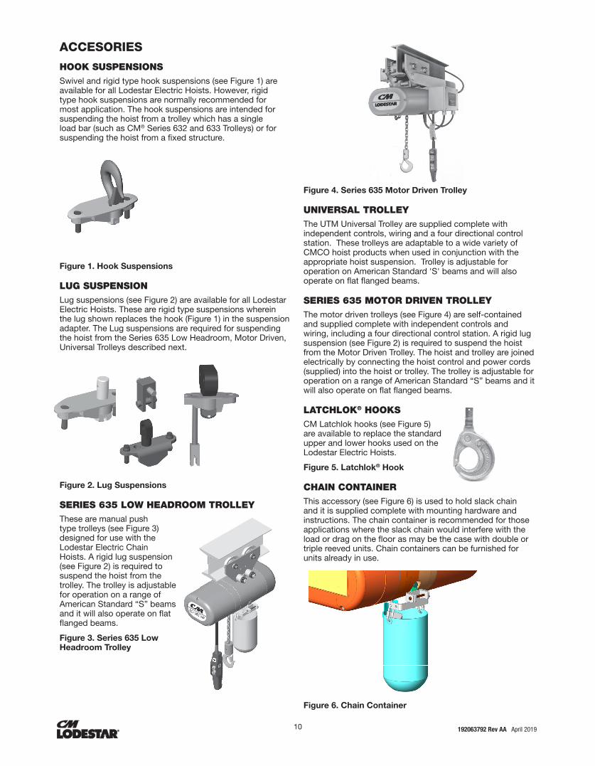
HOOK SUSPENSIONSSwivel and rigid type hook suspensions (see Figure 1) are available for all Lodestar Electric Hoists. However, rigid type hook suspensions are normally recommended for most application. The hook suspensions are intended for suspending the hoist from a trolley which has a single load bar (such as CM® Series 632 and 633 Trolleys) or for suspending the hoist from a fixed structure.
Figure 1. Hook Suspensions
LUG SUSPENSION Lug suspensions (see Figure 2) are available for all Lodestar Electric Hoists. These are rigid type suspensions wherein the lug shown replaces the hook (Figure 1) in the suspension adapter. The Lug suspensions are required for suspending the hoist from the Series 635 Low Headroom, Motor Driven, Universal Trolleys described next.
Figure 2. Lug Suspensions
SERIES 635 LOW HEADROOM TROLLEY These are manual push type trolleys (see Figure 3) designed for use with the Lodestar Electric Chain Hoists. A rigid lug suspension (see Figure 2) is required to suspend the hoist from the trolley. The trolley is adjustable for operation on a range of American Standard “S” beams and it will also operate on flat flanged beams.
Figure 3. Series 635 Low Headroom Trolley
Figure 4. Series 635 Motor Driven Trolley
UNIVERSAL TROLLEY The UTM Universal Trolley are supplied complete with independent controls, wiring and a four directional control station. These trolleys are adaptable to a wide variety of CMCO hoist products when used in conjunction with the appropriate hoist suspension. Trolley is adjustable for operation on American Standard 'S' beams and will also operate on flat flanged beams.
SERIES 635 MOTOR DRIVEN TROLLEY The motor driven trolleys (see Figure 4) are self-contained and supplied complete with independent controls and wiring, including a four directional control station. A rigid lug suspension (see Figure 2) is required to suspend the hoist from the Motor Driven Trolley. The hoist and trolley are joined electrically by connecting the hoist control and power cords (supplied) into the hoist or trolley. The trolley is adjustable for operation on a range of American Standard “S” beams and it will also operate on flat flanged beams.
LATCHLOK® HOOKS CM Latchlok hooks (see Figure 5) are available to replace the standard upper and lower hooks used on the Lodestar Electric Hoists.
Figure 5. Latchlok® Hook
CHAIN CONTAINER This accessory (see Figure 6) is used to hold slack chain and it is supplied complete with mounting hardware and instructions. The chain container is recommended for those applications where the slack chain would interfere with the load or drag on the floor as may be the case with double or triple reeved units. Chain containers can be furnished for units already in use.
Figure 6. Chain Container

10 11 192063792 Rev AA April 2019
INSTALLATION
UNPACKING INFORMATION When received, the hoist should be carefully inspected for damage which may have occurred during shipment or handling. Check the hoist frame for dents or cracks, the external cords for damaged or cut insulation, the control station for cut or damaged enclosure, and inspect the load chain for nicks and gouges. If shipping damage has occurred, refer to the packing list envelope on the carton for claim procedure.
Before installing the hoist, make sure that the power supply to which it will be connected is the same as that shown on the nameplate located on the side of the hoist.
NOTE: See Electrical Installation instructions
INSTALLING THE SUSPENSION
A. Single Reeved Units:
For Models A,B,C,F, J, JJ, L, & LL:
Remove the hook suspension and (2) suspension screws from the packaging. Place the suspension assembly into the recess on top of the hoist so that the adaptor body follows the contour of the hoist. Insert the suspension screws through the holes in the adapter and hand thread these into the self-locking nuts enclosed in the hoist.
Securely tighten the screws to the recommended seating torque (see Table 11) using a 12 point socket: 3/8" for Models A, B, C, & F and 1/2" for Models J-LL.
For Model RRS:
Remove the hook suspension, screw and locknut from the packaging. Slide the suspension assembly into the channel in the top of the hoist. Insert the locknut into the hex recess on the side of the suspension riser, insert the screw through opposite side and hand thread the screw into the self-locking nut.
Securely tighten the screw to the recommended torque (see table 11), using a 3/16" hex bit socket.
Use of impact tools (electric or pneumatic) may cause premature failure of attaching hardware.
B. Double Reeved Units:
Remove the hook suspension,(2) suspension screws, (1) dead end pin, (1) washer, and (1) cotter pin from the packaging. It should be noted that the suspension includes a dead end bolt and block for supporting the dead end of the load chain as shown in Figure 7. If not previously assembled, assemble the dead end bolt and block through the suspension adapter as shown in Figure 7.
Place the suspension assembly into the recess on top of the hoist. The dead end block should project through the bottom of the hoist with the pin hole and slot aligned to the underside of the hoist as shown in Figure 8. If these are not aligned as shown, lift the head of the bolt from the hex recess in the adapter and turn the bolt and block assembly and reseat the bolt head to obtain the proper alignment. Do not change the position of the dead end block on the bolt to attain this alignment.
Check the position of the pin hole in the dead end block to
make sure it has not been disturbed from its factory setting. The distance from the top of the pin hole to the bottom of the hoist should not exceed 1/4" (6.35mm) for Models E,E-2, H, H-2 and 7/16" (11.11mm) for Models R, R-2, RR, RR-2. If the distance is not correct, adjust the position of the dead end block to obtain the proper distance (see fig. 7)
Now, insert the suspension screws through the holes in the adapter and hand thread these into the self-locking nuts enclosed in the hoist frame. Securely tighten the screws to the recommended seating torque (see Table 11) using a 12 point socket: 3/8" for Models E & H and 1/2" for Models R & RR.
The dead end of the load chain is temporarily positioned ( a few links from the end) by a wire tie. Do not remove this tie before attaching the chain to the dead end block. (See Fig. 8)
Figure 7. Hook Suspension
C. Triple Reeved Units:
These hoists have a sheave hanger which is loosely connected to the top of the frame by a thin metal plate for shipping purposes. To attach the suspension, support the sheave hanger from the underside of the hoist and remove the nut and seat from the sheave stud. Remove and discard the shipping plate and retain the sheave stud nut and seat since they will be reused later.
Remove the suspension assembly from the carton and the two suspension screws. Place the suspension assembly over the sheave stud and into the recess on top of the hoist. Insert the suspension screws through the holes in the suspension adapter and hand thread these into the self-locking nut enclosed in the hoist. Securely tighten the screws to the recommended seating torque (see Table 11) using a 12 point, 1/2" socket.
After the suspension assembly is installed, secure the sheave stud to the suspension adapter using the round slotted nut and seat that were formerly used to attach the shipping plate to top of the hoist frame. Place the seat over the stud with the flat side down and then rotate the seat so that there is clearance between the seat and the suspension lug or hook. Assemble the nut to the stud and turn the nut by hand until the nut seats in the seat and the sheave hanger is snug in the frame. Then back off the nut until the hole in the stud is in line with one of the slots in the nut. Using a hammer, drive the retaining pin (packed with the suspension assembly) into the hole in the sheave stud until the end of the pin is flush with the edge of the nut.
12 13192063792 Rev AA April 2019
Using other than CM supplied high strength suspension screws to attach the suspension adapter to the hoist may cause the screws to
break and allow the hoist and load to fall.
TO AVOID INJURY:
Use only the CM supplied suspension screws to attach the suspension to the hoist and hand torque these screws to the
recommended seating torque as specified in table 11. DO NOT apply any type of lubricant to the threads of these screws.
Lubricating the threads will reduce the effort to seat the screws and as a result, tightening the screws to the above recommended torque may break the screw,damage the suspension adapter, strip
the nuts and/or damage the hoist frame.
SUSPENSION BOLT SHOULD BE REPLACED ANY TIME THE SUSPENSION IS REMOVED FROM THE HOIST
3
2
4
7
11
9
8
101
5
6
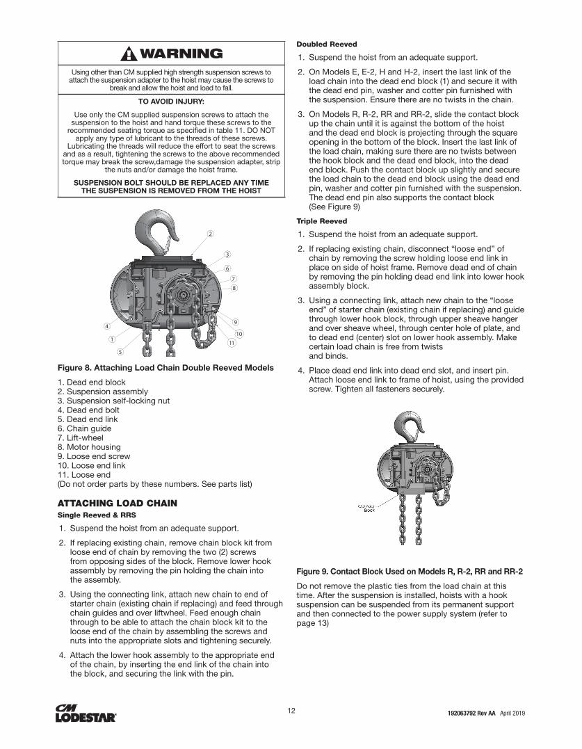
Figure 8. Attaching Load Chain Double Reeved Models
1. Dead end block 2. Suspension assembly 3. Suspension self-locking nut 4. Dead end bolt 5. Dead end link 6. Chain guide 7. Lift-wheel 8. Motor housing 9. Loose end screw 10. Loose end link 11. Loose end (Do not order parts by these numbers. See parts list)
ATTACHING LOAD CHAINSingle Reeved & RRS
1. Suspend the hoist from an adequate support.
2. If replacing existing chain, remove chain block kit from loose end of chain by removing the two (2) screws from opposing sides of the block. Remove lower hook assembly by removing the pin holding the chain into the assembly.
3. Using the connecting link, attach new chain to end of starter chain (existing chain if replacing) and feed through chain guides and over liftwheel. Feed enough chain through to be able to attach the chain block kit to the loose end of the chain by assembling the screws and nuts into the appropriate slots and tightening securely.
4. Attach the lower hook assembly to the appropriate end of the chain, by inserting the end link of the chain into the block, and securing the link with the pin.
Doubled Reeved
1. Suspend the hoist from an adequate support.
2. On Models E, E-2, H and H-2, insert the last link of the load chain into the dead end block (1) and secure it with the dead end pin, washer and cotter pin furnished with the suspension. Ensure there are no twists in the chain.
3. On Models R, R-2, RR and RR-2, slide the contact block up the chain until it is against the bottom of the hoist and the dead end block is projecting through the square opening in the bottom of the block. Insert the last link of the load chain, making sure there are no twists between the hook block and the dead end block, into the dead end block. Push the contact block up slightly and secure the load chain to the dead end block using the dead end pin, washer and cotter pin furnished with the suspension. The dead end pin also supports the contact block (See Figure 9)
Triple Reeved
1. Suspend the hoist from an adequate support.
2. If replacing existing chain, disconnect “loose end” of chain by removing the screw holding loose end link in place on side of hoist frame. Remove dead end of chain by removing the pin holding dead end link into lower hook assembly block.
3. Using a connecting link, attach new chain to the “loose end” of starter chain (existing chain if replacing) and guide through lower hook block, through upper sheave hanger and over sheave wheel, through center hole of plate, and to dead end (center) slot on lower hook assembly. Make certain load chain is free from twists and binds.
4. Place dead end link into dead end slot, and insert pin. Attach loose end link to frame of hoist, using the provided screw. Tighten all fasteners securely.
Figure 9. Contact Block Used on Models R, R-2, RR and RR-2
Do not remove the plastic ties from the load chain at this time. After the suspension is installed, hoists with a hook suspension can be suspended from its permanent support and then connected to the power supply system (refer to page 13)

12 13 192063792 Rev AA April 2019
CHECKING FOR TWIST IN LOAD CHAINDouble Reeved The best way to check for this condition is to run the lower hook, without a load, up to within about 2 feet (.61 meters) of hoist. If the dead end of the chain has been properly installed, a twist can occur only if the lower hook block has been capsized between the strands of chain. Reverse capsize to remove twist.
Triple Reeved On these models, the load chain is dead ended on top of the lower hook block. If the chain has been properly installed, the only way a twist can occur is if the lower hook block has been capsized between the strands of chain. If this has occurred, two strands of chain will be wrapped around each other and to remove this, reverse the capsize.
LOWER HOOK BLOCK PINWhen removing or installing the lower hook pin, care must be taken so as to prevent damaging the pin and/or hook block. These pins are tapered groove pins and as a result, they can only be removed in one direction. To remove the pin, a V-Block, drift and hammer (or slow acting press) are required. The drift should be the same diameter as the pin (5/16” diameter (7.94mm) for Models A, A-2, AA. AA-2, B, B-2, C. C-2, F. F-2 and 3/8” (9.52mm) diameter for Models J, J-2. L, L-2, LL, LL-2 and (7/16" diameter (11.11mm) for Model RRS1 and it should be placed on the small end of the pin. The small end of the pin is the end opposite the end on which the 3 grooves are visible. Place the hook block in the V-Block and drive the pin out using the drift and a hammer or slow acting press.
To re-install the pin, the parts must be arranged the same as they were when the pin was removed. To do this, use the small end of the pin as a gage. First check the holes in the hook block body and determine which hole is the largest. Place the hook body in the V-Block with the larger hole on top. Next, check each end of the hole in the lower hook chain block and determine which end is the largest. Place the chain in the slot of the chain block and insert the chain block, with the large hole on top, into the hook block body. Align the holes in the hook block body with the hole in the chain block and insert the small end of the pin in the hole. Push the pin in by hand until it stops and then use a hammer or slow acting press to drive the pin into position so that the end of the pin is flush with the outside surface of the hook block body.
Use of improper lower hook chain block pin as well as improper installation of this pin can cause the pin to break and allow the
load to fall.
TO AVOID INJURY: Use only CM supplied, special high strength lower hook chain
block pin to attach the chain to the lower hook block and install the pin as directed above.
CHAIN STOP INSTALLATIONPlace polyurethane stop block over loose end of chain and slide past desired spot that the chain stop is to be located. Place one half of chain stop on chain. Then place other half on top of the first half of chain stop. (Note: be sure that the half circle cut out side of one stop block half is aligned with hex cut out side.) Place one (1) nut into hex cutout insert one (1) screw with one (1) lock washer through hole opposite nut and loosely tighten. Repeat for second connection. Tighten both screw connections to ensure that
they do not come loose.
Hex Cut Out
Loose End Of Chain
To Liftwheel
Polyurethane Stop BlockHalf-Circle Cut Out
Figure 10. Chain Stop
CUTTING CHAINCM® Load chain is hardened and it is difficult to cut. The following methods are recommended when cutting a length of new chain from stock or cutting off worn chain.
1. Use a grinder and nick the link on both sides (Figure 11), then secure the link in a vise and break off with a hammer.
2. Use a 177.8 mm (7 inches) minimum diameter by 3.175 mm (1/8 inch) thick abrasive wheel (or type recommended by wheel supplier) that will clear adjacent links.
3. Use a bolt cutter (Figure 12) similar to the H.K. Porter No. 0590MTC with special cutter jaws for cutting hardened chain (25.4mm-1 inch) long cutting edge.
Figure 11. Cutting Chain by Nicking
Figure 12. Cutting Chain with a Bolt Cutter
Cutting Chain Can Produce Flying Particles.
TO AVOID INJURY: • Wear Eye Protection.
• Provide A shield Over Chain to Prevent Flying Particles.
POWER SUPPLY AND ELECTRICAL CONNECTIONS The hoist should be connected to a branch circuit which complies with the requirements of the National Electrical Code and applicable local codes.
It is recommended, especially for a single phase hoist with

14 15192063792 Rev AA April 2019
a (1) horsepower motor (.75 Kilowatts), that a line with adequate capacity be run directly from the power supply to the hoist to prevent problems with low voltage and circuit overloads.
For grounding of the hoist, the power cord includes a grounding conductor (green yellow, G-Y). Before connecting the hoist to the power supply, check that the power to be used agrees with the position of voltage change plug on the voltage change board. The nominal hoist voltage rating corresponding to the voltage range given on hoist identification plate is
THREE PHASE HOIST Unless ordered on a special basis, all single speed/dual voltage (230/460-3-60, 220/380-3-50 and 220/415-3-50) hoists are factory arranged to operate on 460-3-60 (or 380-3- 50 or 415-3-50).
Voltage Change Board
A voltage change board is provided to easily and quickly change from 460 to 230 (or 380 to 220 or 415 to 220) volt operation. The voltage change board shown in Figure 13 is located in the hoist as shown in Figure 14. The voltage change board is color coded to indicate high and low voltage connections. Connecting the 9 and 12 pin plugs into the “Red” voltage change board receptacles will connect the hoist for high voltage (380-3-50, 415-3-50 or 460-3-60). To change the hoist voltage to low voltage (208-3- 60, 220-3-50 or 230-3-60) simply remove the 9 and 12 pin plugs from the “Red” receptacles and insert same into the “White” receptacles located on the voltage change board. Be sure to make a notation of the new hoist voltage on the tag attached to the power cord.
Figure 13. Voltage Change Board
Figure 14. Location of Components Both the voltage conversion board and PCB assembly are located under back frame cover (1) for Models A-H and under motor housing cover (2) for Models J-RRT.
Printed Contactor Board
Some dual-voltage Lodestar hoists are equipped with a printed circuit board assembly shown below in Figure 15. The board has two-12 pin receptacles that correspond to either high or low voltage operation. To change the hoist operating voltage from high voltage (380-3-50, 415-3-50, or 460-3-60) to low voltage (208-3-60, 220-3-50, or 230-3-60) simply remove the 12-pin plug from the receptacle labeled “460V Motor” and insert the plug in the receptacle labeled “230V Motor.” Be sure to make a notation of the new hoist voltage on the tag attached to the power cord.
Figure 15. Printed Contactor Board
POWER PHASING Since the motor in a three phase hoist can rotate in either direction, depending on the manner in which it is connected to the power supply, the direction of hook movement must be checked prior to each usage.
NOTE: Serious damage can result if the hook is run to the upper or lower limit of travel with the hook operating in a direction opposite to that indicated by the control station. Therefore, proceed as follows:
4. Make temporary connections at the power supply.
5. Operate (UP) control momentarily. If hook raises, connections are correct and can be made permanent.
6. If hook lowers, it is necessary to change direction by inter-changing the Grey lead and the Black lead of hoist power supply. Under no circumstances should the internal wiring of the control device or hoist be changed to reverse hook direction. The wiring is inspected and tested before leaving the factory.
Do not force the hoist's overload protection clutch to compensate for improperly adjusted limit switches or reverse voltage phasing.

14 15 192063792 Rev AA April 2019
CHECKING FOR ADEQUATE VOLTAGE AT HOIST The hoist must be supplied with adequate electrical power in order to operate properly. For proper operation, the voltage, (measured at the hoist end of the standard power cord with the hoist operating in the, up direction with full load) must be as indicated in the table below.
Table 2. Voltage Requirements
Nominal Voltage Source Voltage Range Minimum Starting Voltage
115-1-60 110-120 99
230-1-60 220-240 198
230-3-60 208-240 188
460-3-60 440-480 396
575-3-60 550-600 495
220-3-50 200-240 171
380-3-50 350-410 365
415-3-50 380-440 342
550-3-50 525-575 495
SIGNS OF INADEQUATE ELECTRICAL POWER (LOW VOLTAGE) ARE: • Noisy hoist operations due to brake and/or
contactor chattering.
• Dimming of lights or slowing of motors connected to the same circuit.
• Heating of the hoist motor and other internal components as well as heating of the wires and connectors in the circuit feeding the hoists.
• Failure of the hoist to lift the load due to motor stalling.
• Blowing of fuses or tripping of circuit breakers.
Failure to properly ground the hoist presents the danger of electric shock.
TO AVOID INJURY:
Permanently ground the hoist as instructed in this manual.
To avoid these low voltage problems, the hoist must be connected to an electrical power supply system that complies with the National Electrical Code and applicable local codes. This system must also provide overcurrent protection (slow blow fuses or inverse-time type circuit breakers) and provisions for grounding the hoist.
Low voltage may also be caused by using an undersized cord and/or connectors to supply power to the hoist. Table 3 should be used to determine the size wires in the extension cord in order to minimize the voltage drop between the power source and the hoist.
Table 3. Extension Cords
Length of Extension Cord
Single Phase Hoists Three Phase Hoist
Minimum Wire Size Minimum Wire Size
Up to 50 Feet #14 AWG #16 AWG
80 FEET (24.4 M) #12 AWG #16 AWG
120 FEET (36.7 M) #10 AWG #14 AWG
200 FEET (61.0 M) Contact Factory #14 AWG
For runs beyond 200 Feet contact factory.
Failure to provide a proper power supply system for the hoist may cause hoist damage and offers the potential for a fire.
TO AVOID INJURY:
Provide each hoist with a 20 amp, minimum, overcurrent protected power supply system per the National Electrical Code
and applicable local codes as instructed in this manual.
Remember, operation with low voltage can void the CM repair/replacement policy. When in doubt about any of the electrical requirements, consult a qualified electrician.
Working in or near exposed energized electrical equipment presents the danger of electric shock.
TO AVOID INJURY:
DISCONNECT POWER AND LOCKOUT/TAGOUT DISCONNECTING MEANS BEFORE REMOVING COVER
OR SERVICING THIS EQUIPMENT.
CHECKING LIMIT SWITCH OPERATION IF HOIST IS EQUIPPED With hoists that are equipped with an adjustable screw limit switch, the limit switch will automatically stop the hook at any predetermined point when either hoisting or lowering.
Allowing the hook block to run into the bottom of the hoist when raising a load or allowing the chain to become taut between the loose end screw and the frame when lowering a load may break
the chain and allow the load to drop.
Do not allow the hook block to contact the bottom of the hoist or the loose end chain to become taut.
Operate hoist over the entire length of its rated lift, checking upper and lower limit switches for correct operation as follows:
7. Press (UP) control and raise the lower hook until top of hook block is about one foot (305 mm) below the hoist.
8. Cautiously continue raising the hook until the upper limit switch stops the upward motion. The upper limit switch is set at the factory to stop the hook block 3 inches (76.2 mm) from bottom of the hoist on all units with standard 10 foot (3m) lift except Models AA and AA-2. Factory setting is 6 inches (152.4 mm) for these models and for all other models equipped with chain for lifts longer than 10 feet (3m).
9. If adjustment is necessary, see page 25.
10. Press (DOWN) control and cautiously lower hook until lower limit switch stops the downward motion with 7-11 chain links (depending on hoist model) between the loose end link and the hoist entry. If adjustment is necessary, see page 25.
NOTE: If the hoist is equipped with a chain container/bag, reset the upper and lower limit switches as indicated on page 25.
Under no condition should the hook block or load be permitted to come in contact with the chain container/bag. If contact is made, the function of the chain container can be interfered with and its fasterners imperiled.

16 17192063792 Rev AA April 2019
NOTE: When chain bag is filled to capacity the bag must be no more than 75% filled.
CONTROL CORD Unless ordered on a special basis, the hoist is supplied with a control cord that will position the control station approximately 4 feet above the lower hook when it is at the lower limit of the lift. If this places the control station too close to the floor, a “control cord alteration kit” (contact factory for part number) can be obtained from CM for shortening the length of the control cord.
Tying knots or loops to shorten the drop of the control station will make the strain relief ineffective and the internal conductors of the
cord may break
TO AVOID INJURY:
Shorten the control cord using the control cord alteration kit and the instructions provided with the kit.
OPERATING INSTRUCTIONS
GENERAL 1. The hoist's overload protection clutch is designed to slip
on an excessive overload. An overload is indicated when the hoist will not raise the load. Also, some clutching noise may be heard if the hoist is loaded beyond rated capacity. Should this occur, immediately release the (UP) control to stop the operation of the hoist. At this point, the load should be reduced to the rated hoist capacity or the hoist should be replaced with one of the proper capacity. When the excessive load is removed, normal hoist operation is automatically restored. CAUTION: The clutch is susceptible to overheating and wear when slipped for extended periods. Under no circumstance should the clutch be allowed to slip for more than a few seconds. It is not recommended for use in any application where there is a possibility of adding to an already suspended load to the point of overload. This includes dumbwaiter (*see below) installations, containers that are loaded in mid-air, etc. (*) Refer to limitations on Page 4 concerning dumbwaiter applications. Also, if a Cassic Lodestar Hoist with a Protector™ is used a unusual extremes of ambient temperatures, above 150ºF (106ºC) or below 15ºF (0ºC), changes in lubricant properties may permit the hoist to raise larger loads than under normal operating conditions and present possibility of damage or injury.
2. All hoists are equipped with an adjustable screw limit switch, which automatically stops the hook at any predetermined point when either hoisting or lowering.
3. The control station used on two speed hoists is similar to single speed unit, except that either of two definite speeds may be selected by the operator in both hoisting and lowering. Each control when partially depressed provide SLOW speed and when fully depressed gives FAST speed. Partial release of control returns hoist to slow speed, while complete release allows hoist to stop. Rated lifting speeds are shown on hoist identification plate. SLOW speed is intended as a means of carefully
controlling or “spotting” the load, although the hoist may be operated solely at this speed if desired. It is not necessary to operate in the SLOW speed position as the hoist will pick up a capacity load at FAST speed from a standing start. In other words, it is not necessary to hesitate at the slow position when moving control from STOP to FAST position or vice versa.
4. If material being handled must be immersed in water, pickling baths, any liquid, dusty or loose solids, use a sling chain of ample length so that the hook is always above the surface. Bearings in the hook block are shielded only against ordinary atmospheric conditions.
HOIST 1. Before picking up a load, check to see that the hoist is
directly overhead.
2. WHEN APPLYING A LOAD, IT SHOULD BE DIRECTLY UNDER HOIST OR TROLLEY. AVOID OFF CENTER LOADING OF ANY KIND.
3. Take up a slack load chain carefully and start load easily to avoid shock and jerking of hoist load chain. If there is any evidence of overloading, immediately lower the load and remove the excess load.
4. DO NOT allow the load to swing or twist while hoisting.
5. DO NOT allow the load to bear against the hook latch.HOIST WITH LOW HEADROOM TROLLEY
This unit should be moved by pushing on the suspended load or by pulling the empty hook. However, the unit can also be moved by pulling on the control station since an internal steel cable extends the length of the control cord and is anchored to the hoist and to the control station.
HOIST WITH MOTOR DRIVEN TROLLEY This unit should be moved by operating the controls marked (Forward) and (Reverse) in control station. Unless altered by the erector, depressing (Forward) control will move the hoist toward motor housing end. Anticipate the stopping point and allow trolley to coast to a smooth stop. Reversing or “plugging” to stop trolley causes overheating of motor and swaying of load.
SAFE OPERATING INSTRUCTIONS AND PROCEDURES For safety precautions and a list of Do’s and Do Not’s for safe operation of hoists, refer to page 4.
1. Permit only competent personnel to operate unit.
2. When preparing to lift a load, be sure that the attachments to the hook are firmly seated in hook saddle. Avoid off center loading of any kind, especially loading on the point of hook.
3. DO NOT allow the load to bear against the hook latch. The latch is to help maintain the hook in position while the chain is slack before taking up slack chain.
Allowing the load to bear against the hook latch and/or hook tip can result in loss of load.
TO AVOID INJURY:
Do not allow the load and/or attachments to bear against the hook latch and/or hook tip. Apply load to hook bowl or
saddle only.
16 17 192063792 Rev AA April 2019
4. DO NOT wrap the load chain around the load and hook onto itself as a choker chain.
Doing this will result in:
a. The loss of the swivel effect of the hook which could result in twisted chain and a jammed lift wheel.
b. The upper limit switch, if so equipped, is by-passed and the load could hit the hoist.
c. The chain could be damaged at the hook.
5. Before lifting load, check for twists in the load chain. On double and triple reeved units, a twist can occur if the lower hook block has been capsized between the strands of chain. Reverse the capsize to remove twist.
6. Stand clear of all loads and avoid moving a load over the heads of other personnel. Warn personnel of your intentions to move a load in their area.
7. DO NOT leave the load suspended in the air unattended.
8. DO NOT use this or any other overhead materials handling equipment for lifting persons.
9. DO NOT load hoist beyond the rated capacity shown on ID plate. When in doubt, use the next larger capacity CM Lodestar Hoist.
10. Warn personnel of your intention to lift a load in the area. Tie off the load with auxiliary chains or cables before access to the area beneath the load is permitted.
11. Take up a slack load chain carefully and start load easily to avoid shock and jerking of hoist load chain. If there is any evidence of overloading, immediately lower the load and remove the excess load.
12. When lifting, raise the load only enough to clear the floor or support and check to be sure that the attachments to the hook and load are firmly seated. Continue lift only after you are assured the load is free of all obstructions.
13. DO NOT allow the load to swing or twist while hoisting.
14. Never operate the hoist when flammable materials or vapors are present. Electrical devices produce arcs or sparks that can cause a fire or explosion.
15. STAY ALERT! Watch what you are doing and use common sense. Do not use the hoist when you are tired, distracted or under the influence of drugs, alcohol or
medication causing diminished control.
INSPECTION To maintain continuous and satisfactory operation, a regular inspection procedure must be initiated to replace worn or damaged parts before they become unsafe. Inspection intervals must be determined by the individual application and are based on the type of service to which the hoist will be subjected.
The type of service to which the hoist is subjected can be classified as “Normal”, “Heavy”, or “Severe”.
Normal Service:
Involves operation with randomly distributed loads within the rated load limit, or uniform loads less than 65 percent of rated load for not more than 25 percent of the time.
Heavy Service:
Involves operating the hoist within the rated load limit which exceeds normal service.
Severe Service:
Normal or heavy service with abnormal operating conditions or constant exposure to the elements of nature.
Two classes of inspection - frequent and periodic - must be performed.
Frequent Inspections:
These inspections are visual examinations by the operator or other designated personnel. Records of such inspections are not required. The frequent inspections are to be performed monthly for normal service, weekly to monthly for heavy service, and daily to weekly for severe service, and they should include those items listed in Table 4.
Periodic Inspections:
These inspections are visual inspections of external conditions by an appointed person. Records of periodic inspections are to be kept for continuing evaluation of the condition of the hoist.
Periodic inspections are to be performed yearly for normal service, semi-annually for heavy service and quarterly for severe service, and they are to include those items listed in Table 5.
CAUTION: Any deficiencies found during inspections are to be corrected before the hoist is returned to service. Also, the external conditions may show the need for disassembly to permit a more detailed inspection, which, in turn, may require the use of nondestructive type testing.

18 19192063792 Rev AA April 2019
Table 4. Minimum Frequent Inspections
TYPE OF SERVICE ITEM
Normal Heavy Severe
Mon
thly
Wee
kly
to M
onth
ly
Dai
ly t
o W
eekl
y
a) Brake for evidence of slippage.
b) Control functions for proper operation.
c) Hooks for damage, cracks, twists, excessive throat opening, latch engagement and latch operation - see page 18.
d) Load chain for adequate lubrication, as well as for signs of wear, damaged links or foreign matter - see page 20.
e) Load chain for proper reeving and twists.
Table 5. Minimum Periodic Inspections
TYPE OF SERVICE ITEM
Normal Heavy Severe a) All items listed in Table 4 for frequent inspections.
Year
ly
Eve
ry 6
Mon
ths
Eve
ry 3
Mon
ths
b) External evidence of loose screws, bolts or nuts.
c) External evidence of worn, corroded, cracked or distorted hook block, suspension screws,gears, bearings and dead end block and chain pin.
d) External evidence of damage to hook retaining nut and pin. Also check the upper suspension adapter making sure it is fully seated in the hoist frame and that both screws are tight.
e) External evidence of damage or excessive wear of the liftwheel and hook block sheave chain pockets. Widening and deepening of the pockets may cause the chain to lift-up in the pocket and result in binding between liftwheel and chain guides or between the sheave and hook block. Also, check the chain guide for wear or burring where the chain enters the hoist. Severely worn or damaged parts should be replaced.
f) External evidence of excessive wear of brake parts, and AC brake adjustment - see page 22.
g) External evidence of pitting or any deterioration of contactor contacts. Check the operation of the control station making sure the buttons operate freely and do not stick in either position.
h) Inspect the electrical cords and cables and control station enclosure for damaged insulation.
i) Inspect trolley trackwheels for external wear on tread and flange and for wear on internal bearing surfaces as evidenced by a looseness on the stud. Suspension components for damage, cracks, wear and operation. Also check suspension adapter screws for proper tightness - see page 11.
j) Inspect the loose end link, loose end screw and dead end block on double reeved units. Replace worn or distorted parts.
k) Inspect the suspension lug or hook for excess free play or rotation. Replace worn parts as evidenced by excess free play or rotation.
l) Inspect for signs of lubricant leaks at the gasket between the gear housing and back frame. tighten screws holding back frame to gear housing. If leak persists, repack housing and gears with grease and install a new gasket.
m) On the Models RT, RT-2, RRT and RRT-2:
1. Inspect shackle and lug pins for wear. Replace if worn.
2. Check dead end screw in lower hook black for wear and tightness*.
3. Check shackle pin for proper seating in groove of load bracket.
4. Inspect cloverleaf plate on bottom of sheave hanger for wear or burring. Replace if worn.
5. Inspect sheave stud nut and seat for wear. Replace if worn or damaged.
* When tightening the special, dead end socket head screw, it should be held firmly in place and torqued from the nut end only to avoid damage to the screw and/or dead end chain link (Refer to step J on page 45).

18 19 192063792 Rev AA April 2019
PREVENTATIVE MAINTENANCE In addition to the above inspection procedure, a preventive maintenance program should be established to prolong the useful life of the hoist and maintain its reliability and continued safe use. The program should include the periodic and frequent inspections with particular attention being paid to the lubrication of the various components using the recommended lubricants (Refer to the hoist information provided at the link on page 3 of this manual).
SUSPENSION INSPECTION CRITERIABRACKETS - Replace any brackets found to be cracked or distorted.
BOLTS - If the suspension is removed for any reason, including inspection, the suspension bolts should be replaced.
NYLON THREAD LOCKING NUTS - It is not necessary to replace the nylon thread locking nuts each time the suspension bolts are replaced as long as new bolts with the locking patch are being used. It is recommend that the nylon thread locking nuts are replaced each time the hoist is torn down to allow these nuts to be replaced.
HOOK REMOVE CRITERIA
Based on ASME B30-10 Hooks shall be removed from service if damage such as the following is visible and shall only be returned to service when approved by a qualified person:
a. Missing or illegible rated load identification or illegible hook manufacturers’ identification or secondary manufacturer’s identification.
b. Excessive pitting or corrosion.
c. Cracks, nicks, or gouges.
d. Wear--any wear exceeding 10% of the original section dimension of the hook or its load pin.
e. Deformation--any visibly apparent bend or twist from the plane of the unbent hook.
f. Throat opening-any distortion causing an increase in the throat opening of 5% not to exceed ¼” (6mm).
g. Inability to lock - any self-locking hook that does no lock.
h. Inoperative latch any damaged latch or malfunctioning latch that does not close the hook’s throat.
i. Thread wear, damage, or corrosion.
j. Evidence of excessive heat exposure or unauthorized welding.
k. Evidence of unauthorized alterations such as drilling, machining, grinding, or other modifications.
"A" MAX.
A
A
"B" MIN
"A" MAX
B
B
"B" MIN
Section A-A Section B-B
Figure 16. Hook Inspection
Table 6. Hook Dimensions
ModelsLatch Type Hook Latchlok® Hook
"A" Max "B" Min "A" Max "B" Min
A, A-2, AA, AA-2, B, B-2, C, C-2, F
AND F-2
1.19" (30.2mm)
.91" (23.1mm)
1.48" (37.7mm)
.75" (18.8mm)
E, E-2, H, H-2, J, J-2, JJ, JJ-2, L, L-2, LL AND
LL-2
1.31" (33.3mm)
1.08" (27.5mm)
1.48" (37.7mm)
.75" (18.8mm)
R,R-2, RR, RR-2AND RRS
1.50" (38.1 mm)
1.43" (36.2mm)
1.92" (48.8mm)
.94" (23.9mm)
RT, RT-2, RRT AND RRT-2
1.50" (38.1 mm)
1.43" (36.2mm)
2.50" (63.5mm)
1.19" (23.9mm)

20 21192063792 Rev AA April 2019
INSPECTING THE LOAD CHAIN:The chain must be inspected at regular intervals, with a minimum of once annually. As the frequency of use increases, the time intervals between inspections must be reduced. During inspection, the chain link must be examined along their entire length, including the hidden parts. If the lifting equipment is frequently used with a constant lifting distance or in other words the switch from upward to downward often takes place in the same area, a particularly thorough inspection and lubrication is required in that area. Worn chain can also be an indication of worn hoist components. For this reason, the heist's chain guides, hook blocks and liftwheel (sprocket) should be examined for wear and replaced as necessary when replacing chain.
1. Check to see if chain is dirty or poorly lubricated.
2. Clean the chain with a non-caustic/non-acid type solvent and make a link by link inspection for wear or cracks in the links, twisted or deformed links. Chain with any one of these defects must be replaced.
3. Slack the portion of the chain that normally passes over the lift-wheel (sprocket) or idler sprocket on multi-reeved hoist. Examine the chain links for wear ( see figure 17). If the wire diameter anywhere on the link measures less than 90% of the nominal wire diameter, the chain must be replaced.
Figure 17. Chain Wear Areas
4. Based upon ASME B30.16, chainlinks should also be
checked for elongation. Select an unworn, unstretched length of the chain (at the slack end for example). Suspend the chain vertically under tension and using a knife blade caliper type gauge, measure the outside length of any convenient number of links, 11 is recommended. Measure the same number of links in the used sections and calculate the percentage in increased length. The chain should be replaced if the length of the used portion is more than 1.5% longer than the unused protion of the chain. Also, if the pitch of any individual link has elongated by more than 5%, the chain should be replaced.
Figure 18. Chain Dimensions
Table 7. Chain Dimensions
Models P D
A thru H-2 .745" (18.9mm) .250" (6.3mm)
J thru RRT-2 .858" (21.8 mm) .312" (7.9mm)
RRS 1.18" (30.0 mm) .394" (10.0 mm)
Figure 19. Gaging Load Chain Wear
Figure 20. Chain Embossing
Use only Star (*) grade load chain and original replacement parts. Use of other chain and parts may be dangerous and voids factory warranty.
IMPORTANT: Do not use replaced chain for other purposes such as lifting or pulling. Load chain may break suddenly without visual deformation. For this reason, cut replaced chain into short lengths to prevent use after disposal.
Use of commercial or other manufacturer’s chain and parts to repair CM hoists may cause load loss.
TO AVOID INJURY:
Use only CM supplied replacement load chain and parts. Chain and parts may look alike, but CM chain and parts are made of specific material or processed to achieve specific properties.

20 21 192063792 Rev AA April 2019
REMOVAL AND INSTALLATION OF LOAD CHAIN
Improper installation (reeving) of the load chain can result in a dropped load.
TO AVOID INJURY/DAMAGE: • Verify use of proper size and type of
hoist load chain for specific hoist.
• Install load chain properly as indicated below.
NOTE: When installing load chain in Models E, H, R, RR, E-2, H-2, R-2 and RR-2 by either of the “starter chain” methods, two loose end connecting links must be used. Hoist load chain can be installed by any one of several methods.
USE OF COMMERCIAL OR OTHER MANUFACTURER’S CHAIN AND PARTS TO REPAIR CM HOISTS MAY CAUSE LOAD LOSS.
TO AVOID INJURY: Use only CM supplied replacement load chain and parts. Chain and parts may look alike, but CM chain and parts are made of specific material or processed to achieve specific properties.
The first method is recommended when replacing severely worn load chain and requires disassembling the hoist. Method 2 does not require hoist disassembly, where as Method 3 requires only partial disassembly.
Method #1
a. Disconnect hoist from power supply.
b. Remove back frame cover and disengage the limit switch guide plate from the traveling nuts, see page 25.
c. Detach loose end of load chain from hoist frame, see Figure 8. Also, on single reeved models, detach the lower hook block from the load chain. On double reeved models E, H, R, & RR unfasten the dead end side of load chain. On triple reeved Models RT, RRT, RT-2 and RRT-2, detach the load chain from the lower hook block.
d. Continue to disassemble the hoist and inspect the liftwheel, chain guides, motor housing and gear housing which if worn or damaged may cause premature failure of the new chain. Parts can be easily identified by referring to pages Parts List section of table of contents.
e. If the liftwheel pockets, in particular the ends, are worn or scored, replace liftwheel. If chain guides and housing are worn, cracked or damaged these parts should also be replaced.
f. Reassemble hoist with the new load chain inserted over the liftwheel. Position chain with the weld on up standing links away from liftwheel and leave only one foot of chain hanging free on loose end side. Make sure the last chain link is an upstanding link. On double reeved models, make sure that the new load chain has an even number of links. On triple reeved models, make sure that the new chain has an odd number of links. This will prevent twist in chain. To simplify handling when reassembling the hoist, a short undamaged piece of the old chain may be used as a “starter chain”. Position this piece of chain in exactly the same manner as explained above for the “new chain”, and complete the reassembly of the hoist.
g. Attach the loose end link to chain and connect it to the hoist frame with the loose end screw, washer and lock washer, see Figure 8.
BE CERTAIN THERE IS NO TWIST.
NOTE: RRS USES CHAIN BLOCK ON LOOSE END AND CHAIN IS NOT SECURED TO THE HOIST.
CAUTION: For double reeved models, be sure to disconnect one of the loose end links from the load chain before attaching it to the hoist.
h. For single reeved models, attach the hook block to load chain and proceed to step K.
i. For double reeved models, run the hoist (UP) until only 3 feet (.9 m) in chain remains on dead end side. This will minimize the chance of introducing a twist between hook block and hoist. Allow the chain to hang free to remove twists.
j. Using a wire as a starter, insert the chain, flat link first, into lower hook block (upstanding links will have weld toward sheave) and pull through. Insert last link into slot in dead end block making certain that no twist exists in the reeving at any point. Assemble dead end pin, washer and cotter pin as shown in Figure 7.
k. Adjust limit switches as described in Table 8, page 27. If the new chain is longer than the old, check to be sure limit switch will allow for new length of lift. In the event maximum adjustment does not allow entire length of lift, check with CM® for modification if necessary.
l. For triple reeved models, run the hoist (UP) until only 4 feet (1.2 m) of chain remains on the dead end side. This will minimize the chance of introducing a twist between the hook block and hoist. Allow the chain to hang free to remove twists. Using a wire as a starter, insert the chain, upstanding link first, into lower hook block (upstanding links will have welds toward sheave) and pull through. Using a wire as a starter, insert the chain, upstanding link first, into the outboard cloverleaf of the hanger. Make sure there are no twists between the hook block and then pull the chain through. In the sheave hanger, the up standing links will have the welds toward the sheaves. Run the chain down to the hook block and making sure there are no twists between the sheave hanger and the hook block, insert the end of the chain into the recess in the top of the hook block. Slide the dead end screw, with flat sides vertical, through the hole in the top of the hook block. Place the lock washer and nut on the threaded end of the dead end screw. Use an Allen wrench to hold the head of the dead end screw stationary and rotate the nut to tighten. To properly tighten the nut, apply a torque of 45 (61N•m) to 55 pound feet (74.6 N•m) while holding the head of the dead end screw stationary. Also, when tightening this dead end screw, it should be held firmly in position and torqued from the nut end to avoid damaging the screw and/or chain.
Do not allow hook block to hit hoist or allow load chain to become taut between loose end screw and frame or else serious damage
will result. If hook block should inadvertently hit the hoist-the hoist frames, load chain and hook block should be inspected for
damage before further use.
Method #2
Treat the old load chain in hoist as a “starter chain” and proceed with steps from Method #1, a, b, c and h thru k. If a starter chain is used, the loose end link (two links required for double reeved models) can serve as a temporary coupling link to connect together the starter chain in the hoist and

22 23192063792 Rev AA April 2019
the new load chain to be installed. Then, under power, reeve the new load chain through the liftwheel area, replacing the starter chain in unit. Run enough chain through to attach loose end link to hoist frame.
Method #3
a. First proceed with Steps 1a, b & c from Method #1.
b. Then, carefully run the load chain out of the hoist.
c. Disconnect hoist from power supply.
d. Remove the electric brake assembly.
e. Rotate the brake hub by hand, at the same time feeding the load chain into and through liftwheel area with hoist upside down or using a wire to pull the load chain up onto the liftwheel as explained in Method #1 step 1f.
f. Refer to Method #1 steps g thru j above to complete the installation.
Note: Check Limit Switch Operation after Installing Load Chain
ORDERING INSTRUCTIONSThe following information must accompany all correspondence orders for replacement parts:
1. Hoist Model Number from identification plate.
2. Serial number of the hoist stamped below identification plate.
3. Voltage, phase, Hertz from the identification plate.
4. Length of lift.
5. Part number of part from parts list.
6. Number of parts required.
7. Part name from parts list. If trolley replacement parts are ordered, also include the type and capacity of trolley.
NOTE: When ordering replacement parts, it is recommended that consideration be given to the need for also ordering such items as gaskets, fasteners, insulators, etc. These items may be damaged or lost during disassembly or just unfit for future use because of deterioration from age or service.
Using “Commercial” or other manufacturer’s parts to repair the CM Lodestar Hoists may cause load loss.
TO AVOID INJURY: Use only CM supplied replacement parts. Parts may
look alike but CM parts are made of specific materials or processed to achieve specific properties.
MAINTENANCEThe overload protection clutch should operate for the normal life of the hoist without service. The device has been calibrated at the factory for a specific model of hoist and is not adjustable or interchangeable with other models. For proper overload protection, be sure before installing a Load-limiter or Protector™ that it is correct for the unit.
LOAD-LIMITER (LODESTAR)
Models Load-Limiter Part Number
Load-Limiter ID (marked on
Load-limiter)
A,A-2,B,B-2, E, E-2 C00000240 240
AA,AA-2, C, C-2, F, F-2,H, H-2
C00000241 241
J, J-2, L, L-2, R, R-2,RT, RT-2
C00000242 242
JJ. JJ-2, LL, LL-2, RRRR-2, RRS, RRT, RRT-2
C00000243 243
The lubricants used in and recommended for the Lodestar Hoist may contain hazardous materials that mandate specific handling
and disposal procedures.
TO AVOID CONTACT AND CONTAMINATION:
Handle and dispose of lubricants only as directed in applicable material safety data sheets and in accordance with applicable
local, state and federal regulations.
PROTECTOR™ (CLASSIC LODESTAR)
Models Protector™ Part Number
Protector™ ID (marked on edge of spring washer)
A, A-2, B, B-2, E, E-2 28694 White
AA, AA-2 28693 Light Blue
C, C-2, F, F-2, H, H-2 28695 Orange
J, J-2 36668 Red
JJ, JJ-2 36669 White-Green
L, L-2, R, R-2, RT, RT-2 36670 Green
LL, LL-2, RR, RR-2, RRT, RRT-2
36671 Yellow
Removing the snap ring on the Protector assembly will allow the parts to spring apart.
TO AVOID INJURY: Do not attempt to disassemble the Protector.
Caution: the Protector™ is to be used with Century Lubricants HB-11, #3 great. Use of any other grease will damage Protector™ parts or cause improper operation.
Caution: Never degrease or attempt to disassemble the Protector™. Degreasing may damage parts or cause erratic, inconsistent operation. If the Protector™ has been degreased, it must be replaced by a factory calibrated device.

22 23 192063792 Rev AA April 2019
HOIST LUBRICATION GEARS
NOTE: To assure extra long life and top performance, be sure to lubricate the various parts of the Lodestar Hoist using the lubricants specified. If desired, these lubricants may be purchased from CM. Refer to the hoist information provided at the link on pg. 3 of this manual.
The gearbox is packed at assembly with grease and should not need to be renewed unless the gears have been removed from the housing and degreased.
If the gears are removed from the housing, wipe the excess grease off with a soft cloth and degrease the gears and housings. Upon reassembly, add grease to gears and housing.
Models A to H hoists require 7 fl. oz. of grease. Model J to RRT excluding RRS hoists require 15 fl. oz. Of grease.
For model RRS hoist: fully coat gear teeth and pack gear box, using a total of 22 fluid ounces of grease
1. Apply 7 ounces of grease on the final gear stage, prior to installing the intermediate frame
2. Apply 15 ounces of grease on the 1st 2 gear stages, prior to installing the back frame.
Also, coat the spline on the end of the drive shaft with a Molydisulphide lubricant such as “Super Herculon”.
• The limit switch gears are of molded polymer and require no lubrication.
• Apply a light film of machine oil to the limit switch shaft threads at least once a year.
BEARINGS
• All bearings and bushings, except the lower hook thrust bearing, are pre-lubricated and require no lubrication. The lower hook thrust bearing should be lubricated at least once a month.
CHAIN GUIDES, LIFTWHEEL AND LOWER SHEAVE WHEEL
• When the hoist is disassembled for inspection and/or repair, the chain guides, lower sheave wheel (on double chain units) and liftwheel must be lubricated with Lubriplate Bar and Chain Oil 10-R (Fiske Bros. Refining Co. or equivalent) prior to reassembly. The lubricant must be applied in sufficient quantity to obtain natural runoff and full coverage of these parts.
LOAD CHAIN
A small amount of lubricant will greatly increase the life of load chain. Do not allow the chain to run dry.
Keep it clean and lubricate at regular intervals with Lubriplate Bar and Chain Oil 10-R (Fiske Bros. Refining Co.) or equal lubricant. Normally, weekly lubrication and cleaning is satisfactory, but under hot and dirty conditions, it may be necessary to clean the chain at least once a day and lubricate it several times between cleanings.
When lubricating the chain, apply sufficient lubricant to obtain natural run-off and full coverage, especially in the interlink area.
Used motor oils contain known carcinogenic materials
TO AVOID HEALTH PROBLEMS: Never use used motor oils as a chain lubricant.
Only use Lubriplate Bar and Chain Oil 10-R as a lubricant for the load chain.
GEAR ALIGNMENT (CLASSIC LODESTAR ONLY)Models JJ, LL, RR, JJ-2, LL-2, RR-2, RRT and RRT-2 have a special Liftwheel Gear and Intermediate Pinion. If the gear train in these hoists is disassembled, the following steps must be observed in order to properly orient the three parts when reassembling:
1. Assemble liftwheel gear to liftwheel
NOTE: These parts have their splines keyed in such a way that they will go together only one way. See Figure 21.
2. To install the intermediate pinion, align the arrows that are stamped on the pinion and liftwheel gear so they point toward each other.
3. Check operation of gear train by rotating the pinion four (4) complete revolutions; liftwheel gear will turn one (1) complete revolution and the arrows will again be aligned as shown. If the arrows do not align or there is binding between the gear teeth, repeat the above steps.
4. For gearing lubrication instructions, see previous section.
Liftwheel
Intermediate
Missing Tooth in
Spline
Liftwheel Gear
Pinion
Liftwheel Spline
in Liftwheel GearMissing Tooth Space
Arrows Must BeAligned AsShown
Figure 21. Non-Circular Gearing
TROLLEY LUBRICATION See appropriate trolley manual.
EXTERIOR FINISHThe exterior surfaces of the hoist and trolleys have a durable, scratch resistant baked powder coating. Normally, the exterior surfaces can be cleaned by wiping with a cloth. However, if the finish is damaged, compatible touch-up paint can be purchased from CM. Refer to the hoist information provided at the link on pg. 3 of this manual.

24 25192063792 Rev AA April 2019
TEMPERATURE RATINGNormal ambient operating temperature, unless otherwise specified, range from 0º f (-17ºc) to 150º f (60ºc). Contact factory for ambient temperature solutions outside this stated range.
SOLID STATE REVERSE SWITCH (115-1-60/230-1-60 Units Only)
Above an ambient temperature of 104°F. (40° C.), the frequency of hoist operation should be limited to avoid overheating the solid state reverse switch. Even at temperatures less than 104° F. (40° C.), high duty cycle, frequent starting or reversing, excessive inching, jogging or plugging may overheat the solid state reverse switch. Overheating the switch will cause it to malfunction, and this in turn will overheat the motor and/or damage the solid state reverse switch.
If allowed to cool, the solid state switch will return to normal operation. However, before returning the hoist to service, the following procedure should be used to determine if the switch has been damaged.
1. De-energize the power system supplying the hoist and remove the solid state reverse switch.
2. Connect the solid state reverse switch to a 115-1-60/230-1-60 light circuit as shown below.
3. Close the switch to energize the 115-1-60/230-1-60 power supply. The light bulb will illuminate if the solid state reverse switch is not damaged. If the bulb fails to illuminate, the switch is damaged and must be replaced.
4. Turn the 115-1-60/230-1-60 power off and remove the solid state reverse switch from the test circuit.
Reinstall the solid state reverse switch in the hoist and re-connect it using the wiring diagram supplied with the hoist. Re-energize the power system supplying the hoist and test for proper operation. Also, ventilate the space around the hoist and/or reduce duty cycle, excessive starting, excessive plugging to reduce future malfunctions of the solid state reverse due to overheating.
BRAKE ADJUSTMENTS DC ELECTRIC BRAKE ASSEMBLY
The correct air gap between field and armature is .008 in (0.2 mm) for all models. The DC brake is not adjustable. As the friction material wears, the brake gap increases. If the maximum air gap is reached, a new friction disc/rotor should be installed.
AC ELECTRIC BRAKE ASSEMBLY
The correct air gap between armature and field, when brake is not energized, is 0.025 inch (.635 mm) and need not be adjusted until the gap reaches 0.045 inches (1.14 mm). When checking brake gap, always reset to 0.025 inch (.0635 mm).
To adjust the brake, proceed as follows:
1. Disconnect hoist from power supply.
2. Remove back frame cover, see Figure 14.
3. Before adjusting the gap:
a. Back off the stud nuts and examine friction linings and friction surfaces for excessive wear, (min. thickness, .188 inches (4.78 mm)), scoring or warpage.
b. Check shading coils to be sure they are in place and not broken. A missing or broken shading coil will cause the brake to be noisy when hoist is operated. Any of these symptoms indicate the need for replacement of parts.
4. Turn adjusting nuts clockwise gaging the air gap at both ends.
Replace cover, reconnect the power and check operation.

24 25 192063792 Rev AA April 2019
LIMIT SWITCH ADJUSTMENTSIf limit switch operation has been checked as described on page 15 and is not operating correctly or is not automatically stopping the hook at a desired position, proceed as follows:
1. Disconnect hoist from power supply.
2. Remove back frame cover, see Figure 14.
3. The identification of upper and lower limit switches are indicated on the fiber insulator.
4. Loosen the 2 screws or spring back the rotatable guide to disengage the travel nut
Figure 22. Limit Switches, Models A–H
1. Limit switch sub-assy
2. Limit switch shaft
3. Travelling nuts
4. Guide plate
5. Screws
Figure 23. Rotatable Limit Switches, Models A–H
SETTING UPPER LIMIT SWITCH After completing steps 1 thru 4
5. Refer to table 8 -The "A" Dimensions given are the minimum distance that should be set between the top at hook block and the bottom of the hoist.
CAUTION: THE “A” DIMENSIONS SHOWN IN TABLE 8 ARE THE MINIMUM ALLOWED FOR SAFE OPERATION AND SHOULD NOT BE REDUCED.
6. Reconnect hoist to power supply.
7. Run hook to the desired upper position,cautiously operating the hoist without a load.
8. Disconnect hoist from power supply.
9. Moving one travel nut toward the other increases hook travel and away from the other decreases the travel. . Now, turn the nut nearest the switch indicated as the “ UPPER LIMIT SWITCH” until it just breaks the limit switch contacts, cautious not to allow the movement of the other travel nut, if previously set. An audible click will be heard as the switch opens. Continue to rotate the nut toward the switch an additional one full tooth.
Figure 24. Limit Switches, Models J–RRT
1. Limit switch sub-assy
2. Limit switch shaft
3. Traveling nuts
4. Guide plate
5. Screws
Figure 25. Rotatable Limit Switches, Models J–RRT
10. Securely reposition the guide plate in the slot
11. Reconnect hoist to power supply and check the stopping point of hook by first lowering the hook about 2 feet (61 cm), then raise the hook by jogging cautiously until the upper limit switch stops upward motion. The stopping point of hook should be the desired upper position. If not, repeat the above instructions.
12. Double check setting by lowering the hook about 2 feet (61 cm) and then run the hook into the upper limit with (UP) control held depressed.
2
3
5
5
1
5
1
3
4
2

26 27192063792 Rev AA April 2019
13. Fine adjustment of the upper limit setting may be obtained by inverting the stationary guide plate in Step 10. (Not available with the rotatable guide plate.) The offset on the plate gives adjustments equivalent to 1/2 notch, see Table 8 for the “Hook Travel Per Notch of Limit Switch Nut”. When inverting the plate, it may be necessary to use the notch adjacent to the one used in the preliminary setting.
SETTING LOWER LIMIT SWITCH After completing steps 1 thru 4
5. Refer to Table 8 -The“B”dimensions given are the minimum length of loose end chain left on the non-load side of the lift wheel when the hook is positioned at the lowest allowable hook position.
CAUTION: THE “B” DIMENSIONS SHOWN IN TABLE 8 ARE THE MINIMUM ALLOWED FOR SAFE OPERATIONS AND SHOULD NOT BE REDUCED.
6. Reconnect hoist to power supply.
7. Run hook to the desired lower position, cautiously operating the hoist without a load.
8. Disconnect hoist from power supply.
9. Moving one travel nut toward the other increases hook travel and away from the other decreases hook travel. Now, turn the nut nearest the switch indicated as the “LOWER LIMIT SWITCH” until it just breaks the limit switch contacts, cautious not to allow the movement of the other travel nut if previously set. An audible click will be heard as the switch opens. Continue to rotate the nut toward the switch an additional one full tooth.
10. Securely reposition the guide plate in the slot.
11. Reconnect hoist to power supply and check the stopping point of hook by first raising the hook about 2 feet (61 cm) then lower the hook by jogging cautiously until the lower limit switch stops downward motion. The stopping point of the hook should be the desired lower position, if not repeat the above instructions.
12. Double check setting by raising the hook about 2 feet (61 cm) and then run the hook into the lower limit with (DOWN) control held depressed.
13. Fine adjustment of the lower limit setting may be obtained by inverting the stationary guide plate in Step 10. (Not available with the rotatable guide plate). The plate offset on the plate gives adjustments equivalent to 1/2 notch, see Table 8 for the “Hook Travel per Notch of Limit Switch Nut”. When inverting the plate, it may be necessary to use the notch adjacent to the one used in the preliminary setting.
CONVERTING LIMIT SWITCH GUIDES 1. Disconnect the hoist from the power supply system.
2. Refer to the exploded views and remove the back frame. cover from the hoist. Remove and discard the limit switch guide plate - retaining the 2 screws.
3. Refer to Figure 22 and 24 and assemble the limit switch guide plate to the limit switch bracket. Secure using the 2 screws.
TESTING Before using, all altered, repaired or used hoists that have not
been operated for the previous 12 months shall be tested by the user for proper operation. First test the unit without a load and then with a light load of 22.7 kg. (50 pounds) times the number of load supporting parts of load chain to be sure that the hoist operates properly and that the brake holds the load when the
control is released. Next test with a load of *125% of rated capacity. In addition, hoists in which load sustaining parts have
been replaced should be tested with *125% of rated capacity by or under the direction of an appointed person and written report
prepared for record purposes. After this test, check that the Load-limiter functions.
*If Load-limiter prevents lifting of a load of 125% of rated capacity, reduce load to rated capacity and continue test.
NOTE: For additional information on inspection and testing, refer to Code B30.16 “Overhead Hoists” obtainable from ASME Order Department, 22 Law Drive, Box 2300, Fairfield, NJ 07007-2300, U.S.A.

26 27 192063792 Rev AA April 2019
Table 8b. Limit Switches
Model
Hook Travel, per Notch A (minimum distance between top of hook block and bottom of hoist) B (minimum length of
loose end chain)
mm in mm in
A, A-2, C, C-2 52.8 2.08 38.1 1.50 6 links
AA, AA-2 98.8 3.89 50.8 2.00 6 links
B, B-2, F, F-2 26.9 1.06 38.1 1.50 6 links
E, E-2, H, H-2 13.5 0.53 44.45 1.75 6 links
L, L-2, J, J-2 30.5 1.20 38.1 1.50 8 links
JJ, JJ-2, LL, LL-2 116.8 4.60 63.5 2.50 8 links
R, R-2 15.2 0.60 63.5 2.50 8 links
RR, RR-2 29.7 1.17 63.5 2.50 8 links
RT, RT-2 10.2 0.40 63.5 2.50 8 links
RRT, RRT-T 19.8 0.78 63.5 2.50 8 links
RRS 30.0 1.18 63.5 2.50 2.50 in
Table 8a. Limit Switches
Model
Hook Travel w/ 44 T.P.I. Shaft (Standard) Hook Travel w/ 56 T.P.I. Shaft (Standard) Hook Travel w/ 64 T.P.I. Shaft (Standard)
Max Length of Lift Max Length of Lift Max Length of Lift
m ft m ft m ft
A, A-2, C, C-2 63 206 80 262 91 299
AA, AA-2 117 385 150 491 171 561
B, B-2, F, F-2 32 105 41 133 46 152
E, E-2, H, H-2 16 52 20 67 23 76
L, L-2, J, J-2 39 127 49 162 56 185
JJ, JJ-2, LL, LL-2 76 250 97 318 111 363
R, R-2 20 64 25 81 28 93
RR, RR-2 38 124 48 158 55 181
RT, RT-2 13 42 16 54 19 62
RRT, RRT-T 25 83 32 106 37 121
RRS 38 125 48 159 55 182

28 29192063792 Rev AA April 2019
TROUBLE PROBABLE CASE REMEDY
1. Hook does not respond to the control station or control device
A.) No voltage at hoist-main line or branch circuit switch open; branch line fuse blown or circuit breaker tripped.
A.) Close switch, replace fuse or reset breaker.
B.) Phase failure (single phasing, three phase unit only)-open circuit, grounded or faulty connection in one line of supply system, hoist wiring, reversing contactor, motor leads or windings.
B.) Check for electrical continuity and repair or replace defective part.
C.) Upper or lower limit switch has opened the control circuit.
C.) Press the “other” control and the hook should respond. Adjust limit switches as described on page 25.
D.) Open control circuit-open or shorted winding in transformer, reversing contactor coil or loose connection or broken wire in circuit;mechanical binding in contactor control station contacts not closing or opening.
D.) Check electrical continuity and repair or replace defective part.
E.) Wrong voltage or frequency. E.) Use the voltage and frequency indicated on hoist identification plate. For three phase dual voltage unit, make sure the connections at the voltage change board or PCB are the proper voltage as described on page 14.
F.) Low Voltage. F.) Correct low voltage condition as described on page 14.
G.) Brake not releasing-open or shorted coil winding; armature binding.
G.) Check electrical continuity and connections. Check that correct coil has been installed. The coil for three phase dual voltage unit operates at 230 volts when the hoist is connected for either 230 volt or 460 volt operation. Check brake adjustment as described on page 24.
H.) Excessive load. H.) Reduce loading to the capacity limit of hoist as indicated on the identification plate.
2.) Hook moves in wrong direction.
A.) Wiring connections reversed at either the control station or terminal board (single phase unit only).
A.) Check connections with the wiring diagram.
B.) Failure of the motor reversing switch to effect dynamic braking at time of reversal (single phase unit only).
B.) Check connections to switch. Replace a damaged or faulty capacitor
C.) Phase reversal (three phase unit only).
C.) Refer to installation instructions on page 14
TABLE 9. TROUBLESHOOTING ALL HOISTS

28 29 192063792 Rev AA April 2019
TROUBLE PROBABLE CASE REMEDY
3.) Hook lowers but will not raise. A.) Excessive load. A.) See item 1H.
B.) Open hoisting circuit-open or shorted winding in reversing contactor coil loose connection or broken wire in circuit; control station contacts not making; upper limit switch contacts open.
B.) Check electrical continuity and repair or replace defective part. Check operation of limit switch as described on page 15.
C.) Phase failure (three phase unit only). C.) See item 1B.
4.) Hook raises but will not lower. A.) Open lowering circuit-open or shorted winding in reversing contactor coil, loose connection or broken wire in circuit; control station contacts not making; lower limit switch contacts open.
A.) Check electrical continuity and repair or replace defective part. Check operation of limit switch as described on page 15.
B.) Motor reversing switch not operating (single phase unit only).
B.) See items 2B and 3C.
5.) Hook lowers when hoisting control is operated.
A.) Phase failure (three phase unit only). A.) See item 1B.
B.) Phase reversal (three phase unit only).
B.) Refer to installation instruction on page 14.
6.) Hook does not stop promptly. A.) Brake slipping. A.) Check brake adjustment as described on page 24.
B.) Excessive load. B.) See item 1H.
7.) Hoist operates sluggishly. A.) Excessive load. A.) See item 1H.
B.) Low voltage. B.) Correct low voltage condition as described on page 15.
C.) Phase failure or unbalanced current in the phases (three phase unit only).
C.) See item 1B.
D.) Brake dragging. D.) Check brake adjustment as described on page 24.
TABLE 9. TROUBLESHOOTING ALL HOISTS (CONT.)
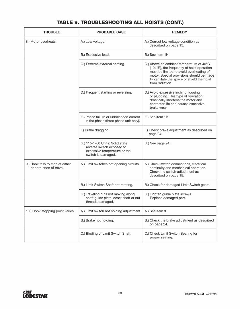
30 31192063792 Rev AA April 2019
TROUBLE PROBABLE CASE REMEDY
8.) Motor overheats. A.) Low voltage. A.) Correct low voltage condition as described on page 15.
B.) Excessive load. B.) See item 1H.
C.) Extreme external heating. C.) Above an ambient temperature of 40°C. (104°F.), the frequency of hoist operation must be limited to avoid overheating of motor. Special provisions should be made to ventilate the space or shield the hoist from radiation.
D.) Frequent starting or reversing. D.) Avoid excessive inching, jogging or plugging. This type of operation drastically shortens the motor and contactor life and causes excessive brake wear.
E.) Phase failure or unbalanced current in the phase (three phase unit only).
E.) See item 1B.
F.) Brake dragging. F.) Check brake adjustment as described on page 24.
G.) 115-1-60 Units: Solid state reverse switch exposed to excessive temperature or the switch is damaged.
G.) See page 24.
9.) Hook fails to stop at either or both ends of travel.
A.) Limit switches not opening circuits. A.) Check switch connections, electrical continuity and mechanical operation. Check the switch adjustment as described on page 15.
B.) Limit Switch Shaft not rotating. B.) Check for damaged Limit Switch gears.
C.) Traveling nuts not moving along shaft guide plate loose; shaft or nut threads damaged.
C.) Tighten guide plate screws. Replace damaged part.
10.) Hook stopping point varies. A.) Limit switch not holding adjustment. A.) See item 9.
B.) Brake not holding. B.) Check the brake adjustment as described on page 24.
C.) Binding of Limit Switch Shaft. C.) Check Limit Switch Bearing for proper seating.
TABLE 9. TROUBLESHOOTING ALL HOISTS (CONT.)
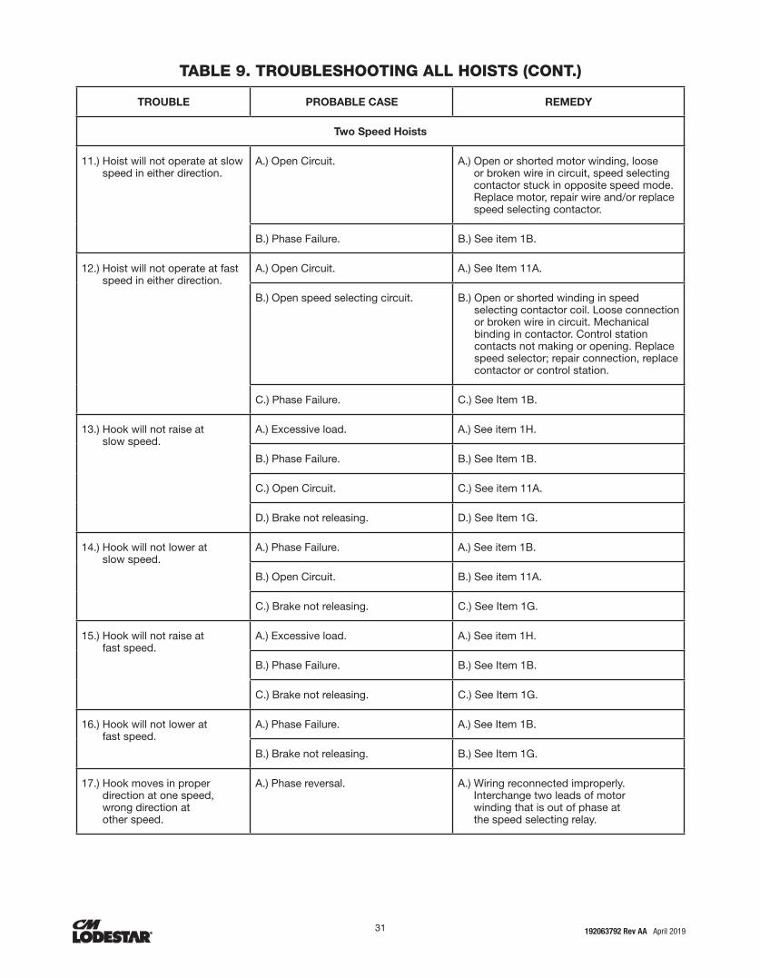
30 31 192063792 Rev AA April 2019
TROUBLE PROBABLE CASE REMEDY
Two Speed Hoists
11.) Hoist will not operate at slow speed in either direction.
A.) Open Circuit. A.) Open or shorted motor winding, loose or broken wire in circuit, speed selecting contactor stuck in opposite speed mode. Replace motor, repair wire and/or replace speed selecting contactor.
B.) Phase Failure. B.) See item 1B.
12.) Hoist will not operate at fast speed in either direction.
A.) Open Circuit. A.) See Item 11A.
B.) Open speed selecting circuit. B.) Open or shorted winding in speed selecting contactor coil. Loose connection or broken wire in circuit. Mechanical binding in contactor. Control station contacts not making or opening. Replace speed selector; repair connection, replace contactor or control station.
C.) Phase Failure. C.) See Item 1B.
13.) Hook will not raise at slow speed.
A.) Excessive load. A.) See item 1H.
B.) Phase Failure. B.) See Item 1B.
C.) Open Circuit. C.) See item 11A.
D.) Brake not releasing. D.) See Item 1G.
14.) Hook will not lower at slow speed.
A.) Phase Failure. A.) See item 1B.
B.) Open Circuit. B.) See item 11A.
C.) Brake not releasing. C.) See Item 1G.
15.) Hook will not raise at fast speed.
A.) Excessive load. A.) See item 1H.
B.) Phase Failure. B.) See Item 1B.
C.) Brake not releasing. C.) See Item 1G.
16.) Hook will not lower at fast speed.
A.) Phase Failure. A.) See Item 1B.
B.) Brake not releasing. B.) See Item 1G.
17.) Hook moves in proper direction at one speed, wrong direction at other speed.
A.) Phase reversal. A.) Wiring reconnected improperly. Interchange two leads of motor winding that is out of phase at the speed selecting relay.
TABLE 9. TROUBLESHOOTING ALL HOISTS (CONT.)
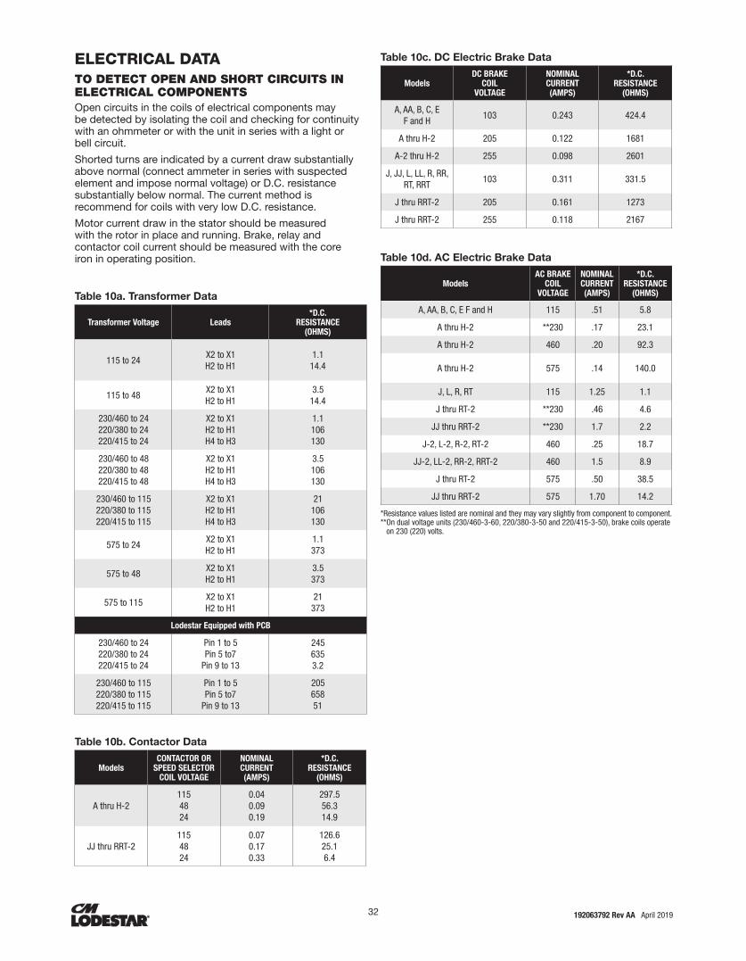
32 33192063792 Rev AA April 2019
ELECTRICAL DATATO DETECT OPEN AND SHORT CIRCUITS IN ELECTRICAL COMPONENTSOpen circuits in the coils of electrical components may be detected by isolating the coil and checking for continuity with an ohmmeter or with the unit in series with a light or bell circuit.
Shorted turns are indicated by a current draw substantially above normal (connect ammeter in series with suspected element and impose normal voltage) or D.C. resistance substantially below normal. The current method is recommend for coils with very low D.C. resistance.
Motor current draw in the stator should be measured with the rotor in place and running. Brake, relay and contactor coil current should be measured with the core iron in operating position.
Table 10a. Transformer Data
Transformer Voltage Leads*D.C.
RESISTANCE (OHMS)
115 to 24 X2 to X1 H2 to H1
1.1 14.4
115 to 48 X2 to X1 H2 to H1
3.5 14.4
230/460 to 24 220/380 to 24 220/415 to 24
X2 to X1 H2 to H1 H4 to H3
1.1 106 130
230/460 to 48 220/380 to 48 220/415 to 48
X2 to X1 H2 to H1 H4 to H3
3.5 106 130
230/460 to 115 220/380 to 115 220/415 to 115
X2 to X1 H2 to H1 H4 to H3
21 106 130
575 to 24 X2 to X1 H2 to H1
1.1 373
575 to 48 X2 to X1 H2 to H1
3.5 373
575 to 115 X2 to X1 H2 to H1
21 373
Lodestar Equipped with PCB
230/460 to 24 220/380 to 24 220/415 to 24
Pin 1 to 5 Pin 5 to7
Pin 9 to 13
245 635 3.2
230/460 to 115 220/380 to 115 220/415 to 115
Pin 1 to 5 Pin 5 to7
Pin 9 to 13
205 658 51
Table 10b. Contactor Data
ModelsCONTACTOR OR
SPEED SELECTORCOIL VOLTAGE
NOMINALCURRENT(AMPS)
*D.C.RESISTANCE
(OHMS)
A thru H-2115 48 24
0.04 0.09 0.19
297.5 56.3 14.9
JJ thru RRT-2115 48 24
0.07 0.17 0.33
126.6 25.1 6.4
Table 10c. DC Electric Brake Data
ModelsDC BRAKE
COILVOLTAGE
NOMINALCURRENT(AMPS)
*D.C.RESISTANCE
(OHMS)
A, AA, B, C, EF and H
103 0.243 424.4
A thru H-2 205 0.122 1681
A-2 thru H-2 255 0.098 2601
J, JJ, L, LL, R, RR, RT, RRT
103 0.311 331.5
J thru RRT-2 205 0.161 1273
J thru RRT-2 255 0.118 2167
Table 10d. AC Electric Brake Data
ModelsAC BRAKE
COILVOLTAGE
NOMINALCURRENT(AMPS)
*D.C.RESISTANCE
(OHMS)
A, AA, B, C, E F and H 115 .51 5.8
A thru H-2 **230 .17 23.1
A thru H-2 460 .20 92.3
A thru H-2 575 .14 140.0
J, L, R, RT 115 1.25 1.1
J thru RT-2 **230 .46 4.6
JJ thru RRT-2 **230 1.7 2.2
J-2, L-2, R-2, RT-2 460 .25 18.7
JJ-2, LL-2, RR-2, RRT-2 460 1.5 8.9
J thru RT-2 575 .50 38.5
JJ thru RRT-2 575 1.70 14.2
*Resistance values listed are nominal and they may vary slightly from component to component. ** On dual voltage units (230/460-3-60, 220/380-3-50 and 220/415-3-50), brake coils operate
on 230 (220) volts.

32 33 192063792 Rev AA April 2019
Models Volts-Phase Hertz H.P. (kW)
Full Load Current (Amps)
Leads*D.C.
Resistance (Ohms)
A,B,E 110-1-50 1/4(.19) 3.21 - 2 3 - 4 5 - 8
7.2 7.2 5.8
A,B,E 115-1-60 1/4 (.19) 4.61 - 2 3 - 4 5 - 8
4.3 4.3 4.9
A,B,E 220-1-50 1/4 (.19) 1.61 - 2 3 - 4 5 - 8
7.2 7.2 5.8
A,B,E 230-1-60 1/4 (.19) 2.31 - 2 3 - 4 5 - 8
4.3 4.3 4.9
AA,C,F,H 110-1-50 1/2 (.37) 6.41 - 2 3 - 4 5 - 8
2.7 2.7 3.5
AA,C,F,H 115-1-60 1/2 (.37) 7.21 - 2 3 - 4 5 - 8
1.9 1.9 3.6
A,B,E 220-1-50 1/2 (.37) 3.21 - 2 3 - 4 5 - 8
2.7 2.7 3.5
A,B,E 230-1-60 1/2 (.37) 3.61 - 2 3 - 4 5 - 8
1.9 1.9 3.6
A,B,E
230/460-3-60
1/4 (.19)
1.4/0.7
3 - 6 2 - 5 1 - 4 8 - 9 8 - 7 9 - 7
14.8 14.8 14.8 29.5 29.5 29.5
220/380-3-50 1.4/0.7
220/415-3-50 1.4/0.7
575-3-60 0.5 1 - 2 2 - 3 1 - 3
550-3-50 0.6
AA,C,F,H
230/460-3-60
1/2 (.37)
1.8/0.9 3 - 6 2 - 5 1 - 4 8 - 9 8 - 7 9 - 7
7.8 7.8 7.8
15.6 15.6 15.6
220/380-3-50 2.1/1.0
220/415-3-50 2.1/1.0
575-3-60 0.8 1 - 2 2 - 3 1 - 3
48.3550-3-50 0.9
A-2, B-2, E-2
230-3-60
.08/.25 (.06/.19)
1.6/1.6 12 - 3 11 - 3 11 - 12 1 - 2 1 - 3 2 - 3
17.5 17.5 17.5 42.5 42.5 42.5
220-3-50 1.9/2.1
A-2, AA-2, B-2, C-2, E-2, F-2,
H-2
230-3-60
.15/.5 (.12/.37)
1.8/2.0 12 - 3 11 - 3 11 - 12 1 - 2 1 - 3 2 - 3
13.5 13.5 13.5 25.0 25.0 25.0
220-3-50 2.1/2.4
460-3-60 1.0/1.0 12 - 3 11 - 3 11 - 12 1 - 2 1 - 3 2 - 3
63.0 63.0 63.0
104.0 104.0 104.0
380-3-50 1.2/1.2
415-3-50 1.2/1.2
575-3-60 .8/.8512 - 3 11 - 3 11 - 12 1 - 2 1 - 3 2 - 3
99.1 99.1 99.1
550-3-50 .8/.85156.0 156.0 156.0
J,L,R,RT110-1-50
1 (.75)11.6 1 - 2
3 - 4 5 - 8
1.1 1.1 1.3
115-1-60 9.8
J,L,R,RT220-1-50
1 (.75)5.8 1 - 2
3 - 4 5 - 8
1.1 1.11.3
230-1-60 4.9
Models Volts-Phase Hertz H.P. (kW)
Full Load Current (Amps)
Leads*D.C.
Resistance (Ohms)
J,L,R,RT 230/460-3-60
1 (.75)
3.0/1.5 3 - 6 2 - 5 1 - 4 8 - 9 8 - 7 9 - 7
4.7 4.7 4.7 9.4 9.4 9.4
J,L,R,RT 220/380-3-50 3.6/1.8
J,L,R,RT 220/415-3-50 3.6/1.8
J,L,R,RT 575-3-60 1.5 1 - 2 2 - 3 1 - 3
29.6J,L,R,RT 550-3-50 1.8
JJ, LL, RR, RRS, RRT
230/460-3-60
2 (1.5)
5.8/2.9 3 - 6 2 - 5 1 - 4 8 - 9 8 - 7 9 - 7
2.2 2.2 2.2 9.4 9.4 9.4
220/380-3-50 6.4/3.3
220/415-3-50 6.4/3.3
575-3-60 3.2 1 - 2 2 - 3 1 - 3
14.8550-3-50 3.5
J-2,L-2,R-2, RT-2
230-3-60
.33/1 (.25/.75)
3.4/5.0 12 - 3 11 - 3
11 - 12 1 - 2 1 - 3 2 - 3
7.7 7.7 7.7 19.4 19.4 19.4
220-3-50 3.2/4.7
460-3-60 1.5/2.4 12 - 3 11 - 3
11 - 12 1 - 2 1 - 3 2 - 3
29.9 29.4 29.0 80.2 80.1 82.2
380-3-50 1.6/2.4
415-3-50 1.6/2.4
575-3-60 1.1/1.9 12 - 3 11 - 3
11 - 12 1 - 2 1 - 3 2 - 3
42.9 40.1 53.2 125.7 125.8 125.2
550-3-50 1.3/2.1
JJ-2, LL-2, RR-2, RRT-2
230-3-60
.67/2 (.50/1.5)
5.8/8.8 12 - 3 11 - 3
11 - 12 1 - 2 1 - 3 2 - 3
3.2 3.1 3.3 14.1 14.1 14.0
220-3-50 6.6/9.5
460-3-60 3.3/5.1 12 - 3 11 - 3
11 - 12 1 - 2 1 - 3 2 - 3
11.4 11.3 11.3 55.2 55.4 55.3
380-3-50 3.0/5.0
415-3-60 3.0/5.0
575-3-60 2.3/3.5
12 - 3 11 - 3
11 - 12 1 - 2 1 - 3 2 - 3
17.0 17.1 17.2 84.1 84.0 83.6
Table 10e. Motor Data

34 35192063792 Rev AA April 2019
Table 11a. Torque Specification: All Models
Fastener Fastener Description Tool Required*Recommended Seating Torque
ft-lbf N-m
Brake End Cover 1/4"-20 Socket Head Cap Screw 3/16" Hex Driver 4.2-5.0 5.7-6.8
Motor End Cover 1/4"-20 Socket Head Cap Screw 3/16" Hex Driver 4.2-5.0 5.7-6.8
Reversing Contactor Connecting Screws - 1Ø
Terminal Clamp ScrewPhilips No. 2 or
3/16" slotted head screwdriver0.6-1.0 0.8-1.3
Reversing Contactor Connecting Screws - 3Ø
Terminal Clamp ScrewPhilips No. 2 or
3/16" slotted head screwdriver0.6-1.0 0.8-1.3
Limit Switch Guide Screws#10-24 Button Head Socket
Cap Screw5/32" Hex Driver 1.7-2.1 2.3-2.8
#6-32 Contactor Plate Screw#6-32 Button Head Socket
Cap Screw5/64" Hex Driver 0.7-0.8 0.9-1.1
#8-32 Contactor Plate Screw#8-32 Button Head Socket
Cap Screw3/32" Hex Driver 1.1-1.4 1.5-1.9
#10-24 Contactor Plate Screw#10-24 Button Head Socket
Cap Screw5/32" Hex Driver 1.7-2.1 2.3-2.8
1/4-20 Screw for Miscellaneous Applications
1/4"-20 Button Head Socket Cap Screw
5/32" Hex Driver 4.2-5.0 5.7-6.8
Cord Grips 3/4" NPT Cord Grip 1-1/16" Hex Socket or Wrench 5.0-5.8 6.8-7.9
Cord Grip Dome Nut1-1/16" Dome Nut
for Cord Grip2X 1-1/16" Wrench,
hold cord grip while tightening nut
3.3-4.5 4.5-6.1
Or until cord does not slip
Table 11b. Torque Specification: Models A-H
Fastener Screw Size Tool Required*Recommended Seating Torque
ft-lbf N-m
Motor Housing/ Gear Housing/ Back Frame Screws
1/4"-20 Socket Head Cap Screw 3/16" Hex Driver 7.9-8.3 10.7-11.3
Lift-Wheel Nut 1"-12 Hex Nut 1-1/2" Socket 55.0-60.0 74.6-81.3
Brake Attaching Screws 1/4"-20 Button Head Socket Cap Screw 5/32" Hex Driver 4.2-5.0 5.6-6.8
Brake Field Mounting Screws M5 Socket Head Cap Screw 4mm Hex Driver 4.0-4.7 5.4-6.4
Contactor Plate/PCB Mounting Nuts
1/4"-20 Hex Nut 7/16" Socket 2.0-2.5 2.7-3.4
Suspension Adapter Screws 3/8-16 12 Point Cap Screw3/8"
12 Point Socket35.0-45.0 47.5-61.0
Lower Hook Block Screws (Double Reeved Units)
1/4"-20 Socket Head Cap Screw 3/16" Hex Driver 5.0-5.8 6.8-7.9
Loose End Screw 1/4"-20 Socket Head Cap Screw 3/16" Hex Driver 4.2-5.0 5.6-6.8
Chain Stop Screw 1/4"-20 Socket Head Cap Screw 3/16" Hex Driver 5.0-5.8 6.8-7.9
TORQUE SPECIFICATIONS
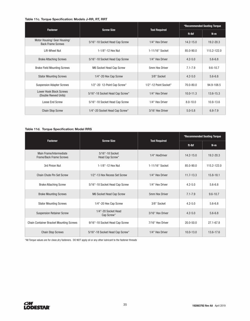
34 35 192063792 Rev AA April 2019
Table 11c. Torque Specification: Models J-RR, RT, RRT
Fastener Screw Size Tool Required*Recommended Seating Torque
ft-lbf N-m
Motor Housing/ Gear Housing/ Back Frame Screws
5/16"-18 Socket Head Cap Screw 1/4" Hex Driver 14.2-15.0 19.2-20.3
Lift-Wheel Nut 1-1/8"-12 Hex Nut 1-11/16" Socket 85.0-90.0 115.2-122.0
Brake Attaching Screws 5/16"-18 Socket Head Cap Screw 1/4" Hex Driver 4.2-5.0 5.6-6.8
Brake Field Mounting Screws M6 Socket Head Cap Screw 5mm Hex Driver 7.1-7.9 9.6-10.7
Stator Mounting Screws 1/4"-20 Hex Cap Screw 3/8" Socket 4.2-5.0 5.6-6.8
Suspension Adapter Screws 1/2"-20 12-Point Cap Screw" 1/2"-12 Point Socket" 70.0-80.0 94.9-108.5
Lower Hook Block Screws (Double Reeved Units)
5/16"-18 Socket Head Cap Screw" 1/4" Hex Driver 10.0-11.3 13.6-15.3
Loose End Screw 5/16"-18 Socket Head Cap Screw 1/4" Hex Driver 8.0-10.0 10.8-13.6
Chain Stop Screw 1/4"-20 Socket Head Cap Screw" 3/16' Hex Driver 5.0-5.8 6.8-7.9
Table 11d. Torque Specification: Model RRS
Fastener Screw Size Tool Required
*Recommended Seating Torque
ft-lbf N-m
Main Frame/Intermediate Frame/Back Frame Screws
5/16"-18 Socket Head Cap Screw"
1/4" HexDriver 14.2-15.0 19.2-20.3
3rd Pinion Nut 1-1/8"-12 Hex Nut 1-11/16" Socket 85.0-90.0 115.2-122.0
Chain Chute Pin Set Screw 1/2"-13 Hex Recess Set Screw 1/4" Hex Driver 11.7-13.3 15.8-18.1
Brake Attaching Screw 5/16"-18 Socket Head Cap Screw 1/4" Hex Driver 4.2-5.0 5.6-6.8
Brake Mounting Screws M6 Socket Head Cap Screw 5mm Hex Driver 7.1-7.9 9.6-10.7
Stator Mounting Screws 1/4"-20 Hex Cap Screw 3/8" Socket 4.2-5.0 5.6-6.8
Suspension Retainer Screw1/4"-20 Socket Head
Cap Screw"3/16" Hex Driver 4.2-5.0 5.6-6.8
Chain Container Bracket Mounting Screws 9/16"-18 Socket Head Cap Screw 7/16" Hex Driver 20.0-50.0 27.1-67.8
Chain Stop Screws 5/16"-18 Socket Head Cap Screw" 1/4" Hex Driver 10.0-13.0 13.6-17.6
*All Torque values are for clean,dry fasteners. DO NOT apply oil or any other lubricant to the fastener threads

© 2019 Columbus McKinnon Corporation. All Rights Reserved.
INDEMNIFICATION AND SAFE OPERATION
Buyer shall comply with and require its employees to comply with directions set forth in instructions and manuals furnished by Seller and shall useand require its employees to follow such instructions and manuals andto use reasonable care in the use and maintenance of the Goods and any Replacement Parts. Buyer shall not remove or permit anyone to remove any warning or instruction signs on the Goods or Replacement Parts. In the event of personal injury or damage to property or business arising from the use of the Goods or Replacement Parts, Buyer shall within 48 hours thereafter give Seller written notice of such injury or damage. Buyer shall cooperate with Seller in investigating any such injury or damage and in the defense of any claims arising therefrom.
If Buyer fails to comply with this section or if any injury or damage is caused, in whole or in part, by Buyer’s failure to comply with applicable federal or state laws, rules or regulations safety requirements, Buyer shall indemnify and hold Seller harmless against any claims, loss or expense for injury or damage arising from the use of the Goods and/or Replacement Parts.
CMCO Warranty (HOISTS)
A. Columbus McKinnon Corporation (“Seller”) warrants to the original end user (“Buyer”) that: (a) for a period of one (1) year from the date of Seller’s delivery of the goods (collectively, the “Goods”) to the carrier, the electrical components of the Goods will be free from defects in workmanship and materials; and (b) for the life of the Goods, the mechanical components of the Goods will be free from defects in workmanship and materials. In addition, Seller warrants to Buyer that, for a period of one (1) year from the date of their delivery by Seller to the carrier, any aftermarket or replacement parts, accessories or components purchased by Buyer with respect to any Goods (collectively, “Replacement Parts”) will be free from defects in workmanship and materials.
B. IN THE EVENT OF ANY BREACH OF ANY SUCH WARRANTY, SELLER’S SOLE OBLIGATION SHALL BE EXCLUSIVELY LIMITED TO, AT THE OPTION OF SELLER, REPAIR OR REPLACEMENT, F.O.B. SELLER’S POINT OF SHIPMENT, OF ANY GOODS OR REPLACEMENT PARTS THAT SELLER DETERMINES TO HAVE BEEN DEFECTIVE OR, IF SELLER DETERMINES THAT SUCH REPAIR OR REPLACEMENT IS NOT FEASIBLE, TO A REFUND OF THE PURCHASE PRICE UPON RETURN OF THE GOODS OR REPLACEMENT PARTS TO SELLER. NO CLAIM AGAINST SELLER FOR ANY BREACH OF (i) SUCH WARRANTY WITH RESPECT TO THE ELECTRICAL COMPONENTS OF ANY GOOD, OR ANY REPLACEMENT PART, SHALL BE VALID OR ENFORCEABLE UNLESS BUYER’S WRITTEN NOTICE THEREOF IS RECEIVED BY SELLER WITHIN ONE (1) YEAR FROM THE DATE OF SELLER’S DELIVERY TO THE CARRIER AND (ii) SUCH WARRANTY WITH RESPECT TO THE MECHANICAL COMPONENTS OF ANY GOOD SHALL BE VALID OR ENFORCEABLE UNLESS BUYER’S WRITTEN NOTICE THEREOF IS RECEIVED BY SELLER WITHIN ONE (1) YEAR FROM THE DATE THE DATE ANY ALLEGED CLAIM ACCRUES. EXCEPT FOR THE WARRANTIES SET FORTH ABOVE, SELLER MAKES NO OTHER WARRANTIES WITH RESPECT TO THE GOODS OR ANY REPLACEMENT PART, WHETHER EXPRESSED OR IMPLIED, INCLUDING ANY WARRANTIES OF MERCHANTABILITY, FITNESS FOR A PARTICULAR PURPOSE, QUALITY AND/OR THOSE ARISING BY STATUTE OR OTHERWISE BY LAW OR FROM ANY COURSE OF DEALING OR USE OF TRADE, ALL OF WHICH ARE HEREBY EXPRESSLY DISCLAIMED.
C. IN NO EVENT SHALL SELLER BE LIABLE TO BUYER OR ANY THIRD
PARTY WITH RESPECT TO ANY GOOD OR REPLACEMENT PART, WHETHER IN CONTRACT, TORT OR OTHER THEORY OF LAW, FOR LOSS OF PROFITS OR LOSS OF USE, OR FOR ANY INCIDENTAL, CONSEQUENTIAL, SPECIAL, DIRECT OR INDIRECT DAMAGES, HOWSOEVER CAUSED. SELLER’S MAXIMUM LIABILITY TO BUYER WITH RESPECT TO THE GOODS OR ANY REPLACEMENT PART SHALL IN NO EVENT EXCEED THE PRICE PAID BY BUYER FOR THE GOODS OR REPLACEMENT PART THAT ARE THE SUBJECT OF THE APPLICABLE CLAIM.
D. Seller shall not be liable for any damage, injury or loss arising out of the use of the Goods or any Replacement Part if, prior to such damage, injury or loss, such Goods or Replacement Parts are: (1) damaged or misused following Seller’s delivery to the carrier; (2) not maintained, inspected, or used in compliance with applicable law and Seller’s written instructions and recommendations; or (3) installed, repaired, altered or modified (a) with any part or accessory other than those supplied by Seller or (b) without compliance with such laws, instructions or recommendations
E. This warranty is limited and provided only to the original end user. Each Good and Replacement Part must be registered within sixty (60) days of receipt of each product to establish eligibility. Please register at www.cmworks.com/hoist-warranty-registration or submit registration card via US mail.
F. Any action against Seller for breach of warranty, negligence or otherwise in connection with the electrical components of any Good must be commenced by Buyer within one (1) year after: (a) the date any alleged claim accrues; or (b) the date of delivery of the Goods to Buyer, whichever is earlier. Any action against Seller for breach of warranty, negligence or otherwise in connection with the mechanical components of any Good must be commenced by Buyer within one (1) year after the date any alleged claim accrues. Any action against Seller for breach of warranty, negligence or otherwise in connection with any Replacement Part must be commenced by Buyer within one (1) year after: (y) the date any alleged claim accrues; or (z) the date of delivery of the Replacement Part to Buyer, whichever is earlier.
G. This warranty is contingent upon Buyer’s proper maintenance and care of the Goods and/or Replacement Parts, and does not extend to normal wear and tear. Seller reserves the right, at its option, to void this warranty in the event of Buyer’s use with the Goods and/or Replacement Parts of parts or accessories other than those supplied by Seller.
Alterations or modifications of equipment and use of non-Seller replacement parts can lead to dangerous operation and injury.
TO AVOID INJURY:
• Do not alter or modify equipment. • Do use only replacement parts manufactured by seller.
WARRANTYLIMITATION OF WARRANTIES, REMEDIES AND DAMAGES
Partners In Motion C ontro l
USA: Ph: (800) 888.0985 • (716) 689.5400 • Fax: (716) 689.5644 • www.cmworks.com
CANADA: Ph: (877) 264.6478 • Fax: (877) 264.6477 • www.cmworks.com
GERMANY: Ph: +49 7940 128-0• Fax +49 7940 55665• www.stahlcranes.com