Installation, Operation, and Maintenance · Responsible Refrigerant Practices! Trane believes that...
44
SAFETY WARNING Only qualified personnel should install and service the equipment. The installation, starting up, and servicing of heating, ventilating, and air-conditioning equipment can be hazardous and requires specific knowledge and training. Improperly installed, adjusted or altered equipment by an unqualified person could result in death or serious injury. When working on the equipment, observe all precautions in the literature and on the tags, stickers, and labels that are attached to the equipment. Axiom™ High Efficiency Console Water-Source Heat Pump ½ to 1½ Tons—60 Hz December 2011 WSHP-SVX11A-EN Models “E” and later design 60 Hz GECE - 006, 009, 012, 015, 018 50 Hz GECE - 006, 009, 012, 015 Installation, Operation, and Maintenance
Transcript of Installation, Operation, and Maintenance · Responsible Refrigerant Practices! Trane believes that...

SAFETY WARNINGOnly qualified personnel should install and service the equipment. The installation, starting up, and servicing of heating, ventilating, and air-conditioning equipment can be hazardous and requires specific knowledge and training. Improperly installed, adjusted or altered equipment by an unqualified person could result in death or serious injury. When working on the equipment, observe all precautions in the literature and on the tags, stickers, and labels that are attached to the equipment.
Axiom™ High Efficiency Console
Water-Source Heat Pump
½ to 1½ Tons—60 Hz
December 2011 WSHP-SVX11A-EN
Models “E” and later design
60 Hz GECE - 006, 009, 012, 015, 01850 Hz GECE - 006, 009, 012, 015
Installation, Operation,
and Maintenance
© 2011 Trane All rights reserved WSHP-SVX11A-EN
Warnings, Cautions and Notices
Warnings, Cautions and Notices. Note that warnings, cautions and notices appear at appropriate intervals throughout this manual. Warnings are provide to alert installing contractors to potential hazards that could result in death or personal injury. Cautions are designed to alert personnel to hazardous situations that could result in personal injury, while notices indicate a situation that could result in equipment or property-damage-only accidents.
Your personal safety and the proper operation of this machine depend upon the strict observance of these precautions.
Read this manual thoroughly before operating or servicing this unit.
Important
Environmental Concerns!
Scientific research has shown that certain man-made chemicals can affect the earth’s naturally occurring stratospheric ozone layer when released to the atmosphere. In particular, several of the identified chemicals that may affect the ozone layer are refrigerants that contain Chlorine, Fluorine and Carbon (CFCs) and those containing Hydrogen, Chlorine, Fluorine and Carbon (HCFCs). Not all refrigerants containing these compounds have the same potential impact to the environment. Trane advocates the responsible handling of all refrigerants-including industry replacements for CFCs such as HCFCs and HFCs.
Responsible Refrigerant Practices!
Trane believes that responsible refrigerant practices are important to the environment, our customers, and the air conditioning industry. All technicians who handle refrigerants must be certified. The Federal Clean Air Act (Section 608) sets forth the requirements for handling, reclaiming, recovering and recycling of certain refrigerants and the equipment that is used in these service procedures. In addition, some states or municipalities may have additional requirements that must also be adhered to for responsible management of refrigerants. Know the applicable laws and follow them.
ATTENTION: Warnings, Cautions and Notices appear at appropriate sections throughout this literature. Read these carefully:
WARNING Indicates a potentially hazardous situation which, if not avoided, could result in death or serious injury.
CAUTIONsIndicates a potentially hazardous situation which, if not avoided, could result in minor or moderate injury. It could also be used to alert against unsafe practices.
NOTICE: Indicates a situation that could result in equipment or property-damage only accidents
WARNING
Proper Field Wiring and Grounding Required!
All field wiring MUST be performed by qualified personnel. Improperly installed and grounded field wiring poses FIRE and ELECTROCUTION hazards. To avoid these hazards, you MUST follow requirements for field wiring installation and grounding as described in NEC and your local/state electrical codes. Failure to follow code could result in death or serious injury.

WSHP-SVX11A-EN 3
Trademarks
Trademarks
Trane and the Trane logo are trademarks of Trane in the United States and other countries. All trademarks referenced in this document are the trademarks of their respective owners.
WARNING
Personal Protective Equipment (PPE) Required!
Installing/servicing this unit could result in exposure to electrical, mechanical and chemical hazards.
• Before installing/servicing this unit, technicians MUST put on all Personal Protective
Equipment (PPE) recommended for the work being undertaken. ALWAYS refer to appropriate
MSDS sheets and OSHA guidelines for proper PPE.
• When working with or around hazardous chemicals, ALWAYS refer to the appropriate MSDS
sheets and OSHA guidelines for information on allowable personal exposure levels, proper
respiratory protection and handling recommendations.
• If there is a risk of arc or flash, technicians MUST put on all Personal Protective Equipment
(PPE) in accordance with NFPA 70E or other country-specific requirements for arc flash
protection, PRIOR to servicing the unit.
Failure to follow recommendations could result in death or serious injury.

4 WSHP-SVX11A-EN
Table of Contents
General Information . . . . . . . . . . . . . . . . . . . . . . . . . . . . . . . . . . . . . . . . . . . . . . . . . . . . 5Jobsite Inspection . . . . . . . . . . . . . . . . . . . . . . . . . . . . . . . . . . . . . . . . . . . . . 5Jobsite Storage . . . . . . . . . . . . . . . . . . . . . . . . . . . . . . . . . . . . . . . . . . . . . . . 5
Model Number Description . . . . . . . . . . . . . . . . . . . . . . . . . . . . . . . . . . . . . . . . . . . . . . 6
Unit Dimensions and Weights . . . . . . . . . . . . . . . . . . . . . . . . . . . . . . . . . . . . . . . . . . . 7Unit Clearance . . . . . . . . . . . . . . . . . . . . . . . . . . . . . . . . . . . . . . . . . . . . . . . . 7
Installation . . . . . . . . . . . . . . . . . . . . . . . . . . . . . . . . . . . . . . . . . . . . . . . . . . . . . . . . . . . . 21
Performance Data . . . . . . . . . . . . . . . . . . . . . . . . . . . . . . . . . . . . . . . . . . . . . . . . . . . . . 24Operating Pressures . . . . . . . . . . . . . . . . . . . . . . . . . . . . . . . . . . . . . . . . . . 24Water Pressure Drop . . . . . . . . . . . . . . . . . . . . . . . . . . . . . . . . . . . . . . . . . . 27Water Volume . . . . . . . . . . . . . . . . . . . . . . . . . . . . . . . . . . . . . . . . . . . . . . . 27
Electrical Data . . . . . . . . . . . . . . . . . . . . . . . . . . . . . . . . . . . . . . . . . . . . . . . . . . . . . . . . . 28
Pre-Start . . . . . . . . . . . . . . . . . . . . . . . . . . . . . . . . . . . . . . . . . . . . . . . . . . . . . . . . . . . . . . 30Pre-Startup Checklist . . . . . . . . . . . . . . . . . . . . . . . . . . . . . . . . . . . . . . . . . . 30
Start-Up . . . . . . . . . . . . . . . . . . . . . . . . . . . . . . . . . . . . . . . . . . . . . . . . . . . . . . . . . . . . . . 31Initial Unit Start-up . . . . . . . . . . . . . . . . . . . . . . . . . . . . . . . . . . . . . . . . . . . 31
Maintenance . . . . . . . . . . . . . . . . . . . . . . . . . . . . . . . . . . . . . . . . . . . . . . . . . . . . . . . . . . 33Preventive Maintenance . . . . . . . . . . . . . . . . . . . . . . . . . . . . . . . . . . . . . . . 33Filter Replacement (standard height configuration) . . . . . . . . . . . . . . . . . 33Filter Replacement (low height configuration) . . . . . . . . . . . . . . . . . . . . . 34
Troubleshooting . . . . . . . . . . . . . . . . . . . . . . . . . . . . . . . . . . . . . . . . . . . . . . . . . . . . . . . 35Deluxe Controls . . . . . . . . . . . . . . . . . . . . . . . . . . . . . . . . . . . . . . . . . . . . . . 36
Unit Wiring . . . . . . . . . . . . . . . . . . . . . . . . . . . . . . . . . . . . . . . . . . . . . . . . . . . . . . . . . . . 37
Warranty . . . . . . . . . . . . . . . . . . . . . . . . . . . . . . . . . . . . . . . . . . . . . . . . . . . . . . . . . . . . . 43Standard Warranty . . . . . . . . . . . . . . . . . . . . . . . . . . . . . . . . . . . . . . . . . . . 43Extended Warranty . . . . . . . . . . . . . . . . . . . . . . . . . . . . . . . . . . . . . . . . . . . 43

WSHP-SVX11A-EN 5
General Information
Jobsite Inspection
Each unit has been inspected, tested and operated at the factory by production and quality associates prior to being crated for safe transit. However, rough handling or accidents can occur resulting in damaged equipment being delivered. Always perform the following checks before accepting a unit:
1. Do not sign the bill of lading accepting the unit(s) until inspection has been completed. Check for damage promptly after the unit(s) are unloaded. Once the bill of lading is signed at the jobsite, the unit(s) are now the property of the SOLD TO party and future freight claims MAY NOT be accepted by the freight company.
2. Check the unit model numbers on the bill of lading against those ordered and received to assure equipment is AS ORDERED.
3. Check to assure that the refrigerant charge has been retained during shipment by use of gauges. Schrader taps are located and labeled internal to the cabinet. (See Figure 1).
Important: After assuring that charge has been retained re-install schrader caps to assure that refrigerant leakage does not occur and unit panel using all factory provided screws.
Jobsite Storage
This unit is intended for indoor use only. To protect the unit from damage due to the elements, and to prevent possible IAQ contaminant sources from growing, the unit should be stored indoors. If indoor storage is not possible, the following provisions for outdoor storage must be met.
1. Place the unit(s) on a dry surface or raise above the ground to assure adequate air circulation beneath the unit. This is to assure that no portion of the unit contacts standing water at any time.
2. Cover the unit(s) with a water proof tarp to protect them from the elements.
3. Make provisions for continuous venting of the covered units to prevent moisture from standing on the unit(s) surfaces. Wet interior unit insulation can become an amplification site for microbial growth which has been determined to be a cause of odors and serious health related indoor air quality problems.
4. Store units in the normal UP orientation. Storing units in this manner maintains oil in the compressor.
5. Units may be stacked two high.
Important: Equipment is shipped FOB (Free on Board) at the manufacturer. Therefore, freight claims for damages against the carrier must be initiated by the receiver.
Figure 1. Schrader location
6 WSHP-SVX11A-EN
Digit 1-3: Unit ConfigurationGEC = High Efficiency Console
Digit 4: Development SequenceE
Digits 5-7: Nominal Capacity006 = ½ Ton009 = ¾ Ton012 = 1 Ton015 = 1¼ Ton018 = 1½ Ton
Digit 8: Voltage (Volts/Hz/Phase)0 = 115/60/1 1 = 208/60/1 2 = 230/60/1 6 = 220-240/50/17 = 265/60/1
Digit 9: Heat Exchanger1 = Copper-Water Coil2 = Cupro-Nickel Water Coil
Digit 10: Current Design SequenceA
Digit 11: Refrigeration Circuit0 = Heating and Cooling Circuit2 = Heating and Cooling Circuit with
Hot Gas Reheat
Digit 12: Blower Configuration1 = Standard Blower Motor
Digit 13: Freeze Protection0 = None or StandardA = 20° FreezestatB = 35° Freezestat
Digit 14: Open Digit 0 = Open DigitS = Design Special
Digit 15: Supply-Air Arrangement0 = Standard Supply-Air
Arrangement
Digit 16: Return-Air Arrangement0 = Standard Return-Air
Arrangement
Digit 17: Control Types0 = Basic 24V ControlsD = Deluxe 24V ControlsC = Tracer ZN510 ControlsB = Tracer ZN524 ControlsE = Deluxe 24V Control with Low
Temp Unoccupied Sensor &Programmable Thermostat
Digit 18: Tstat/Sensor Location0 = Wall Mounted Location1 = Unit Mounted Location with
Standard Entry2 = Unit Mounted Location with
Key lock Entry
Digit 19: Fault Sensors0 = No Fault Sensor1 = Condensate Overflow Sensor2 = Filter Maintenance Timer3 = Condensate Overflow and Filter
Maintenance Timer4 = Fan Status Sensor6 = Condensate Overflow and Fan
StatusH = Fan Status and Filter Maintenance
TimerJ = Fan Status, Filter Maintenance
Timer and Condensate Overflow Sensor
Digit 20: Temperature Sensor0 = No Additional Temperature
Sensor1 = Entering Water Sensor
Digit 21: Open Digit0 = Open Digit
Digit 22: Electric Heat0 = No Electric Heat2 = Boilerless Control Electric Heat
(minimum)3 = Boilerless Control Electric Heat
(maximum)
Digit 23: Unit Mounted Disconnect0 = No Unit Mounted DisconnectA = Power Cord/Receptacle Box B = Power Cord/Receptacle Box
with Circuit BreakerC = On/Off Toggle Switch
Digit 24: Filter Type0 = No Filter; Chassis Only1 = 1" Throwaway FilterA = 1" Pleated Filter
Digit 25: Acoustic Arrangement0 = Enhanced Sound Attenuation
Digit 26: Factory Configuration0 = Standard Factory Configuration
(Chassis, Cabinet and Subbase)1 = Chassis ONLY2 = Low Height Factory
Configuration (Chassis, Cabinet and Subbase)
3 = Extended Length Factory Configuration (Chassis, Cabinet and Subbase)
Digit 27: Paint Color0 = No Paint Selection Available 1 = Deluxe Beige2 = Cameo White3 = Soft Dove
Digit 28: Outside Air0 = No Outside Air Option1 = Outside Air Opening2 = Motorized Outside Air
(2-position)
Digit 29: Piping ArrangementL = Left Hand Piping ArrangementR = Right Hand Piping Arrangement
Digit 30-36: Does Not Apply to GEC0000000 = Digits 30-36 are not
applicable to the GEC product
Model Number Description

WSHP-SVX11A-EN 7
Unit Dimensions and Weights
Unit Clearance
Access to the unit for servicing purposes should be provided at installation. All configurations require clearance from other mechanical and electrical equipment on three service sides (shown below). This enables panel removal from the unit for service/maintenance ability.
Figure 2. Unit clearances
Table 1. Unit weights
Unit Size Without Pallet With Pallet
60 Hz 50 HzUnit Weight
(lbs)Chassis Weight
(lbs)Unit Weight
(lbs)Chassis Weight
(lbs)
006 — 188 140 218 170
009 006 189 141 219 171
012 009 210 162 240 192
015 012 204 156 234 186
018 015 212 164 242 194

8 WSHP-SVX11A-EN
Unit Dimensions and Weights
Figure 3. GECE 006-018 (60 Hz); GECE 006-015 (50 Hz)—cabinet (RH) piping connection
48"
12"
CONTROL
ACCESS
PANEL
2 1/2"
6" LONG, 5/8" I.D.
PLASTIC HOSE
PROVIDED FOR
CONDENSATE
CONNECTION
3 3/8"
2 3/4"
5 5/8"32 5/8" 6"
3 3/4"
4"7/8"
1 3
/4"
3/4"
1 3/4"
4 3/8"
7/8"
25"
23 3
/4"
22 3
/8"
10 3
/8"
21 7
/8"
10"
11 1/4"
ELECT. FIELD
HOOK-UP
(4) 1/4" WALL SLEEVE
MOUNTING HOLES
RETURN-AIR OPENING
O/A OPENING
TOP VIEW
FRONT VIEW RIGHT SIDE VIEW
BACK VIEW
WATER-OUT
5/8" ODS
WATER-IN
5/8" ODS
PLASTIC DRAIN
5/8" I.D.
FIELD ADJUSTABLE
BI-DIRECTIONAL GRILLES
9 3/4"
3/4"
4 3/4"
3/4"
7 1/4"
15 3/4"
47 1/4"
PIPE & ELEC.
FIELD HOOK-UP
15" 9 1/4"
4 1
/2"
3 5/8" 5/8"

WSHP-SVX11A-EN 9
Unit Dimensions and Weights
Figure 4. GECE 006-018 (60 Hz); GECE 006-015 (50 Hz)—cabinet (LH) piping connection
3 1/4"
3/4"9 5/8"
3/4"
47 1/4"
15"
7/8"
4"
5/8"
6 1/2"
1 3/4"
3/4"13"
PIPE & ELEC.FIELD HOOK-UP
7 1/4"
15 3/4"
(4) .250 WALL SLEEVE MOUNTING HOLES
FILTER ACCESS
32 5/8"
3 3/4"
FOR CONDENSATE
2 1/2"
CONNECTION
2 3/4"
3 3/8"
PLASTIC HOSE6" LONG
6"
1 3/4"
UNIT CONTROLLER
4 3/8"
21 7/8"
11 1/4"
DRAIN CONN..625 I.D.
10"
7 7/8"
23 3/4"
22 3/8"
25"
.625 ODS
WATER IN CONN..625 ODS
WATER OUT
7/8"
17 1/4"
6 1/2"
RECEPTACLE BOX
48"
12"
SUPPLY AIR GRILLE
SIDE VIEW
BACK VIEW
FRONT VIEW
BACK UNITPIPE & ELEC.
FIELD HOOK-UP
TOP VIEW

10 WSHP-SVX11A-EN
Unit Dimensions and Weights
Figure 5. GECE 006-018 (60 Hz); GECE 006-015 (50 Hz)—subbase (RH)
4 3/4"
48"
9 1/4"
32 5/8"
6"
15"
9 5
/8"
3/4"
11 1
/4"
3 3
/4"
3/4
"
TOP VIEW
ISO VIEW
WSHP-SVX11A-EN 11
Unit Dimensions and Weights
Figure 6. GECE 006-018 (60 Hz); GECE 006-015 (50 Hz)—subbase (LH)
4 3/4"
48"
13"
32 5/8"
6"
15"
9 5
/8"
3/4"
11 1
/4"
3 3
/4"
3/4
"
TOP VIEW
ISO VIEW

12 WSHP-SVX11A-EN
Unit Dimensions and Weights
Figure 7. GECE 006-018 (60 Hz); GECE 006-015 (50 Hz)—cabinet (RH) piping extended length
19"8 7/8"
3/4"
3/4"
O/A OPENING15" 3/4"
1 3/4"
9 1/4"
(4).25 WALL SLEEVE MOUNTING HOLES
19"
7/8"
4 1/2"
3 5/8"
10 1/2"
7/8"
4 3/8"
6 1/4"
21 7/8" 23 3/4"
22 3/8"
11 1/4"
25"
PLASTIC DRAIN CONN..625 I.D.
WATER IN CONN..625 O.D.S.
WATER OUT CONN.625 O.D.S.
17 1/4"
6 1/2"
RECEPTACLE BOX
UNIT CONTROLLER
32 5/8"
3 3/4"
FILTER ACCESS
2 1/2"
6" LONG PLASTIC HOSEFOR CONDENSATE CONN.
6"
1 3/4"
18 1/4"
17 3/4"
63"
12"
SUPPLY AIR GRILLE
PIPE & ELEC. FIELD HOOK-UP.
SIDE VIEWFRONT VIEW
BACK VIEW
TOP VIEW
BACK OF UNIT

WSHP-SVX11A-EN 13
Unit Dimensions and Weights
Figure 8. GECE 006-018 (60 Hz); GECE 006-015 (50 Hz)—cabinet (LH) piping extended length
ELECTRIC & PIPEFIELD HOOK UP
62 1/4"
15"
1 3/4"
3/4"
7/8"19"
3 5/8"
4 1/2"
28"
O/A OPENING
7 1/4"
15 3/4"
(4) .25 WALL SLEEVEMOUNTING HOLES
4 3/8"
21 7/8"
11 1/4"
PLASTIC DRAIN CONN..625 I.D.
10"
7 7/8"
23 3/4"
22 3/8"
25"
WATER OUT.625 ODS
WATER IN CONN.625 ODS
7/8"
RECEPTACLE BOX
6" LONG PLASTIC HOSE FOR CONDENSATE CONN.
32 5/8"
3 3/4"2 1/2"
18 1/2"
17 3/4"
FILTER ACCESS
6"
1 3/4"
UNIT CONTROLLER
63"
SUPPLY AIR GRILLE
12"
19"
3/4"
8 7/8"3/4"
SIDE VIEW
BACK VIEW
FRONT VIEW
BACK OF UNIT
PIPE & ELEC.FIELD HOOK-UP
TOP VIEW

14 WSHP-SVX11A-EN
Unit Dimensions and Weights
Figure 9. GECE 006-018 (60 Hz); GECE 006-015 (50 Hz)—subbase (RH) extended length
19 3/4"
63"
9 1/4"
32 5/8"
6"
15"
9 5
/8"
3/4"
11 1
/4"
3 3
/4"
3/4
"
TOP VIEW
ISO VIEW
WSHP-SVX11A-EN 15
Unit Dimensions and Weights
Figure 10. GECE 006-018 (60 Hz); GECE 006-015 (50 Hz)—subbase (LH) extended length
19 3/4"
63"
28"
32 5/8"
6"
15"
9 5
/8"
3/4"
11 1
/4"
3 3
/4"
3/4
"
TOP VIEW
ISO VIEW

16 WSHP-SVX11A-EN
Unit Dimensions and Weights
Figure 11. GECE 006-018 (60 Hz); GECE 006-015 (50 Hz)—cabinet (RH) low height unit
3/4"
3/4"
4"9 5/8"
10 1/2"
7/8"
4 3/8"
3 3/4"
19 3/8"21 1/4"
19 7/8"
11 1/4"
22 1/2"
.625 I.D.DRAIN CONN. WATER IN
.625 ODS
WATER OUT.625 ODS
14 3/4"
6 1/2"
RECEPTACLE BOX
PIPE & ELECTRICALFIELD HOOK-UP
47 1/4"
4 3/4"
15 3/4"
(4) .25 WALL SLEEVEMOUNTING HOLES4"
7/8"
4 1/2"
3 5/8"
34 3/4"1 3/4"
RETURN AIR OPENING
1 1/4"
6" LONG,PLASTIC HOSE PROVIDED FORCONDENSATECONNECTION
1 1/2"
7 3/4"
3 3/8"
2 3/4"UNIT CONTROLLER
48"
12 3/8"
FIELD ADJUSTABLEBI-DIRECTIONAL GRILLES
SIDE VIEW
BACK VIEW
FRONT VIEW
TOP VIEW
PIPE & ELECTRICALFIELD HOOK-UP
BACK OF UNIT

WSHP-SVX11A-EN 17
Unit Dimensions and Weights
Figure 12. GECE 006-018 (60 Hz); GECE 006-015 (50 Hz)—cabinet (LH) low height unit
4"
3/4"3/4"
8 7/8"
47 1/4"
7/8"
4"
3 5/8"
4 1/2"
PIPE & ELECTRICFIELD HOOK-UP
4 3/4"
15 3/4"
(4) .250 WALL SLEEVEMOUNTING HOLES
48"
FIELD ADJUSTABLEBI-DIRECTIONAL GRILLES
12"
34 3/4"1 3/4" 1 1/4"
6" LONG PLASTIC HOSE
PROVIDED FORCONDENSATECONNECTION.
1 1/2"
7 3/4"
2 3/4"
3 3/8"CONTROLACCESSPANEL
4 3/8"
19 3/8"
11 1/4"
DRAIN CONN..625 I.D.
10"
7 7/8"
21 1/4"
19 7/8"
22 1/2"
.625 ODSWATER OUT
.625 ODSWATER IN
7/8"
RECEPTACLE BOX
SIDE VIEW
BACK VIEW
FRONT VIEW
TOP VIEW
PIPE & ELEC.FIELD HOOK-UP
BACK OF UNIT

18 WSHP-SVX11A-EN
Unit Dimensions and Weights
Figure 13. GECE 006-018 (60 Hz); GECE 006-015 (50 Hz)—chassis (RH)
3"
1 7/8"
3/4"
4 1/2"
13 1/4"
2 1/4"
14 1/2"
3 3/4"
2"
5/8"
17 1/4"
CUT OUT FORLOW VOLTAGE
TERMINAL STRIP
6 1/2"
10 1/2"
AIR SIDESERVICE PANEL
20 3/8"
REFRIGERATIONSERVICE PANEL
.625ODSWATER IN
2 1/8"
1 1/2"
6" LONG, 625 I.D.PLASTIC HOSE PROVIDEFOR CONDENSATE CONNECTION.
WATER OUT.625 ODS
42 1/4"
COTROL BOXSERVICE PANEL
2 3/8"
11 1/2"6 3/8"
4 1/4"
2x4 HIGH VOLTAGE BOX
RIGHT SIDE VIEWFRONT VIEW
TOP VIEW
WSHP-SVX11A-EN 19
Unit Dimensions and Weights
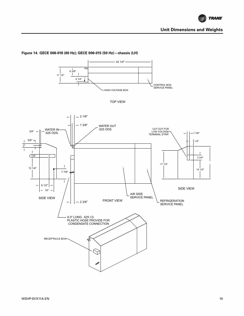
Figure 14. GECE 006-018 (60 Hz); GECE 006-015 (50 Hz)—chassis (LH)
3"
1 7/8"
17 1/4"
14 1/2"
3 3/4"
CUT OUT FORLOW VOLTAGE
TERMINAL STRIP.
7 7/8"13 1/4"
2 1/4"
3/4"
5/8"
2"
10"
6 1/2"
WATER OUT.625 ODS.
2 3/8"
1 3/8"
2 1/8"
CONDENSATE CONNECTIONPLASTIC HOSE PROVIDE FOR6.0" LONG. .625 I.D.
.625 ODS.WATER IN
AIR SIDESERVICE PANEL
REFRIGERATIONSERVICE PANEL
HIGH VOLTAGE BOX
42 1/4"
11 1/2"4 1/4"
6 3/8"
CONTROL BOXSERVICE PANEL
RECEPTACLE BOX
FRONT VIEW
TOP VIEW
SIDE VIEW
SIDE VIEW

20 WSHP-SVX11A-EN
Unit Dimensions and Weights
Table 2. Models GECE 006–012
Model GEC 006 009 012
Unit Size Length (in.) 48 or 63 48 or 63 48 or 63
Height (in.) 25 or 22½ 25 or 22½ 25 or 22½
Width (in.) 12 or 12 3/8 12 or 12 3/8 12 or 12 3/8
Compressor Type Rotary Rotary Rotary
R-410A Refrigerant (lbs) Heating and Cooling 1.47 1.50 1.57
Hot Gas Reheat 1.56 1.59 1.66
Approximate Weight without Pallet (lbs) Unit 188 189 210
Chassis Only 140 141 162
Approximate Weight with Pallet (lbs) Unit 218 219 240
Chassis Only 170 171 192
Filter Size (standard height-25 in.) 1 x 10 x 32 3/8 1 x 10 x 32 3/8 1 x 10 x 32 3/8
Filter Size (low height-22½ in.) 1 x 7¾ x 30 5/8 1 x 7¾ x 30 5/8 1 x 7¾ x 30 5/8
Blower Wheel Size (in) (1) 5¼ x 8 1/8 (2) 5¼ x 8 1/8 (2) 5¼ x 8 1/8
Table 3. Models GECE 015–018
Model GEC 015 018
Unit Size Length (in) 48 or 63 48 or 63
Height (in) 25 or 22½ 25 or 22½
Width (in) 12 or 12 3/8 12 or 12 3/8
Compressor Type Rotary Rotary
R-410A Refrigerant (lbs) Heating and Cooling 1.69 1.88
Hot Gas Reheat 1.81 2.06
Approximate Weight without Pallet (lbs) Unit 204 212
Chassis Only 156 164
Approximate Weight with Pallet (lbs) Unit 234 242
Chassis Only 186 194
Filter Size (standard height-25 in.) 1 x 10 x 32 3/8 1 x 10 x 32 3/8
Filter Size (low height-22½ in.) 1 x 7¾ x 30 5/8 1 x 7¾ x 30 5/8
Blower Wheel Size (in.) (2) 5¼ x 8 1/8 (2) 5¼ x 8 1/8

WSHP-SVX11A-EN 21
Installation
1. Uncrate Unit. Remove packaging and inspect the unit. Carefully remove the stretch wrap and cardboard pieces. The installation literature and may be found on the back of the unit in a clear, plastic bag. Unit has been tied to skid by (2) shipping brackets.
2. Inspect Unit. Remove refrigeration panel and inspect the unit. Be certain the refrigerant tubing has clearance from adjacent parts. Verify that the electrical connections are tight and in-place.
3. Mounting to Wall. With the chassis still on the subbase, align the unit to the wall. If unit contains an outside air option, align the wall cut-out to the subbase outside-air cut-out. Level the unit per plan requirements. Mark the four mounting locations for wall sleeve mounting to the wall. The dimensions should fall in line with Step 5.
4. Remove Chassis. Remove the chassis from the subbase via 6 screws. The chassis is attached to both the subbase and the wall sleeve (see diagram above). To assure proper alignment, re-install screws 2 and 3 in the final installation of the unit (Step 11).
5. Wall Flange. After removing chassis from the subbase, install the wall flange assembly to the desired wall with the use of four #10-field provided screws. The wall flange assembly includes four,¼ in. diameter clearance holes.
6. Mounting of Receptacle Box (receptacle box - OPTION). Mounting of the receptacle box should be made prior to piping and electrical hook-up. This factory disconnect option is designed to fit inside the end pocket. Mount the receptacle box 2 in. above the top of the subbase with four, #8-field supplied screws.
22 WSHP-SVX11A-EN
Installation
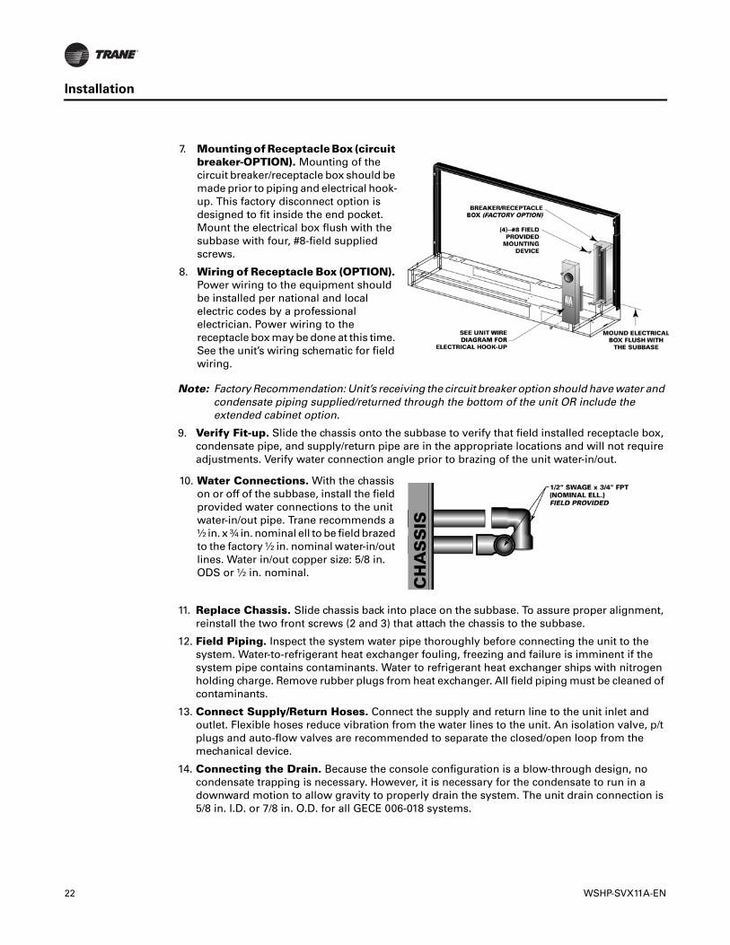
Note: Factory Recommendation: Unit’s receiving the circuit breaker option should have water and condensate piping supplied/returned through the bottom of the unit OR include the extended cabinet option.
9. Verify Fit-up. Slide the chassis onto the subbase to verify that field installed receptacle box, condensate pipe, and supply/return pipe are in the appropriate locations and will not require adjustments. Verify water connection angle prior to brazing of the unit water-in/out.
11. Replace Chassis. Slide chassis back into place on the subbase. To assure proper alignment, reinstall the two front screws (2 and 3) that attach the chassis to the subbase.
12. Field Piping. Inspect the system water pipe thoroughly before connecting the unit to the system. Water-to-refrigerant heat exchanger fouling, freezing and failure is imminent if the system pipe contains contaminants. Water to refrigerant heat exchanger ships with nitrogen holding charge. Remove rubber plugs from heat exchanger. All field piping must be cleaned of contaminants.
13. Connect Supply/Return Hoses. Connect the supply and return line to the unit inlet and outlet. Flexible hoses reduce vibration from the water lines to the unit. An isolation valve, p/t plugs and auto-flow valves are recommended to separate the closed/open loop from the mechanical device.
14. Connecting the Drain. Because the console configuration is a blow-through design, no condensate trapping is necessary. However, it is necessary for the condensate to run in a downward motion to allow gravity to properly drain the system. The unit drain connection is 5/8 in. I.D. or 7/8 in. O.D. for all GECE 006-018 systems.
7. Mounting of Receptacle Box (circuit breaker-OPTION). Mounting of the circuit breaker/receptacle box should be made prior to piping and electrical hook-up. This factory disconnect option is designed to fit inside the end pocket. Mount the electrical box flush with the subbase with four, #8-field supplied screws.
8. Wiring of Receptacle Box (OPTION). Power wiring to the equipment should be installed per national and local electric codes by a professional electrician. Power wiring to the receptacle box may be done at this time. See the unit’s wiring schematic for field wiring.
10. Water Connections. With the chassis on or off of the subbase, install the field provided water connections to the unit water-in/out pipe. Trane recommends a ½ in. x ¾ in. nominal ell to be field brazed to the factory ½ in. nominal water-in/out lines. Water in/out copper size: 5/8 in. ODS or ½ in. nominal.

WSHP-SVX11A-EN 23
Installation
15. Wiring Connections. Power wiring to the equipment should be installed per national and local electric codes by a professional electrician. Refer to Step 6, Step 7, and Step 8 for units that include the factory supplied receptacle box.
For units containing a field provided disconnect, or, are hard wired to the unit, Trane provides pig tail leads inside a 2 x 4 handy-box in either the right or left side end pocket. See unit wiring schematic for details.
For units containing a wall mounted thermostat, a low voltage (18-pole) terminal strip is provided for field installation of the thermostat. See Step 18 for unit mounted controls.
16. Wall Mounted Control. The thermostat hook-up to the unit is made at the unit mounted 24V (18-pole) low voltage terminal strip. This strip is mounted on the exterior of the control box on the right side of the unit. For units that contain left hand piping, a low voltage crossover to the 18-pole terminal strip may be necessary. For this configuration, run the low voltage wires behind the chassis to the right side of the console unit for termination to the terminal strip.
WARNING
Grounding required!
Follow proper local and state electrical code on requirements for grounding. Failure to follow code could result in death or serious injury.
17. Thermostat Location. Location of the thermostat or zone sensor is an important element of effective room control. Areas where the thermostat/zone sensor should not be mounted include: behind doors or corners; near hot or cold air ducts; near radiant heat (heat emitted from appliances or sun); near concealed pipes or chimneys; on outside walls or other non conditioned surfaces; in air-flows from adjacent zones or other units.
18. Unit Mounted Controls (Option). For units with unit mounted controls, all low voltage connections are factory made. The fan will run continuous with unit mounted controls.
19. Receptacle Plug (Option). For units with the factory provided receptacle box options, the receptacle plug may now be connected to the electrical outlet.
5 Fe
et
YESNO
NO
NOO

24 WSHP-SVX11A-EN
Performance Data
Operating Pressures
GENERAL: There are many variables (airflow, air temperatures) in an air conditioning system that affect operating refrigerant pressures and temperatures. The charts below shows approximate conditions and is based on air flow at the rated SCFM, entering air at 80.6°F(DB), 66.2°F(WB) in cooling, 68°F(DB) in heating. (+)Heating data with 35°F EWT is based on the use of an anti-freeze solution having a freezing point 20°F lower than the minimum expected entering temperature.
Table 4. Operating pressures in cooling/heating for unit sizes 006–018
Operating Data
Model GECE
Entering Water
Temp, °F
Water Flow GPM
Cooling Heating
Suction Pressure,
PSIG
Discharge Pressure,
PSIG
Water Temp
Rise °F
Air Temp Drop °F
DB
Suction Pressure
PSIG
Discharge Pressure,
PSIG
Water Temp
Drop °F
Air Temp Rise °F
DB
006 (60 Hz) 35° 1.4 — — — — 91-105 255-325 10-13 21-26
006 (60 Hz) 35° 1.8 — — — — 92-106 255-325 8-10 21-27
006 (60 Hz) 45° 1.4 142-164 188-239 12-16 23-29 107-123 267-339 11-14 24-30
006 (60 Hz) 45° 1.8 142-163 179-228 10-12 23-29 110-126 269-342 9-12 24-31
006 (60 Hz) 55° 1.4 144-165 217-276 12-15 23-29 124-143 279-355 12-16 27-34
006 (60 Hz) 55° 1.8 143-165 207-263 9-12 23-29 128-147 282-359 10-13 27-35
006 (60 Hz) 68° 1.4 146-168 259-329 12-15 22-28 149-172 297-378 14-18 31-39
006 (60 Hz) 68° 1.8 145-167 247-314 9-12 22-28 154-177 300-382 11-14 32-40
006 (60 Hz) 75° 1.4 147-169 280-357 11-15 21-27 164-189 307-391 15-19 33-42
006 (60 Hz) 75° 1.8 147-169 271-345 9-12 21-27 170-196 310-395 12-15 34-43
006 (60 Hz) 86° 1.4 147-170 331-422 12-15 20-26 190-219 323-411 16-21 36-46
006 (60 Hz) 86° 1.8 147-169 321-409 9-12 20-26 197-227 327-417 13-17 37-47
006 (60 Hz) 95° 1.4 148-170 392-498 12-15 19-24 — — — —
006 (60 Hz) 95° 1.8 148-170 379-483 9-12 19-25 — — — —
009 (60 Hz) 006 (50 Hz)
35° 1.7 — — — — 93-107 258-328 10-12 21-26
009 (60 Hz) 006 (50 Hz)
35° 2.1 — — — — 93-107 258-329 8-10 21-27
009 (60 Hz) 006 (50 Hz)
45° 1.7 149-171 189-241 13-16 23-29 108-125 271-344 11-14 24-30
009 (60 Hz) 006 (50 Hz)
45° 2.1 146-168 183-233 10-13 23-29 111-128 273-347 9-11 24-31
009 (60 Hz) 006 (50 Hz)
55° 1.7 144-166 216-275 12-15 23-29 126-145 284-362 12-15 27-34
009 (60 Hz) 006 (50 Hz)
55° 2.1 145-167 210-267 10-12 23-29 129-149 287-365 10-13 27-35
009 (60 Hz) 006 (50 Hz)
68° 1.7 146-169 254-323 11-14 22-28 152-175 303-386 14-17 31-39
009 (60 Hz) 006 (50 Hz)
68° 2.1 146-168 247-315 9-12 22-28 157-180 306-390 11-14 32-40
009 (60 Hz) 006 (50 Hz)
75° 1.7 146-168 280-356 11-14 21-27 167-193 313-399 14-18 33-42
009 (60 Hz) 006 (50 Hz)
75° 2.1 146-168 270-344 9-11 21-27 173-199 317-403 12-15 34-43
009 (60 Hz) 006 (50 Hz)
86° 1.7 146-168 333-424 11-14 20-26 194-224 330-420 16-20 36-46
continued on next page
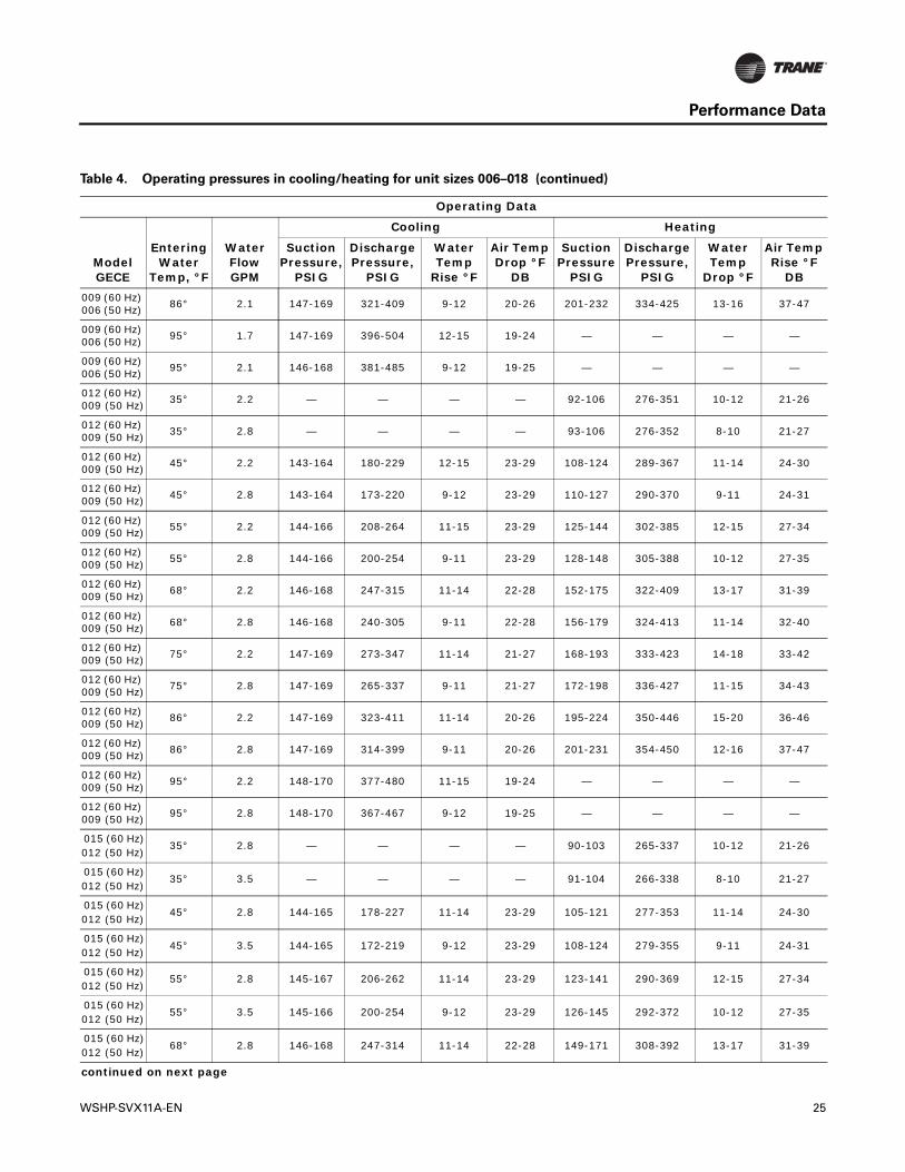
WSHP-SVX11A-EN 25
Performance Data
009 (60 Hz) 006 (50 Hz)
86° 2.1 147-169 321-409 9-12 20-26 201-232 334-425 13-16 37-47
009 (60 Hz) 006 (50 Hz)
95° 1.7 147-169 396-504 12-15 19-24 — — — —
009 (60 Hz) 006 (50 Hz)
95° 2.1 146-168 381-485 9-12 19-25 — — — —
012 (60 Hz) 009 (50 Hz)
35° 2.2 — — — — 92-106 276-351 10-12 21-26
012 (60 Hz) 009 (50 Hz) 35° 2.8 — — — — 93-106 276-352 8-10 21-27
012 (60 Hz) 009 (50 Hz)
45° 2.2 143-164 180-229 12-15 23-29 108-124 289-367 11-14 24-30
012 (60 Hz) 009 (50 Hz)
45° 2.8 143-164 173-220 9-12 23-29 110-127 290-370 9-11 24-31
012 (60 Hz) 009 (50 Hz) 55° 2.2 144-166 208-264 11-15 23-29 125-144 302-385 12-15 27-34
012 (60 Hz) 009 (50 Hz)
55° 2.8 144-166 200-254 9-11 23-29 128-148 305-388 10-12 27-35
012 (60 Hz) 009 (50 Hz)
68° 2.2 146-168 247-315 11-14 22-28 152-175 322-409 13-17 31-39
012 (60 Hz) 009 (50 Hz) 68° 2.8 146-168 240-305 9-11 22-28 156-179 324-413 11-14 32-40
012 (60 Hz) 009 (50 Hz)
75° 2.2 147-169 273-347 11-14 21-27 168-193 333-423 14-18 33-42
012 (60 Hz) 009 (50 Hz)
75° 2.8 147-169 265-337 9-11 21-27 172-198 336-427 11-15 34-43
012 (60 Hz) 009 (50 Hz) 86° 2.2 147-169 323-411 11-14 20-26 195-224 350-446 15-20 36-46
012 (60 Hz) 009 (50 Hz)
86° 2.8 147-169 314-399 9-11 20-26 201-231 354-450 12-16 37-47
012 (60 Hz) 009 (50 Hz)
95° 2.2 148-170 377-480 11-15 19-24 — — — —
012 (60 Hz) 009 (50 Hz)
95° 2.8 148-170 367-467 9-12 19-25 — — — —
015 (60 Hz)012 (50 Hz)
35° 2.8 — — — — 90-103 265-337 10-12 21-26
015 (60 Hz)012 (50 Hz)
35° 3.5 — — — — 91-104 266-338 8-10 21-27
015 (60 Hz)012 (50 Hz)
45° 2.8 144-165 178-227 11-14 23-29 105-121 277-353 11-14 24-30
015 (60 Hz)012 (50 Hz)
45° 3.5 144-165 172-219 9-12 23-29 108-124 279-355 9-11 24-31
015 (60 Hz)012 (50 Hz)
55° 2.8 145-167 206-262 11-14 23-29 123-141 290-369 12-15 27-34
015 (60 Hz)012 (50 Hz)
55° 3.5 145-166 200-254 9-12 23-29 126-145 292-372 10-12 27-35
015 (60 Hz)012 (50 Hz)
68° 2.8 146-168 247-314 11-14 22-28 149-171 308-392 13-17 31-39
continued on next page
Table 4. Operating pressures in cooling/heating for unit sizes 006–018 (continued)
Operating Data
Model GECE
Entering Water
Temp, °F
Water Flow GPM
Cooling Heating
Suction Pressure,
PSIG
Discharge Pressure,
PSIG
Water Temp
Rise °F
Air Temp Drop °F
DB
Suction Pressure
PSIG
Discharge Pressure,
PSIG
Water Temp
Drop °F
Air Temp Rise °F
DB
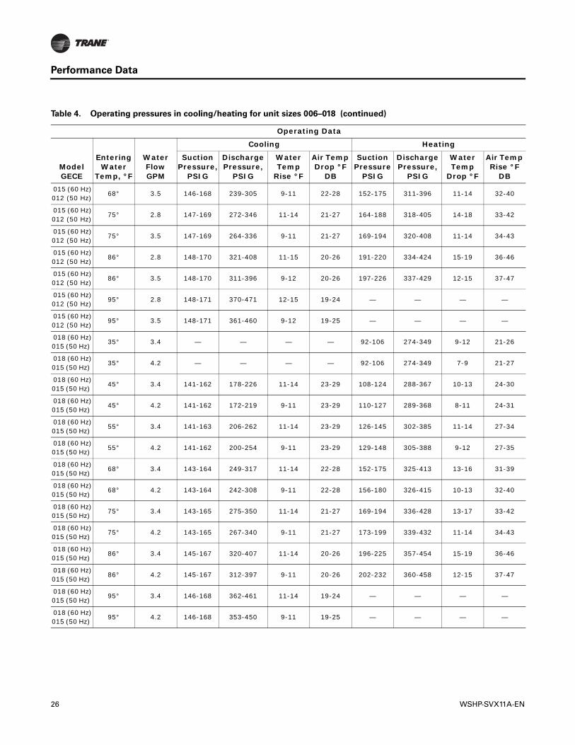
26 WSHP-SVX11A-EN
Performance Data
015 (60 Hz)012 (50 Hz)
68° 3.5 146-168 239-305 9-11 22-28 152-175 311-396 11-14 32-40
015 (60 Hz)012 (50 Hz)
75° 2.8 147-169 272-346 11-14 21-27 164-188 318-405 14-18 33-42
015 (60 Hz)012 (50 Hz)
75° 3.5 147-169 264-336 9-11 21-27 169-194 320-408 11-14 34-43
015 (60 Hz)012 (50 Hz)
86° 2.8 148-170 321-408 11-15 20-26 191-220 334-424 15-19 36-46
015 (60 Hz)012 (50 Hz)
86° 3.5 148-170 311-396 9-12 20-26 197-226 337-429 12-15 37-47
015 (60 Hz)012 (50 Hz)
95° 2.8 148-171 370-471 12-15 19-24 — — — —
015 (60 Hz)012 (50 Hz)
95° 3.5 148-171 361-460 9-12 19-25 — — — —
018 (60 Hz)015 (50 Hz)
35° 3.4 — — — — 92-106 274-349 9-12 21-26
018 (60 Hz)015 (50 Hz)
35° 4.2 — — — — 92-106 274-349 7-9 21-27
018 (60 Hz)015 (50 Hz)
45° 3.4 141-162 178-226 11-14 23-29 108-124 288-367 10-13 24-30
018 (60 Hz)015 (50 Hz)
45° 4.2 141-162 172-219 9-11 23-29 110-127 289-368 8-11 24-31
018 (60 Hz)015 (50 Hz)
55° 3.4 141-163 206-262 11-14 23-29 126-145 302-385 11-14 27-34
018 (60 Hz)015 (50 Hz)
55° 4.2 141-162 200-254 9-11 23-29 129-148 305-388 9-12 27-35
018 (60 Hz)015 (50 Hz)
68° 3.4 143-164 249-317 11-14 22-28 152-175 325-413 13-16 31-39
018 (60 Hz)015 (50 Hz)
68° 4.2 143-164 242-308 9-11 22-28 156-180 326-415 10-13 32-40
018 (60 Hz)015 (50 Hz)
75° 3.4 143-165 275-350 11-14 21-27 169-194 336-428 13-17 33-42
018 (60 Hz)015 (50 Hz)
75° 4.2 143-165 267-340 9-11 21-27 173-199 339-432 11-14 34-43
018 (60 Hz)015 (50 Hz)
86° 3.4 145-167 320-407 11-14 20-26 196-225 357-454 15-19 36-46
018 (60 Hz)015 (50 Hz)
86° 4.2 145-167 312-397 9-11 20-26 202-232 360-458 12-15 37-47
018 (60 Hz)015 (50 Hz)
95° 3.4 146-168 362-461 11-14 19-24 — — — —
018 (60 Hz)015 (50 Hz)
95° 4.2 146-168 353-450 9-11 19-25 — — — —
Table 4. Operating pressures in cooling/heating for unit sizes 006–018 (continued)
Operating Data
Model GECE
Entering Water
Temp, °F
Water Flow GPM
Cooling Heating
Suction Pressure,
PSIG
Discharge Pressure,
PSIG
Water Temp
Rise °F
Air Temp Drop °F
DB
Suction Pressure
PSIG
Discharge Pressure,
PSIG
Water Temp
Drop °F
Air Temp Rise °F
DB

WSHP-SVX11A-EN 27
Performance Data
Water Pressure Drop
Table 5, p. 27 should be used to define feet of head/pressure drop. Please note the feet of pressure (ft/head) provided is at ARI/ISO standard.
Note: To calculate feet of head, when using gauges that read in PSIG, multiply PSI by 2.31.
Water Volume
Table 6 is provided for use in calculating glycol requirements for the unit.
Table 5. Water pressure drops
Cooling WPD in feet of head Heating WPD in feet of head
Unit Size 60
Hz
Unit Size 50
Hz EWT F GPMFt.
Pressure
Unit Size 60
Hz
Unit Size 50
Hz EWT F GPMFt.
Pressure
006 — 86 1.8 3.6 006 — 68 1.8 4.3
009 006 86 2.1 4.3 009 006 68 2.1 5.0
012 009 86 2.8 9.3 012 009 68 2.8 10.7
015 012 86 3.5 13.1 015 012 68 3.5 14.9
018 015 86 4.2 9.1 018 015 68 4.2 10.2
Table 6. Water volume
Unit Size 60 Hz
Unit Size 50 Hz
Water side Volume
Cubic In.
Water side Volume Cubic Ft.
Water Side Volume Gallons
006-009 006 13.6 0.008 0.059
012-15 009-12 23.1 0.013 0.100
018 015 36 0.021 0.156

28 WSHP-SVX11A-EN
Electrical Data
Table 7. GECE electrical data
Model No. Unit Volts
Total Unit FLA
Comp.RLA(ea)
Comp.LRA(ea)
No. ofComp.
CmpMCC
BlowerMotorFLA
BlowerMotor
hP
Fan MotorNum.
Minimum CircuitAmpacit
y
Maximum Overcurrent Protective
Device
Electric Heat
Size kW Amps
006 115/60/1 6.5 5.6 30.0 1 7.5 0.90 1/20 1 7.9 15 None 0 0
006 208/60/1 4.1 3.3 14.0 1 4.2 0.80 1/20 1 4.9 15 None 0 0
006 208/60/1 11.6 3.3 14.0 1 4.2 0.80 1/20 1 14.5 15 Min 2.25 10.82
006 208/60/1 15.2 3.3 14.0 1 4.2 0.80 1/20 1 19.0 20 Max 3 14.42
006 230/60/1 3.9 3.2 15.0 1 4.2 0.70 1/20 1 4.7 15 None 0 0
006 230/60/1 13.2 3.2 15.0 1 4.2 0.70 1/20 1 16.5 20 Min 3 12.5
006 220-240/50/1 3.6 2.9 17.0 1 4.0 0.70 1/20 1 4.3 15 None 0 0
006 220-240/50/1 13.2 2.9 17.0 1 4.0 0.70 1/20 1 16.5 20 Min 3 12.5
006 265/60/1 3.2 2.5 11.0 1 3.5 0.70 1/20 1 3.8 15 None 0 0
006 265/60/1 11.5 2.5 11.0 1 3.5 0.70 1/20 1 14.4 15 Min 3 10.83
009 115/60/1 7.3 6.4 36.0 1 8.6 0.90 1/20 1 8.9 15 None 0 0
009 208/60/1 4.5 3.7 16.0 1 4.8 0.80 1/20 1 5.4 15 None 0 0
009 208/60/1 11.6 3.7 16.0 1 4.8 0.80 1/20 1 14.5 15 Min 2.25 10.82
009 208/60/1 15.2 3.7 16.0 1 4.8 0.80 1/20 1 19.0 20 Max 3 14.42
009 230/60/1 4.2 3.5 17.0 1 4.8 0.70 1/20 1 5.1 15 None 0 0
009 230/60/1 13.2 3.5 17.0 1 4.8 0.70 1/20 1 16.5 20 Min 3 12.5
009 230/60/1 17.4 3.5 17.0 1 4.8 0.70 1/20 1 21.7 25 Max 4 16.67
009 220-240/50/1 6.0 5.3 23.0 1 7.4 0.70 1/12 1 7.3 15 None 0 0
009 220-240/50/1 13.2 5.3 23.0 1 7.4 0.70 1/12 1 16.5 20 Min 3 12.5
009 220-240/50/1 17.4 5.3 23.0 1 7.4 0.70 1/12 1 21.7 25 Max 4 16.67
009 265/60/1 3.5 2.8 13.0 1 3.7 0.70 1/20 1 4.2 15 None 0 0
009 265/60/1 11.5 2.8 13.0 1 3.7 0.70 1/20 1 14.4 15 Min 3 10.83
009 265/60/1 15.1 2.8 13.0 1 3.7 0.70 1/20 1 18.9 20 Max 4 14.44
012 115/60/1 13.3 12.1 58.0 1 16.9 1.20 1/12 1 16.3 20 None 0 0
012 208/60/1 7.2 6.3 30.0 1 8.8 0.90 1/12 1 8.8 15 None 0 0
012 208/60/1 11.7 6.3 30.0 1 8.8 0.90 1/12 1 14.7 15 Min 2.25 10.82
012 208/60/1 15.3 6.3 30.0 1 8.8 0.90 1/12 1 19.2 20 Max 3 14.42
012 230/60/1 7.0 6.3 30.0 1 8.8 0.70 1/12 1 8.6 15 None 0 0
012 230/60/1 13.2 6.3 30.0 1 8.8 0.70 1/12 1 16.5 20 Min 3 12.5
012 230/60/1 17.4 6.3 30.0 1 8.8 0.70 1/12 1 21.7 25 Max 4 16.67
012 220-240/50/1 7.4 6.7 30.0 1 9.4 0.70 1/12 1 9.1 15 None 0 0
012 220-240/50/1 13.2 6.7 30.0 1 9.4 0.70 1/12 1 16.5 20 Min 3 12.5
012 220-240/50/1 17.4 6.7 30.0 1 9.4 0.70 1/12 1 21.7 25 Max 4 16.67
012 265/60/1 5.7 5.0 23.0 1 7.0 0.70 1/12 1 7.0 15 None 0 0
012 265/60/1 11.5 5.0 23.0 1 7.0 0.70 1/12 1 14.4 15 Min 3 10.83
012 265/60/1 15.1 5.0 23.0 1 7.0 0.70 1/12 1 18.9 20 Max 4 14.44
015 115/60/1 16.1 14.9 60.0 1 20.9 1.20 1/12 1 19.8 20 None 0 0
015 208/60/1 8.9 7.9 36.0 1 11.1 1.00 1/12 1 10.9 15 None 0 0
015 208/60/1 11.8 7.9 36.0 1 11.1 1.00 1/12 1 14.8 15 Min 2.25 10.82
015 208/60/1 15.4 7.9 36.0 1 11.1 1.00 1/12 1 19.3 20 Max 3 14.42
continued on next page

WSHP-SVX11A-EN 29
Electrical Data
015 230/60/1 8.8 7.9 36.0 1 11.1 0.90 1/12 1 10.8 15 None 0 0
015 230/60/1 13.4 7.9 36.0 1 11.1 0.90 1/12 1 16.8 20 Min 3 12.5
015 230/60/1 17.6 7.9 36.0 1 11.1 0.90 1/12 1 22.0 25 Max 4 16.67
015 220-240/50/1 8.6 7.9 28.0 1 11.1 0.70 1/12 1 10.6 15 None 0 0
015 220-240/50/1 13.2 7.9 28.0 1 11.1 0.70 1/6 1 16.5 20 Min 3 12.5
015 220-240/50/1 17.4 7.9 28.0 1 11.1 0.70 1/6 1 21.7 25 Max 4 16.67
015 265/60/1 7.1 6.4 30.0 1 9.0 0.70 1/6 1 8.7 15 None 0 0
015 265/60/1 11.5 6.4 30.0 1 9.0 0.70 1/12 1 14.4 15 Min 3 10.83
015 265/60/1 15.1 6.4 30.0 1 9.0 0.70 1/12 1 18.9 20 Max 4 14.44
018 208/60/1 10.0 9.0 30.0 1 12.6 1.00 1/6 1 12.3 15 None 0 0
018 208/60/1 11.8 9.0 30.0 1 12.6 1.00 1/6 1 14.8 15 Min 2.25 10.82
018 208/60/1 15.4 9.0 30.0 1 12.6 1.00 1/6 1 19.3 20 Max 3 14.42
018 230/60/1 9.9 9.0 30.0 1 12.6 0.90 1/6 1 12.2 15 None 0 0
018 230/60/1 13.4 9.0 30.0 1 12.6 0.90 1/6 1 16.8 20 Min 3 12.5
018 230/60/1 17.6 9.0 30.0 1 12.6 0.90 1/6 1 22.0 25 Max 4 16.67
018 265/60/1 8.5 7.8 30.0 1 10.9 0.70 1/6 1 10.5 15 None 0 0
018 265/60/1 11.5 7.8 30.0 1 10.9 0.70 1/6 1 14.4 15 Min 3 10.83
018 265/60/1 15.1 7.8 30.0 1 10.9 0.70 1/6 1 18.9 20 Max 4 14.44
Table 7. GECE electrical data (continued)
Model No. Unit Volts
Total Unit FLA
Comp.RLA(ea)
Comp.LRA(ea)
No. ofComp.
CmpMCC
BlowerMotorFLA
BlowerMotor
hP
Fan MotorNum.
Minimum CircuitAmpacit
y
Maximum Overcurrent Protective
Device
Electric Heat
Size kW Amps

30 WSHP-SVX11A-EN
Pre-Start
Pre-Startup Checklist
Before energizing the unit, the following system devices must be checked:
• Is the high voltage power supply correct and in accordance with the nameplate ratings?
• Is the field wiring and circuit protection the correct size?
• Is the low voltage control circuit wiring correct per the unit wiring diagram?
• Is the piping system clean/complete and correct? (A recommendation of all system flushing of debris from the water-to-refrigerant heat exchanger, along with air purging from the water-to-refrigerant heat exchanger be done in accordance with the Closed-Loop/Ground Source Heat Pump Systems Installation Guide).
• Is vibration isolation provided? (i.e. unit isolation pad, hose kits)
• Is unit serviceable? (Allow a 12" clearance at the unit front for serviceability).
• Are the low/high-side pressure temperature caps secure and in place?
• Are all the unit access panels secure and in place?
• Is the thermostat in the OFF position?
• Is the water flow established and circulating through all the units?
• Is the duct work correctly sized, run, taped, insulated and weather proofed with proper unit arrangement?
• Is the condensate line properly sized, run, and pitched?
• Is the zone sensor (when used) correctly wired and in a good location?
• Does the indoor blower turn freely without rubbing?
• Has all work been done in accordance with applicable local and national codes?
• Has heat transfer fluid been added in the proper mix to prevent freezing in closed system application?
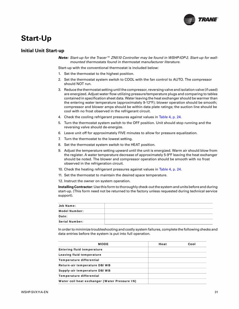
WSHP-SVX11A-EN 31
Start-Up
Initial Unit Start-up
Note: Start-up for the Tracer™ ZN510 Controller may be found in WSHP-IOP-2. Start-up for wall-mounted thermostats found in thermostat manufacturer literature.
Start-up with the conventional thermostat is included below:
1. Set the thermostat to the highest position.
2. Set the thermostat system switch to COOL with the fan control to AUTO. The compressor should NOT run.
3. Reduce the thermostat setting until the compressor, reversing valve and isolation valve (if used) are energized. Adjust water flow utilizing pressure/temperature plugs and comparing to tables contained in specification sheet data. Water leaving the heat exchanger should be warmer than the entering water temperature (approximately 9-12°F); blower operation should be smooth; compressor and blower amps should be within data plate ratings; the suction line should be cool with no frost observed in the refrigerant circuit.
4. Check the cooling refrigerant pressures against values in Table 4, p. 24.
5. Turn the thermostat system switch to the OFF position. Unit should stop running and the reversing valve should de-energize.
6. Leave unit off for approximately FIVE minutes to allow for pressure equalization.
7. Turn the thermostat to the lowest setting.
8. Set the thermostat system switch to the HEAT position.
9. Adjust the temperature setting upward until the unit is energized. Warm air should blow from the register. A water temperature decrease of approximately 5-9°F leaving the heat exchanger should be noted. The blower and compressor operation should be smooth with no frost observed in the refrigeration circuit.
10. Check the heating refrigerant pressures against values in Table 4, p. 24.
11. Set the thermostat to maintain the desired space temperature.
12. Instruct the owner on system operation.
Installing Contractor: Use this form to thoroughly check-out the system and units before and during start-up. (This form need not be returned to the factory unless requested during technical service support).
In order to minimize troubleshooting and costly system failures, complete the following checks and data entries before the system is put into full operation.
Job Name:
Model Number:
Date:
Serial Number:
MODE Heat Cool
Entering fluid temperature
Leaving fluid temperature
Temperature differential
Return-air temperature DB/WB
Supply-air temperature DB/WB
Temperature differential
Water coil heat exchanger (Water Pressure IN)

32 WSHP-SVX11A-EN
Start-Up
Water coil heat exchanger (Water Pressure OUT)
Pressure Differential
COMPRESSOR
Amps
Volts
Discharge line temperature (after 10 minutes)
MODE Heat Cool

WSHP-SVX11A-EN 33
Maintenance
Preventive Maintenance
Maintenance on the unit is simplified with the following preventive suggestions:
Filter maintenance must be performed to assure proper operation of the equipment. Filters should be inspected. Filter sizing includes:
Check the contactors and relays within the control panel at least once a year. It is good practice to check the tightness of the various wiring connections within the control panel.
A strainer (60 mesh or greater) must be used on an open loop system to keep debris from entering the unit heat exchanger and to ensure a clean system.
For units on well water, it is important to check the cleanliness of the water-to-refrigerant heat exchanger. Should it become contaminated with dirt and scaling as a result of bad water, the heat exchanger will have to be back flushed and cleaned to remove the scale. This service should be performed by an experienced service person. If bad water is discovered, consult with a water treatment expert.
It should be noted that the water quality should be checked periodically. (See Table 8, p. 33).
Filter Replacement (standard height configuration)
Filter replacement is done at the front return-air opening of the console unit. No tools are required for the replacement. The maintenance process is done via a 3-STEP process.
1. Through the return-air opening, slide filter to the back of the console unit.
2. Allow the front edge of the filter to drop to floor level.
3. Pull the filter out of the front opening.
Note: REVERSE the cycle to install a new filter.
Unit Size 50/60 Hz Filter Size nominal inch
006-018 10 x 32 3/8 (std height unit)
006-018 7 ¾ x 30 5/8 (low height unit)
Table 8. Water quality
Scaling
Calcium and magnesium (total hardness) Less than 350 ppm
Corrosion
pH 7-9.5
Hydrogen Sulfide Less than 1 ppm
Sulfates Less than 25 ppm
Chlorides Less than 125 ppm
Carbon Dioxide Less than 75 ppm
Total dissolved solids (TDS) Less than 1000 ppm
Biological Growth
Iron Bacteria Low
Erosion
Suspended Solids Low
34 WSHP-SVX11A-EN
Maintenance
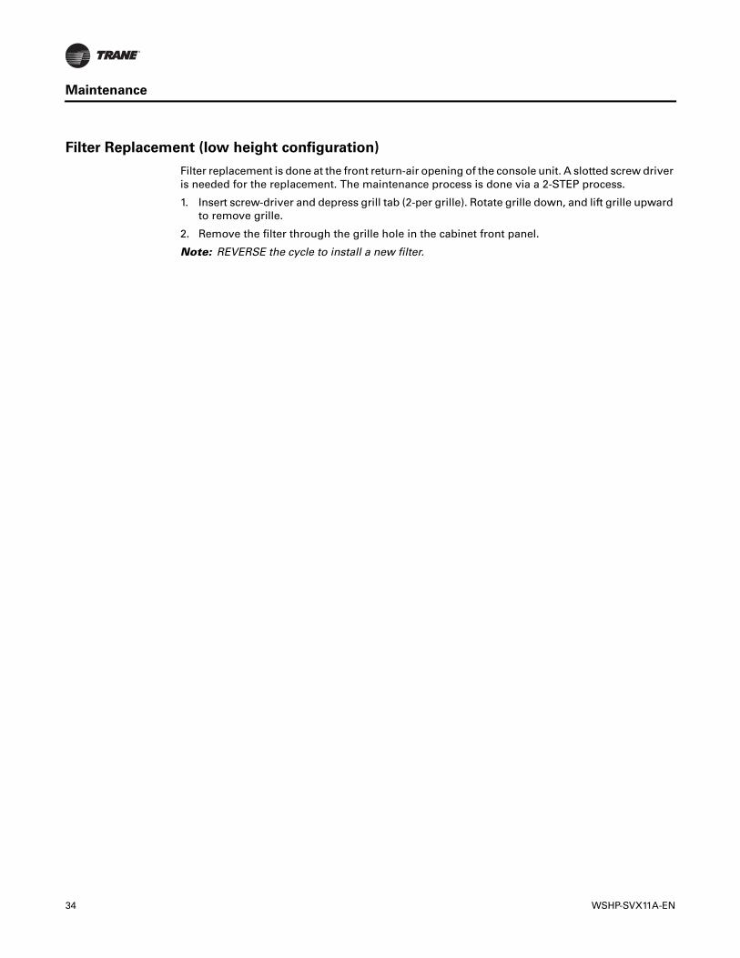
Filter Replacement (low height configuration)
Filter replacement is done at the front return-air opening of the console unit. A slotted screw driver is needed for the replacement. The maintenance process is done via a 2-STEP process.
1. Insert screw-driver and depress grill tab (2-per grille). Rotate grille down, and lift grille upward to remove grille.
2. Remove the filter through the grille hole in the cabinet front panel.
Note: REVERSE the cycle to install a new filter.

WSHP-SVX11A-EN 35
Troubleshooting
Problem Heating Cooling Cause CorrectionNo response to any thermostat setting
X X Main power off Check fuses
X X Defective control transformer Replace
X X Broken or loose connection Repair
X X Defective thermostat Replace
X X Transformer Reset Transformer
Unit short cycles X X Thermostat or sensor improperly located Relocate
X X Unit contains unit mounted thermostatChange jumper on thermostat from 2-degrees to 4-degrees
Blower runs, but compressor does not
X X Defective compressor overload Replace (if external)
X X Defective compressor contactor Replace
X X Supply Voltage too low Correct
X X Defective compressor capacitor Replace
X X Defective windings Replace
X X Limit switches open Check cause/Replace or repair
Insufficient capacity X X Dirty filter Replace/clean
X X Blower RPM too low Correct
X X Loss of conditioned air due to leaks in ductwork Repair leaks
X Introduction of excessively hot return-air Correct
X Introduction of excessively cold return-air Correct
X X Low on refrigerant charge Locate leak, repair and recharge by weight (not by superheat)
X X Restricted thermal expansion valve Replace
X X Defective reversing valve See WSHP-IOM-# for touch test chart
X X Thermostat improperly located Relocate
X X Unit undersized Recalculate heat gains/losses
X X Inadequate water flow Increase GPM
X X Scaling in heat exchanger Clean or replace
X Water too hot Decrease temperature
X Water too cold Increase temperature
High pressure switch X Inadequate GPM Increase water flow to unit
X Water too hot Decrease temperature
X Inadequate air flow Check, clean blower and coil
X Dirty filter Clean/replace
X X Overcharged with refrigerant Decrease charge
X X Defective pressure switch Check or replace
High head pressure X Trash in heat exchanger Backflush
X Low water flow Increase GPM
X X Overcharge of refrigerant Decrease charge
X X Non-condensable in system Evacuate and recharge by weight
X X Water too hot Decrease temperature
X Dirty filter Clean / replace
X Inadequate air flow Check, clean blower and coil
Low suction pressure X X Undercharged Locate leak, repair and recharge
X X Restricted thermal expansion valve Repair / replace
X Inadequate air flow Check, clean blower and coil
X Dirty filter Clean/replace
X Inadequate GPM Increase GPM
Low Pressure switch open
X Inadequate GPM Increase GPM
X Water too cold Increase temperature
X Inadequate air flow Increase CFM
X Dirty filter Clean/replace
X X Undercharged with refrigerant Increase charge
X X Defective pressure switch Replace
X X Heat transfer fluid too cold Raise water temperature

36 WSHP-SVX11A-EN
Troubleshooting
Deluxe Controls
Troubleshooting equipment containing the Deluxe Control option may be made easy by using the three light emitting diodes (LEDs). These LEDs are provided for indicating the operating mode of the controller. The LEDs are intended to aid in troubleshooting and unit maintenance. They are labeled on the circuit board with numbers as referenced in Table 9, p. 36.
Table 9. Diagnostic LED’s
Color: Green Color: Red
Controller ModeLED1 LED2 LED3
OFF OFF OFF Control OFF
ON OFF OFF Normal/Compressor OFF
ON OFF FLASH Anti-short cycle
ON OFF ON Normal/Compressor ON
FLASH ON OFF Brownout condition
ON FLASH ON Soft Lockout (low pressure)
ON FLASH FLASH Soft Lockout (high pressure)
ON ON ON Manual Lockout (low pressure)
ON ON FLASH Manual Lockout (high pressure)
ON FLASH OFF Manual Lockout (condensate overflow)
ON ON OFF Compressor Disable

WSHP-SVX11A-EN 37
Unit Wiring
Figure 15. Basic 115V/60Hz/1Ph

38 WSHP-SVX11A-EN
Unit Wiring
Figure 16. Basic 220-240V/50Hz/1Ph

WSHP-SVX11A-EN 39
Unit Wiring
Figure 17. Deluxe 230V/60Hz/1Ph
40 WSHP-SVX11A-EN
Unit Wiring
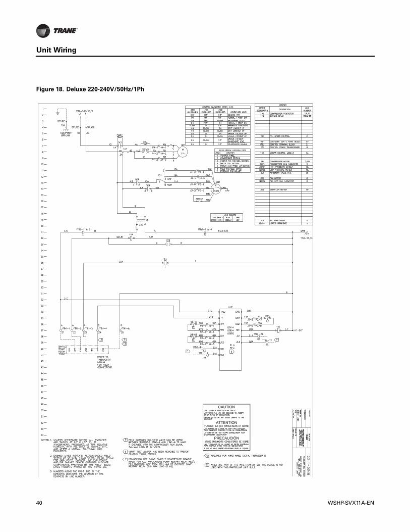
Figure 18. Deluxe 220-240V/50Hz/1Ph
WSHP-SVX11A-EN 41
Unit Wiring
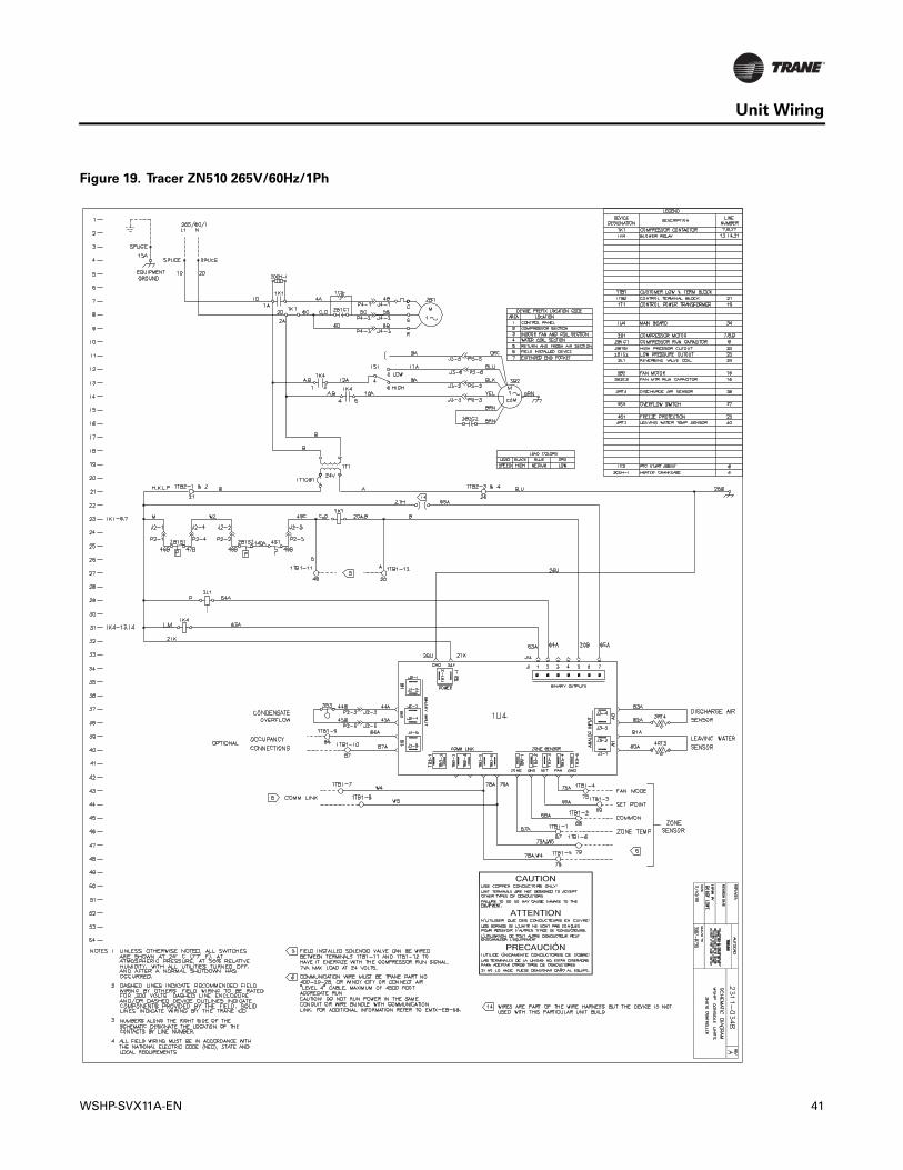
Figure 19. Tracer ZN510 265V/60Hz/1Ph

42 WSHP-SVX11A-EN
Unit Wiring
Figure 20. Tracer ZN510 220-240V/50Hz/1Ph

WSHP-SVX11A-EN 43
Warranty
Standard Warranty
The standard water-source heat pump warranty is Trane’s parts-only warranty, running 12 months from startup, not to exceed 18-months from shipment.
Extended Warranty
The optional extended warranty is a second through fifth year warranty. The time starts at the end of the standard 1-year coverage through the fifth year.
These extended warranties apply only to new equipment installed in domestic Worldwide Applied Systems Group sales territories and must be ordered prior to startup.
Trane optimizes the performance of homes and buildings around the world. A business of Ingersoll Rand, theleader in creating and sustaining safe, comfortable and energy efficient environments, Trane offers a broadportfolio of advanced controls and HVAC systems, comprehensive building services, and parts. For moreinformation, visit www.Trane.com.
Trane has a policy of continuous product and product data improvement and reserves the right to change design and specifications without notice.
We are committed to using environmentally
conscious print practices that reduce waste.
© 2011 Trane All rights reserved
WSHP-SVX11A-EN 15 Dec 2011
Supersedes WSHP-SVX11A-EN (May 2009)