Installation, Operation, and Maintenance for 3-10 Ton Packaged ...
44
SAFETY WARNING Only qualified personnel should install and service the equipment. The installation, starting up, and servicing of heating, ventilating, and air-conditioning equipment can be hazardous and requires specific knowledge and training. Improperly installed, adjusted or altered equipment by an unqualified person could result in death or serious injury. When working on the equipment, observe all precautions in the literature and on the tags, stickers, and labels that are attached to the equipment. Packaged Rooftop Air Conditioners Precedent™- Electric/Electric 5 – 10 Tons – 50 Hz September 2012 RT-SVX37B-EN Installation, Operation, and Maintenance Model Numbers TSC060ED - TSC120ED
Transcript of Installation, Operation, and Maintenance for 3-10 Ton Packaged ...

SAFETY WARNINGOnly qualified personnel should install and service the equipment. The installation, starting up, and servicing of heating, ventilating, and air-conditioning equipment can be hazardous and requires specific knowledge and training. Improperly installed, adjusted or altered equipment by an unqualified person could result in death or serious injury. When working on the equipment, observe all precautions in the literature and on the tags, stickers, and labels that are attached to the equipment.
Packaged Rooftop Air Conditioners
Precedent™- Electric/Electric
5 – 10 Tons – 50 Hz
September 2012 RT-SVX37B-EN
Installation, Operation,
and Maintenance
Model Numbers TSC060ED - TSC120ED
© 2012 Trane All rights reserved RT-SVX37B-EN
Warnings, Cautions and Notices
Warnings, Cautions and Notices. Note that warnings, cautions and notices appear at appropriate intervals throughout this manual. Warnings are provide to alert installing contractors to potential hazards that could result in death or personal injury. Cautions are designed to alert personnel to hazardous situations that could result in personal injury, while notices indicate a situation that could result in equipment or property-damage-only accidents.
Your personal safety and the proper operation of this machine depend upon the strict observance of these precautions.
Read this manual thoroughly before operating or servicing this unit.
ImportantEnvironmental Concerns!
Scientific research has shown that certain man-made chemicals can affect the earth’s naturally occurring stratospheric ozone layer when released to the atmosphere. In particular, several of the identified chemicals that may affect the ozone layer are refrigerants that contain Chlorine, Fluorine and Carbon (CFCs) and those containing Hydrogen, Chlorine, Fluorine and Carbon (HCFCs). Not all refrigerants containing these compounds have the same potential impact to the environment. Trane advocates the responsible handling of all refrigerants-including industry replacements for CFCs such as HCFCs and HFCs.
Responsible Refrigerant Practices!
Trane believes that responsible refrigerant practices are important to the environment, our customers, and the air conditioning industry. All technicians who handle refrigerants must be certified. The Federal Clean Air Act (Section 608) sets forth the requirements for handling, reclaiming, recovering and recycling of certain refrigerants and the equipment that is used in these service procedures. In addition, some states or municipalities may have additional requirements that
must also be adhered to for responsible management of refrigerants. Know the applicable laws and follow them.
Revision Summary
RT-SVX37B-EN (10 September 2012)
• MERV 8 filter with filter removal tool
• Stainless steel drain pan, condensate overflow switch
• Updated Model Number Description, Maintenance, Troubleshooting
ATTENTION: Warnings, Cautions and Notices appear at appropriate sections throughout this literature. Read these carefully:
WARNINGIndicates a potentially hazardous situation which, if not avoided, could result in death or serious injury.
CAUTIONsIndicates a potentially hazardous situation which, if not avoided, could result in minor or moderate injury. It could also be used to alert against unsafe practices.
NOTICE: Indicates a situation that could result in equipment or property-damage only
WARNING
Proper Field Wiring and Grounding Required!
All field wiring MUST be performed by qualified personnel. Improperly installed and grounded field wiring poses FIRE and ELECTROCUTION hazards. To avoid these hazards, you MUST follow requirements for field wiring installation and grounding as described in NEC and your local/state electrical codes. Failure to follow code could result in death or serious injury.
WARNING
Personal Protective Equipment (PPE) Required!
Installing/servicing this unit could result in exposure to electrical, mechanical and chemical hazards.
• Before installing/servicing this unit, technicians
MUST put on all Personal Protective Equipment (PPE)
recommended for the work being undertaken.
ALWAYS refer to appropriate MSDS sheets and OSHA
guidelines for proper PPE.
• When working with or around hazardous chemicals,
ALWAYS refer to the appropriate MSDS sheets and
OSHA guidelines for information on allowable
personal exposure levels, proper respiratory
protection and handling recommendations.
• If there is a risk of arc or flash, technicians MUST put
on all Personal Protective Equipment (PPE) in
accordance with NFPA 70E or other country-specific
requirements for arc flash protection, PRIOR to
servicing the unit.
Failure to follow recommendations could result in death or serious injury.
RT-SVX37B-EN 3
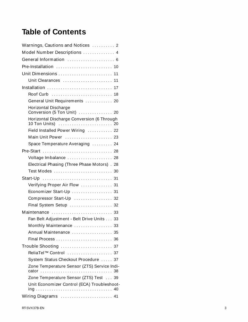
Table of Contents
Warnings, Cautions and Notices . . . . . . . . . . 2
Model Number Descriptions . . . . . . . . . . . . . . 4
General Information . . . . . . . . . . . . . . . . . . . . . 6
Pre-Installation . . . . . . . . . . . . . . . . . . . . . . . . . 10
Unit Dimensions . . . . . . . . . . . . . . . . . . . . . . . . 11
Unit Clearances . . . . . . . . . . . . . . . . . . . . . . 11
Installation . . . . . . . . . . . . . . . . . . . . . . . . . . . . . 17
Roof Curb . . . . . . . . . . . . . . . . . . . . . . . . . . . 18
General Unit Requirements . . . . . . . . . . . . 20
Horizontal Discharge Conversion (5 Ton Unit) . . . . . . . . . . . . . . . 20
Horizontal Discharge Conversion (6 Through 10 Ton Units) . . . . . . . . . . . . . . . . . . . . . . . . 20
Field Installed Power Wiring . . . . . . . . . . . 22
Main Unit Power . . . . . . . . . . . . . . . . . . . . . 23
Space Temperature Averaging . . . . . . . . . 24
Pre-Start . . . . . . . . . . . . . . . . . . . . . . . . . . . . . . . 28
Voltage Imbalance . . . . . . . . . . . . . . . . . . . . 28
Electrical Phasing (Three Phase Motors) . 28
Test Modes . . . . . . . . . . . . . . . . . . . . . . . . . . 30
Start-Up . . . . . . . . . . . . . . . . . . . . . . . . . . . . . . . 31
Verifying Proper Air Flow . . . . . . . . . . . . . . 31
Economizer Start-Up . . . . . . . . . . . . . . . . . . 31
Compressor Start-Up . . . . . . . . . . . . . . . . . 32
Final System Setup . . . . . . . . . . . . . . . . . . . 32
Maintenance . . . . . . . . . . . . . . . . . . . . . . . . . . . 33
Fan Belt Adjustment - Belt Drive Units . . . 33
Monthly Maintenance . . . . . . . . . . . . . . . . . 33
Annual Maintenance . . . . . . . . . . . . . . . . . . 35
Final Process . . . . . . . . . . . . . . . . . . . . . . . . . 36
Trouble Shooting . . . . . . . . . . . . . . . . . . . . . . . 37
ReliaTel™ Control . . . . . . . . . . . . . . . . . . . . 37
System Status Checkout Procedure . . . . . 37
Zone Temperature Sensor (ZTS) Service Indi-cator . . . . . . . . . . . . . . . . . . . . . . . . . . . . . . . . 38
Zone Temperature Sensor (ZTS) Test . . . 39
Unit Economizer Control (ECA) Troubleshoot-ing . . . . . . . . . . . . . . . . . . . . . . . . . . . . . . . . . . 40
Wiring Diagrams . . . . . . . . . . . . . . . . . . . . . . . 41

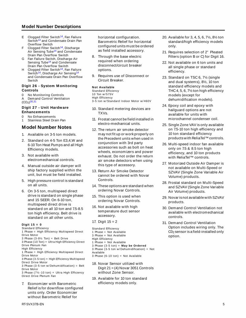
Model Number Descriptions
Digit 1 - Unit TypeT DX Cooling
Digit 2 - EfficiencyS Standard EfficiencyH High Efficiency
Digit 3 - AirflowC Convertible
Digit 4,5,6 - Nominal Gross Cooling Capacity (MBh)036 3 Ton048 4 Ton060 5 Ton072 6 Ton090 7½ Ton, Single Compressor092 7½ Ton, Dual Compressor102 8½ Ton120 10 Ton
Digit 7 - Major Design SequenceE R-410A RefrigerantF Microchannel Type Condenser
Coils23
Digit 8 - Voltage SelectionD 380-415/50/3
Digit 9 - Unit ControlsE ElectromechanicalR ReliaTel™ Microprocessor
Digit 10 - Heating Capacity
Digit 11 - Minor Design SequenceA First Sequence20
B Second Sequence19
Digit 12,13 - Service Sequence** Factory Assigned
Digit 14 - Fresh Air Selection0 No Fresh AirA Manual Outside Air Damper 0-50%4
B Motorized Outside Air Damper 0-50%27
C Economizer, Dry Bulb 0-100%without Barometric Relief7
D Economizer, Dry Bulb 0-100%with Barometric Relief7
E Economizer, Reference Enthalpy0-100% without Barometric Relief3,7
F Economizer, Reference Enthalpy0-100% with Barometric Relief3,7
G Economizer, ComparativeEnthalpy 0-100% withoutBarometric Relief3,7
H Economizer, ComparativeEnthalpy 0-100% with BarometricRelief3,7
Digit 15 - Supply Fan/Drive Type/Motor0 Standard Drive6
1 Oversized Motor2 Optional Belt Drive Motor17
6 Single Zone Variable Air Volume25
7 Multi-Speed Indoor Fan26
Digit 16 - Hinged Service Access/Filters0 Standard Panels/Standard FiltersA Hinged Access Panels/Standard
FiltersB Standard Panels/2” MERV 8 FiltersC Hinged Access Panels/2” MERV 8
FiltersD Standard Panels/2” MERV 13 FiltersE Hinged Access Panels/2” MERV 13
Filters
Digit 17 - Condenser Coil Protection0 Standard Coil1 Standard Coil with Hail Guard 2 Black Epoxy Pre-Coated Condenser
Coil24
3 Black Epoxy Pre-CoatedCondenser Coil with Hail Guard24
4 CompleteCoat™ Condenser Coil5 CompleteCoat™ Condenser Coil
with Hail Guard
Digit 18 - Through the Base Provisions0 No Through-the-Base ProvisionsA Through-the-Base Electric8
Digit 19 - Disconnect/Circuit Breaker (three-phase only)0 No Disconnect/No Circuit Breaker1 Unit Mounted Non-Fused
Disconnect82 Unit Mounted Circuit Breaker8
Digit 20 - Convenience Outlet0 No Convenience OutletA Unpowered Convenience OutletB Powered Convenience Outlet
(three-phase only)9
Digit 21 - Communications Options3
0 No Communications Interface1 Trane Communications Interface2 LonTalk® Communications Interface3 Novar 2024 Controls29
4 Novar 3051 Controls without ZoneSensor29
5 Novar 3051Controls Interface withDCV29
6 BACnet™ Communications Interface
Digit 22 - Refrigeration System Option0 Standard Refrigeration System10
B Dehumidification Option21,22
Digit 23 - Refrigeration ControlsNote: Applicable to Digit 7 = E, F0 No Refrigeration Control51 Frostat11,28
2 Crankcase Heater2
3 Frostat11,28 and Crankcase Heater2
Digit 24 - Smoke Detector16
0 No Smoke DetectorA Return Air Smoke Detector12,13
B Supply Air Smoke DetectorC Supply and Return Air Smoke
Detectors12,13
D Plenum Smoke Detector
Digit 25 - System Monitoring Controls0 No Monitoring Control14
1 Clogged Filter Switch14
2 Fan Failure Switch14
3 Discharge Air Sensing Tube14
4 Clogged Filter Switch and FanFailure Switch14
5 Clogged Filter Switch and DischargeAir Sensing Tube14
6 Fan Failure Switch and Discharge AirSensing Tube14
7 Clogged Filter Switch, Fan Failure Switch and Discharge AirSensing Tube14
8 Novar Return Air Sensor (NOVAR 2024)15,29
9 Novar Zone Temp Sensor (NOVAR 3051)18,29
A Condensate Drain Pan OverflowSwitch
B Clogged Filter Switch14 andCondensate Drain Pan OverflowSwitch
C Fan Failure Switch14 and CondensateDrain Pan Overflow Switch
D Discharge Air Sensing14 andCondensate Drain Pan Overflow Switch
T S C 0 6 0 E D R L A * *
1 2 3 4 5 6 7 8 9 10 11 12 13
0=No Electric Heat F=14 kW (1 phase)1
A=5 kW (1 phase)1 G=18 kW (1&3 phase)B=6 kW (3 phase) J=23 kW (3 phase)C=9 kW (3 phase) K= 27 kW (3 phase)D=10 kW (1 phase)1 N = 36 kW (3 phase)E=12 kW (3 phase) P = 54 kW (3 phase)
4 RT-SVX37B-EN
Model Number Descriptions
E Clogged Filter Switch14, Fan FailureSwitch14 and Condensate Drain Pan Overflow Switch
F Clogged Filter Switch14, DischargeAir Sensing Tube14 and CondensateDrain Pan Overflow Switch
G Fan Failure Switch, Discharge AirSensing Tube14 and CondensateDrain Pan Overflow Switch
H Clogged Filter Switch14, Fan Failure Switch14, Discharge Air Sensing14
and Condensate Drain Pan Overflow Switch
Digit 26 - System Monitoring Controls0 No Monitoring ControlsA Demand Control Ventilation (CO2)30,31
Digit 27 - Unit Hardware Enhancements0 No Enhancements1 Stainless Steel Drain Pan
Model Number Notes
1. Available on 3-5 ton models.
2. Standard on 4-5 Ton E3,4,W and 6-10 Ton Heat Pumps and all High Efficiency models.
3. Not available with electromechanical controls.
4. Manual outside air damper will ship factory supplied within the unit, but must be field installed.
5. High pressure control is standard on all units.
6. On 3-5 ton, multispeed direct drive is standard on single phase and 15 SEER. On 6-10 ton, multispeed direct drive is standard on all 10 ton and 7.5-8.5 ton high efficiency. Belt drive is standard on all other units.
7. Economizer with Barometric Relief is for downflow configured units only. Order Economizer without Barometric Relief for
horizontal configuration. Barometric Relief for horizontal configured units must be ordered as field installed accessory.
8. Through the base electric required when ordering disconnect/circuit breaker options.
9. Requires use of Disconnect or Circuit Breaker.
10. Standard metering devices are TXVs.
11. Frostat cannot be field installed in electro-mechanical units.
12. The return air smoke detector may not fit up or work properly on the Precedent units when used in conjunction with 3rd party accessories such as bolt on heat wheels, economizers and power exhaust. Do not order the return air smoke detectors when using this type of accessory.
13. Return Air Smoke Detector cannot be ordered with Novar Controls.
14. These options are standard when ordering Novar Controls.
15. This option is used when ordering Novar Controls.
16. Not available with high temperature duct sensor accessory.
17. Digit 15 = 2
18. Novar Sensor utilized with Digit 21 = (4) Novar 3051 Controls without Zone Sensor.
19. Available for 10 ton standard efficiency models only.
20. Available for 3, 4, 5, 6, 7½, 8½ ton standard/high efficiency models only.
21. Requires selection of 2” Pleated Filters (option B or C) for Digit 16.
22. Not available on 6 ton units and all single phase or standard efficiency.
23. Standard on TSC 6, 7½ (single and dual systems), 8½, 10 ton standard efficiency models and THC 4, 5, 6, 7½ ton high efficiency models (except for dehumidification models).
24. Epoxy coil and epoxy with hailguard options are not available for units with microchannel condenser coil.
25. Single Zone VAV is only available on 7.5-10 ton high efficiency and 10 ton standard efficiency products with ReliaTel™ controls.
26. Multi-speed indoor fan available only on 7.5 & 8.5 ton high efficiency, and 10 ton products with ReliaTel™ controls.
27. Motorized Outside Air Damper is not available on Multi-Speed or SZVAV (Single Zone Variable Air Volume) products.
28. Frostat standard on Multi-Speed and SZVAV (Single Zone Variable Air Volume) products.
29. Novar is not available with SZVAV products.
30. Demand Control Ventilation not available with electromechanical controls.
31. Demand Control Ventilation Option includes wiring only. The C02 sensor is a field-installed only option.
Digit 15 = 0Standard Efficiency1 Phase = High Efficiency Multispeed Direct Drive Motor3 Phase (3-8½ Ton) = Belt Drive3 Phase (10 Ton) = Ultra High Efficiency Direct Drive Plenum FanHigh Efficiency1 Phase = High Efficiency Multispeed Direct Drive Motor3 Phase (3-5 ton) = High Efficiency Multispeed Direct Drive Motor3 Phase (3-5 ton w/Dehumidification) = Belt Drive Motor3 Phase (7½-10 ton) = Ultra High Efficiency Direct Drive Plenum Fan
Not AvailableStandard Efficiency10 Ton w/575VHigh Efficiency3-5 ton w/Standard Indoor Motor w/460V
Standard Efficiency1 Phase = Not Available3 Phase = Not AvailableHigh Efficiency1 Phase = Not Available3 Phase (3-5 ton) = May be Ordered3 Phase (3-5 ton w/Dehumidification) = Not Available3 Phase (6-10 ton) = Not Available
RT-SVX37B-EN 5
General Information
Unit Inspection
As soon as the unit arrives at the job site
• Verify that the nameplate data matches the data on the sales order and bill of lading (including electrical data).
• Verify that the power supply complies with the unit nameplate specifications.
• Visually inspect the exterior of the unit, including the roof, for signs of shipping damage.
If the job site inspection of the unit reveals damage or material shortages, file a claim with the carrier immediately. Specify the type and extent of the damage on the “bill of lading” before signing.
• Visually inspect the internal components for shipping damage as soon as possible after delivery and before it is stored. Do not walk on the sheet metal base pans.
• If concealed damage is discovered, notify the carrier’s terminal of damage immediately by phone and by mail. Concealed damage must be reported within 15 days.
• Request an immediate joint inspection of the damage by the carrier and the consignee. Do not remove damaged material from the receiving location. Take photos of the damage, if possible. The owner must provide reasonable evidence that the damage did not occur after delivery.
• Notify the appropriate sales representative before installing or repairing a damaged unit.
Storage
Take precautions to prevent condensate from forming inside the unit’s electrical compartments and motors if:
1. the unit is stored before it is installed; or,
2. the unit is set on the roof curb, and temporary heat is provided in the building. Isolate all side panel service entrances and base pan openings (e.g., conduit holes, S/A and R/A openings, and flue openings) from the ambient air until the unit is ready for start-up.
Note: Do not use the unit’s heater for temporary heat without first completing the start-up procedure detailed under “Starting the Unit”.
The manufacturer will not assume any responsibility for equipment damage resulting from condensate accumulation on the unit’s electrical and/or mechanical components.
Model Number Description
All products are identified by a multiple-character model number that precisely identifies a particular type of unit. Its use will enable the owner/operator, installing contractors, and service engineers to define the operation, specific components, and other options for any specific unit.
When ordering replacement parts or requesting service, be sure to refer to the specific model number and serial number printed on the unit nameplate.
Overview of Manual
Note: One copy of this document ships inside the control panel of each unit and is customer property. It must be retained by the unit’s maintenance personnel.
This booklet describes proper installation, operation, and maintenance procedures for air cooled systems. By carefully reviewing the information within this manual and following the instructions, the risk of improper operation and/or component damage will be minimized.
It is important that periodic maintenance be performed to help assure trouble free operation. A maintenance schedule is provided at the end of this manual. Should equipment failure occur, contact a qualified service organization with qualified, experienced HVAC technicians to properly diagnose and repair this equipment.
Unit Nameplate
A Mylar unit nameplate is located on the unit’s corner support next to the filter access panel. It includes the unit model number, serial number, electrical characteristics, refrigerant charge, as well as other pertinent unit data.
Compressor Nameplate
The nameplate for the compressors are located on the side of the compressor.
Unit Description
Before shipment, each unit is leak tested, dehydrated, charged with refrigerant and compressor oil, and run tested for proper control operation.
The condenser coils are aluminum fin, mechanically bonded to copper tubing.
Direct-drive, vertical discharge condenser fans are provided with built-in thermal overload protection.
The ReliaTel™ Control Module is a microelectronic control system that is referred to as “Refrigeration Module” (RTRM). The acronym RTRM is used extensively throughout this document when referring to the control system network.
These modules through Proportional/Integral control algorithms perform specific unit functions that governs unit operation in response to; zone temperature, supply air temperature, and/or humidity conditions depending on the application. The stages of capacity control for these units are achieved by starting and stopping the compressors.
The RTRM is mounted in the control panel and is factory wired to the respective internal components. The RTRM receives and interprets information from other unit
6 RT-SVX37B-EN
General Information
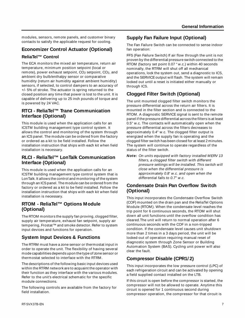
modules, sensors, remote panels, and customer binary contacts to satisfy the applicable request for cooling.
Economizer Control Actuator (Optional)
ReliaTel™ Control
The ECA monitors the mixed air temperature, return air temperature, minimum position setpoint (local or remote), power exhaust setpoint, CO2 setpoint, CO2, and ambient dry bulb/enthalpy sensor or comparative humidity (return air humidity against ambient humidity) sensors, if selected, to control dampers to an accuracy of +/- 5% of stroke. The actuator is spring returned to the closed position any time that power is lost to the unit. It is capable of delivering up to 25 inch pounds of torque and is powered by 24 VAC.
RTCI - ReliaTel™ Trane Communication Interface (Optional)
This module is used when the application calls for an ICSTM building management type control system. It allows the control and monitoring of the system through an ICS panel. The module can be ordered from the factory or ordered as a kit to be field installed. Follow the installation instruction that ships with each kit when field installation is necessary.
RLCI - ReliaTel™ LonTalk Communication Interface (Optional)
This module is used when the application calls for an ICSTM building management type control system that is LonTalk. It allows the control and monitoring of the system through an ICS panel. The module can be ordered from the factory or ordered as a kit to be field installed. Follow the installation instruction that ships with each kit when field installation is necessary.
RTOM - ReliaTel™ Options Module (Optional)
The RTOM monitors the supply fan proving, clogged filter, supply air temperature, exhaust fan setpoint, supply air tempering, Frostat™ and smoke detector. Refer to system input devices and functions for operation.
System Input Devices & Functions
The RTRM must have a zone sensor or thermostat input in order to operate the unit. The flexibility of having several mode capabilities depends upon the type of zone sensor or thermostat selected to interface with the RTRM.
The descriptions of the following basic input devices used within the RTRM network are to acquaint the operator with their function as they interface with the various modules. Refer to the unit’s electrical schematic for the specific module connections.
The following controls are available from the factory for field installation.
Supply Fan Failure Input (Optional)
The Fan Failure Switch can be connected to sense indoor fan operation:
FFS (Fan Failure Switch) If air flow through the unit is not proven by the differential pressure switch connected to the RTOM (factory set point 0.07 “w.c.) within 40 seconds nominally, the RTRM will shut off all mechanical operations, lock the system out, send a diagnostic to ICS, and the SERVICE output will flash. The system will remain locked out until a reset is initiated either manually or through ICS.
Clogged Filter Switch (Optional)
The unit mounted clogged filter switch monitors the pressure differential across the return air filters. It is mounted in the filter section and is connected to the RTOM. A diagnostic SERVICE signal is sent to the remote panel if the pressure differential across the filters is at least 0.5" w.c. The contacts will automatically open when the pressure differential across the filters decreases to approximately 0.4" w.c. The clogged filter output is energized when the supply fan is operating and the clogged filter switch has been closed for at least 2 minutes. The system will continue to operate regardless of the status of the filter switch.
Note: On units equipped with factory installed MERV 13 filters, a clogged filter switch with different pressure settings will be installed. This switch will close when the differential pressure is approximately 0.8' w.c. and open when the differential falls to 0.7" w.c.
Condensate Drain Pan Overflow Switch (Optional)
This input incorporates the Condensate Overflow Switch (COF) mounted on the drain pan and the ReliaTel Options Module (RTOM). When the condensate level reaches the trip point for 6 continuous seconds, the RTOM will shut down all unit functions until the overflow condition has cleared.The unit will return to normal operation after 6 continuous seconds with the COF in a non-tripped condition. If the condensate level causes unit shutdown more than 2 times in a 3 days period, the unit will be locked-out of operation requiring manual reset of diagnostic system through Zone Sensor or Building Automation System (BAS). Cycling unit power will also clear the fault.
Compressor Disable (CPR1/2)
This input incorporates the low pressure control (LPC) of each refrigeration circuit and can be activated by opening a field supplied contact installed on the LTB.
If this circuit is open before the compressor is started, the compressor will not be allowed to operate. Anytime this circuit is opened for 1 continuous second during compressor operation, the compressor for that circuit is
RT-SVX37B-EN 7

General Information
immediately turned “Off”. The compressor will not be allowed to restart for a minimum of 3 minutes should the contacts close.
If four consecutive open conditions occur during the first three minutes of operation, the compressor for that circuit will be locked out, a diagnostic communicated to the remote panel (if installed), and a manual reset will be required to restart the compressor.
Low Pressure Control
ReliaTel Control
When the LPC is opened for 1 continuous second, the compressor for that circuit is turned off immediately. The compressor will not be allowed to restart for a minimum of 3 minutes.
If four consecutive open conditions occur during an active call for cooling, the compressor will be locked out, a diagnostic communicated to ICS™, if applicable, and a manual reset required to restart the compressor. On dual compressor units only the affected compressor circuit is locked out.
High Pressure Control
ReliaTel Control
The high pressure controls are wired in series between the compressor outputs on the RTRM and the compressor contactor coils. If the high pressure control switch opens, the RTRM senses a lack of current while calling for cooling and locks the compressor out.
If four consecutive open conditions occur during an active call for cooling, the compressor will be locked out, a diagnostic communicated to ICS™, if applicable, and a manual reset required to restart the compressor. On dual compressor units only the affected compressor circuit is locked out.
Lead/Lag Control (Dual Circuit Only)
ReliaTel Control Only
Lead/Lag is a selectable input located on the RTRM. The RTRM is configured from the factory with the Lead/Lag control disabled. To activate the Lead/Lag function, simply cut the wire connected to J3-8 at the RTRM. When it is activated, each time the designated lead compressor is shut off due to the load being satisfied, the lead compressor or refrigeration circuit switches. When the RTRM is powered up, i.e. after a power failure, the control will default to the number one circuit compressor.
Zone Sensor Module (ZSM) (BAYSENS106*)
This electronic sensor features three system switch settings (Heat, Cool, and Off) and two fan settings (On
and Auto). It is a manual changeover control with single setpoint. (Cooling Setpoint Only)
Zone Sensor Module (ZSM) (BAYSENS108*)
This electronic sensor features four system switch settings (Heat, Cool, Auto, and Off) and two fan settings (On and Auto). It is a manual or auto changeover control with dual setpoint capability. It can be used with a remote zone temperature sensor BAYSENS017B.
Zone Sensor (BAYSENS110*)
This electronic sensor features four system switch settings (Heat, Cool, Auto, and Off) and two fan settings (On and Auto) with four system status LED’s. It is a manual or auto changeover control with dual setpoint capability. It can be used with a remote zone temperature sensor BAYSENS017B.
Programmable Zone Sensor - (BAYSENS119*)
This 7 day programmable sensor features 2, 3 or 4 periods for Occupied or Unoccupied programming per day. If the power is interrupted, the program is retained in permanent memory. If power is off for an extended period of time, only the clock and day may have to be reset.
The Zone Sensor allows selection of 2, 3 or 4 system modes (Heat, Cool, Auto, and Off), two fan modes (On and Auto). It has dual temperature selection with programmable start time capability.
The occupied cooling set point ranges between 45 and 98 degrees Fahrenheit. The heating set point ranges between 43 and 96 degrees Fahrenheit.
A liquid crystal display (LCD) displays zone temperature, temperature set points, day of the week, time, and operational mode symbols.
The Option Menu is used to enable or disable applicable functions, i.e.; Morning Warm-up, Economizer minimum position override during unoccupied status, Fahrenheit or Centigrade, Supply air tempering, Remote zone temperature sensor, 12/24 hour time display, Smart fan, and Computed recovery.
During an occupied period, an auxiliary relay rated for 1.25 amps @ 30 volts AC with one set of single pole double throw contacts is activated.
Status Inputs (4 Wires Optional)
The ZSM can be wired to receive four (4) operating status signals from the RTRM (HEAT, COOL, SYSTEM “ON”, SER-VICE).
Four (4) wires from the RTRM should be connected to the appropriate terminals (7, 8, 9 & 10) on the ZSM.
Remote Zone Sensor (BAYSENS073*)
This electronic sensor features remote zone sensing and timed override with override cancellation. It is used with a Trane Integrated Comfort™ building management system.
8 RT-SVX37B-EN

General Information
Remote Zone Sensor (BAYSENS074*)
This electronic sensor features single setpoint capability and timed override with override cancellation. It is used with a Trane Integrated Comfort™ building management system.
Remote Zone Sensor (BAYSENS016A)
This bullet type temperature sensor can be used for; outside air (ambient) sensing, return air temperature sensing, supply air temperature sensing, remote temperature sensing (uncovered. Wiring procedures vary according to the particular application and equipment involved. Refer to the unit’s wiring diagrams for proper connections.
Remote Zone Sensor (BAYSENS077*)
This electronic sensor can be used with BAYSENS006B, 008B, 010B, 019B Remote Panels. When this sensor is wired to a BAYSENS019B Remote Panel, wiring must be 18 AWG Shielded Twisted Pair (Belden 8760 or equivalent). Refer to The specific Remote Panel for wiring details.
Wireless Zone Sensor (BAYSENS050)
This electronic sensor features five system settings (Auto, Off, Cool, Heat, and Emergency Heat) and with On and Auto fan settings. It is a manual or auto changeover control with dual setpoint capability. Other features include a timed override function, lockable system settings, and Fahrenheit or Celsius temperature display. Included with the wireless zone sensor will be a receiver that is to be mounted inside the unit, a mounting bracket, and a wire harness.
High Temperature Sensor (BAYFRST001A)
This sensor connects to the RTRM Emergency Stop Input on the LTB and provides high limit “shutdown” of the unit. The sensor is used to detect high temperatures due to fire in the air conditioning or ventilation ducts. The sensor is designed to mount directly to the sheet metal duct. Each kit contains two sensors. The return air duct sensor (X1310004001) is set to open at 135ºF. The supply air duct sensor (X1310004002) is set to open at 240ºF. The control can be reset after the temperature has been lowered approximately 25ºF below the cutout setpoint.
Evaporator Frost Control (ReliaTel™ Option)
This input incorporates the Frostat™ control (FOS) mounted in the indoor coil circuit and can be activated by closing a field supplied contact installed in parallel with the FOS.
If this circuit is open before the compressor is started, the compressor will not be allowed to operate. Anytime this circuit is opened for 1 continuous second during compressor operation, the compressor for that circuit is immediately turned “Off”. The compressor will not be
allowed to restart for a minimum of 3 minutes should the FOS close.
Discharge Line Temp Switch (DLTS)
The DLTS is looped in series with HPC and LPC. It prevents compressor from overheating (over 300ºF dome temp) in case of ID fan failure (cooling) or OD fan failure (heating).
Phase Monitor
This sensor monitors voltage between the 3 conductors of the 3 phase power supply. Two LED lights are provided. The green light indicates that a balanced 3 phase supply circuit is properly connected. The red light indicates that unit operation has been prevented. There are two conditions that will prevent unit operation.The power supply circuit is not balanced with the proper phase sequence of L1, L2, L3 for the 3 conductors of a 3 phase circuit. The line to line voltage is not between 180 volts and 633 volts
RT-SVX37B-EN 9

10 RT-SVX37B-EN
Pre-Installation
Precautionary Measures
• Avoid breathing fiberglass dust.
• Use a NIOSH approved dust/mist respirator.
• Avoid contact with the skin or eyes. Wear long-sleeved, loose-fitting clothing, gloves, and eye protection.
• Wash clothes separately from other clothing: rinse washer thoroughly.
• Operations such as sawing, blowing, tear-out, and spraying may generate fiber concentrations requiring additional respiratory protection. Use the appropriate NIOSH approved respiration in these situations.
First Aid Measures
Eye Contact - Flush eyes with water to remove dust. If symptoms persist, seek medical attention.
Skin Contact - Wash affected areas gently with soap and warm water after handling.
Heater Inspection
Remove power to the unit and gain access to the electric heat elements by removing the horizontal supply cover. Visually inspect the heater elements for the following.
• Elements that are no longer secured to the white ceramic insulator.
• Elements touching each other or touching metal.
• Severely kinked, drooping, or broken elements.
If an element has detached from its ceramic insulator, carefully put it back into place.
Replace the heater elements if they present symptoms noted in item 2 or 3 above.
WARNING
Fiberglass Wool!
Product contains fiberglass wool. Disturbing the insulation in this product during installation, maintenance or repair will expose you to airborne particles of glass wool fibers and ceramic fibers known to the state of California to cause cancer through inhalation. Glass wool fibers may also cause respiratory, skin or eye irritation.
WARNING
Hazardous Voltage!
Disconnect all electric power, including remote disconnects before servicing. Follow proper lockout/tagout procedures to ensure the power can not be inadvertently energized. Failure to disconnect power before servicing could result in death or serious injury.

Unit Dimensions
Unit Clearances
Figure 1 illustrates the minimum operating and service clearances for either a single or multiple unit installation. These clearances are the minimum distances necessary to
assure adequate serviceability, cataloged unit capacity, and peak operating efficiency.
Providing less than the recommended clearances may result in condenser coil starvation, “short-circuiting” of exhaust and economizer airflows, or recirculation of hot condenser air.
Figure 1. Typical installation clearances for single & multiple unit applications
TSC060E unitTSC060E unit TSC072-120E unitsTSC072-120E units
RT-SVX37B-EN 11
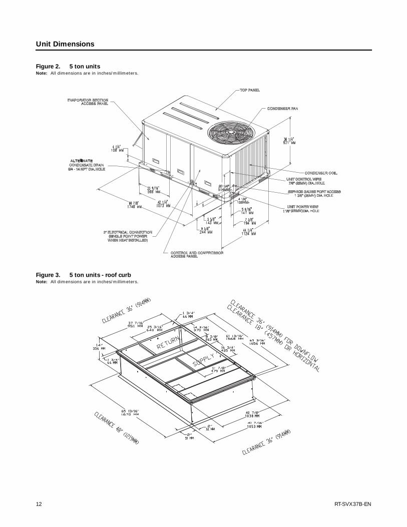
Unit Dimensions
Figure 2. 5 ton unitsNote: All dimensions are in inches/millimeters.
Figure 3. 5 ton units - roof curbNote: All dimensions are in inches/millimeters.
7
4444 MMMM
4444 MMMM
10381038 MMMM
10531053 MMMM
12 RT-SVX37B-EN
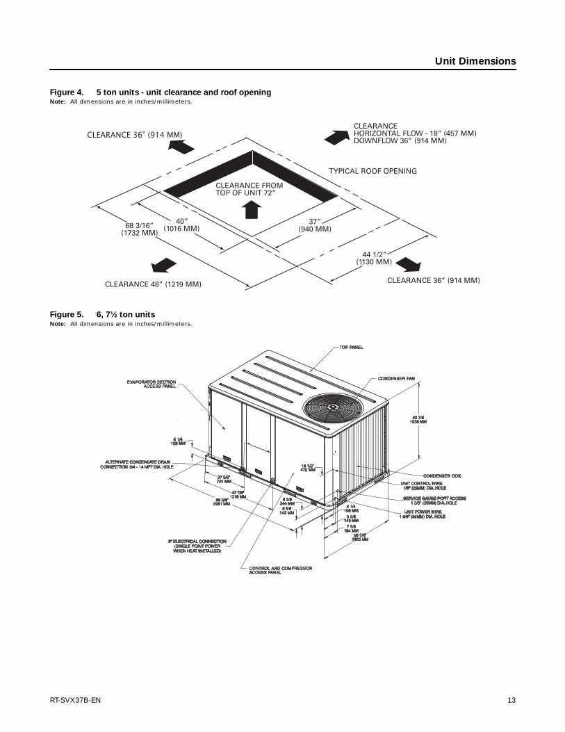
Unit Dimensions
Figure 4. 5 ton units - unit clearance and roof openingNote: All dimensions are in inches/millimeters.
CLEARANCE 36” (914 MM)
Figure 5. 6, 7½ ton unitsNote: All dimensions are in inches/millimeters.
RT-SVX37B-EN 13

Unit Dimensions
Figure 6. 6, 7½ ton units - roof curbNote: All dimensions are in inches/millimeters.
(2130 MM)(356 MM)
Figure 7. 6, 7½ ton units - unit clearance and roof openingNote: All dimensions are in inches/millimeters.
14 RT-SVX37B-EN
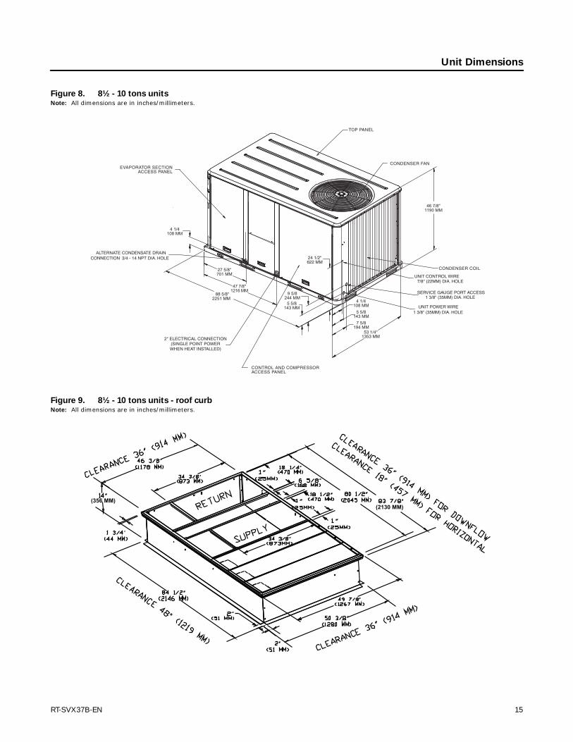
Unit Dimensions
Figure 8. 8½ - 10 tons unitsNote: All dimensions are in inches/millimeters.
Figure 9. 8½ - 10 tons units - roof curbNote: All dimensions are in inches/millimeters.
(2130 MM)(356 MM)
RT-SVX37B-EN 15

Unit Dimensions
Figure 10. 8½ - 10 tons units - unit clearance and roof openingNote: All dimensions are in inches/millimeters.
16 RT-SVX37B-EN

Installation
WARNING
Heavy Objects!
Do not use cables (chains or slings) except as shown. Each of the cables (chains or slings) used to lift the unit must be capable of supporting the entire weight of the unit. Lifting cables (chains or slings) may not be of the same length. Adjust as necessary for even unit lift. Other lifting arrangements may cause equipment or property-only damage. Failure to properly lift unit could result in death or serious injury.
WARNING
Improper Unit Lift!
Test lift unit approximately 24 inches to verify proper center of gravity lift point. To avoid dropping of unit, reposition lifting point if unit is not level. Failure to properly lift unit could result in death or serious injury or possible equipment or property-only damage.
Figure 11. Corner weights
Figure 12. Rigging and center of gravity
Table 1. Factory installed options (fiops)/accessory net weights (lbs/kgs)(a),(b)
(a) Weights for options not listed are <5 lbs (3kgs).(b) Net weight should be added to unit weight when ordering factory-in-
stalled accessories.
TSC060ED TSC072E-120ED
Net Weight Net Weight
Accessory 5 Ton 6-10 Ton
Barometric Relief 7/3 10/5
Coil Guards 12/5 20/9
Economizer 26/12 36/16
Hinged Doors 10/5 12/5
Manual Outside Air Damper 16/7 26/12
Motorized Outside Air Damper 20/9 30/14
Oversized Motor - 8/4
Roof Curb 61/28 78/35
Table 2. Maximum unit & corner weights (lbs/kgs) and center of gravity dimensions (in./mm) - cooling models
TonsUnit
Model No.
Maximum Model Weights(a)(lbs/kgs) Corner Weights(b)(lbs/kgs)
Center of Gravity (in./mm)
Shipping Net A B C D Length Width
5 TSC060ED 633/288 528/240 167/76 128/58 108/49 125/59 40/1006 597/23
6 TSC072ED 915/415 783/355 281/127 192/87 143/65 167/76 38/963 535/21
7½ TSC090ED 956/434 824/374 331/150 181/82 144/65 168/76 35/889 512/20
8½ TSC102ED 1054/478 916/415 307/139 257/117 156/79 195/89 40/1015 520/20
10 TSC120ED 1078/489 940/426 326/ 148 244/111 175/71 196/88 40/1003 532/21
(a) Weights are approximate.(b) Corner weights are given for information only.
RT-SVX37B-EN 17

Installation
Foundation
Horizontal Units
If the unit is installed at ground level, elevate it above the snow line. Provide concrete footings at each support location with a “full perimeter” support structure or a slab foundation for support. Refer to Table 2, p. 17 for the unit’s operating and point loading weights when constructing a footing foundation.
If anchoring is required, anchor the unit to the slab using hold down bolts or isolators. Isolators should be installed to minimize the transmission of vibrations into the building.
For rooftop applications, ensure the roof is strong enough to support the combined unit and support structural weight. Refer to Table 2, p. 17 for the unit operating weights. If anchoring is required, anchor the unit to the roof with hold-down bolts or isolators.
Check with a roofing contractor for proper waterproofing procedures.
Ductwork
Figure 13, p. 18 to Figure 14, p. 18 illustrate the supply and return air openings as viewed from the rear of the unit.
Figure 15 and Figure 16 illustrate the supply and return air openings in a downflow configuration.
Elbows with turning vanes or splitters are recommended to minimize air noise due to turbulence and to reduce static pressure.
When attaching the ductwork to the unit, provide a water tight flexible connector at the unit to prevent operating sounds from transmitting through the ductwork.
All outdoor ductwork between the unit and the structure should be weather proofed after installation is completed.
Roof Curb
Down flow
The roof curbs for these units consists of a “full perimeter” enclosure to support the unit just inside of the unit base rail.
Figure 13. 5 ton units - Horizontal supply & return air
openings
Figure 14. 6 - 10 ton units - Horizontal supply & return
air openings
Supply
Return
Figure 15. 5 ton units - Down flow supply & return air
openings w/ through the base utilities
Figure 16. 6 - 10 ton units - Down flow supply & return
air openings w/ through the base utilities
18 RT-SVX37B-EN
Installation
Before installing any roof curb, verify;
• it is the correct curb for the unit,
• it includes the necessary gaskets and hardware,
• the purposed installation location provides the required clearance for proper operation,
• the curb is level and square. The top surface of the curb must be true to assure an adequate curb-to-unit seal.
Verify that appropriate materials were used in the construction of roof and ductwork. Combustible materials should not be used in the construction of ductwork or roof curb that is in close proximity to heater elements or any hot surface. Any combustible material on the inside of the unit base should be removed and replaced with appropriate material.
Step-by-step curb assembly and installation instructions ship with each accessory roof curb kit. Follow the instructions carefully to assure proper fit-up when the unit is set into place.
Note: To ensure proper condensate flow during operation, as well as proper operation of the condensate overflow switch (if equipped), the unit and curb must be level.
If the unit is elevated, a field constructed catwalk around the unit is strongly recommended to provide easy access for unit maintenance and service.
Recommendations for installing the Supply Air and Return Air ductwork joining the roof curb are included in the curb instruction booklet. Curb ductwork must be fabricated and installed by the installing contractor before the unit is set into place.
Note: For sound consideration, cut only the holes in the roof deck for the ductwork penetrations. Do not cut out the entire roof deck within the curb perimeter.
If a Curb Accessory Kit is not used:
• The ductwork can be attached directly to the factory-provided flanges around the unit’s supply and return air openings. Be sure to use flexible duct connections at the unit.
• For “built-up” curbs supplied by others, gaskets must be installed around the curb perimeter flange and the supply and return air opening flanges.
Rigging
A Rigging illustration and Center-of-Gravity dimensional data table is shown in Figure 12, p. 17. Refer to the typical unit operating weights table before proceeding.
1. Remove all drill screws fastening wood protection to metal baserail. Remove all screws securing wooden protection to wooden top crate.
2. Remove Wooden Top Crate.
3. Rig the unit as shown in Figure 12, p. 17. Attach adequate strength lifting slings to all four lifting brackets in the unit base rail. Do not use cables, chains, or slings except as shown.
4. Install a lifting bar, as shown in Figure 12, p. 17, to protect the unit and to facilitate a uniform lift. The minimum distance between the lifting hook and the top of the unit should be 7 feet.
5. Test-lift the unit to ensure it is properly rigged and balanced, make any necessary rigging adjustments.
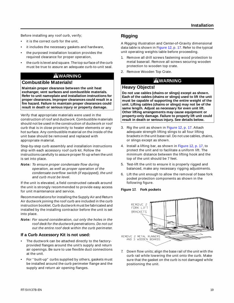
6. Lift the unit enough to allow the removal of base fork pocket protection components as shown in the following figure.
7. Down flow units; align the base rail of the unit with the curb rail while lowering the unit onto the curb. Make sure that the gasket on the curb is not damaged while positioning the unit.
WARNING
Combustible Materials!
Maintain proper clearance between the unit heat exchanger, vent surfaces and combustible materials. Refer to unit nameplate and installation instructions for proper clearances. Improper clearances could result in a fire hazard. Failure to maintain proper clearances could result in death or serious injury or property damage.
WARNING
Heavy Objects!
Do not use cables (chains or slings) except as shown. Each of the cables (chains or slings) used to lift the unit must be capable of supporting the entire weight of the unit. Lifting cables (chains or slings) may not be of the same length. Adjust as necessary for even unit lift. Other lifting arrangements may cause equipment or property-only damage. Failure to properly lift unit could result in death or serious injury. See details below.
Figure 17. Fork pockets
RT-SVX37B-EN 19
Installation
General Unit Requirements
The checklist listed below is a summary of the steps required to successfully install a commercial unit. This checklist is intended to acquaint the installing personnel with what is required in the installation process. It does not replace the detailed instructions called out in the applicable sections of this manual.
• Check the unit for shipping damage and material shortage; file a freight claim and notify appropriate sales representative.
• Verify correct model, options and voltage from unit nameplate.
• Verify that the installation location of the unit will provide the required clearance for proper operation.
• Assemble and install the roof curb (if applicable). Refer to the latest edition of the curb installers guide that ships with each curb kit.
• Fabricate and install ductwork; secure ductwork to curb.
• Install pitch pocket for power supply through building roof. (If applicable)
• Rigging the unit.
• Set the unit onto the curb; check for levelness.
• Ensure unit-to-curb seal is tight and without buckles or cracks.
• Install and connect a condensate drain line to the evaporator drain connection.
Note: Condensate Overflow Switch (if equipped) will not work if unit is not level properly.
Factory Installed Economizer
• Ensure the economizer has been pulled out into the operating position. Refer to the economizer installers guide for proper position and setup.
• Install all access panels.
Horizontal Discharge Conversion (5 Ton Unit)
Supplies Needed by Installer for Conversion: 3 oz. tube of High Temperature RTV sealant. (500°F / 260°C: Similar to Dow Corning 736)
Note: Failure to use recommended sealant could result in unit performance loss.
If a unit is to be converted to a Horizontal discharge, the following conversion must be performed:
1. Remove RETURN and SUPPLY duct covers.
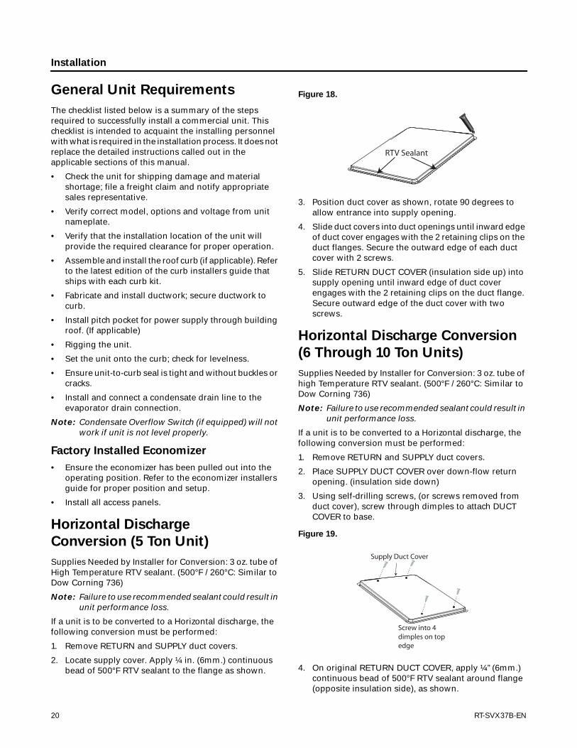
2. Locate supply cover. Apply ¼ in. (6mm.) continuous bead of 500°F RTV sealant to the flange as shown.
3. Position duct cover as shown, rotate 90 degrees to allow entrance into supply opening.
4. Slide duct covers into duct openings until inward edge of duct cover engages with the 2 retaining clips on the duct flanges. Secure the outward edge of each duct cover with 2 screws.
5. Slide RETURN DUCT COVER (insulation side up) into supply opening until inward edge of duct cover engages with the 2 retaining clips on the duct flange. Secure outward edge of the duct cover with two screws.
Horizontal Discharge Conversion
(6 Through 10 Ton Units)
Supplies Needed by Installer for Conversion: 3 oz. tube of high Temperature RTV sealant. (500°F / 260°C: Similar to Dow Corning 736)
Note: Failure to use recommended sealant could result in unit performance loss.
If a unit is to be converted to a Horizontal discharge, the following conversion must be performed:
1. Remove RETURN and SUPPLY duct covers.
2. Place SUPPLY DUCT COVER over down-flow return opening. (insulation side down)
3. Using self-drilling screws, (or screws removed from duct cover), screw through dimples to attach DUCT COVER to base.
4. On original RETURN DUCT COVER, apply ¼”(6mm.) continuous bead of 500°F RTV sealant around flange (opposite insulation side), as shown.
Figure 18.
Figure 19.
RTV Sealant
Supply Duct Cover
Screw into 4dimples on top edge
20 RT-SVX37B-EN

Installation
5. Slide RETURN DUCT COVER (insulation side up) into supply opening until inward edge of duct cover engages with the 2 retaining clips on the duct flange. Secure outward edge of the duct cover with two screws.
Note: If unit is equipped with Return Air Smoke Detector, refer to field conversion instructions for horizontal discharge before installing return air duct.
Note: If unit is equipped with Discharge Air Sensing option refer to the following figure for proper tube positioning based on unit tonnage.
Low Voltage Wiring (AC & DC) Requirements
• Install the zone thermostat, with or without switching subbase.
• Connect properly sized control wiring to the proper termination points between the zone thermostat and the unit control panel.
Condensate Drain Configuration
An evaporator condensate drain connection is provided on each unit. Refer to Figure 13, p. 18 and Figure 14, p. 18 for the appropriate drain location.
The condensate drain pan is factory installed to drain condensate to the back side of the unit. See Figure 13, p. 18 and Figure 14, p. 18. It can be converted to drain condensate out the front side of the unit or through the base.
To convert drain condensate out the front of
unit:
1. Remove evaporator access panel and supply air access panels.
2. Remove the support panel that the condensate drain pan exits through.
3. Slide the condensate drain pan out of the unit and rotate 180°.
4. Slide the condensate drain pan back into the unit, align the drain with the grommeted opening in the rear support panel and push until the coupling is seated in the grommet.
5. Replace the front support panel by aligning the panel with tabs in the raceway. Align the condensate drain pan support in the grommeted hole as the panel is put in place.
6. Replace evaporator access panel and supply air access panels.
Figure 20.
Figure 21.
RTV Sealant
Downflow application
Horizontal application
Cap assemblywith insulation
Figure 22. Duct cover
Insulation side down
Supply duct cover
Insulation side upReturn duct cover
RT-SVX37B-EN 21

Installation
To convert drain condensate through the base
of unit:
1. Remove evaporator access panel and supply air access panels.
2. Remove the support panel that the condensate drain pan exits through.
3. Slide the condensate drain pan out of the unit.
4. Place on a level surface in the position it was removed from the unit.
5. Remove the plug knockout in the bottom of the drain pan to convert it to through the base drainage.
6. Plug the original condensate drain opening with a field supplied 3/4” NPT plug.
7. Slide the condensate drain pan back into the unit, align the drain support with the grommeted opening in the rear support panel and push until the support is seated in the grommet.
8. Replace the front support panel by aligning the panel with tabs in the raceway. Align the plugged condensate drain pan coupling in the grommeted hole as the panel is put in place.
9. Replace evaporator access panel and supply air access panels.
A condensate trap must be installed at the unit due to the drain connection being on the “negative pressure” side of the fan. Install the P-Trap using the guidelines in Figure 23, p. 22.
A condensate drain line must be connected to the P-Trap. Pitch the drain lines at least 1/2 inch for every 10 feet of horizontal run to assure proper condensate flow. Do not allow the horizontal run to sag causing a possible double-trap condition which could result in condensate backup due to “air lock”.
Drain Pan Removal (Units with Condensate Overflow Switch Option)
Before drain pan removal, the switch wire must be disconnected from wire tie on panel and/or any tape.
Care must be taken so the wire does not catch on the bottom of indoor coil or any protrusion.
Note: When reversing the drain pan, on some units, the condensate overflow switch will need to be moved to the second hole in its bracket to avoid contact with headers or indoor coil.
Filter Installation
The quantity of filters is determined by unit size. Access to the filters is obtained by removing the filter access panel.
Refer to the unit Service Facts (shipped with each unit) for filter requirements.
Note: Do not operate the unit without filters.
Field Installed Power Wiring
An overall dimensional layout for the field installed wiring entrance into the unit is illustrated in “Unit Dimensions,” p. 11. To insure that the unit’s supply power wiring is properly sized and installed, follow the following guidelines.
Verify that the power supply available is compatible with the unit’s nameplate ratings. The available supply power must be within 10% of the rated voltage stamped on the nameplate. Use only copper conductors to connect the power supply to the unit.
Note: If the unit is not equipped with an optional factory installed non-fused disconnect switch or circuit breaker, a field supplied disconnect switch must be
Figure 23. Condensate trap installation
WARNING
Proper Field Wiring and Grounding Required!
• All field-installed wiring must be completed by
qualified personnel. All field-installed wiring must
comply with NEC and applicable local codes.
• Follow proper local and state electrical code on
requirements for grounding.
Failure to follow this instructions could result in death or serious injuries.
NOTICE:
Equipment Damage!
Use copper conductors only. Unit terminals are not designed to accept other types of conductors. Failure to use copper conductors may result in equipment damage.
22 RT-SVX37B-EN
Installation
installed at or near the unit in accordance with the National Electrical Code (NEC latest edition).
Main Unit Power
Standard Wiring
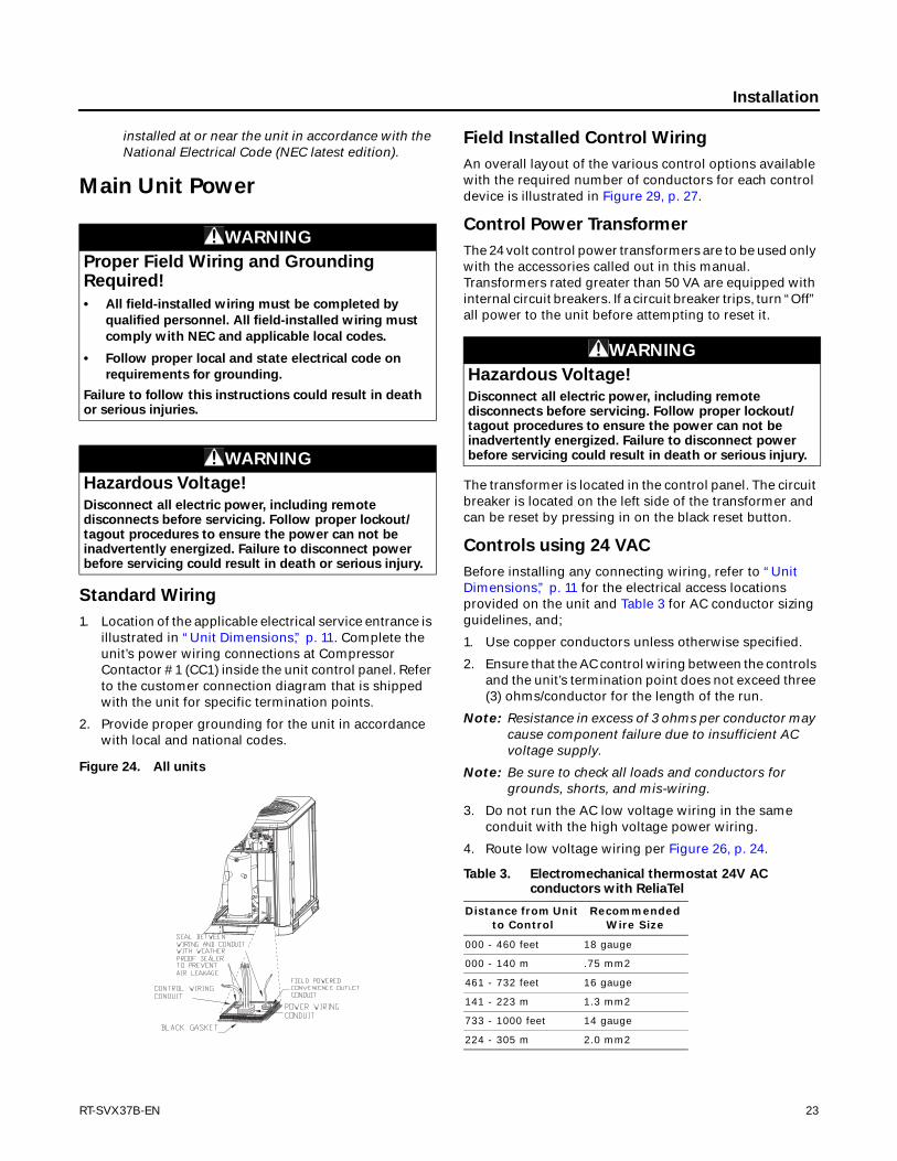
1. Location of the applicable electrical service entrance is illustrated in “Unit Dimensions,” p. 11. Complete the unit’s power wiring connections at Compressor Contactor # 1 (CC1) inside the unit control panel. Refer to the customer connection diagram that is shipped with the unit for specific termination points.
2. Provide proper grounding for the unit in accordance with local and national codes.
Field Installed Control Wiring
An overall layout of the various control options available with the required number of conductors for each control device is illustrated in Figure 29, p. 27.
Control Power Transformer
The 24 volt control power transformers are to be used only with the accessories called out in this manual. Transformers rated greater than 50 VA are equipped with internal circuit breakers. If a circuit breaker trips, turn “Off” all power to the unit before attempting to reset it.
The transformer is located in the control panel. The circuit breaker is located on the left side of the transformer and can be reset by pressing in on the black reset button.
Controls using 24 VAC
Before installing any connecting wiring, refer to “Unit Dimensions,” p. 11 for the electrical access locations provided on the unit and Table 3 for AC conductor sizing guidelines, and;
1. Use copper conductors unless otherwise specified.
2. Ensure that the AC control wiring between the controls and the unit’s termination point does not exceed three (3) ohms/conductor for the length of the run.
Note: Resistance in excess of 3 ohms per conductor may cause component failure due to insufficient AC voltage supply.
Note: Be sure to check all loads and conductors for grounds, shorts, and mis-wiring.
3. Do not run the AC low voltage wiring in the same conduit with the high voltage power wiring.
4. Route low voltage wiring per Figure 26, p. 24.
WARNING
Proper Field Wiring and Grounding Required!
• All field-installed wiring must be completed by
qualified personnel. All field-installed wiring must
comply with NEC and applicable local codes.
• Follow proper local and state electrical code on
requirements for grounding.
Failure to follow this instructions could result in death or serious injuries.
WARNING
Hazardous Voltage!
Disconnect all electric power, including remote disconnects before servicing. Follow proper lockout/tagout procedures to ensure the power can not be inadvertently energized. Failure to disconnect power before servicing could result in death or serious injury.
Figure 24. All units
WARNING
Hazardous Voltage!
Disconnect all electric power, including remote disconnects before servicing. Follow proper lockout/tagout procedures to ensure the power can not be inadvertently energized. Failure to disconnect power before servicing could result in death or serious injury.
Table 3. Electromechanical thermostat 24V AC conductors with ReliaTel
Distance from Unit to Control
Recommended Wire Size
000 - 460 feet 18 gauge
000 - 140 m .75 mm2
461 - 732 feet 16 gauge
141 - 223 m 1.3 mm2
733 - 1000 feet 14 gauge
224 - 305 m 2.0 mm2
RT-SVX37B-EN 23

Installation
Controls using DC Analog Input/Outputs (Standard Low Voltage Multi conductor Wire)
Before installing any connecting wiring between the unit and components utilizing a DC analog input\output signal, refer to “Unit Dimensions,” p. 11 for the electrical access locations provided on the unit.
• Table 4 lists the conductor sizing guidelines that must be followed when interconnecting the DC binary output devices and the system components utilizing a DC analog input\output signal to the unit.
Note: Resistance in excess of 2.5 ohms per conductor can cause deviations in the accuracy of the controls.
Note: Ensure that the wiring between controls and the unit’s termination point does not exceed two and a half (2.5) ohms/conductor for the length of the run.
• Do not run the electrical wires transporting DC signals in or around conduit housing high voltage wires.
• Route low voltage wiring per Figure 26, p. 24.
Space Temperature Averaging
Space temperature averaging is accomplished by wiring a number of remote sensors in a series/parallel circuit.
Using the BAYSENS016* or BAYSENS077*, at least four sensors are required to accomplish space temperature averaging.
Example #1 in Figure 28, p. 26 illustrates two series circuits with two sensors in each circuit wired in parallel. The square of any number of remote sensors is required.
Example #2 Figure 28, p. 26 illustrates three sensors squared in a series/parallel circuit. Using BAYSENS077*, two sensors are required to accomplish space temperature averaging.
Table 4. Zone Sensor Module wiring
Distance from Unit to Control
Recommended Wire Size
0 - 150 feet 22 gauge
0 - 45.7 m .33 mm2
151 - 240 feet 20 gauge
46 - 73.1 m .50 mm2
241 -385 feet 18 gauge
73.5 - 117.3 m .75 mm2
386 - 610 feet 16 gauge
117.7 - 185.9 m 1.3 mm2
611 - 970 feet 14 gauge
186.2 - 295.7 m 2.0 mm2
Figure 25. ReliaTel conventional thermostat field wiring
diagrams
RTRM
Figure 26. ReliaTel control customer low voltage
routing
Figure 27. ReliaTel options module
24 RT-SVX37B-EN

Installation
Example #3 Figure 28, p. 26 illustrates the circuit required for this sensor.
Table 5 lists the temperature versus resistance coefficient for all sensors.
Table 5. Temperature vs resistance
Temperature
Nominal Resistance
Degrees F°
Degrees C°
-20° -28.9° 170.1 K - Ohms
-15° -26.1° 143.5 K - Ohms
-10° -23.3° 121.4 K - Ohms
-5° -20.6° 103.0 K - Ohms
0° -17.8° 87.56 K - Ohms
5° -15.0° 74.65 K - Ohms
10° -12.2° 63.80 K - Ohms
15° -9.4° 54.66 K - Ohms
20° -6.7° 46.94 K - Ohms
25° -3.8° 40.40 K - Ohms
30° -1.1° 34.85 K - Ohms
35° 1.7° 30.18 K - Ohms
40° 4.4° 26.22 K - Ohms
45° 7.2° 22.85 K - Ohms
50° 10.0° 19.96 K - Ohms
55° 12.8° 17.47 K - Ohms
60° 15.6° 15.33 K - Ohms
65° 18.3° 13.49 K - Ohms
70° 21.1° 11.89 K - Ohms
75° 23.9° 10.50 K - Ohms
80° 26.7° 9.297 K - Ohms
85° 29.4° 8.247 K - Ohms
90° 32.2° 7.330 K - Ohms
95° 35.0° 6.528 K - Ohms
RT-SVX37B-EN 25

Installation
Figure 28. Examples
26 RT-SVX37B-EN

Installation
Figure 29. Typical field wiring diagrams for optional controls (ReliaTel only)
BAYSENS106*Zone Sensor
BAYSENS077*ASYSTAT111*
BAYSENS108*Zone Sensor
BAYSENS077*ASYSTAT111*
BAYSENS110*Zone Sensor
BAYSENS073*Zone Sensor
BAYSENS074*Zone Sensor
BAYSENS119*ASYSTAT777*Zone Sensor
BAYSENS077*/ASYSTAT111*
RT-SVX37B-EN 27
Pre-Start
Use the checklist provided below in conjunction with the “General Unit Requirements” checklist to ensure that the unit is properly installed and ready for operation.
• Check all electrical connections for tightness and “point of termination” accuracy.
• Verify that the condenser airflow will be unobstructed.
• Verify that the condenser fan and indoor blower turn freely without rubbing and are properly tightened on the shafts.
• Check the supply fan belts for proper tension and the fan bearings for sufficient lubrication. If the belts require adjustment, or if the bearings need lubricating, refer to the maintenance section of this manual for instructions.
• Verify that a condensate trap is installed and the piping is properly sized and pitched.
• Verify that the correct size and number of filters are in place.
• Inspect the interior of the unit for tools and debris and install all panels in preparation for starting the unit.
Voltage Imbalance
Three phase electrical power to the unit must meet stringent requirements for the unit to operate properly.
Measure each leg (phase-to-phase) of the power supply. Each reading must fall within the utilization range stamped on the unit nameplate. If any of the readings do not fall within the proper tolerances, notify the power company to correct this situation before operating the unit.
Excessive three phase voltage imbalance between phases will cause motors to overheat and eventually fail. The maximum allowable voltage imbalance is 2%. Measure and record the voltage between phases 1, 2, and 3 and calculate the amount of imbalance as follows:
% Voltage Imbalance =
100 X AV - VD where;
AV
AV (Average Voltage) =
Volt 1 + Volt 2 + Volt 3
3
V1, V2, V3 = Line Voltage Readings
VD = Line Voltage reading that deviates the farthest from the average voltage.
• Example: If the voltage readings of the supply power measured 221, 230, and 227, the average volts would be:
221 + 230 + 227 = 226 Avg.
3
VD (reading farthest from average) = 221
The percentage of Imbalance equals:
100 X 226 - 221 = 2.2%
226
The 2.2% imbalance in this example exceeds the maximum allowable imbalance of 2.0%. This much imbalance between phases can equal as much as a 20% current imbalance with a resulting increase in motor winding temperatures that will decrease motor life. If the voltage imbalance is over 2%, notify the proper agencies to correct the voltage problem before operating this equipment.
Electrical Phasing (Three Phase
Motors)
The compressor motor(s) and the supply fan motor are internally connected for the proper rotation when the incoming power supply is phased as A, B, C.
Proper electrical supply phasing can be quickly determined and corrected before starting the unit by using an instrument such as an Associated Research Model 45 Phase Sequence Indicator and following the steps below:
• Turn the field supplied disconnect switch that provides power to the main power terminal block or to the “Line” side of the optional factory mounted disconnect switch to the “Off” position.
• Connect the phase sequence indicator leads to the terminal block or to the “Line” side of the optional factory mounted disconnect switch as follows;
Black (phase A) to L1
Red (phase B) to L2
Yellow (phase C) to L3
• Close the field supplied main power disconnect switch or circuit protector switch that provides the supply power to the unit
WARNING
Hazardous Voltage w/Capacitors!
Disconnect all electric power, including remote disconnects and discharge all motor start/run capacitors before servicing. Follow proper lockout/tagout procedures to ensure the power cannot be inadvertently energized. Verify with an appropriate voltmeter that all capacitors have discharged. Failure to disconnect power and discharge capacitors before servicing could result in death or serious injury.
28 RT-SVX37B-EN

Pre-Start
To prevent injury or death from electrocution, it is the responsibility of the technician to recognize this hazard and use extreme care when performing service procedures with the electrical power energized.
• Observe the ABC and CBA phase indicator lights on the face of the sequencer. The ABC indicator light will glow if the phase is ABC. If the CBA indicator light glows, open the disconnect switch or circuit protection switch and reverse any two power wires.
• Restore the main electrical power and recheck the phasing. If the phasing is correct, open the disconnect switch or circuit protection switch and remove the phase sequence indicator.
Compressor Crankcase Heaters (Standard with all units)
Each compressor is equipped with a crankcase heater. The proper operation of the crankcase heater is important to maintain an elevated compressor oil temperature during the “Off” cycle to reduce oil foaming during compressor starts.
Oil foaming occurs when refrigerant condenses in the compressor and mixes with the oil. In lower ambient conditions, refrigerant migration to the compressor could increase.
When the compressor starts, the sudden reduction in crankcase pressure causes the liquid refrigerant to boil rapidly causing the oil to foam. This condition could damage compressor bearings due to reduced lubrication and could cause compressor mechanical failures.
Before starting the unit in the “Cooling” mode, set the system switch to the “Off” position and turn the main power disconnect to the “On” position and allow the crankcase heater to operate a minimum of 8 hours.
Before closing the main power disconnect switch, insure that the “System” selection switch is in the “Off” position and the “Fan” selection switch is in the “Auto” position.
Close the main power disconnect switch and the unit mounted disconnect switch, if applicable.
To prevent injury or death from electrocution, it is the responsibility of the technician to recognize this hazard and use extreme care when performing service procedures with the electrical power energized.
ReliaTel™ Controls
Upon power initialization, the RTRM performs self-diagnostic checks to insure that all internal controls are functional. It also checks the configuration parameters against the components connected to the system. The Liteport LED located on the RTRM module is turned “On” within one second of power-up if internal operation is okay.
Use one of the following “Test” procedure to bypass some time delays and to start the unit at the control panel. Each step of unit operation can be activated individually by temporarily shorting across the “Test” terminals for two to three seconds. The Liteport LED located on the RTRM module will blink when the test mode has been initiated. The unit can be left in any “Test” step for up to one hour before it will automatically terminate, or it can be terminated by opening the main power disconnect switch. Once the test mode has been terminated, the Liteport LED will glow continuously and the unit will revert to the “System” control.
WARNING
Live Electrical Components!
During installation, testing, servicing and troubleshooting of this product, it may be necessary to work with live electrical components. Have a qualified licensed electrician or other individual who has been properly trained in handling live electrical components perform these tasks. Failure to follow all electrical safety precautions when exposed to live electrical components could result in death or serious injury.
RT-SVX37B-EN 29
Pre-Start
Notes:
1. The condenser fans will operate any time a compressor is On, providing the outdoor air temperatures are within the operating values.
2. The exhaust fan will turn on anytime the economizer damper position is equal to or greater than the exhaust fan setpoint.
3. Steps for optional accessories and non-applicable modes in unit will be skipped.
Test Modes
There are three methods in which the “Test” mode can be cycled at LTB-Test 1 and LTB-Test 2.
1. Step Test Mode - This method initiates the different components of the unit, one at a time, by temporarily shorting across the two test terminals for two to three seconds.
For the initial start-up of the unit, this method allows the technician to cycle a component “On” and have up to one hour to complete the check.
2. Resistance Test Mode - This method can be used for start-up providing a decade box for variable resistance outputs is available. This method initiates the different components of the unit, one at a time, when a specific resistance value is placed across the two test terminals. The unit will remain in the specific test mode for approximately one hour even though the resistance is left on the test terminals.
3. Auto Test Mode - This method is not recommended for start-up due to the short timing between individual component steps. This method initiates the different components of the unit, one at a time, when a jumper is installed across the test terminals. The unit will start the first test step and change to the next step every 30 seconds.
At the end of the test mode, control of the unit will automatically revert to the applied “System” control method.
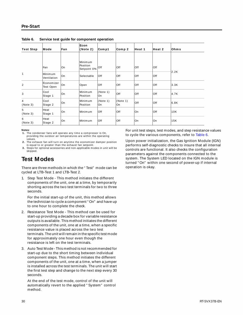
For unit test steps, test modes, and step resistance values to cycle the various components, refer to Table 6.
Upon power initialization, the Gas Ignition Module (IGN) performs self-diagnostic checks to insure that all internal controls are functional. It also checks the configuration parameters against the components connected to the system. The System LED located on the IGN module is turned “On” within one second of power-up if internal operation is okay.
Table 6. Service test guide for component operation
Test Step Mode FanEcon (Note 2) Comp1 Comp 2 Heat 1 Heat 2 Ohms
1
Fan On
Minimum Position Setpoint 0% Off Off Off Off
2.2KMinimumVentilation
On Selectable Off Off Off Off
2EconomizerTest Open
On Open Off Off Off Off 3.3K
3CoolStage 1
OnMinimumPosition
(Note 1)On
Off Off Off 4.7K
4(Note 3)
CoolStage 2
OnMinimumPosition
(Note 1)On
(Note 1)On
Off Off 6.8K
5(Note 3)
HeatStage 1
On Minimum Off Off On Off 10K
6(Note 3)
HeatStage 2
On Minimum Off Off On On 15K
30 RT-SVX37B-EN
Start-Up
Verifying Proper Air Flow
Units with Belt Drive Indoor Fan
Much of the systems performance and reliability is closely associated with, and dependent upon having the proper airflow supplied both to the space that is being conditioned and across the evaporator coil.
The indoor fan speed is changed by opening or closing the adjustable motor sheave.
Before starting the SERVICE TEST, set the minimum position setpoint for the economizer to 0 percent using the setpoint potentiometer located on the Economizer Control (ECA), if applicable.
ReliaTel Control: Using the Service Test Guide in Table 6, p. 30, momentarily jump across the Test 1 & Test 2 terminals on LTB1 one time to start the Minimum Ventilation Test.
Once the supply fan has started, check for proper rotation. The direction of rotation is indicated by an arrow on the fan housing.
With the fan operating properly, determine the total system airflow (CFM) by:
1. Measuring the actual RPM,
2. Measure the amperage at the supply fan contactor and compare it with the full load amp (FLA) rating stamped on the motor nameplate.
a. Calculate the theoretical BHP using (Actual Motor Amps/ Motor Nameplate Amps) X Motor HP.
b. Using the fan performance tables in the unit Service Facts, plot the actual RPM (step 1) and the BHP (step 2a) to obtain the operating CFM.
3. If the required CFM is too low, (external static pressure is high causing motor HP output to be below table value),
a. Relieve supply and/or return duct static.
b. Change indoor fan speed and repeat Step 1 and Step 2.
• To Increase Fan RPM; Loosen the pulley adjustment set screw and turn sheave clockwise.
• To Decrease Fan RPM; Loosen the pulley adjustment set screw and turn sheave counterclockwise.
• If the required CFM is too high, (external static pressure is low causing motor HP output to be above table value), change indoor fan speed and repeat Step 1 and Step 2.
• To stop the SERVICE TEST, turn the main power disconnect switch to the "Off" position or proceed to the next component start-up procedure.
Economizer Start-Up
ReliaTel Control: Using the Service Test Guide in Table 6, p. 30, momentarily jump across the Test 1 & Test 2 terminals on LTB1 one time to start the Minimum Ventilation Test below.
1. Set the minimum position setpoint for the economizer to the required percentage of minimum ventilation using the setpoint potentiometer located on the Economizer Control (ECA).
The economizer will drive to its minimum position setpoint, exhaust fans (if applicable) may start at random, and the supply fan will start when the SERVICE TEST is initiated.
The Exhaust Fan will start anytime the economizer damper position is equal to or greater than the exhaust fan setpoint.
2. Verify that the dampers stroked to the minimum position.
WARNING
Live Electrical Components!
During installation, testing, servicing and troubleshooting of this product, it may be necessary to work with live electrical components. Have a qualified licensed electrician or other individual who has been properly trained in handling live electrical components perform these tasks. Failure to follow all electrical safety precautions when exposed to live electrical components could result in death or serious injury.
WARNING
Rotating Components!
During installation, testing, servicing and troubleshooting of this product it may be necessary to measure the speed of rotating components. Have a qualified or licensed service individual who has been properly trained in handling exposed rotating components, perform these tasks. Failure to follow all safety precautions when exposed to rotating components could result in death or serious injury.
RT-SVX37B-EN 31
Start-Up
ReliaTel Control
Momentarily jump across the Test 1 & Test 2 terminals on LTB1 one additional time if continuing from previous component start-up or until the desired start-up component Test is started.
3. Verify that the dampers stroked to the full open position.
4. To stop the SERVICE TEST, turn the main power disconnect switch to the “Off” position or proceed to the next component start-up procedure. Remove electro mechanical test mode connections (if applicable).
Compressor Start-Up
1. Attach a set of service gauges onto the suction and discharge gauge ports for each circuit. Refer to the refrigerant circuit illustration in the Service Facts.
ReliaTel Control
Momentarily jump across the Test 1 & Test 2 terminals on LTB1 one additional time if continuing from previous component start-up or until the desired start-up component Test is started.
Scroll Compressors
a. Once each compressor has started, verify that the rotation is correct. If a scroll compressor is rotating backwards, it will not pump and a loud rattling sound can be observed.
b. If the electrical phasing is correct, before condemning a compressor, interchange any two leads (at the compressor Terminal block) to check the internal phasing. If the compressor runs backward for an extended period (15 to 30 minutes), the motor winding can overheat and cause the motor winding thermostat to open.
2. After the compressor and condenser fan have started and operated for approximately 30 minutes, observe the operating pressures. Compare the operating pressures to the operating pressure curve in the Service Facts.
3. Check system superheat. Follow the instruction listed on the superheat charging curve in the Service Facts.
4. Superheat should be within ±5 F of the superheat chart value.
5. Repeat Step 1 through Step 4 for each refrigerant circuit.
6. To stop the SERVICE TEST, turn the main power disconnect switch to the “Off” position or proceed to the next component start-up procedure. Remove electro mechanical test mode connections (if applicable).
Final System Setup
After completing all of the pre-start and start-up procedures outlined in the previous sections (i.e., operating the unit in each of its Modes through all available stages of cooling & heating), perform these final checks before leaving the unit:
• Program the Night Setback (NSB) panel (if applicable) for proper unoccupied operation. Refer to the programming instructions for the specific panel.
• Verify that the Remote panel “System” selection switch, “Fan” selection switch, and “Zone Temperature” settings for automatic operation are correct.
• Inspect the unit for misplaced tools, hardware, and debris.
• Verify that all exterior panels including the control panel doors and condenser grilles are secured in place.
• Close the main disconnect switch or circuit protector switch that provides the supply power to the unit’s terminal block or the unit mounted disconnect switch.
Make sure all personnel are standing clear of the unit before proceeding. The system components will start when the power is applied.
WARNING
Live Electrical Components!
During installation, testing, servicing and troubleshooting of this product, it may be necessary to work with live electrical components. Have a qualified licensed electrician or other individual who has been properly trained in handling live electrical components perform these tasks. Failure to follow all electrical safety precautions when exposed to live electrical components could result in death or serious injury.
32 RT-SVX37B-EN

Maintenance
Fan Belt Adjustment - Belt Drive
Units
The fan belts must be inspected periodically to assure proper unit operation.
Replacement is necessary if the belts appear frayed or worn. Units with dual belts require a matched set of belts to ensure equal belt length.
When removing or installing the new belts, do not stretch them over the sheaves. Loosen the belts using the belt tension adjustment bolts on the motor mounting base.
Once the new belts are installed, using a Browning or Gates tension gauge (or equivalent) illustrated in Figure 30; adjust the belt tension as follows;
1. To determine the appropriate belt deflection;
a. Measure the center-to-center shaft distance (in inches) between the fan and motor sheaves.
b. Divide the distance measured in Step a by 64; the resulting value represents the amount of belt deflection that corresponds to the proper belt tension.
2. Set the large O-ring on the belt tension gauge at the deflection value determined in Step b.
3. Set the small O-ring at zero on the force scale of the gauge plunger.
4. Place the large end of the gauge at the center of the belt span; then depress the gauge plunger until the large O-ring is even with the top of the next belt or even with a straightedge placed across the fan and motor sheaves. Refer to Figure 9.
5. Remove the belt tension gauge. The small O-ring now indicates a number other than zero on the plunger’s force scale. This number represents the force (in pounds) required to give the needed deflection.
6. Compare the “force” scale reading (Step 5) with the appropriate “force” value listed in Table 7. If the “force” reading is outside the range, readjust the belt tension.
Note: Actual belt deflection “force” must not exceed the maximum “force” value shown in Table 7.
7. Recheck the belt tension at least twice during the first 2 to 3 days of operation. Belt tension may decrease until the new belts are “run in”.
Monthly Maintenance
Before completing the following checks, turn the unit OFF and lock the main power disconnect switch open.
Filters
Inspect the return air filters. Clean or replace them if necessary. Refer to the unit Service Facts for filter information.
Condensate Overflow Switch
During maintenance, the switch float (black ring) must be
WARNING
Rotating Components!
During installation, testing, servicing and troubleshooting of this product it may be necessary to measure the speed of rotating components. Have a qualified or licensed service individual who has been properly trained in handling exposed rotating components, perform these tasks. Failure to follow all safety precautions when exposed to rotating components could result in death or serious injury.
Figure 30. Belt tension gauge
Table 7. Belt Tension Measurement and Deflection
Deflection Force (Lbs.)
Belts Cross Section
Small P.D Range
Super Gripbelts Gripnotch
Steel Cable Gripbelts
Min. Max. Min. Max. Min. Max
3.0 - 3.6 3 4 1/2 3 7/8 5 1/2 3 1/4 4
A 3.8 - 4.8 3 1/2 5 4 1/2 6 1/4 3 3/4 4 3/4
5.0 - 7.0 4 5 1/2 5 6 7/8 4 1/4 5 1/4
3.4 - 4.2 4 5 1/2 5 3/4 8 4 1/2 5 1/2
B 4.4 - 5.6 5 1/8 7 1/8 6 1/2 9 1/8 5 3/4 7 1/4
5.8 - 8.8 6 3/8 8 3/4 7 3/8 10 1/8 7 8 3/4
WARNING
Rotating Components!
During installation, testing, servicing and troubleshooting of this product it may be necessary to measure the speed of rotating components. Have a qualified or licensed service individual who has been properly trained in handling exposed rotating components, perform these tasks. Failure to follow all safety precautions when exposed to rotating components could result in death or serious injury.
RT-SVX37B-EN 33

Maintenance
checked to ensure free movement up and down.
Cooling Season
• Check the unit’s drain pans and condensate piping to ensure that there are no blockages.
• Inspect the evaporator and condenser coils for dirt, bent fins, etc. If the coils appear dirty, clean them according to the instructions described in “Coil Cleaning” later in this section.
• Manually rotate the condenser fan(s) to ensure free movement and check motor bearings for wear. Verify that all of the fan mounting hardware is tight.
• Inspect the F/A-R/A damper hinges and pins to ensure that all moving parts are securely mounted. Keep the blades clean as necessary.
• Verify that all damper linkages move freely; lubricate with white grease, if necessary.
• Check supply fan motor bearings; repair or replace the motor as necessary.
• Check the fan shaft bearings for wear. Replace the bearings as necessary.
• Check the supply fan belt. If the belt is frayed or worn, replace it. Refer to the “Fan Belt Adjustment” section for belt replacement and adjustments.
• Verify that all wire terminal connections are tight.
• Remove any corrosion present on the exterior surfaces of the unit and repaint these areas.
• Generally inspect the unit for unusual conditions (e.g., loose access panels, leaking piping connections, etc.)
• Make sure that all retaining screws are reinstalled in the unit access panels once these checks are complete.
• With the unit running, check and record the: ambient temperature; compressor suction and discharge pressures (each circuit); superheat (each circuit);
• Record this data on an “operator’s maintenance log” like the one shown in Table 8, p. 36. If the operating pressures indicate a refrigerant shortage, measure the system superheat. For guidelines, refer to the “Compressor Start-Up” section.
Note: Do not release refrigerant to the atmosphere! If adding or removing refrigerant is required, the service technician must comply with all federal, state and local laws.
Heating Season
• Inspect the unit’s air filters. If necessary, clean or replace them.
• Check supply fan motor bearings; repair or replace the motor as necessary.
• Inspect both the main unit control panel and heat section control box for loose electrical components and terminal connections, as well as damaged wire insulation. Make any necessary repairs.
• Verify that the electric heat system operates properly.
Coil Cleaning
Regular coil maintenance, including annual cleaning, enhances the unit’s operating efficiency by minimizing: compressor head pressure and amperage draw; evaporator water carryover; fan brake horsepower, due to increase static pressure losses; airflow reduction.
At least once each year, or more often if the unit is located in a “dirty” environment, clean the evaporator and condenser coils using the instructions outlined below. Be sure to follow these instructions as closely as possible to avoid damaging the coils.
Note: For units equipped with hail guards follow removal procedure listed below.
Hail Guard Removal
• Unlatch hail guard.
• Pull the top of the hail guard outward until the fastener studs are free of the retaining nuts.
• Lift the hail guard from the lower retaining bracket and set aside.
To clean refrigerant coils, use a soft brush and a sprayer (either a garden pump-up type or a high-pressure sprayer). A high-quality detergent is also required; suggested brands include “SPREX A.C.”, “OAKITE 161”, “OAKITE 166” and “COILOX”. If the detergent selected is strongly alkaline (ph value exceeds 8.5), add an inhibitor.
1. Remove enough panels from the unit to gain access to the coil.
2. Protect all electrical devices such as motors and controllers from any over spray.
3. Straighten any bent coil fins with a fin comb.
4. Mix the detergent with water according to the manufacturer’s instructions. If desired, heat the solution BUT DO NOT EXCEED 150ºF maximum to improve its cleansing capability.
WARNING
Hazardous Chemicals!
Coil cleaning agents can be either acidic or highly alkaline. Handle chemical carefully. Proper handling should include goggles or face shield, chemical resistant gloves, boots, apron or suit as required. For personal safety refer to the cleaning agent manufacturer’s Materials Safety Data Sheet and follow all recommended safe handling practices. Failure to follow all safety instructions could result in death or serious injury.
34 RT-SVX37B-EN
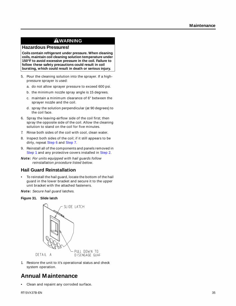
Maintenance
5. Pour the cleaning solution into the sprayer. If a high-pressure sprayer is used:
a. do not allow sprayer pressure to exceed 600 psi.
b. the minimum nozzle spray angle is 15 degrees.
c. maintain a minimum clearance of 6" between the sprayer nozzle and the coil.
d. spray the solution perpendicular (at 90 degrees) to the coil face.
6. Spray the leaving-airflow side of the coil first; then spray the opposite side of the coil. Allow the cleaning solution to stand on the coil for five minutes.
7. Rinse both sides of the coil with cool, clean water.
8. Inspect both sides of the coil; if it still appears to be dirty, repeat Step 6 and Step 7.
9. Reinstall all of the components and panels removed in Step 1 and any protective covers installed in Step 2.
Note: For units equipped with hail guards follow reinstallation procedure listed below.
Hail Guard Reinstallation
• To reinstall the hail guard, locate the bottom of the hail guard in the lower bracket and secure it to the upper unit bracket with the attached fasteners.
Note: Secure hail guard latches.
1. Restore the unit to it’s operational status and check system operation.
Annual Maintenance
• Clean and repaint any corroded surface.
WARNING
Hazardous Pressures!
Coils contain refrigerant under pressure. When cleaning coils, maintain coil cleaning solution temperature under 150°F to avoid excessive pressure in the coil. Failure to follow these safety precautions could result in coil bursting, which could result in death or serious injury.
Figure 31. Slide latch
RT-SVX37B-EN 35

Maintenance
Final Process
For future reference, you may find it helpful to record the unit data requested in the blanks provided.
Complete Model Number
Unit Serial Number
Wiring Diagram Numbers (from unit control panel)
Schematics
Connections
Table 8. Sample maintenance log
Refrigerant Circuit #1 Refrigerant Circuit #2
Date
Current Ambient Temp. F/C
Compr. Oil Level
Suct. Press. Psig/kPa
Disch. Press. Psig/kPa
Liquid Press. Psig/kPa
Super-heat F/C
Sub-cool. F/C
Compr. Oil Level
Suct. Press. Psig/kPa
Disch. Press. Psig/kPa
Liquid Press. Psig/kPa
Super-heat F/C
Sub-cool. F/C
- ok- low
- ok- low
- ok- low
- ok- low
- ok- low
- ok- low
- ok- low
- ok- low
- ok- low
- ok- low
- ok- low
- ok- low
- ok- low
- ok- low
- ok- low
- ok- low
- ok- low
- ok- low
- ok- low
- ok- low
- ok- low
- ok- low
Note: Check and record the data requested above each month during the cooling season with the unit running
36 RT-SVX37B-EN

Trouble Shooting
ReliaTel™ Control
The RTRM has the ability to provide the service personnel with some unit diagnostics and system status information.
Before turning the main power disconnect switch “Off”, follow the steps below to check the ReliaTel Refrigeration Module (RTRM). All diagnostics & system status information stored in the RTRM will be lost when the main power is turned “Off”.
To prevent injury or death from electrocution, it is the responsibility of the technician to recognize this hazard and use extreme care when performing service procedures with the electrical power energized.
1. Verify that the Liteport LED on the RTRM is burning continuously. If the LED is lit, go to Step 3.
2. If the LED is not lit, Verify that 24 VAC is present between J1-1 and J1-2. If 24VAC is present, proceed to Step 3. If 24VAC is not present, check the unit main power supply, transformer (TNS1), and make sure the condensate overflow switch (if equipped) is not open.
3. Utilizing “Method 1” or “Method 2” in the “System Status Diagnostic” section, check the following:
System status
Heating status
Cooling status
If a System failure is indicated, proceed to Step 4. If no failures are indicated, proceed to Step 5.
4. If a System failure is indicated, recheck Step 1 and Step 2. If the LED is not lit in Step 1, and 24 VAC is present in Step 2, the RTRM has failed. Replace the RTRM.
5. If no failures are indicated, use one of the TEST mode procedures described in the “Unit Start-Up” section to start the unit. This procedure will allow you to check all of the RTRM outputs, and all of the external controls (relays, contactors, etc.) that the RTRM outputs energize, for each respective mode. Proceed to Step 6.
6. Step the system through all of the available modes, and verify operation of all outputs, controls, and modes. If a problem in operation is noted in any mode, you may leave the system in that mode for up to one hour while troubleshooting. Refer to the sequence of
operations for each mode, to assist in verifying proper operation. Make the necessary repairs and proceed to Step 7 and Step 8.
7. If no abnormal operating conditions appear in the test mode, exit the test mode by turning the power “Off” at the main power disconnect switch.
8. Refer to the individual component test procedures if other microelectronic components are suspect.
System Status Checkout
Procedure
“System Status” is checked by using one of the following two methods:
Method 1
If the Zone Sensor Module (ZSM) is equipped with a remote panel with LED status indication, you can check the unit within the space. If the ZSM does not have LED’s, use Method 2. BAYSENS110*, BAYSENS109*, BAYSENS119*, BAYSENS023A all have the remote panel indication feature. The LED descriptions are listed below.
LED 1 (System)
“On” during normal operation.
“Off” if a system failure occurs or the LED fails.
“Flashing” indicates test mode.
LED 2 (Heat)
“On” when the heat cycle is operating.
“Off” when the heat cycle terminates or the LED fails.
“Flashing” indicates a heating failure.
LED 3 (Cool)
“On” when the cooling cycle is operating.
“Off” when the cooling cycle terminates or the LED fails.
“Flashing” indicates a cooling failure.
LED 4 (Service)
“On” indicates a clogged filter.
“Off” during normal operation.
“Flashing” indicates an evaporator fan failure
Below is the complete listing of failure indication causes.
System failure
Check the voltage between terminals 6 and 9 on J6, it should read approximately 32 VDC. If no voltage is present, a system failure has occurred. Refer to Step 4 in the previous section for the recommended troubleshooting procedure.
WARNING
Live Electrical Components!
During installation, testing, servicing and troubleshooting of this product, it may be necessary to work with live electrical components. Have a qualified licensed electrician or other individual who has been properly trained in handling live electrical components perform these tasks. Failure to follow all electrical safety precautions when exposed to live electrical components could result in death or serious injury.
RT-SVX37B-EN 37

Trouble Shooting
Cooling Failure
1. Cooling and heating set point (slide pot) on the zone sensor has failed. Refer to the “Zone Sensor Test Procedure” section.
2. Zone temperature thermistor ZTEMP on ZTS failed. Refer to the “Zone Sensor Test Procedure” section.
3. CC1 or CC2 24 VAC control circuit has opened, check CC1 & CC2 coils, and any of the controls below that apply to the unit (HPC1, HPC2).
4. LPC1 has opened during the 3 minute minimum “on time” during 4 consecutive compressor starts, check LPC1 or LPC2 by testing voltage between the J1-1 & J3-2 terminals on the RTRM and ground. If 24 VAC is present, the LPC’s has not tripped. If no voltage is present, LPC’s has tripped.
Service Failure
1. If the supply fan proving switch has closed, the unit will not operate (when connected to RTOM), check the fan motor, belts, and proving switch.
2. Clogged filter switch has closed, check the filters.
3. If the condensate overflow switch is closed, the unit will not operate, check the float position is not in a tripped condition and verify an “open” between wires connecting to RTOM J6-1, J6-2.
Simultaneous Heat and Cool Failure
1. Emergency Stop is activated
Method 2
The second method for determining system status is done by checking voltage readings at the RTRM (J6). The system indication descriptions and the approximate voltages are listed below.
System Failure
Measure the voltage between terminals J6-9 & J6-6.
Normal Operation = approximately 32 VDC
System Failure = less than 1 VDC, approximately 0.75 VDC
Test Mode = voltage alternates between 32 VDC & 0.75 VDC
Heat Failure
Measure the voltage between terminals J6-7 & J6-6.
Heat Operating = approximately 32 VDC
Heat Off = less than 1 VDC, approximately 0.75 VDC
Heating Failure = voltage alternates between 32 VDC & 0.75 VDC
Cool Failure
Measure the voltage between terminals J6-8 & J6-6.
Cool Operating = approximately 32 VDC
Cool Off = less than 1 VDC, approximately 0.75 VDC
Cooling Failure = voltage alternates between 32 VDC & 0.75 VDC
Service Failure
Measure the voltage between terminals J6-10 & J6-6.
Clogged Filter = Approximately 32 VDC.
Normal = Less than 1 VDC, approximately 0.75 VDC Fan Failure = voltage alternates between 32 VDC & 0.75 VDC.
To use LED’s for quick status information at the unit, purchase a BAYSENS110* ZSM and connect wires with alligator clamps to terminals 6 through 10. Connected each respective terminal wire (6 through 10) from the Zone Sensor to the unit J6 terminals 6 through 10.
Note: If the system is equipped with a programmable zone sensor, (BAYSENS119*, or BAYSENS023A), the LED indicators will not function while the BAYSENS110* is connected.
Resetting Cooling and Ignition Lockouts
Cooling Failures and Heating Lockouts are reset in an identical manner. Method 1 explains resetting the system from the space; Method 2 explains resetting the system at the unit.
Note: Before resetting Cooling Failures and Ignition Lockouts check the Failure Status Diagnostics by the methods previously explained. Diagnostics will be lost when the power to the unit is disconnected.
Method 1
To reset the system from the space, turn the “Mode” selection switch at the zone sensor to the “Off” position. After approximately 30 seconds, turn the “Mode” selection switch to the desired mode, i.e. Heat, Cool or Auto.
Method 2
To reset the system at the unit, cycle the unit power by turning the disconnect switch “Off” and then “On”.
Lockouts can be cleared through the building management system. Refer to the building management system instructions for more information.
Zone Temperature Sensor (ZTS)
Service Indicator
The ZSM SERVICE LED is a generic indicator, that will signal the closing of a Normally Open switch at any time, providing the Indoor Motor (IDM) is operating. This indicator is usually used to indicate a clogged filter, or an air side fan failure.
The RTRM will ignore the closing of this Normally Open switch for 2 (±1) minutes. This helps prevent nuisance SERVICE LED indications. The exception is the LED will flash 40 seconds after the fan is turned “On” if the Fan Proving Switch is not made.
38 RT-SVX37B-EN

Trouble Shooting
Clogged Filter Switch
This LED will remain lit the entire time that the Normally Open switch is closed. The LED will be turned off immediately after resetting the switch (to the Normally Open position), or any time that the IDM is turned “Off”.
If the switch remains closed, and the IDM is turned “On”, the SERVICE LED will be turned “On” again after the 2 (±1) minute ignore delay.
This LED being turned “On”, will have no other affect on unit operation. It is an indicator only.
Fan Failure Switch
When the “Fan Failure” switch is wired to the RTOM, the LED will remain flashing the entire time the fan proving switch is closed, indicating a fan failure, and it will shut the unit operations down.
Condensate Overflow Switch
When the “Condensate Overflow Switch” is closed, a drain pan overflow condition is indicated and it will shut unit operations down.
Zone Temperature Sensor (ZTS)
Test
Note: These procedures are not for programmable or digital models and are conducted with the Zone Sensor Module electrically removed from the system.
Test 1 - Zone Temperature Thermistor (ZTEMP)
This component is tested by measuring the resistance between terminals 1 and 2 on the Zone Temperature Sensor. Below are some typical indoor temperatures, and corresponding resistive values.
Test 2 - Cooling Set Point (CSP) and Heating Set Point (HSP)
The resistance of these potentiometers are measured between the following ZSM terminals. Refer to the chart above for approximate resistances at the given setpoints.
Cool SP = Terminals 2 and 3
Range = 100 to 900 Ohms approximate
Heat SP = Terminals 2 and 5
Range = 100 to 900 Ohms approximate
Test 3 - System Mode and Fan Selection
The combined resistance of the Mode selection switch and the Fan selection switch can be measured between terminals 2 and 4 on the Zone Sensor. The possible switch combinations are listed below with their corresponding resistance values.
Test 4 - LED Indicator Test, (SYS ON, HEAT, COOL & SERVICE)
Method 1
Testing the LED using a meter with diode test function. Test both forward and reverse bias. Forward bias should measure a voltage drop of 1.5 to 2.5 volts, depending on your meter. Reverse bias will show an Over Load, or open circuit indication if LED is functional.
Method 2
Testing the LED with an analog Ohmmeter. Connect Ohmmeter across LED in one direction, then reverse the leads for the opposite direction. The LED should have at least 100 times more resistance in reverse direction, as compared with the forward direction. If high resistance in both directions, LED is open. If low in both directions, LED is shorted.
Method 3
To test LED’s with ZSM connected to unit, test voltages at LED terminals on ZSM. A measurement of 32 VDC, across an unlit LED, means the LED has failed.
Programmable & Digital Zone Sensor Test
Testing serial communication voltage
1. Verify 24 VAC is present between terminals J6-14 & J6-11.
2. Disconnect wires from J6-11 and J6-12. Measure the voltage between J6-11 and J6-12, should be about 32 VDC.
3. Reconnect wires to terminals J6-11 and J6-12. Measure voltage again between J6-11 and J6-12, voltage should flash high and low every 0.5 seconds. The voltage on the low end will measure about 19 VDC, while the voltage on the high end will measure from approximately 24 to 38 VDC.
4. Verify all modes of operation, by running the unit through all of the steps in the “Test Modes” section discussed in “Unit Start-Up”.
Table 9. Cooling setpoint and heating setpoint
Zone TemperatureNominal ZTEMP
Resistance
50 F° 10.0 C° 19.9 K-Ohms
55 F° 12.8 C° 17.47 K-Ohms
60 F° 15.6 C° 15.3 K-Ohms
65 F° 18.3 C° 13.49 K-Ohms
70 F° 21.1 C° 11.9 K-Ohms
75 F° 23.9 C° 10.50 K-Ohms
80 F° 26.7 C° 9.3 K-Ohms
85 F° 29.4 C° 8.25 K-Ohms
90 F° 32.2 C° 7.3 K-Ohms
RT-SVX37B-EN 39

Trouble Shooting
5. After verifying proper unit operation, exit the test mode. Turn the fan on continuously at the ZSM, by pressing the button with the fan symbol. If the fan comes on and runs continuously, the ZSM is good. If you are not able to turn the fan on, the ZSM is defective.
ReliaTel Refrigeration Module (RTRM) Default Chart
If the RTCI loses input from the building management system, the RTRM will control in the default mode after approximately 15 minutes. If the RTRM loses the Heating and Cooling setpoint input, the RTRM will control in the default mode instantaneously. The temperature sensing thermistor in the Zone Sensor Module is the only component required for the “Default Mode” to operate.
Unit Operation without a Zone Sensor
This procedure is for temporary operation only. The economizer and condenser fan cycling functions are disabled.
1. Open and Lock the unit disconnect switch.
2. Remove the Outside Air Sensor (OAS) from the condenser section of unit.
3. Use two (2) wire nuts, to individually cap the wires.
4. Locate the RTRM (J6). Connect two (2) wires to terminals J6-1 and 2.
5. Connect the sensor (OAS) using two wire nuts to the two (2) field supplied wires that were connected to terminals 1 and 2 on J6.
Unit Economizer Control (ECA)
Troubleshooting
ReliaTel Control
Verify Economizer Status by Economizer Actuator (ECA) LED indicator:
OFF: No Power or Failure
ON: Normal, OK to Economize
Slow Flash: Normal, Not OK to Economize
Fast Flash - 1/2 Second On / 2 Seconds Off:
Error Code:
Communications Failure
Pulse Flash: 2 Seconds On / 1/2 Second Off:
Error Code:
1. Flash: Actuator Fault
2. Flashes: CO2 Sensor
3. Flashes: RA Humidity Sensor
4. Flashes: RA Temp Sensor
5. Flashes: OA Quality Sensor
6. Flashes: OA Humidity Sensor
7. Flashes: OA Temp Sensor
8. Flashes: MA Temp Sensor
9. Flashes: RAM Fault
10. Flashes: ROM Fault
11. Flashes:EEPROM Fault
40 RT-SVX37B-EN

Wiring Diagrams
Cooling Capacity
Connection Diagram Power Diagram Control Diagram
060E 4366-1509-0104 4366-1020-0104 4366-1026-0104
072E 4366-1541-0110 4366-1020-0104 4366-1026-0104
090E 4366-1541-0110 4366-1020-0104 4366-1026-0104
102E 4366-1534-0110 4366-1037-0110 4366-1044-0110
120E 4366-1534-0110 4366-1037-0110 4366-1044-0110
RT-SVX37B-EN 41


The manufacturer optimizes the performance of homes and buildings around the world. A business of Ingersoll Rand, the leader in creating and sustaining safe, comfortable and energy efficient environments,the manufacturer offers a broad portfolio of advanced controls and HVAC systems, comprehensive building services, and parts. For more information, visit www.IRCO.com.
The manufacturer has a policy of continuous product and product data improvement and reserves the right to change design and specifications without notice.
We are committed to using environmentally
conscious print practices that reduce waste.
© 2012 Trane All rights reserved
RT-SVX37B-EN 10 Sep 2012
Supersedes RT-SVX37A-EN (Nov 2009)