INSTALLATION & OPERATING INSTRUCTIONS …A).pdfECONOMIZERS WITH EXHAUST for EQUIPMENT BUILDING...
25
Page 1 of 25 ECONOMIZERS WITH EXHAUST for EQUIPMENT BUILDING APPLICATIONS Models ECONWMT-T2B* & ECONWMT-T3B* (Factory Installed Vent Option “T”) with D.B. OUTDOOR CONTROL & ECONWMT-E2B* & ECONWMT-E3B* (Factory Installed Vent Option “W”) with ENTHALPY OUTDOOR CONTROL For Use with 1-1/2 through 3 Ton Wall Mount Air Conditioners and Heat Pumps INSTALLATION & OPERATING INSTRUCTIONS Manual: 2100-575A Supersedes: 2100-575 File: Volume III Tab 19 Date: 04-17-13 NOTE: These instructions are written to cover field-installed economizers, but are also included with factory installed economizers. For factory installed economizers, all portions addressing “installation” are for reference only. BMC, Inc. Bryan, Ohio 43506
Transcript of INSTALLATION & OPERATING INSTRUCTIONS …A).pdfECONOMIZERS WITH EXHAUST for EQUIPMENT BUILDING...

Manual 2100-575A
Page 1 of 25
ECONOMIZERS WITH EXHAUST
for EQUIPMENT BUILDING APPLICATIONS
Models
ECONWMT-T2B* & ECONWMT-T3B*
(Factory Installed Vent Option “T”)
with D.B. OUTDOOR CONTROL
&
ECONWMT-E2B* & ECONWMT-E3B*
(Factory Installed Vent Option “W”)
with ENTHALPY OUTDOOR CONTROL
For Use with 1-1/2 through 3 Ton
Wall Mount Air Conditioners
and Heat Pumps
INSTALLATION & OPERATING
INSTRUCTIONS
Manual: 2100-575A
Supersedes: 2100-575
File: Volume III Tab 19
Date: 04-17-13
NOTE: These instructions are written to cover field-installed economizers, but
are also included with factory installed economizers. For factory
installed economizers, all portions addressing “installation” are for
reference only.
BMC, Inc.
Bryan, Ohio 43506

Manual 2100-575A
Page 2 of 25
CONTENTS
GENERAL
Nomenclature .......................................................... 3General Information ................................................. 3Unpacking ................................................................ 3Description ............................................................... 3
INSTALLATION
Basic Installation ............................................. 4-5 & 7Control Wiring Connection ...................................... 8Intake Air Hood Assembly ...................................... 14Left-Hand Applications Only .................................. 14JADE™ Economizer Controller ............................. 16Start-Up / Checkout Procedures ............. 17 - 19 & 21Enthalpy Settings ................................................... 20Economizer Sequence of Operation Condition - Cool Outdoor Ambient Conditions .... 22 Condition - Warm Outdoor Ambient Conditions .. 22Economizer Features............................................. 23Economizer Operation for Single Stage................. 24Economizer Operation for Two Stage .................... 25
FIGURES
Figure 1 HVAC Unit Access Panels ...................... 4
Figure 2 Left & Right Filter Brackets ..................... 5
Figure 3 Condenser Exh. Plate w/Screen ............. 6
Figure 4 Mixed Air Sensor Location ...................... 7
Figure 5 Mixed Air Sensor Location ...................... 7
Figure 6 24V Control Wiring w/1-Stage A/C .......... 9
Figure 7 24V Control Wiring w/2-Stage A/C ........ 10
Figure 8 24V Control Wiring w/1-Stage HP ..........11
Figure 9 24V Control Wiring w/2-Stage HP ......... 12
Figure 10 2-Stage HP w/Dehum. & Opt. Elec. Heat .. 13
Figure 11 Economizer Hood Install Steps ............. 15
Figure 12 Left Hand Economizer .......................... 16
Figure Enthalpy ................................................ 20
Figure 13 100% Outside Airflow Path ................... 22
Figure 14 Mixed Airflow Path ................................ 22
Figure 15 100% Closed Loop Airflow Path ........... 23
TABLES
Table 1 Economizer Application........................... 3
Table 2 System Setup ........................................ 17
Table 3 Advanced Setup ................................... 18
Table 4 Setpoints ............................................... 18
Table 5 Checkout ............................................... 19
Table 6 Status .................................................... 19
Table Enthalpy ................................................ 20
Table 7 Alarms ................................................... 21
Manual 2100-575APage 3 of 25
GENERAL
GENERAL INFORMATION
The economizer should only be installed by a trained
heating and air conditioning technician. These instructions
serve as a guide to the technician installing an economizer
package, not as a step-by-step procedure with which the
mechanically inclined owner can install the package.
The economizer housing is shipped in one carton, which
contains the electrical harness, miscellaneous hardware
and installation instructions.
The economizer installation requires the use of a 2-stage
cooling thermostat (if there is not one already present)
and requisite amounts of low voltage conductor wire for
two-stage cooling. The number of low-voltage control
conductors will vary depending upon application.
If using a master controller, the MC4000 controller is
designed specifically to control two (2) redundant wall
mount units equipped with economizers.
Any wall mount unit equipped with an economizer must also
have a factory/field installed low ambient control. Please
refer to appropriate model/year Specification Sheet for
requisite field installed low ambient control kit part numbers.
UNPACKING
Upon receipt of the equipment, be sure to compare the
model number found on the shipping label with the
accessory identification information on the orders and
shipping document to verify that the correct accessory
has been shipped.
Inspect the carton housing of each economizer assembly
as it is received, and before signing the freight bill –
verify that all items have been received and there is no
visible damage. Note any shortages or damage on all
copies of the freight bill. The receiving party must
contact the last carrier immediately, preferably in writing,
requesting inspection by the carrier’s agent. Concealed
damage not discovered until after loading must be
reported to the carrier within 15 days of its receipt.
NOTE: Factory installed Telcom economizers have
the air intake hood shipped knocked-down.
See “Intake Air Hood Assembly” section for
shipping location of hood parts and follow the
assembly instructions.
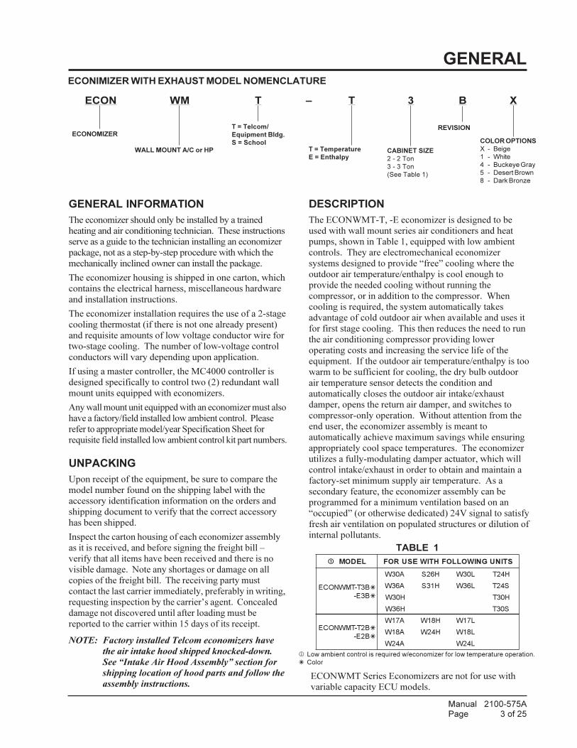
DESCRIPTION
The ECONWMT-T, -E economizer is designed to be
used with wall mount series air conditioners and heat
pumps, shown in Table 1, equipped with low ambient
controls. They are electromechanical economizer
systems designed to provide “free” cooling where the
outdoor air temperature/enthalpy is cool enough to
provide the needed cooling without running the
compressor, or in addition to the compressor. When
cooling is required, the system automatically takes
advantage of cold outdoor air when available and uses it
for first stage cooling. This then reduces the need to run
the air conditioning compressor providing lower
operating costs and increasing the service life of the
equipment. If the outdoor air temperature/enthalpy is too
warm to be sufficient for cooling, the dry bulb outdoor
air temperature sensor detects the condition and
automatically closes the outdoor air intake/exhaust
damper, opens the return air damper, and switches to
compressor-only operation. Without attention from the
end user, the economizer assembly is meant to
automatically achieve maximum savings while ensuring
appropriately cool space temperatures. The economizer
utilizes a fully-modulating damper actuator, which will
control intake/exhaust in order to obtain and maintain a
factory-set minimum supply air temperature. As a
secondary feature, the economizer assembly can be
programmed for a minimum ventilation based on an
“occupied” (or otherwise dedicated) 24V signal to satisfy
fresh air ventilation on populated structures or dilution of
internal pollutants.
ECONWMT Series Economizers are not for use with
variable capacity ECU models.
TABLE 1
1 Low ambient control is required w/economizer for low temperature operation.
� Color
1 LEDOM STINUGNIWOLLOFHTIWESUROF
B3T-TMWNOCE �
B3E- �
A03W H62S L03W H42T
A63W H13S L63W S42T
H03W H03T
H63W S03T
B2T-TMWNOCE �
B2E- �
A71W H81W L71W
A81W H42W L81W
A42W L42W
ECONIMIZER WITH EXHAUST MODEL NOMENCLATURE
ECON WM T – T 3 B X
ECONOMIZERCOLOR OPTIONS
X - Beige
1 - White
4 - Buckeye Gray
5 - Desert Brown
8 - Dark Bronze
WALL MOUNT A/C or HP CABINET SIZE
2 - 2 Ton
3 - 3 Ton
(See Table 1)
T = Telcom/
Equipment Bldg.
S = SchoolT = Temperature
E = Enthalpy
REVISION
Manual 2100-575APage 4 of 25
INSTALLATION of FIELD (INSTALLED) ECONOMIZER
BASIC INSTALLATION
1. Unpack the economizer assembly, which includes the
integral economizer with attached electrical harness,
mixed air sensor, body panels, miscellaneous
hardware, and installation instructions.
2. From existing wall mount unit, remove and save
Blower Access Panel and Filter Access Panel.
Remove and discard the Ventilation Access Panel.
Remove and save the existing filter. (See Figure 1.)
3. Remove and discard the exhaust cover plate. (See
Figure 1.)
4. Install new condenser exhaust plate with screen
over the opening. (See Figure 3.)
NOTE: If you are installing this economizer assembly
into a left-hand access wall mount, please
stop here and proceed to specific instruction
note on Page 14.
FIGURE 1
(THIS PANEL IS ON
NEWER UNITS. THIS
PANEL IS DISCARDED.)
(THIS PANEL IS DISCARDED.)
NOTE: ON
OLDER UNITS
THIS WAS A 1-
PIECE PANEL.

Manual 2100-575APage 5 of 25
INSTALLATION of FIELD (INSTALLED) ECONOMIZER
5. Remove and save existing unit return air filter.
Remove and discard the right and left filter
brackets. (See Figure 2.)
6. In the open cavity between the filter rack and the
condenser section, begin to insert the main
economizer assembly. Slide the assembly inside,
being careful not to tear the existing insulation. Do
not completely recess the assembly. (See Figure 4.)
FIGURE 2
7. Unravel the attached economizer wiring harness and
separate the two (2) orange wires connected to a
white, two-pin sensor plug. The remainder of the
low voltage wires can be routed through the existing
wiring grommet located near the bottom of the wall
mount electrical control panel. (See Figure 4.)
MIS-3088
LEFT FILTERBRACKET
THERMISTORLOCATION
FILTER
RIGHT FILTERBRACKET

Manual 2100-575APage 6 of 25
FIGURE 3
CONDENSER EXHAUST PLATE WITH SCREEN
SCREWS PART #1012-086
SCREEN MEDIA FACING
CONDENSER PARTITION
PARTITION
INSTALL COVER PLATE
SECURE USING (4)
CONDENSER COVER PLATE
MIS-2955
ASSEMBLY
BACK BLANK-OFF PLATE
MIS-3094
ECONOMIZER
SECURE WITHPROVIDED SCREWS

Manual 2100-575APage 7 of 25
8. Pull wires gently through grommet so that low
voltage wires protrude underneath wall mount
terminal board.
9. Route two (2) orange wires connected to a white
two-pin sensor plug along refrigerant lines and
behind the filter bracket to terminate at the blower
partition. (See Figure 4.)
10. Fully seat economizer assembly to the rear of the
wall mount cavity, making sure economizer control
panel opposite filler strip is fully recessed into
cabinet. (See Figure 5.)
11. Install temperature sensor bracket and mixed air
temperature sensor in blower partition. Insert white
two-pin sensor into sensor housing. (See Figure 5.)
12. Reinstall Blower Access Panel and Filter Access
Panel.
13. Connect all low voltage leads to terminal board of
wall mount unit as required according to installed
equipment and controls. Figure 6 shows the basic
economizer wiring, and is followed by typical
control wiring diagrams for single unit applications.
Refer to MC4000 Lead/Lag Controller Instructions
Manual 2100-563 for dual unit control connections.
FIGURE 4
PART #8602-058(C7250A1001)
TEMPERATURE SENSOR
TEMPERATURE SENSORBRACKET PART #113-433
TOP VIEW
FRONT VIEW
MIS-3089
SUCTION LINEWIRE TIE TO
TO TERMINAL STRIPLOW VOLTAGE WIRE
INSTALL TEMPERATURE SENSOR TO BLOWER PARTITION. ROUTE WIRESFROM ECONOMIZER BEHIND FILTER BRACKET FILLAND THROUGH WIRE TIE.
INTEGRATED FILTER SUPPORTS
FIGURE 5

Manual 2100-575APage 8 of 25
CONTROL WIRING CONNECTION
DIAGRAMS
The control wiring diagrams on the following pagesrepresent typical control wiring for single unitscontrolled by individual thermostats. If thermostatsother than those referenced are used, the installer mustverify output functions accordingly.
For dual unit installation utilizing lead/lag controllersystems, complete details are contained in MC4000Series Lead/Lag Controller Manual 2100-563.
NOTE: Since observation of motor/damper operation is difficult after air hood installation, it is recommended the
unit be enabled for start-up now. If high voltage power is available and the wall mount unit can be energized, turn to
Page 17 for programming and start-up/checkout procedures. If no power is available, or if immediate start-up is not
desired, continue with the basic installation process. The air hood assembly can be partially disassembled at a later
time for start-up/checkout procedures.
For operation with MV4000. See MV4000 Installation Manuals.

Manual 2100-575APage 9 of 25
Change model configuration from heat pump to heat/cool, and must be configured for
MIS-2983 B
C G R 1Y1 2Y2
to 6 (2 heat/ 2 cool conventional).
24V TERMINALSY
Change "system type", set up function 1, from 5 (2 heat/ 1 cool heat pump)
AW1 E3
4
A/C UNITW2
economizer for YO/D output to be active as first stage cooling.
Factory Jumper Installed.
Must be energized to enable minimum position. NOTE: Economizer Control Default Setting
on units with 15 or more kw.
Economizer
part #8403-060 W2GC
Low Voltage Wiring Diagram
5
YO/D
is 10V (100%). Depending upon application may require setting to lower value.
F
Y2R
1
A
Factory installed jumper. Remove for 2-stage operation
Y1 W1/E L
YC
Wiring Harness
Thermostat
Y2
O/B
2
3
W2G
5
(TH5220D1151) R RC
4
8403-058W
216
3
6 Older units may not have Y1 and Y2 connections on 24v terminal block.If not present wire nuts must be used.
YE
LLO
W/R
ED
PIN
K
BROWN/WHITE
BLA
CK
RE
D
YE
LLO
W
PU
RP
LE
ORANGE
BLU
E
TAPE WIRE END
YELLOW/WHITE
FIGURE 6
1-STAGE A/C WITH OPTIONAL ELECTRIC HEAT
WITH ECONWM� STYLE ECONOMIZER

Manual 2100-575APage 10 of 25
Y1
Change model configuration from heat pump to heat/cool, and must be configured for
C G R 1
5
Change "system type", set up function 1, from 5 (2 heat/ 1 cool heat pump)
Y
8403-058(TH5220D1151) W
2
2
economizer for YO/D output to be active as first stage cooling.
Y2
4
A
to 6 (2 heat/ 2 cool conventional).
3A/C UNIT
on units with 15 or more kw.
Economizer
part #8403-060 W2G
24V TERMINALSW1 EW2 F
Factory Jumper Installed.
C
Low Voltage Wiring Diagram
YO/D Y1 W1/E L
3
Factory installed jumper. Remove for 2-stage operation
Y2
1
4
R
Y
Wiring Harness
R
Thermostat
C
A
1
2
O/B
Y2G W2RC
3
5
Must be energized to enable minimum position. NOTE: Economizer Control Default Settingis 10V (100%). Depending upon application may require setting to lower value.
PU
RP
LE
YE
LLO
W
OR
AN
GE
YE
LLO
W/R
ED
PINK
BROWN/WHITE
BLA
CK
RE
D
TAPE WIRE END
BLU
E
YELLOW/WHITE
MIS-2984 B
FIGURE 7
2-STAGE A/C WITH OPTIONAL ELECTRIC HEAT
WITH ECONWM� STYLE ECONOMIZER
Manual 2100-575APage 11 of 25
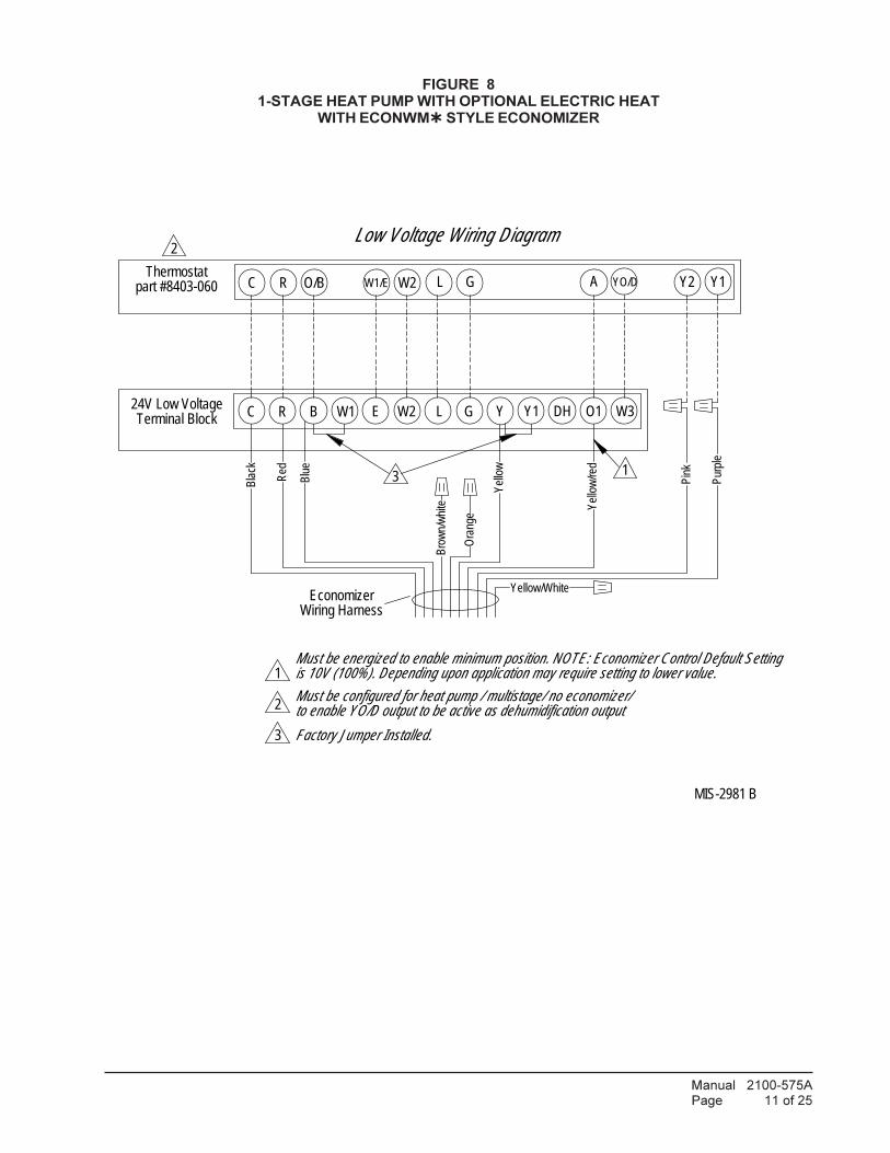
W1/E Y2
1 is 10V (100%). Depending upon application may require setting to lower value.
YO/D
C R B YE
Must be configured for heat pump / multistage/ no economizer/ 2
3
Low Voltage Wiring Diagram2
Y1
W2 L
24V Low VoltageW2
Terminal BlockW1
Wiring Harness
to enable YO/D output to be active as dehumidification output
L W3O1G
Thermostat
Factory Jumper Installed.
Economizer
part #8403-060 GR O/B
DH
C A
3 1
Must be energized to enable minimum position. NOTE: Economizer Control Default Setting
Y1
Yel
low
Bla
ck
Blu
e
Red
Yel
low
/red
Bro
wn/
whi
te
Pin
k
Pur
ple
Ora
nge
Yellow/White
MIS-2981 B
FIGURE 8
1-STAGE HEAT PUMP WITH OPTIONAL ELECTRIC HEAT
WITH ECONWM� STYLE ECONOMIZER

Manual 2100-575APage 12 of 25
R O/BC
Must be configured for heat pump and economizer
W1/E W2 L Y1
2
YO/D
Terminal BlockL
to enable YO/D output to be active as 1st-stage cooling
GC
2
GThermostat Y2
R B
1
Y1
A
E Y
Low Voltage Wiring Diagram
W2W1 O1DH24V Low Voltage
Factory Jumper Installed.
Economizer
3
part #8403-060
3
W3
Wiring Harness
1
Must be energized to enable minimum position. NOTE: Economizer Control Default Settingis 10V (100%). Depending upon application may require setting to lower value.
Bro
wn/
whi
te
Ora
nge
Pin
k
Pur
ple
Yel
low
Bla
ck
Blu
e
Red
Yel
low
/red
Yellow/White
MIS-2982 B
FIGURE 9
2-STAGE HEAT PUMP WITH OPTIONAL ELECTRIC HEAT
WITH ECONWM� STYLE ECONOMIZER

Manual 2100-575APage 13 of 25
YO/D
is 10V (100%). Depending upon application may require setting to lower value.
C R B Y1E YW2W1 O1DHTerminal Block
L W3G24V Low Voltage
2
1
Factory Jumper Installed.
2to enable YO/D output to be active as dehumidification outputMust be configured for heat pump / no economizer/
Wiring HarnessEconomizer
part #8403-060GR O/BC
Low Voltage Wiring Diagram
W1/E W2 L
3
Y2Thermostat
3
A
1
Must be energized to enable minimum position. NOTE: Economizer Control Default Setting
Y1R
ed
Pin
k
Pur
ple
Yel
low
Bla
ck
Blu
e
Ora
nge
Yel
low
/Red
Bro
wn/
whi
te
Yellow/White
MIS-2995 B
FIGURE 10
2-STAGE HEAT PUMP WITH DEHUMIDIFICATION & OPTIONAL ELECTRIC HEAT
WITH ECONWM� STYLE ECONOMIZER
Manual 2100-575APage 14 of 25
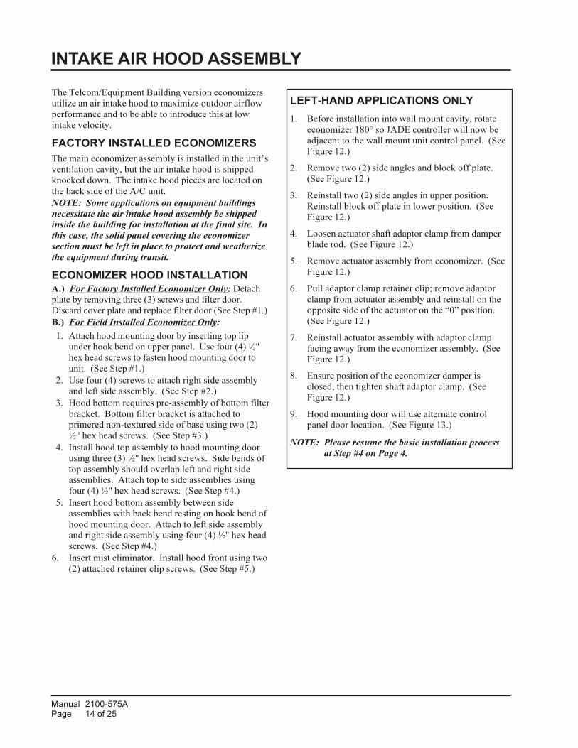
INTAKE AIR HOOD ASSEMBLY
The Telcom/Equipment Building version economizers
utilize an air intake hood to maximize outdoor airflow
performance and to be able to introduce this at low
intake velocity.
FACTORY INSTALLED ECONOMIZERS
The main economizer assembly is installed in the unit’s
ventilation cavity, but the air intake hood is shipped
knocked down. The intake hood pieces are located on
the back side of the A/C unit.
NOTE: Some applications on equipment buildings
necessitate the air intake hood assembly be shipped
inside the building for installation at the final site. In
this case, the solid panel covering the economizer
section must be left in place to protect and weatherize
the equipment during transit.
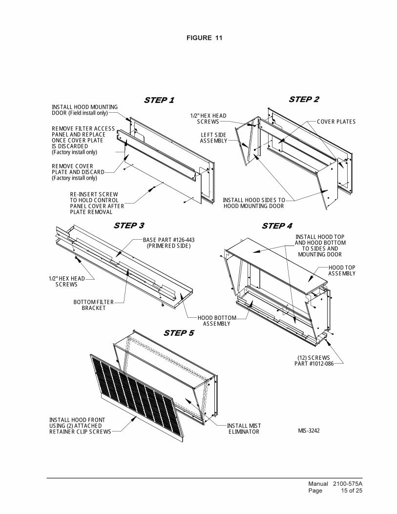
ECONOMIZER HOOD INSTALLATION
A.) For Factory Installed Economizer Only: Detach
plate by removing three (3) screws and filter door.
Discard cover plate and replace filter door (See Step #1.)
B.) For Field Installed Economizer Only:
1. Attach hood mounting door by inserting top lip
under hook bend on upper panel. Use four (4) ½"
hex head screws to fasten hood mounting door to
unit. (See Step #1.)
2. Use four (4) screws to attach right side assembly
and left side assembly. (See Step #2.)
3. Hood bottom requires pre-assembly of bottom filter
bracket. Bottom filter bracket is attached to
primered non-textured side of base using two (2)
½" hex head screws. (See Step #3.)
4. Install hood top assembly to hood mounting door
using three (3) ½" hex head screws. Side bends of
top assembly should overlap left and right side
assemblies. Attach top to side assemblies using
four (4) ½" hex head screws. (See Step #4.)
5. Insert hood bottom assembly between side
assemblies with back bend resting on hook bend of
hood mounting door. Attach to left side assembly
and right side assembly using four (4) ½" hex head
screws. (See Step #4.)
6. Insert mist eliminator. Install hood front using two
(2) attached retainer clip screws. (See Step #5.)
LEFT-HAND APPLICATIONS ONLY
1. Before installation into wall mount cavity, rotate
economizer 180° so JADE controller will now be
adjacent to the wall mount unit control panel. (See
Figure 12.)
2. Remove two (2) side angles and block off plate.
(See Figure 12.)
3. Reinstall two (2) side angles in upper position.
Reinstall block off plate in lower position. (See
Figure 12.)
4. Loosen actuator shaft adaptor clamp from damper
blade rod. (See Figure 12.)
5. Remove actuator assembly from economizer. (See
Figure 12.)
6. Pull adaptor clamp retainer clip; remove adaptor
clamp from actuator assembly and reinstall on the
opposite side of the actuator on the “0” position.
(See Figure 12.)
7. Reinstall actuator assembly with adaptor clamp
facing away from the economizer assembly. (See
Figure 12.)
8. Ensure position of the economizer damper is
closed, then tighten shaft adaptor clamp. (See
Figure 12.)
9. Hood mounting door will use alternate control
panel door location. (See Figure 13.)
NOTE: Please resume the basic installation process
at Step #4 on Page 4.
Manual 2100-575APage 15 of 25
FIGURE 11
ASSEMBLYHOOD TOP
STEP 4
INSTALL HOOD TOPAND HOOD BOTTOM
TO SIDES ANDMOUNTING DOOR
(12) SCREWSPART #1012-086
BRACKETBOTTOM FILTER
(PRIMERED SIDE)BASE PART #126-443
STEP 3
1/2" HEX HEADSCREWS
ASSEMBLYLEFT SIDE
STEP 2
HOOD MOUNTING DOOR
SCREWS1/2" HEX HEAD
INSTALL HOOD SIDES TO
COVER PLATES
INSTALL HOOD MOUNTING
REMOVE COVER
DOOR (Field install only)
(Factory install only)PLATE AND DISCARD
STEP 1
RE-INSERT SCREWTO HOLD CONTROLPANEL COVER AFTERPLATE REMOVAL
REMOVE FILTER ACCESSPANEL AND REPLACEONCE COVER PLATEIS DISCARDED(Factory install only)
STEP 5
RETAINER CLIP SCREWSUSING (2) ATTACHEDINSTALL HOOD FRONT
INSTALL MISTELIMINATOR MIS-3242
HOOD BOTTOMASSEMBLY

Manual 2100-575APage 16 of 25
FIGURE 12
JADE™ ECONOMIZER CONTROLLER
W7220 Controller offers unparalleled flexibility and
expansion in a dependable and solid electronic platform.
• Multiple economizer applications from one
controller.
• Nearly limitless customization of setpoints.
• Internal Checkout menu provides fast performance
assessment.
• Alarms menu provides assistance in
troubleshooting.
Memory: User defined setpoints remain in non-volatile
flash memory regardless of electrical outage duration.
Control voltage below 18V may cause erratic
performance.
LEFT HANDED APPLICATION
"0" POSITION
MIS-3224
ACTUATOR
DAMPER BLADE ROD
SHAFT ADAPTORCLAMP
LEFT HANDED ECONOMIZER
MOVE BLOCK
LOWER POSITION
BLADE IN CLOSED POSITION
OFF PLATE TO
MOVE SIDE ANGLES TO UPPER POSITION
Manual 2100-575APage 17 of 25
TABLE 2
SYSTEM SETUP (Menu Levels)
leveLuneMtluafeD
eulaVegnaR setoN
LLATSNI 01/10/10YY/DD/MM=redrOyalpsiDYY/MM/DD=redrOgnitteS
GEDSTINU F° C°/F°nidaerotrellortnocsteS
stnemerusaemrehtie
TNEMPIUQE )B(PH PHPHpmuPtaeH
C/A=VNOC
NIXUA )B(PH)O(PH)B(PH
looCnoezigrenEtaeHnoezigrenE
DEEPSNAF deepS1deepS1deepS2
MFCNAF 0005ot00100051
elbacilppatoN
TUOXUA 2HXE
ENONVRE
2HXESYS
otdesuebnactcudorPsecivedrehtolangis
CCO TUPNIroTUPNI
SYAWLA
detacidedrofsiTUPNIsiSYAWLA,langisCCO
snoitautisrehtollarof
YROTCAFTLUAFED
ONroSEY
ONfistluafedyrotcafotsteseR
SEYotdegnahc
START-UP / CHECKOUT PROCEDURES
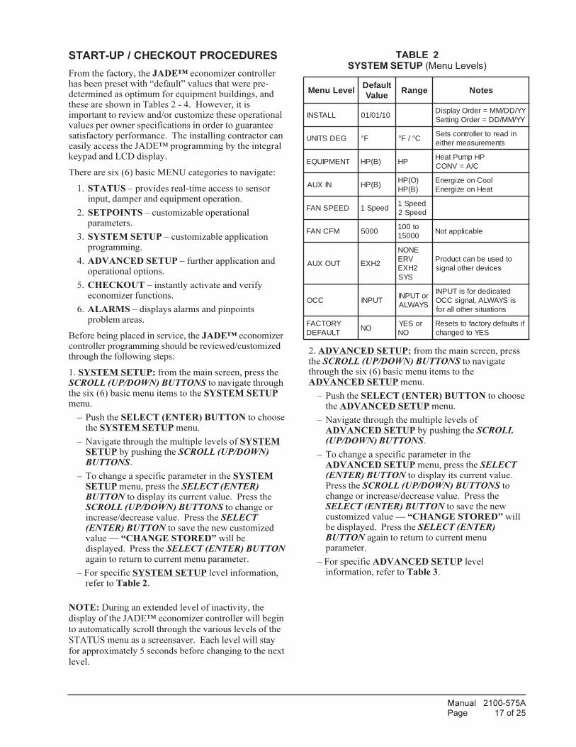
From the factory, the JADE™ economizer controllerhas been preset with “default” values that were pre-determined as optimum for equipment buildings, andthese are shown in Tables 2 - 4. However, it isimportant to review and/or customize these operationalvalues per owner specifications in order to guaranteesatisfactory performance. The installing contractor caneasily access the JADE™ programming by the integralkeypad and LCD display.
There are six (6) basic MENU categories to navigate:
1. STATUS – provides real-time access to sensorinput, damper and equipment operation.
2. SETPOINTS – customizable operationalparameters.
3. SYSTEM SETUP – customizable applicationprogramming.
4. ADVANCED SETUP – further application andoperational options.
5. CHECKOUT – instantly activate and verifyeconomizer functions.
6. ALARMS – displays alarms and pinpointsproblem areas.
Before being placed in service, the JADE™ economizercontroller programming should be reviewed/customizedthrough the following steps:
1. SYSTEM SETUP: from the main screen, press theSCROLL (UP/DOWN) BUTTONS to navigate throughthe six (6) basic menu items to the SYSTEM SETUPmenu.
– Push the SELECT (ENTER) BUTTON to choosethe SYSTEM SETUP menu.
– Navigate through the multiple levels of SYSTEMSETUP by pushing the SCROLL (UP/DOWN)BUTTONS.
– To change a specific parameter in the SYSTEMSETUP menu, press the SELECT (ENTER)BUTTON to display its current value. Press theSCROLL (UP/DOWN) BUTTONS to change orincrease/decrease value. Press the SELECT(ENTER) BUTTON to save the new customizedvalue — “CHANGE STORED” will bedisplayed. Press the SELECT (ENTER) BUTTONagain to return to current menu parameter.
– For specific SYSTEM SETUP level information,refer to Table 2.
NOTE: During an extended level of inactivity, the
display of the JADE™ economizer controller will begin
to automatically scroll through the various levels of the
STATUS menu as a screensaver. Each level will stay
for approximately 5 seconds before changing to the next
level.
2. ADVANCED SETUP: from the main screen, pressthe SCROLL (UP/DOWN) BUTTONS to navigatethrough the six (6) basic menu items to theADVANCED SETUP menu.
– Push the SELECT (ENTER) BUTTON to choosethe ADVANCED SETUP menu.
– Navigate through the multiple levels ofADVANCED SETUP by pushing the SCROLL(UP/DOWN) BUTTONS.
– To change a specific parameter in theADVANCED SETUP menu, press the SELECT(ENTER) BUTTON to display its current value.Press the SCROLL (UP/DOWN) BUTTONS tochange or increase/decrease value. Press theSELECT (ENTER) BUTTON to save the newcustomized value — “CHANGE STORED” willbe displayed. Press the SELECT (ENTER)BUTTON again to return to current menuparameter.
– For specific ADVANCED SETUP levelinformation, refer to Table 3.
Manual 2100-575APage 18 of 25
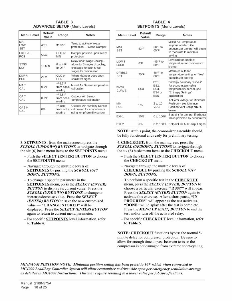
TABLE 3
ADVANCED SETUP (Menu Levels)TABLE 4
SETPOINTS (Menu Levels)
leveLuneMtluafeD
eulaVegnaR setoN
AMWOLTES
F°54 °55-53ezeerfetavitcaotpmeT
repmaDesolC—noitcetorp
EZEERFSOP
OLCroOLC
NIMezeerfnopunoitisoprepmaD
noitcetorp
3GTSYLD
NIM51h0.4ot0
FFOro
3rofyaleD dr –gnilooCegatS,gniloocfosegats3rofswolla
owt&nocerofegatsenorosserpmocrofsegats
RPMDSOP
OLCroOLC
NPOnopuseogrepmaderehW
langisnwodtuhs
TAMLAC
F°0.0F°5.2-/+
lautcamorfgnidaer
erutarepmetrosneSriAdexiMnoitarbilac
TAOLAC
F°0.0F°5.2-/+
lautcamorfgnidaer
rosneSriAroodtuOnoitarbilacerutarepmet
HSAOLAC
%0%01-/+
lautcamorfgnidaer
rosneSytidimuHriAroodtuOsrezimonocerofnoitarbilacrosnesytidimuh/pmetgnisu
leveLuneMtluafeD
eulaVegnaR setoN
TAMTES
F°35otF°83
F°56
erutarepmeTriAdexiMehthcihwtatnioptes
nigeblliwrepmadrezimonoceniatniamotetaludomot
gnittes
TWOLKCOL
F°0otF°54-
F°08
tneibmaroodtuowoLrosserpmocroferutarepmet
tuokcol
BLBYRDTES
F°07otF°84
F°08
roodtuomumixaM"eerf"rofgnitteserutarepmet
gniloocrezimonoce
HTNEEVRUC
3SE
,1SE,2SE,3SE
ro4SE5SE
"sevruc"yradnuobyplahtnEgnisusrezimonocerof
ees,rosnesytidimuh/pmet"sgnitteSyplahtnE"
noitanalpxe
NIMSOP
V0101ot2
CDV
muminiMrofegatlovrotautcAmuminiMees–noitisoP
puteStneVnoitisoP ETONwoleb
1HXE %05 %001ot0tsuahxefirepmadroftniopteSrezimonoceybderewopsinaf
2HXE %6 %001ot0 langistuptuoXUAroftniopteS
MINIMUM POSITION NOTE: Minimum position setting has been preset to 10V which when connected to
MC4000 Lead/Lag Controller System will allow economizer to drive wide open per emergency ventilation strategy
as detailed in MC4000 Instructions. This may require resetting to a lower value per job specifications.
3. SETPOINTS: from the main screen, press theSCROLL (UP/DOWN) BUTTONS to navigate throughthe six (6) basic menu items to the SETPOINTS menu.
– Push the SELECT (ENTER) BUTTON to choosethe SETPOINTS menu.
– Navigate through the multiple levels ofSETPOINTS by pushing the SCROLL (UP/DOWN) BUTTONS.
– To change a specific parameter in theSETPOINTS menu, press the SELECT (ENTER)BUTTON to display its current value. Press theSCROLL (UP/DOWN) BUTTONS to change orincrease/decrease value. Press the SELECT(ENTER) BUTTON to save the new customizedvalue — “CHANGE STORED” will bedisplayed. Press the SELECT (ENTER) BUTTONagain to return to current menu parameter.
– For specific SETPOINTS level information, referto Table 4.
NOTE: At this point, the economizer assembly should
be fully functional and ready for preliminary testing.
4. CHECKOUT: from the main screen, press theSCROLL (UP/DOWN) BUTTONS to navigate throughthe six (6) basic menu items to the CHECKOUT menu.
– Push the SELECT (ENTER) BUTTON to choosethe CHECKOUT menu.
– Navigate through the multiple levels ofCHECKOUT by pushing the SCROLL (UP/DOWN) BUTTONS.
– To perform a specific test in the CHECKOUTmenu, press the SELECT (ENTER) BUTTON tochoose a particular exercise, “RUN?” will appear.Press the SELECT (ENTER) BUTTON again toactivate this exercise. After a short pause, “INPROGRESS” will appear as the test activates.“DONE” will display after the test is complete.Press the MENU UP (EXIT) BUTTON to end thetest and/or turn off the activated relay.
– For specific CHECKOUT level information, referto Table 5.
NOTE: CHECKOUT functions bypass the normal 5-
minute delay for compressor protection. Be sure to
allow for enough time to pass between tests so the
compressor is not damaged from extreme short-cycling.
Manual 2100-575APage 19 of 25
TABLE 5
CHECKOUT (Menu Levels)TABLE 6
STATUS (Menu Levels)
metItuokcehC tseTtuokcehC
SH-NIMVREPMADfotnuomamuminimehtotrepmadsnoitisoP
rotautcaybdewollagninepo
SH-XAMVREPMADdetacidnilevelSOPNIMehtotrepmadsnepO
ehtni STNIOPTES muminiMeeS.unem)61.gP(erudecorPputeSnoitalitneVnoitisoP
NEPOREPMADsezigrene,noitisopnepollufotrepmadsecroF
stcatnoctsuahxe
ESOLCREPMAD noitisopdesolcyletelpmocotrepmadsnoitisoP
O-1YTCENNOC rosserpmocotTUPTUO-1YsecroF
O-2YTCENNOC rosserpmocotTUPTUO-2YsecroF
XUATCENNOC
morfgnittesTUOXUAnopugnidnepeD PUTES:unem
noitcaon–ENONrezimonocETON&VREroftuoCAV42–VRE
mralaroftuoCAV42–SYS
leveLuneM egnaR setoN
LIAVANOCE ON/SEYerasnoitidnocfisetacidnIgnizimonocerofelbarovaf
GNIZIMONOCE ON/SEYylevitcasirezimonocefisetacidnI
gnizimonoce
DEIPUCCO ON/SEYV42detacidedfisetacidnI
deviecergniebsilangisdeipuccoCCOlanimretno
PMUPTAEH TAEH/LOOCfiesurosserpmoclautcasyalpsiD
edomPMUPTAEHni
NI-1YLOOC FFO/NOgniebsilangisV42fisetacidnI
I-1Ylanimretnodeviecer
TUO-1YLOOC FFO/NOylevitcasirellortnocfisyalpsiD
rosserpmoclacinahcemrofgnillac)O-1YnoV42(gnilooc
NI-2YLOOC FFO/NOgniebsilangisV42fisetacidnI
I-2Ylanimretnodeviecer
TUO-2YLOOC FFO/NOylevitcasirellortnocfisyalpsiD
gnilooc2.gtSrofgnillac)O-2YnoV42(
PMETAM F°041ot°0 pmetriadeximtnerruC
PMETAO F°041ot°04- pmetriaroodtuotnerruC
MUHAO %001ot%0rofytidimuhriaroodtuotnerruC
ytidimuh/pmetgnisusrezimonocerosnes
TUOREPMAD 0.01ot0.2 rotautcaotegatlovsyalpsiD
SOPTCA %001ot0 gninepofo%tnerruC
TNUOCTCA A/NselcycrotautcafotnuoctnerruC
noitallatsnimorf
KOROTAUTCA ON/SEY tluaflaitnetopsetacidnI
TUO1HXE FFO/NO lanimreT1HXEfotuptuO
NOLOOCHCEM 2ro,1,0gnilooclacinahcemfosegatS
evitcayltnerruc
NOTE: Economizer assembly should be ready to put
into service. At any point during operation, in
economizer mode or idle, real-time information from
sensors and integral components can be accessed from
the STATUS menu.
5. STATUS: from the main screen, press the SCROLL(UP/DOWN) BUTTONS to navigate through the six (6)basic menu items to the STATUS menu.
– Push the SELECT (ENTER) BUTTON to choosethe STATUS menu.
– Navigate through the multiple levels of STATUSby pushing the SCROLL (UP/DOWN) BUTTONS.
– As the STATUS menu simply gives input/outputinformation in real-time, there is no way to changeor otherwise alter the displayed criteria. It issimply a window into the operation of theeconomizer controller.
– For specific STATUS level information, refer toTable 6.
NOTE: Upon power-up (or after power failure or low
voltage condition), the controller will begin a 5-minute
time delay before enabling mechanical cooling.
NOTE: If there are any potential problems recognized
by the economizer controller, it may be registered in the
form of an alarm in the ALARM(S) menu. If there is a
period of inactivity AND there is an alarm registering,
the controller will randomly scroll through the
ALARM(S) menu items as a screensaver.
Manual 2100-575APage 20 of 25
ENTHALPY SETTINGS
If economizer is enthalpy-based, and was shipped withthe temp/humidity sensor, the economizer must beprogrammed for the specific enthalpy curve boundarydesired for “free” outdoor cooling. The availableenthalpy boundaries are all subject to specific OAtemperature, OA humidity, and OA dew points. If all ofthe OA conditions are below the specific points outlinedin each boundary, the conditions are good to economizeand economizer mode is set to “YES”. If some or allthe OA conditions are above the specific points outlinedin each boundary, the conditions are not good toeconomize and the economizer mode is set to “NO”.
ES3 is Factory Default.
yplahtnEevruC
yrD.pmeT)F°(bluB
.pmeT)F°(tniopweD
yplahtnE)ad/bl/utb(
1PtnioP 2PtnioP
F°.pmeTytidimuH
HR%F°.pmeT
ytidimuHHR%
1SE 0.08 0.06 0.82 0.08 8.63 3.66 1.08
2SE 0.57 0.75 0.62 0.57 6.93 3.36 0.08
3SE 0.07 0.45 0.42 0.07 3.24 7.95 4.18
4SE 0.56 0.15 0.22 0.56 8.44 7.55 2.48
5SE 0.06 0.84 0.02 0.06 9.64 3.15 5.88
LH 0.68 0.66 4.23 0.68 9.83 4.27 3.08

Manual 2100-575APage 21 of 25
TABLE 7
ALARMS (Examples)
)s(mralA setoN
RRESNESTAM rosnesriadeximgninoitcnuflaM
RRESNESTAO rosnesriaroodtuogninoitcnuflaM
DELLATSTCA gninepofoegatnecrepderisedhcaertonnacrotautcA
MRALASYSlliwSYS,unemSTNIOPTESniSYSottessiXUAfI
mraladeretsigerynanopuyalpsid
ehtnopugnidnepedyalpsidlliwsmralalanoitiddA.smralafotsiletelpmocatonsisihT:ETON.tnempiuqedehcattadnanoitarugifnocdnasgnittesretemarap
ALARM(S): from the main screen, press the SCROLL
(UP/DOWN) BUTTONS to navigate through the six (6)basic menu items to the ALARM(S) menu.
– Push the SELECT (ENTER) BUTTON tochoose the ALARM(S) menu.
– Navigate through the current alarms in ALARM(S)by pushing the SCROLL (UP/DOWN) BUTTONS.
– Once the alarm has been identified, and the causehas been removed (e.g. replaced faulty sensor), thealarm may erase itself. If a manual alarm-erasing
is required, it can be cleared from the display bynavigating to the desired alarm and pressing theSELECT (ENTER) BUTTON to choose thatspecific alarm. “ERASE?” will display. Press theSELECT (ENTER) BUTTON again. “ALARMERASED” will appear. Press the MENU UP
(EXIT) BUTTON to complete the action and returnto the previous menu.
– For specific ALARM(S) information, refer toTable 7.

Manual 2100-575APage 22 of 25
FIGURE 13
100% OUTSIDE AIRFLOW PATH
FIGURE 14
MIXED AIRFLOW PATH
RETURN AIR
SUPPLY AIRCOOLING COIL
EXHAUST AIROUTDOOR AIR
CONDENSER AIR
ELIMINATOR
AIR FILTER
MIST
CONDENSER COILMIS-2936 B
MIS-2938 B
ELIMINATOR
RETURN AIR
SUPPLY AIR
OUTDOOR AIR
MIST AIR FILTER
EXHAUST AIR
ECONOMIZER SEQUENCE OF
OPERATION
Condition — Cool / Dry OA Conditions
• 1st Stage Cooling closes and sends signal toJADE™ control. Since the air temperatureoutside is cooler than the preset DRYBULB SETsetting, or is below the ENTH CURVE boundaryin the SETPOINTS menu, the actuator will powerthe economizer damper to “economizer” mode asthe indoor blower motor starts. The mixed airsensor senses a mixture of return air and cooloutdoor air and modulates opening to achievepreset MAT SET setting in SETPOINTS menu.Compressor operation is inhibited. (See Figure 13.)
• 2nd Stage Cooling closes and sends a signal toJADE™ control, which closes the Y1-O relay tobegin mechanical cooling. The economizerdamper REMAINS OPEN in tandem operationwith the compressor as long as the OA conditionsdo not drop below the preset DRYBULB SET/ENTH CURVE settings in the SETPOINTSmenu. (See Figure 14.)
• 3rd Stage Cooling (if available) closes and sends asignal to JADE™ control, which closes the Y2-Orelay to begin 2nd stage mechanical cooling. Theeconomizer damper REMAINS OPEN intandem operation with the compressor as longas the temperature outside does not drop below thepreset DRYBULB SET setting in theSETPOINTS menu. (See Figure 14.)
Condition — Warm / Humid OA Conditions
• 1st Stage Cooling closes and sends signal toJADE™ control. Since the OA conditions areabove the preset DRYBULB SET/ENTH CURVEsetting in the SETPOINTS menu, the control willsimply close the Y1-O relay to initiate mechanicalcooling. The economizer damper will remainclosed or in a minimum ventilation settingdepending upon occupied status. (See Figure 15.)
• 2nd Stage Cooling (if available) closes and sends asignal to JADE™ control. Since the OAconditions are still above than the presetDRYBULB SET/ENTH CURVE setting in theSETPOINTS menu, the control will simply closethe Y2-O relay to initiate 2nd stage mechanicalcooling. The economizer damper will remainclosed or in a minimum ventilation settingdepending upon occupied status. (See Figure 15.)
Manual 2100-575APage 23 of 25
FIGURE 15
100% CLOSED LOOP AIRFLOW PATH
100% RETURN AIR
DAMPER BLADE
SUPPLY AIR
ELIMINATOR
AIR FILTER
CONDENSER AIR
COOLING COIL
MIST
CONDENSER COILMIS-2937 B
ECONOMIZER FEATURES
• One piece construction – easy to install. Direct-drive actuator eliminates linkage.
• Exhaust air damper – built in with positive closedposition. Provides exhaust air capability toprevent pressurization of tight buildings.
• JADE™ controller provides nearly limitlesscustomization on a solid, intuitive electronicplatform.
• Actuator Motor – 24 volt, power-open, spring-return, direct-coupled with stall protection. Self-centering shaft clamp and access cover facilitateease of replacement/maintenance.
• Proportioning-type control – for maximum “free”cooling economy and comfort with up to 100%outside air.
• Drybulb sensor to monitor outdoor air temperature.
• Minimum Ventilation Position available forrequired ventilation of occupants or dilution ofpollutants.
• Mixed air sensor to monitor outdoor and return airto automatically modulate damper position.

Manual 2100-575APage 24 of 25
THERMOSTAT/CONTROL CALLS
FOR 1ST
STAGE COOLING
OA CONDITIONS
ABOVE DRYBULB
OR ENTHALPY
CURVE SETPOINTS
OA CONDITIONS
BELOW DRYBULB
OR ENTHALPY
CURVE SETPOINT
ECONOMIZER ONLY
OPERATION, MAT
SENSOR ATTEMPTS
TO MAINTAIN
PRESET DISCHARGE
AIR TEMP.
IS ADDITIONAL
MECHANICAL
COOLING BEGINS,
ECON. DAMPER
CLOSED OR MIN.
POSITION
CONDITIONED
SPACE LOAD IS
PICKED UP BY
MECHANICAL
COOLING
THERMOSTAT IS
SATISFIED AND
SYSTEM SHUTS
DOWN
CONDITIONED
SPACE LOAD IS
PICKED UP BY
ECONOMIZER
NO YES
THERMOSTAT IS
SATISFIED AND
SYSTEM SHUTS
DOWN
MECHANICAL
COOLING BEGINS,
ECON DAMPER
REMAINS OPEN
CONDITIONED
SPACE LOAD IS
PICKED UP BY
ECONOMIZER AND
MECHANICAL COOL
THERMOSTAT IS
SATISFIED AND
SYSTEM SHUTS
DOWN
Economizer Operation for Single Stage:
Manual 2100-575APage 25 of 25
THERMOSTAT/CONTROL CALLS
FOR 1ST
STAGE COOLING
OA CONDITIONS
ABOVE DRYBULB
OR ENTHALPY
CURVE SETPOINT
OA CONDITIONS
BELOW DRYBULB
OR ENTHALPY
CURVE SETPOINT
ECONOMIZER ONLY
OPERATION, MAT
SENSOR ATTEMPTS
TO MAINTAIN
PRESET DISCHARGE
AIR TEMP.
IS ADDITIONAL
1ST
STAGE
MECHANICAL
COOLING BEGINS,
ECON. DAMPER
CLOSED OR MIN.
POSITION
IS ADDITIONAL
2ND
STAGE
MECHANICAL
COOLING BEGINS,
ECON DAMPER
CLOSED OR MIN.
POSITION
CONDITIONED
SPACE LOAD IS
PICKED UP BY
MECHANICAL
COOLING
YES NO
CONDITIONED
SPACE LOAD IS
PICKED UP BY
MECHANICAL
COOLING
THERMOSTAT IS
SATISFIED AND
SYSTEM SHUTS
DOWN
CONDITIONED
SPACE LOAD IS
PICKED UP BY
ECONOMIZER
NO YES
THERMOSTAT IS
SATISFIED AND
SYSTEM SHUTS
DOWN
1ST STAGE
MECHANICAL
COOLING BEGINS,
ECON DAMPER
REMAINS OPEN
IS ADDITIONAL
COOLING
CONDITIONED
SPACE LOAD IS
PICKED UP BY
ECONOMIZER AND
MECHANICAL COOL
NO
2ND
STAGE
MECHANICAL
COOLING BEGINS,
ECON DAMPER
REMAINS OPEN
YES
CONDITIONED
SPACE LOAD IS
PICKED UP BY
ECONOMIZER AND
MECHANICAL COOL
THERMOSTAT IS
SATISFIED AND
SYSTEM SHUTS
DOWN
Economizer Operation for Two Stage: