INSTALLATION MANUAL WHISPER 6 / 8 / 12 6 ULTRA Mastervolt Whisper 8.pdf · Whisper generating sets...
28
MASTERVOLT Snijdersbergweg 93 1105 AN Amsterdam The Netherlands Tel.: +31-20-3422100 Fax: +31-20-6971006 http://www.mastervolt.com INSTALLATION MANUAL V2. October 2004 WHISPER 6 / 8 / 12 6 ULTRA -3000 / 1500 RPM- Marine diesel generating set 230V-50Hz Digital Diesel Control Art.nr. 50200361
-
Upload
trinhduong -
Category
Documents
-
view
274 -
download
3
Transcript of INSTALLATION MANUAL WHISPER 6 / 8 / 12 6 ULTRA Mastervolt Whisper 8.pdf · Whisper generating sets...

MASTERVOLTSnijdersbergweg 931105 AN AmsterdamThe NetherlandsTel.: +31-20-3422100Fax: +31-20-6971006http://www.mastervolt.com
INSTALLATION MANUAL
V2. October 2004
WHISPER 6 / 8 / 126 ULTRA
-3000 / 1500 RPM-
Marine diesel generating set 230V-50Hz
Digital Diesel Control
Art.nr. 50200361

2 October 2004 / WHISPER 6/8/12 & 6 ULTRA / EN
This manual applies to the Mastervolt Whisper 6/8/12 and 6 ULTRA Marine
Diesel Generating set controlled by Digital Diesel Control first launched in April
2004. For earlier models refer to other manuals available on our website: www.
mastervolt.com
CONTENTS
1 INSTALLATION . . . . . . . . . . . . . . . . . . . . . . . . . . . . . . . . . . . . . . . . . . . . . . . . . . . . . . . . . . . . . . . . . . . . . . . . . . . . .31.1 Location . . . . . . . . . . . . . . . . . . . . . . . . . . . . . . . . . . . . . . . . . . . . . . . . . . . . . . . . . . . . . . . . . . . . . . . . . . . . . .31.2 Instructions for optimal sound and vibration insulation . . . . . . . . . . . . . . . . . . . . . . . . . . . . . . . . . . . . . . . . . .3
1.2.1 Steel base plate . . . . . . . . . . . . . . . . . . . . . . . . . . . . . . . . . . . . . . . . . . . . . . . . . . . . . . . . . . . . . . . . . .31.2.2 Further recommendations . . . . . . . . . . . . . . . . . . . . . . . . . . . . . . . . . . . . . . . . . . . . . . . . . . . . . . . . . .3
1.3 Ventilation . . . . . . . . . . . . . . . . . . . . . . . . . . . . . . . . . . . . . . . . . . . . . . . . . . . . . . . . . . . . . . . . . . . . . . . . . . . .31.4 Connections . . . . . . . . . . . . . . . . . . . . . . . . . . . . . . . . . . . . . . . . . . . . . . . . . . . . . . . . . . . . . . . . . . . . . . . . . .4
1.4.1 Fuel supply . . . . . . . . . . . . . . . . . . . . . . . . . . . . . . . . . . . . . . . . . . . . . . . . . . . . . . . . . . . . . . . . . . . .41.4.2 Cooling . . . . . . . . . . . . . . . . . . . . . . . . . . . . . . . . . . . . . . . . . . . . . . . . . . . . . . . . . . . . . . . . . . . .71.4.3 Exhaust system . . . . . . . . . . . . . . . . . . . . . . . . . . . . . . . . . . . . . . . . . . . . . . . . . . . . . . . . . . . . . . . .91.4.4 Digital Diesel Control system 12 Volt . . . . . . . . . . . . . . . . . . . . . . . . . . . . . . . . . . . . . . . . . . . . . . .121.4.5 AC power system 230 Volt (120 Volt) . . . . . . . . . . . . . . . . . . . . . . . . . . . . . . . . . . . . . . . . . . . . . .13
2 INSTALLATION SPECIFICATIONS . . . . . . . . . . . . . . . . . . . . . . . . . . . . . . . . . . . . . . . . . . . . . . . . . . . . . . . . . . . . .152.1 Installation table . . . . . . . . . . . . . . . . . . . . . . . . . . . . . . . . . . . . . . . . . . . . . . . . . . . . . . . . . . . . . . . . . . . . . .152.2 Commission table . . . . . . . . . . . . . . . . . . . . . . . . . . . . . . . . . . . . . . . . . . . . . . . . . . . . . . . . . . . . . . . . . . . . .162.3 Technical data . . . . . . . . . . . . . . . . . . . . . . . . . . . . . . . . . . . . . . . . . . . . . . . . . . . . . . . . . . . . . . . . . . . . . . . .172.4 Specification of the accessories . . . . . . . . . . . . . . . . . . . . . . . . . . . . . . . . . . . . . . . . . . . . . . . . . . . . . . . . . .172.5 Installation materials . . . . . . . . . . . . . . . . . . . . . . . . . . . . . . . . . . . . . . . . . . . . . . . . . . . . . . . . . . . . . . . . . . .18
3 DIAGRAMS AND DRAWINGS . . . . . . . . . . . . . . . . . . . . . . . . . . . . . . . . . . . . . . . . . . . . . . . . . . . . . . . . . . . . . . . . .223.1. DC wiring diagram . . . . . . . . . . . . . . . . . . . . . . . . . . . . . . . . . . . . . . . . . . . . . . . . . . . . . . . . . . . . . . . . . . .223.2. Codes and colors . . . . . . . . . . . . . . . . . . . . . . . . . . . . . . . . . . . . . . . . . . . . . . . . . . . . . . . . . . . . . . . . . . .233.3 Wiring diagram electronic governor (optional) . . . . . . . . . . . . . . . . . . . . . . . . . . . . . . . . . . . . . . . . . . . . . . . .243.4 AC wiring diagram Whisper 230V 50Hz . . . . . . . . . . . . . . . . . . . . . . . . . . . . . . . . . . . . . . . . . . . . . . . . . . . .253.5 Remote panel dimensions . . . . . . . . . . . . . . . . . . . . . . . . . . . . . . . . . . . . . . . . . . . . . . . . . . . . . . . . . . . . . . .263.6 Whisper 6/8/12 and 6 ULTRA dimensions . . . . . . . . . . . . . . . . . . . . . . . . . . . . . . . . . . . . . . . . . . . . . . . . . . .27
CONTENTS
EN / WHISPER 6/8/12 & 6 ULTRA / October 2004 3
1 INSTALLATION
To ensure reliability and durability of the equipment, it isvery important that the installation is carried out with theutmost care and attention. To avoid problems, such astemperature problems, noise levels, vibration, etc. theinstructions set out in this manual must be followed andall installation work must be carried out professionally.
1.1 LOCATION
Since Whisper generating sets have extremely compactdimensions, they can be installed in tight locations. Plea-se consider that even almost maintenance-free machi-nery must still remain accessible.When selecting the location area to mount the generatingset, make sure there is sufficient room to carry out anymaintenance work. The unit must be easily accessible onthe service side and on the distribution side to have ac-cess to the V-belt.Please also note that in spite of the automatic oil pressu-re sensor it is still essential that the oil level is checkedregularly.
1.2 INSTRUCTIONS FOR OPTIMAL SOUND
AND VIBRATION INSULATION
Position the generating set as low as possible in thevessel. As the generating set already has secured to thebase frame by means of flexible engine mountings, theframe can be mounted directly to the vessel’s main struc-ture.
1.2.1 Steel base plate
However to keep resonant vibrations at a minimum, it ispossible to mount the generating set on a solid steel baseplate, approx. 20 mm (3/4") weighing approx. 60 kg or50% of the weight of the generating set. The enginedraws its inlet combustion air through several holes in thecapsule base. Therefore the capsule must be fitted withsufficient clearance between the capsule underside andthe base plate. For the Whisper 6/8-3000rpm a steelbase plate is available with Mastervolt as an optionalaccessory (ref. fig. 12, page 36).
1.2.2 Further recommendations
Whisper generating sets are standard equipped with a"GRP" (Glass Reinforced Plastic) sound cover. The ca-nopy has been designed to give an effective sound insu-lation. For optimum sound and vibration dampening, the
following factors should be considered.
1 Avoid mounting the generating set in close proximityto thin walls or floors as that may resonate.
2 Sound dampening is extremely poor if the generatingset is mounted on alight weight flimsy surface suchas plywood which will only amplify vibrations. Ifmounting on a thinner surface cannot be avoided, thisshould at least be reinforced with stiffening struts orribbing. If possible, holes should be drilled or cutthrough the surface to help reduce the resonance.Covering the surrounding walls and floors with aheavy coating plus foam will certainly improve thesituation.
3 Never connect the base of the generating set directlyto bulkheads or tanks.
1.3 VENTILATION
The generating set normally draws air from the engineroom. Engine rooms with natural ventilation must havevent openings of adequate size and location to enablethe generating set to operate without overheating. Toallow an ample supply of air within the temperature limitsof the generating set an opening of at least 100 cm2 is re-quired.A "sealed" engine compartment must have a goodextraction ventilator to maintain reasonable engine roomtemperatures. High temperature of intake air reducesengine performance and increases engine coolant tem-peratures. Air temperatures above 40°C reduce the engi-ne power by 2% for each 5°C of rise. To minimise theseeffects the engine room temperature must not be morethan 15ºC above the outside ambient air temperature.Apply a combination of ventilators, blowers and air intakeducting to meet the temperature limit. The air inlet ductsshould run to the bottom of the engine room to clearfumes from the bilge and to circulate fresh air. Air outletsshould be at the top of the engine room to remove thehottest air. An engine room blower should be used as anextraction ventilator to remove air from the engine room.In cases where it is impossible to meet the above mentio-ned temperature limit by using machine room ventilation,connections are to be made for an air inlet directly to theenclosure. With these connection the generating set canbe directly connected to an air duct.
INSTALLATION

4 October 2004 / WHISPER 6/8/12 & 6 ULTRA / EN
INSTALLATION
Air inlets should be louvered, where appropriate, to pro-tect the engine room and to protect the generating setfrom water spray. As an extra precaution, the fitting of acowl ventilator with dorade box located as high as possi-ble, is recommended.
1.4 CONNECTIONS
The generating set comes supplied with all supply linesand output cable (i.e. electric cables, cooling water con-nections, exhaust, fuel lines etc.) already connected tothe engine and generator. The supply lines are fed throughthe capsule’s base. The connections are marked as shownin fig. 1.All electrical connections, cable types and sizes mustcomply to the appropriate national regulations. Suppliedcables are rated for ambient temperatures up to 70°C. Ifthe cables are required to meet higher temperature requi-rements, they must be run through conduits.
ATTENTION!Before working (installation) on the systemread the section safety instructions.
1.4.1 Fuel supply
1 FUEL TANK
Fuel tanks should be made of appropriate materialsuch as (stainless) steel or plastic. Steel tanks shouldnot be galvanised or painted inside. Condensationcan occur in metal tanks when temperature changes.Therefore, water accumulates at the bottom of thetank and provisions should be made for the drainageof this water.The tank will need a filling connection, a return con-nection and an air ventilation connection which willrequire protection against water entry.Some official regulations do not allow connectionpoints at the base of the fuel tank; in this instanceconnections are to be made at the top of the tank withinternal tubing down to a few cm above the bottom ofthe tank.
EXHAUST (1) 40 mm
REMOTE CABLE (2)12x0,3 mm2
AC CABLE (3)FUEL RETURN (6)
16 mm2BATTERY - (7)
8 mm
FUEL IN (4) 8 mm
16 mm2BATTERY + (5)
AIRVENT IN (10) 19 mm
AIRVENT OUT (9)
WATER IN (8) 19 mm
19 mm
40 mm 40 mmEXHAUST (1)EXHAUST (1)
REMOTE CABLE (2)
AC CABLE (3)12x0,3 mm2
FUEL RETURN (6)
WATER IN (8) 19 mm
8 mm
BATTERY + (5)25 mm2
8 mmFUEL IN (4)
AIRVENT OUT (9) 19 mmBATTERY - (7)25mm2
19 mmAIRVENT IN (10)
Afb. 1.
WHISPER 6/8
WHISPER 12/6 ULTRA

EN / WHISPER 6/8/12 & 6 ULTRA / October 2004 5
2 FUEL LIFT PUMP
The generating set itself is equipped with a fuel liftpump; therefore the tank can be installed at a lowerlevel than the generating set. The maximum suctionheight is 1 m.If the pump has to lift the fuel higher than one meteran external fuel lift pump must be installed. The con-trol board is already prepared to connect an extra fuelpump.
3 FUEL PIPES
When the tank is above the generating set we recom-mend to end the return line on the top of the tank.When the return is on the top - in case of a leakage -the return line cannot overflow because of siphoning.One will only need a fuel cock in the fuel supply line.
Fig. 2.
1 Fuel return;2 Fuel supply;3 Prefilter / water separator (optional);5 Fuel tank;
INSTALLATION

6 October 2004 / WHISPER 6/8/12 & 6 ULTRA / EN
INSTALLATION
When the tank is below the generating set we recom-mend to end the return line on the bottom of the tank(A) below the inlet of the supply line to dischargeunder the lowest fuel level. This prevents air gettinginto the fuel line. Here also one need only a fuel cockin the supply line.
Both supply and return fuel pipe lines should beappropriate material and 8 mm outer diameter tubing.The quality of the tubing of fuel pipes could be sub-mitted to local regulations depending on the applica-tion of the vessel.The fuel pipes can be plumbed to the flexible hoseswhich are on the generating set and have a connec-tion to fit to 8 mm pipe. This fuel lines fulfils CEstandards and are according to ISO 7840 A2.It is important to avoid bends in the pipes, as theycould trap air bubbles. The return pipe should neverbe connected to the suction pipe. Other consumers ofdiesel fuel, such as the propulsion engine and hea-ters, have to be connected to separate suction andreturn pipes
4 FUEL FILTERS
A fine fuel filter is installed which requires maintenan-ce. Mastervolt advises to install an extra fuel filter/water fuel separator near the fuel tank.Before starting your generating set for the first timefollow the fuel system bleeding procedure in the usersmanual.
Fig. 3.
1 Fuel return;2 Fuel supply;3 Prefilter / water separator (optional);4 Extra fuel lift pump (optional);5 Fuel tank.

EN / WHISPER 6/8/12 & 6 ULTRA / October 2004 7
1.4.2 Cooling
Intercooling is based on a raw water pump, heat exchan-ger and water-injected exhaust. Cooling liquid in theinternal cooling system is cooled in a heatexchanger byoutboard water (raw water or seawater). After the rawwater is warmed up in the heatexchanger it is dumpedoverboard by injecting it in the exhaust.The generating set should have its own sea water(coolant water) inlet and should not be connected to any other engine systems. A properly installed cooling systemis critical to keep engine temperatures within an accepta-ble range. Ensure that the installation complies to thefollowing installation instructions.
1 THE INTERNAL COOLING SYSTEM
The internal cooling system should be filled withcooling liquid. (Refer to the users manual 2.5.12)When the engine becomes hot the liquid expands andthe system is pressurised. After the pressure becomesto high the release valve in the filling cap on themanifold opens and the expanding liquid is pressedinto the expansion tank that is in the delivery. Also theair in the system that is collected at the top of themanifold is released in this way. When the liquid coolsdown there will be underpressure. An other valveopens and the liquid is sucked into the manifold again.This system works only when there is enough liquidinitially. This has to be checked when commissioningthe generator set. By filling up the expansion tankwhen necessary there will always be enough liquid inthe system. The hose that is in the delivery has to beconnected to the connection on the side of the fillingcap. This hose is made of heat resistant plastic and isnot sensitive for kinks.
The hose goes through a hole that has to be drilled inthe lower part of the canopy close to the place wherethe tank is mounted.
The tank has to be placed close to the generator.When it is mounted above the top of the manifold theliquid in the tank will be drained when the cap on themanifold is taken off.When keel cooling or radiator cooling is applied thesystem will not be pressurised. A cap without releasevalve should be applied. Refer to the special manualfor these applications.
2 RAW WATER SUPPLY
For raw water supply the following installation mate-rials are required: -a skin fitting - a sea cock - a waterstrainer - hoses and clamps. In order to keep the suc-tion resistance in the line at a minimum, the sea waterintake system (i.e. sea cock, tru-hull fitting, inlet filter,etc.) must have an inner diameter of at least 19 mmdiameter (3/4"). The suction hose should be kept asshort as possible. Raw water plumbing should avoidbends as much as possible.
1
2
3 4
5
7
6Min.24"
60 cm
2"5 cmMax.
60"150 cm
Min.24"
60 cm
Fig. 4b. 1 Water level;2 Water/exhaust separator;3 Seacock;4 Waterlock;
5 Air vent;6 Water strainer;7 Seacock.
Afb. 4a.
INSTALLATION

8 October 2004 / WHISPER 6/8/12 & 6 ULTRA / EN
INSTALLATION
Restriction of raw water flow, caused by kinked hoses,undersized pipes or connections, will reduce theengine cooling capability. This is the main cause foroverheating of an engine.After running the generating set for the first time, checkthe coolant flow rate using a stopwatch and by holdinga pail of a known volume under the wet exhaust outlet.The flow rate should be according to the data in theusers manual.
3 INSTALLATION OF THROUGH HULL FITTING
It is good practice for yachts to use a hull inlet fittingwith an integrated strainer (water scoop). For propul-sion engines in motorboats the water scoop is oftenmounted against the sailing direction to induce morewater intake for cooling.
This should not be done in the case of agenerating set! When ailing at higherspeeds, water will be forced into the inletand your generating set will overflow!
On motorboats and on sailing boats the water scoopfor a generating set should be fitted with the openingfaced backwards to prevent water being forced induring sailing.
4 WATER STRAINER
Use an appropriate water strainer with connections of19 mm (3/4"). Install the water strainer in a well ac-cessible position, (ref. to fig. 4 - 6) 15 cm above thewaterline.
5 SIPHON BREAKER (AIR VENT)
When the point of water injection is below the water-line, then - when the engine is stopped - there is arisk that the cooling water may enter the engine as aresult of siphoning. To avoid this happening, the ge-nerating set is designed to accommodate a siphonbreaker (air vent). In the standard delivery the con-nections are bypassed. Hose of 19 mm (3/4") innerdiameter should be used.
If the generating set cannot be mounted such that thebottom of the generating set is placed above thewaterline, an air vent must be installed. Extend the water hose of the by-pass 600 mm abovewaterline and install an air vent. Ideally, the air ventshould be mounted above the yacht keel center line(i.e. to minimize the influence of swaying on the waterintake). The hose of the drain should go downwards.Water must flow out freely; air must flow in freely aswell.Fast motorboats will lay deeper when sailing at largespeed and can cause pressure on the waterinlet. Thisshould be avoided to prevent fleeding the engine.
If the air vent is clogged the water hoseswill not be vented when the generating sethas stopped and water can be forced intothe engine. This leads to immediate engineproblems and eventually severe damage!
DAMAGE CAUSED BY THE INGRESS OF WATER
INTO THE ENGINE IS NEVER COVERED BY
WARRANTEE.
On the valve is a little hose to drain a little water thatcould be spilled from the valve. This hose should godown and may not end under water, because itshould ventilate air into the valve to break thesiphoning.
flow direction
sailing direction
WRONG!
thru-vessel inlet
Fig. 5.
Fig. 6.

EN / WHISPER 6/8/12 & 6 ULTRA / October 2004 9
Check the air vent at regular intervals. Open, cleanand lubricate the valve as required.
1.4.3 Exhaust system
Water is injected in the exhaust system of the generatingset. In this way the cooling water that has passed theheat exchanger is mixed with the exhaust gases.Temperature and volume of the gases are therebyreduced considerably, so that a rubber exhaust hose canbe used and the level of noise is reduced as well.
1 STANDARD EXHAUST SYSTEM INSTALLATION
The generating set exhaust system must remaincompletely independent and separate from the ex-haust system of any other engine on board. A waterlock prevents the generating set from being floodedby outside sea water and should be installed as closeto the generating set as possible. The lock must belarge enough to hold the entire water volume held inthe hose from the top of the goose neck to the waterlock. The water lock must be installed at the lowestpoint of the exhaust system (ref. to fig. 7-1). The ex-haust hose must have an inner diameter of 40 mm.The exhaust system must be installed so that theback pressure inside the exhaust does not exceed0.07 bar (1 psi = 70 cm watercolumn) and total lengthfrom generator to the top of the goose neck orwater/gasseparator does not exceed 3m (10 ft.).(Refer to paragraph 5.4.3 of the users manual.
The exhaust hose descends from the capsule to thewater lock. Then the hose rises via the "goose neck"to the through-hull exhaust outlet, situated minimum 50 mm above the water line (ref. to fig. 7-5. The"goose neck" must be vertical and situated preferablealong the ship’s keel center line. If the generating setis mounted less than 600 mm (24") above thewaterline, a "goose neck" must be installed to preventthe engine from overflowing. It is recommended toinstall an extra muffler close to the through-hull fitting.
A
B
Minimal24"
60 cm.
Maximal60"
150 cm.
max. length A - B = 10 ft. (3 m.)
2"5 cm.
Fig. 7.
1 Exhaust water lock;2 Exhaust outlet muffler;3 Exhaust line Ø 40 mm;
4 Goose neck5 Through-hull exhaust outlet Ø 40 mm;6 Water level.
INSTALLATION

10 October 2004 / WHISPER 6/8/12 & 6 ULTRA / EN
INSTALLATION
2 "SUPER SILENT" EXHAUST SYSTEM
In order to reduce the noise level of the generatingset to a minimum, an option to reduce the exhaustnoise further (especially exhaust water splashing) isan exhaust/water separator. The exhaust/water sepa-rator allows the cooling water to be ejected through aline (A) separate from the exhaust fumes and alsofunctions as a goose neck to prevent water fromflooding the engine. If the exhaust/water separator ismounted more than 600 mm above the water level anadditional goose neck is not required.
If the through-hull exhaust outlet has to be mountedfar (total length exhaust piping from generator to topof goose neck (waterseparator) is more than 3 m)from the generating set, an exhaust/water separatormust definitely be installed. The sea water from the
separator must then run down along the shortest pos-sible path to the through-hull outlet. Only after theexhaust/water separator the exhaust hose may havealength of over 7,5 m if the exhaust hose diameter isalso increased from 40 mm to 50 mm in order to re-duce the back pressure (ref. to fig. 9). Hohwever watertraps should be avoided as thefumes still contains water and this should notaccumulate in bents. (Refer to fig 8a) An additionaloutlet exhaust muffler close to the hull outlet will helpfurther to reduce noise emission.
waterlevel
max. 150 cm.
min. 60 cm.
40 mm
40 mm
40 mm
Amax. 10 cm
Fig. 8.
Fig. 8a.

EN / WHISPER 6/8/12 & 6 ULTRA / October 2004 11
A
BMax. length A - B = 3 m.
ø 40 mmø 40 mm
up to 3 m. ø 40 mm3-10 m. ø 50 mm
Fig. 9.
Fig. 10.
If the generating set and the exhaust system havebeen installed correctly, neighboring boats will not bedisturbed by generating set noise, With the "supersilent" exhaust system, generating set noises arealmost inaudible. For optimal noise reduction, the seawater outlet from the exhaust/water separator (centeroutlet on the unit) should be installed below the waterlevel to eliminate noisy splashing of the effluent seawater.The through-hull outlet for the exhaust fumes shouldnot direct the fumes directly toward the water surfaceas this will cause excessive noise (ref. to fig. 10).
Do not direct the outlet directly toward thewater surface.
INSTALLATION
12 October 2004 / WHISPER 6/8/12 & 6 ULTRA / EN
INSTALLATION
1.4.4 Digital Diesel Control system (12 Volt)
1 DIGITAL DIESEL CONTROL SYSTEM
The electrical control system is standard in 12 Voltwith negative earth. Non- earth return is available asan option for aluminium vessels to prevent corrosion. All electrical wiring has been prepared on the genera-ting set to the control panel prior to despatch from thefactory. The engine is controlled by a very advancedmicroprocessor based system: Digital Diesel Control.The “black box” containing the microprocessor islocated on top of the alternator.A local control panel is on the generating set.
Remote control
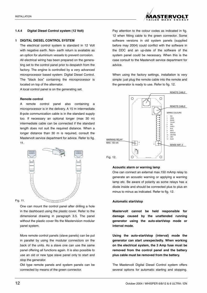
A remote control panel also containing amicroprocessor is in the delivery. A 15 m intermediate8-pole communication cable is in the standard supplytoo. If necessary an optional longer (max 30 m)intermediate cable can be connected if the standardlength does not suit the required distance. When alonger distance than 30 m is required, consult theMastervolt service department for advice. Refer to fig.11.
One can mount the control panel after drilling a holein the dashboard using the plastic cover. Refer to thedimensional drawing in paragraph 3.5. The panelwithout the plastic cover fits the Mastervision modularpanel system.
More remote control panels (slave panels) can be putin parallel by using the modular connectors on theback of the units. As a slave one can use the samepanel offering all functions again. It is also possible touse an old or new type slave panel only to start andstop the generator.Old type remote panels and system panels can beconnected by means of the green connector.
Pay attention to the colour codes as indicated in fig.12 when fitting cable to the green connector. Somesoftware versions in old system panels (suppliedbefore may 2004) could conflict with the software inthe DDC and an up-date of the software of thesystem panel could be necessary. When this is thecase consult to the Mastervolt service department foradvice.
When using the factory settings, installation is verysimple: just plug the remote cable into the remote andthe generator is ready to use. Refer to fig. 12.
Acoustic alarm or warning lamp
One can connect an external max.150 mAmp relay togenerate an acoustic warning or applying a warninglamp etc. Be aware of polarity as some relays has adiode inside and should be connected plus to plus enminus to minus as indicated. Refer to fig. 12.
Automatic start/stop
Mastervolt cannot be held responsible for
damage caused by the unattended running
generator using the auto-start/stop mode or
interval mode.
Using the auto-start/stop (interval) mode the
generator can start unexpectedly. When working
on the electrical system, the 3 Amp fuse must be
removed from the control panel and the battery
plus cable must be removed from the battery.
The Mastervolt Digital Diesel Control system offersseveral options for automatic starting and stopping.
Fig. 11.
J3
MASTERVOLT
WRP/2
Whisper Remote Panel
TAILOR M
ADE ENERGY
+-
12
34
56
78
910
1112
+-
SENSE BAT. 2
12
91011
678
345
12
REMOTE CABLE
REMOTE CABLE
WARNING RELAYMAX. 150 mA
BLACK
RED/BLUE
GREYGREY/PINK
WHITEBLUEPURPLEPINKYELLOWBROWNGREENRED
WIRING COLOURS
Fig. 12.

EN / WHISPER 6/8/12 & 6 ULTRA / October 2004 13
Access to this menu and other menus could beblocked. For blocking and setting up this options referto the APPENDIX of the DDC users manual.One of these options is to monitor a second battery(Not being the starter battery) to start the generatorautomatically when the voltage of this battery dropsbelow a certain setting.Other names for this second battery are “auxiliarybattery”, “service battery”, ”users battery” or“consumers battery”. We will refer to this battery as“the second battery”(BAT2). In some menus thestarter battery could be indicated as “the first battery”(BAT1).A sense wire to monitor the second battery should beconnected (Attention polarity!) to the connector on theback of the remote panel. Refer to fig. 12. The sensewires must be connected directly on the secondbattery before a main switch and be protected by a 3Amps fuse.(Monitoring the generator starter battery does notrequire an extra sense connection)
SettingsWhen one want to apply other settings than thefactory settings refer to the DDC users manual,especially to the APPENDIX.
2 STARTER BATTERY
For starting, the Whisper requires a battery with acapacity of at least 85 Ah. The generating set can beconnected with the main engine battery or with itsown battery.We strongly recommend to use a separate battery forthe generating set and to keep the wiring system forthe propulsion engine and the domestic DC supplysystem completely separate and individually connec-
ted to separate batteries.
However the negative of all the batteries on thevessel should be interconnected (when on earth) toavoid difference in the voltage level of the earth ondifferent places causing trouble to electronic deviceswhich might be in the system.The above recommendation is not valid for shipshaving the starter battery of the propulsion engine orother auxiliary equipment positive grounded. Whenthis is the case an expert should be consulted.A battery switch may be used to interrupt the positiveconnection.The starter battery is charged by the alternator on theengine. An additional battery charger will help to keepthe battery in good condition when the generating setin not used. A battery charger in not included in thestandard supply. A high efficiency battery chargingunit can be ordered from Mastervolt which is able tocharge both the ship’s main battery and the starterbattery. Also a small charger can be used for the sta-ter battery only, such s IVO SMART 12/10.
3 OTHER RECOMMENDATIONS AND WARNINGS
The battery should be secured for seagoing condi-tions and the terminals should be insulated. For extrasafety the battery can be enclosed in a wooden,plastic, Fiberglas etc. (non metal) box. Even when theearth return system is applied a negative battery ca-ble should be used and the vessel should not to beused as a conductor. The battery cables are supplied in a standard lengthof 1.5 m, if longer cables are required a larger crosssectional area should be considered to compensatefor voltage reduction.When two batteries are used in series to provide a 24
INSTALLATION
12V12V
IVO 12/10IVO 12/10A
B
230VAC230VAC
Fig. 11.

14 October 2004 / WHISPER 6/8/12 & 6 ULTRA / EN
INSTALLATION SPECIFICATIOINS
Volt supply system, never take off 12 Volt (starting)power from one of these batteries. This will result insever damage to the batteries within short time.Disconnect the battery leads if electrical welding is tobe carried out, otherwise damage will be caused tothe diodes of the alternator.
As explosive hydrogen gases are dischar-ged during charging, the battery should belocated in a well ventilated room. Ensurethat the supplied battery cable connectorsare properly fitted and never remove du-ring or shortly after charging as sparkingcan occur, which may ignite the hydrogengasses.
1.4.5 AC power system (230/ Volt)
Before working (installation) on the systemread the sections on safety in the usersmanual.
Be sure that all electrical installations (including all safetysystems) comply with all required regulations of the localauthorities. All electrical safety/shutdown and circuitbreaking system have to be installed onboard as thegenerating set itself cannot be equipped with such equip-ment for every possible variation.The vessel’s power supply system should be suitableand safe for the AC voltage which is applied and thepower that will be generated. Special attention has to bepaid on dividing the system in branches which are fusedindividually.It is absolutely essential that each and every circuit in theon-board electrical system is properly installed by aqualified electrician.
1 FUSE
An input fuse (from the generating set to the system)should be installed to protect the installed electricalsystem. For the Whispers the maximum single phase currentat 230V is 25A (6), 32A (8) or 48A(12). The fuses must be of the slow reacting type. For elec-trical motors connected to the system, a motor pro-tection switch must be installed.
2 GROUNDING
The AC alternator windings are not grounded.The housing of the alternator and all other metal partsare grounded. To make a connection between “neutral” and “ground”could be necessary as part of a specific insulationfailure protection system.Small pleasure craft in Europe is submitted to TheRecreational Craft Directive 94/25/EC. The guidelinesof this directive refer to (ISO 13297).When the installation comply to this standard the“neutral” and “ground” should be connected on thegenerating set by connecting the blue (neutral) wirewith the terminal on which the yellow/green wire isconnected.
Warnings:In all situations the transfer switches betweenshore, inverter and generator should switchboth neutral and L1. Of course this is the case when using a Mastervolt Masterswitch.
Be aware that insulation protection systems can bedifferent for different applications and even within theship there could be different standards for differentspaces. We did refer to the Recreational Craft Directivethat applies to pleasure craft up to 24 m of length.Sometimes one has to comply with other standards suchas the rules of certification societies like Lloyds Registerof Shipping or Veritas, regulations for the protection ofpersonal, building legislation, etc. It is of the greatestimportance to have expert advice on this issue.For safety reasons connect the main ships ground tonegative point of the generating set start battery. When aungrounded DC system or positive grounded DC systemis applied the battery negative should not be connectedto then main ships ground.
3 CABLE
For the power cable we recommend the use of 3 wireoil resistant cable with a sufficient cross sectionalarea. One wire for earth is included. For very long ca-bles it is recommended to apply cables with a largercross section than the above mentioned.
4 TRANSFER SWITCH
A power source selector switch much be installedbetween the generating set and the ship’s electricalsupply system. This switch must ensure that all ACconsumers can be switched off at once. This switch

2 INSTALLATION SPECIFICATIONS
2.1 WHISPER 6/8/12/6 ULTRA INSTALLATION
TABLE
1 Install a steel foundation plate between ship’s hulland generating set, with 4 shock mounts (ref. to fig.12) ‘foundation plate’(optional for Whisper 6 / 8).
2 Mount the generating set directly to the foundationplate.
3 Connect the (sea) water inlet to the strainer.
4 Connect exhaust system.
5 Connect a siphon breaker or ‘air vent’ into cooling cir-cuit, if necessary.
6 Connect ‘fuel supply line’ to the water separator/ fuelfilter.
7 Connect ‘fuel return line’ to the fuel tank.
8 Connect remote panel (just plug in).
9 Connect the AC cable from the AC box to the powersource selector or masterswitch.
10 Connect plus and minus from the 12V starter batteryto the battery cables.
11 Install a Mastervolt battery charger (optional).
EN / WHISPER 6/8/12 & 6 ULTRA / October 2004 15
should also be installed to keep the generating setand shore (grid) power systems separate.Transfer switches - to switch over from shore to shipor from generating set to inverter - should be well de-signed to switch over all wires including neutral (andnot only phases or line) and there should be provi-sions with the aid of timers to prevent relays fromclattering.
Mastervolt advises to install a MASTERSWITCH as apower source selector. This works automatically whenthe generating set is not running the input remains inthe shore position and as soon as the generating setis running the masterswitch switches automaticallyafter 10 seconds delay time over to the generatingset position.
INSTALLATION SPECIFICATIONS
Fig. 12.

16 October 2004 / WHISPER 6/8/12 & 6 ULTRA / EN
2.2 COMMISSION TABLE
1 Check if a siphon breaker (air vent) is necessary andhas been installed.
2 Open the seawater inlet valve and check all waterconnections. Check if the strainer is installed abovethe seawater level.
3 Check if the exhaust system is properly installed.Check maximum lentgh of exhaust hose, diameter ofexhaust hose, position of waterlock, maximum lift.Also check the minimum required height of 600 mmabove sea level of the exhaust loop (goose neck).
4 Open the seawater outlet valve and check all waterconnections.
5 Check the AC cables and the grounding.
6 Check if an AC breaker is installed before or after thepower source selector. When there is only a circuitbreaker, use it to disconnect the generating set fromthe grid.
7 Check all DC connections, check if the battery switch/circuit breaker is closed.
8 Open the fuel valve to bleed the fuel system. Check ifthere are no air leaks in the fuel supply line, andcheck if the lift of the fuel is less than 1 meter. Checkif there is no air in the water fuel separator.
9 Check if the air intake in the canopy is not blocked.
10 Check the oil level and color of the oil.Check the coolant level.
11 To bleed the fuel system push the startbutton on thelocal control (not on the remote) and hold at least 5seconds and as long as necessary to bleed thesystem.
12 Preheat the engine by pushing the glow button forten seconds. Start the engine by pushing the startbutton until the set is running. Do not push the startbutton longer than 5-10 seconds.
13 Check when the generating set is running, the delayof 5 to 10 seconds in the power source selectortransfer.
14 Check voltage and frequency under ‘no load’ condi-tions.
15 Check voltage and frequency under ‘full load’ condi-tions.
16 Check if the battery charger of the generating set isworking (max. 14.2 Volt).
17 Close the sound shield and check the noise level.
18 Stop the generating set and check the engine againfor leakages of oil, fuel or water.
Installation checklist available on our website. Extended commission form available on our website(www.mastervolt.com).
INSTALLATION SPECIFICATIONS

EN / WHISPER 6/8/12 & 6 ULTRA / October 2004 17
INSTALLATION SPECIFICATIONS
2.3 INSTALLATION SPECIFICATIONS WHISPER 6/8/12 - 3000 RPM; 6 ULTRA
TECHNICAL DATA
Dimensions wxdxh. 6/8: 660x495x550 mm / 12/6 ULTRA:810x525x615Weight 6/8:178 kg / 12:210 kg / 6 ULTRA: 225 kg including sound shieldMax. operation angle 25°Remote panel 15 m cable, indicating: Digital Diesel Control systemBattery capacity min. 12V, 60 AhFuel consumption 1.5-4 l/hr, load dependentLift fuel pump electric driven 12 V DC, max. lift 1 mCooling indirect coolingCooling pump raw water Mastervolt self priming impeller pump, PTO driven, type MMinimum water supply 9-15 l/minCrank case lube oil capacity, 6/8:2.4 l. + 0.5 oil filter, total 2.9 l. ;
12/6 ULTRA:3.6l. + 0.5 oil filter. total 4.1l.Alternator synchronous brushless, maintenance free water cooledVoltage regulation 6/8 capacitor, 12/6 ULTRA capacitor + AVROutput power at 6: 5.2 kW, 230V 50 Hzpower factor cos phi =1 6 ULTRA: 5,7 kW 230V 50Hz
8: 6.4 kW, 230V 50Hz12: 10.5 kW, 230V 50Hz
Battery charger alternator including regulator (40 Amps)
2.4 SPECIFICATION OF THE ACCESSORIES
Water scoop 3/4” = 19 mmInlet valve 3/4" in 19 mm outWater strainer 19 mm in, 19 mm outAir vent 19 mmInlet suction hose 19 mmFuel filter/water separator 30 micronFuel inlet and return 8 mmExhaust hose in/out Ø 40 mmWater lock Ø 40 mmWater/gas separator Ø 40 mm Anti shock mounts Art.nr. 50230552Foundation plate min. 60 kg (only 6/8)Battery charger (optional) IVO SMART 12/10; 12V / 10 Amps, 230V/50Hz

INSTALLATION MATERIALS
18 October 2004 / WHISPER 6/8/12 & 6 ULTRA / EN
2.5 INSTALLATION MATERIALS WHISPER 6/8/12/6 ULTRA
WATER INLET KIT 3/4”(20mm)
no qtt articleno description dimensions1 1 50230052 Intake strainer 3/42 1 50230042 Lever operated ball valve FF 3/43 1 50221004 Male hose connection 3/4x203 4 50221502 Hose clamps 19-29 mm5 3 50220056 Outboard cooling water hose 20x28 mm6 2 50221007 Male hose connection 1/2x207 1 50230060 Nickel plated brass intake strainer 1/28 1 50230067 Mounting bracket waterstrainerTOTAL 50230211 WATER INLET KIT 20 mm
AIR VENT KIT 3/4” (20mm)
no qtt articleno description dimensions4 4 50221502 Hose clamps 19-29 mm5 3 50220056 Outboard cooling water hose 20x28 mm11 2 50221031 Bend male type with hose connection 1/2x2012 1 50221042 TEE fittings 1/213 1 50230001 Syphon breaker valve 1/214 1 50221001 Male hose connection 3/8x1315 1 50221521 Hose clamps 12-20 mm16 1,5 50220055 Outboard cooling water hose 12x18,2 mmTOTAL 50230212 AIR VENT KIT 20 mm
EXHAUST KIT 40 mm
no qtt articleno description dimensions21 1 50221481 Hose connector 40 mm22 5 50221506 Hose clamps 44-56 mm23 3 50220033 Marine exhaust hose 40 mm inw24 1 50230071 Waterlock 40 mm25 1 50230038 Brass through hull fitting hose connection 1 1/4x40TOTAL 50230203 EXHAUST KIT 40 mm
OPTIONAL INSTALLATION MATERIALS
no qtt articleno description dimensions21A 1 50201830 Elbow 90 degr adapter exhaust hose 40 mm22 2 50221506 Hose clamps 44-56 mm
WATER SEPERATOR KIT 40 mm
no qtt articleno description dimensions22 4 50221506 Hose clamps 44-56 mm23 2,5 50220033 Marine exhaust hose 40 mm inw31 1 50221015 Male hose connection 1 1/4 x 4032 1 50230044 Lever operated ball valve FF 1 1/433 1 50230033 Brass through hull fitting 1/1/4x7034 1 50230080 Water exhaust fumes seperator 40-40-4035 4 50201121 Vibration mounting 25x30 mm M836 4 50211152 Bolt M8x1637 4 50211465 Nut M838 8 50211405 Washer M839 8 50211445 Lock washer M8TOTAL 50230204 WATER SEPERATOR KIT

INSTALLATION MATERIALS
EN / WHISPER 6/8/12 & 6 ULTRA / October 2004 19
FUEL KIT
no qtt articleno description dimensions41 2 50221203 Straight coupling 8 mm42 1 50230090 Fuel strainer/water seperator M14x1,5 mm43 2 50221618 Parallel male stud coupling M14 - 8 mm44 2 50221644 Reducing male nipple M14-M16 60 gr.45 2 50221615 Hose connection 8 mm46 2 50221616 Nut coupling M16x1,5 mm47 1 50221252 Nipple hose pipe 8 mm48 4 50221522 Hose clamps 10-16 mm49 2 50221632 Gasket ring 14x20x1,5 mmTOTAL 50230205 FUEL KIT
OPTINAL INSTALLATION MATERIALS
no qtt articleno description dimensions50 1 50222020 Copper fuel pipe 6x8 mm51 1 50220063 Fuel hose 8x16 mm
BATTERY INSTALLATION KIT 85 Ah
no qtt articleno description dimensions51 1 64000850 Battery 85Ah52 1 43011030 Battery charger53 1 68060100 Battery terminal + M854 1 68060200 Battery terminal - M855 1 68456902 Isolation cap56 1 68456914 Isolation cap57 1 79009005 Battery swich 250 Amp58 4 6503001608 Cable connectors M8x1658 4 6503002508 Cable connectors M8x25TOTAL 50230216 BATTERY INSTALLATION KIT 85 Ah
BASE PLATE KIT 6/8 (3000 rpm)
no qtt articleno description dimensions61 4 50230552 Rubber mountings M1262 1 50230014 Base plate Whisper 6/863 1 50230011 Fastener kit base plateTOTAL 50230209 BASE PLATE KIT 6/8
RUBBER MOUNTING KIT
no qtt articleno description dimensions64 1 50230015 Fastener kit rubber mountings61 4 50230552 Rubber mountings M12TOTAL 50230217 RUBBER MOUNTING KIT

20 October 2004 / WHISPER 6/8/12 & 6 ULTRA / EN
INSTALLATION MATERIALS
- Fuel kit- Battery installation kit- Base plate kit
Whisper 6/8/12/6 ULTRA
Included are all fittings to fit copper pipesor rubber ful hoses, or both.

EN / WHISPER 6/8/12 & 6 ULTRA / October 2004 21
INSTALLATION MATERIALS
- Water inlet kit- Air vent kit- Exhaust kit-Water separator kit
Whisper 6/8/12/6 ULTRA
Hose drain should go downwards. Water mustflow out freely. Refer to installation manual forproper installation air-vent kit.Faulty installation can cause serious damage.
Hose connection not strictly necessary.

22 October 2004 / WHISPER 6/8/12 & 6 ULTRA / EN
DIAGRAMS & DRAWINGS
J20PUMP
J21
ALTJ1
ALTJ2
REGULATORJ18 J19 J22
START/STOP
J8J9
-
J10
-
J11
J12- -
J13- -
J14
J16-
J15
J17-
WCH/
0
--
TAILOR MADE ENERGY
ALT-
LJ3 J4 J6+
J5 J7+
MASTERVOLT
+
+
10A 3A
F3 10AALT
hold
ct-2
ct-1ct-1ct-2
gnd
temstr.
exhoil
regalt.
fuel
heat
start
fuel
fail
st
gl
+
pull
AC-1
AC-2
LOC
AL C
ON
TRO
L PA
NEL
BATT
ERY
RED 25
12VD
C
RED 2,5 (13)
RED 6 (1)
BLAC
K 25
GROU
ND T
O
BLACK 2,5 (2) J17
WAT
ER T
EMP.
SWIT
CH
EXH
AUST
TEM
P.SW
ITC
H
OIL
PR
ESS.
SWIT
CH
GLOW
(PRE
HEAT
)PL
UG
S
MO
TOR
STAR
TER
CU
RR
ENT
MEA
SUR
ING
TRAN
SFO
RM
ER
BLUE 1 (7)
BLUE/GREEN 1 (8)
BLUE
/BLA
CK 1
(7) J
10
BLAC
K 1,
5 (1
2) J8
BLUE
/PIN
K 1
(8) J
12
PURPLE 1 (6)PU
RPLE
/BLA
CK 1
(6) J
14
BLAC
K 1,
5 (1
7) J1
6
GREY 1,5 (5)
GREY 1,5 (5)
BLACK (11)
RED (11)
YELLOW 2,5 (4)
BROWN 4 (3)
RED/GREEN 1 (16)
R
B
LP
RED (PULL)
BLUE (COM.)
WHITE (HOLD)AL
TER
NAT
OR
FUEL
SOLE
NO
ID
RED 6 (21)
ORANGE 1,5 (19)
GREEN 1,5 (9)
PINK 1,5 (20)
RED 1,5 (14)
WHITE 1,5 (18)
BLAC
K 1,
5 (2
2) J1
5-
+
PUM
PFU
EL L
IFT
ENGI
NE B
LOCK
(OPT
ION
AL)
(OPT
ION
AL)
BATT
ERY
SWIT
CH
TO G
ENER
ATO
R A
C O
UTP
UT
AC-1
BRO
WN
(33)
BLU
E (3
3)
CONT
ROL
PANE
LTO
REM
OTE
Fig. 14.
3 DIAGRAMS & DRAWINGS3.1 DC WIRING DIAGRAM

EN / WHISPER 6/8/12 & 6 ULTRA / October 2004 23
3.2 CODES AND COLORS
Cable code number colour cross sectionbattery > starter motor red 25 mm2starter motor > DCC 1 red 6 mm2starter motor > LCP 13 red 2,5 mm2battery > ground black 25 mm2ground > LCP ground (GND) 2 black 2,5 mm2DDC > glow plugs 3 brown 4 mm2 DDC > starter solenoid 4 yellow 2,5 mm2LCP > fuel lift pump + 5 brown 1,5 mm2LCP > fuel lift pump - 15 black 1,5 mm2DDC > LCD 5 grey 1,5 mm2DDC > oil pressure switch 6 purple 1 mm2 LCP > oil pressure switch 6 purple/black 1 mm2DDC > water temperature switch 7 blue 1 mm2LCP >water temperature switch 7 blue/black 1 mm2DDC > exhaust temperature switch 8 blue/green 1 mm2LCP > exhaust temperature switch 8 blue/rose 1 mm2DCC > fuel solenoid (hold) 9 green 1,5 mm2 DCC > fuel solenoid (pull) 20 pink 1,5 mm2DCC > fuel solenoid (com.) 17 black 1,5 mm2B+ terminal alternator > starter motor 21 red 6 mm2DCC >R terminal alternator 18 wit 1,5 mm2DCC > L terminal alternator 19 orange 1,5 mm2DCC > current measuring transformer 11 black 1 mm2DCC >current measuring transformer 11 red 1 mm2DCC > LCP 12 black 1,5 mm2DCC > LCP 14 red 1,5 mm2DCC > LCP 16 red/green 1,5 mm2DCC > generator AC output 33 brown 1 mm2DCC > generator AC output 33 blue 1 mm2
DDC=Digital Diesel Control UnitLCP=Local Control Panel
DIAGRAMS & DRAWINGS

24 October 2004 / WHISPER 6/8/12 & 6 ULTRA / EN
DIAGRAMS & DRAWINGS
3.3 ELECTRONIC GOVERNOR (OPTIONAL)
Fig. 16.

EN / WHISPER 6/8/12 & 6 ULTRA / October 2004 25
ROTOR
STATOR
PE
N
230V 50Hz
L1
230V 50Hz
EARTH AND NEUTRAL CONNECTED
N
PE
L1
EARTH AND NEUTRALNOT CONNECTED
MAIN WINDING
BLACK (4)
BLACK (4)
RED (3)
MAIN WINDING
GREEN (2)
RED (3)
EXCITATION
GREEN (1)
WINDING
YELLOW/GREEN
DCC/AC-1
YELLOW/GREEN
BLUE
(33)
BROW
N (33
)
BLUE
DCC/ct-1
(11)RED
CURRENT TRANSFORMER
(11)BLACK
CAPACITOR
BROWN
DCC/ct-1
(11)RED
TRANSFORMER
(11)BLACK
CURRENT
DCC/AC-1
YELLOW/GREEN
BLUE
YELLOW/GREEN
BROWN
BROW
N (33
)
BLUE
(33)
3.4 AC WIRING DIAGRAM WHISPER 230V 50HZ
DIAGRAMS & DRAWINGS

26 October 2004 / WHISPER 6/8/12 & 6 ULTRA / EN
DIAGRAMS & DRAWINGS
The remote panel comes in a carton that can be used asa template to drill the mounting hole.
3.5 REMOTE CONTROL PANEL DRAWINGS

EN / WHISPER 6/8/12 & 6 ULTRA / October 2004 27
WHISPER 6/8
WHISPER 12/6 ULTRA
topview
topview service side
service side
afb 18a.
afb 18b.CONNECTIONS WHISPER 6/8:
• exhaust: 40 mm• fuel hose: 8 mm• sea water in: 19 mm• air vent connection: 19 mm• battery +: 25 mm2
• battery -: 25 mm2
• remote control: 10 mtr.
POWERCABLES ISO 13297 anex A
• 6/230V 3x4 mm2 (5m. included)• 6 ULTRA 230V 3x4mm2(5m. included)• 8/230V 3x4 mm2 (5m. included)
BOX DIMENSIONS WHISPER 6/8:
• length 660 mm• width 495 mm• height 550 mm• weight Whisper 6 178 kg• weight Whisper 8 182 kg
3.6 WHISPER 6/8 DIMENSIONS
POWERCABLES ISO 13297 anex A
• 12/230V 3x10 mm2 (not included)
REMOTE CONTROL:
15 meter 8 wire communication cable (included)
BOX DIMENSIONS WHISPER 12/6 ULTRA
• length 810 mm• width 525 mm• height 615 mm• weight Whisper 12 210 kg• weight Whisper 6 ULTRA 225 kg

MASTERVOLT
Snijdersbergweg 93, 1105 AN Amsterdam, The NetherlandsTel.: +31-20-3422100 / Fax: +31-20-6971006www.mastervolt.com / [email protected]