Installation Manual - SUNNY CENTRAL 500CP...
84
SCCPXT-E7-IA-en-46 | 98-105500.05 | Version 4.6 ENGLISH Installation Manual SUNNY CENTRAL 500CP XT/630CP XT/720CP XT/ 760CP XT/800CP XT/850CP XT/900CP XT/1000CP XT
Transcript of Installation Manual - SUNNY CENTRAL 500CP...
SCCPXT-E7-IA-en-46 | 98-105500.05 | Version 4.6ENGLISH
Installation ManualSUNNY CENTRAL 500CP XT/630CP XT/720CP XT/760CP XT/800CP XT/850CP XT/900CP XT/1000CP XT
Legal Provisions SMA Solar Technology AG
Installation ManualSCCPXT-E7-IA-en-462
Legal ProvisionsThe information contained in these documents is the property of SMA Solar Technology AG. Any publication, whetherin whole or in part, requires prior written approval by SMA Solar Technology AG. Internal reproduction used solely forthe purpose of product evaluation or other proper use is allowed and does not require prior approval.
SMA WarrantyYou can download the current warranty conditions from the Internet at www.SMA-Solar.com.
Software licensesYou will find the software licenses for the installed software modules on the Internet at www.SMA-Solar.com.
TrademarksAll trademarks are recognized, even if not explicitly identified as such. Missing designations do not mean that aproduct or brand is not a registered trademark.
SMA Solar Technology AGSonnenallee 134266 NiestetalGermanyTel. +49 561 9522-0Fax +49 561 9522-100www.SMA.deEmail: [email protected]: 3/15/2018Copyright © 2018 SMA Solar Technology AG. All rights reserved.
Table of ContentsSMA Solar Technology AG
Installation Manual 3SCCPXT-E7-IA-en-46
Table of Contents1 Information on this Document..................................................................................................... 6
1.1 Validity ............................................................................................................................................................. 61.2 Target Group ................................................................................................................................................... 61.3 Additional Information..................................................................................................................................... 61.4 Levels of warning messages............................................................................................................................ 61.5 Symbols in the Document................................................................................................................................ 71.6 Typographies ................................................................................................................................................... 71.7 Designations in the Document ........................................................................................................................ 7
2 Safety ............................................................................................................................................ 82.1 Intended Use.................................................................................................................................................... 82.2 Safety Information ........................................................................................................................................... 92.3 Personal Protective Equipment ........................................................................................................................ 11
3 Product Overview ........................................................................................................................ 133.1 Design of the Inverter ...................................................................................................................................... 133.2 Devices of the Inverter ..................................................................................................................................... 133.3 Symbols on the Product................................................................................................................................... 14
4 Transport and Mounting.............................................................................................................. 154.1 Safety during Transport and Mounting .......................................................................................................... 154.2 Requirements for Transport and Mounting .................................................................................................... 15
4.2.1 Requirements and Ambient Conditions........................................................................................................... 154.2.2 Center of Gravity Marker on the Inverter....................................................................................................... 164.2.3 Preparation for Mounting ................................................................................................................................ 16
4.2.3.1 Drilling Mounting Holes in the Foundation.................................................................................................... 164.2.3.2 Preparation for Mounting on a Base ............................................................................................................. 16
4.3 Transporting the Inverter ................................................................................................................................. 174.3.1 Transporting the Inverter Using a Pallet Truck ................................................................................................ 174.3.2 Transporting the Inverter Using a Forklift or a Crane Fork ............................................................................ 174.3.3 Transporting the Inverter Using a Crane ........................................................................................................ 18
4.4 Mounting of the Inverter.................................................................................................................................. 204.4.1 Mounting the Inverter on a Foundation .......................................................................................................... 204.4.2 Mounting the Inverter on a Base..................................................................................................................... 20
5 Installation .................................................................................................................................... 215.1 Safety during Installation................................................................................................................................. 215.2 Preparing the Installation................................................................................................................................. 22
5.2.1 Replacing the Desiccant Bag in the Inverter................................................................................................... 225.2.2 Mounting the Ventilation Plate ........................................................................................................................ 22
5.3 Installing the Grounding.................................................................................................................................. 235.4 Installing the DC Connection .......................................................................................................................... 24
5.4.1 Connecting the DC Cable to the Busbar ........................................................................................................ 245.4.2 Connecting the DC Cables to the Connection Brackets ................................................................................ 26
5.5 Installing the AC Connection .......................................................................................................................... 275.6 Connecting the Cables for Communication, Control, Supply Voltage and Monitoring ............................. 29
5.6.1 Connecting Optical Fibers with Subscriber Connector.................................................................................. 295.6.2 Connecting Optical Fibers via Optical Fiber Pigtail ...................................................................................... 315.6.3 Connecting the Network Cables..................................................................................................................... 325.6.4 Connecting Cables for Analog Setpoints ....................................................................................................... 335.6.5 Connecting the Cable for the External Fast Stop ........................................................................................... 33
Table of Contents SMA Solar Technology AG
Installation ManualSCCPXT-E7-IA-en-464
5.6.6 Connecting the Cable for Remote Shutdown................................................................................................. 345.6.7 Connecting the Cable for the Status Report of the Insulation Monitoring.................................................... 345.6.8 Connecting the Cable for the Supply Voltage ............................................................................................... 345.6.9 Connecting the Cable for the Status Report of the AC Contactor Monitoring............................................. 355.6.10 Connecting the Data Cable of the Sunny String-Monitor.............................................................................. 355.6.11 Connecting the Transformer Protection........................................................................................................... 36
6 Disconnecting and Reconnecting ................................................................................................ 376.1 Safety When Disconnecting and Reconnecting Voltage Sources ................................................................ 376.2 Disconnecting the Inverter............................................................................................................................... 37
6.2.1 Switching off the Inverter ................................................................................................................................. 376.2.2 Disconnecting the DC Side.............................................................................................................................. 376.2.3 Disconnecting the AC Side.............................................................................................................................. 386.2.4 Disconnecting the Supply Voltage and External Voltages ............................................................................ 38
6.3 Reconnecting the Inverter................................................................................................................................ 396.3.1 Reconnecting the Supply Voltage and External Voltages ............................................................................. 396.3.2 Reconnecting the AC Side............................................................................................................................... 406.3.3 Reconnecting the DC Side............................................................................................................................... 406.3.4 Restarting the Inverter ...................................................................................................................................... 40
7 Periodic Actions ............................................................................................................................ 417.1 Inserting the Cables......................................................................................................................................... 417.2 Mounting and Disassembly Work.................................................................................................................. 41
7.2.1 Disassembling and Mounting the Panels........................................................................................................ 417.2.2 Disassembling and Mounting the Protective Covers...................................................................................... 427.2.3 Disassembling and Mounting the Ventilation Grids....................................................................................... 43
7.3 Bolted Connections.......................................................................................................................................... 457.3.1 Preparing the Grounding and DC Cables for Connection............................................................................ 457.3.2 Preparing the AC Connection ......................................................................................................................... 49
7.4 Clamp Connections ......................................................................................................................................... 507.4.1 Connecting the Cable to the Spring-Cage Terminals .................................................................................... 507.4.2 Connecting the Cable Shield Using a Shield Clamping Saddle................................................................... 51
8 Technical Data .............................................................................................................................. 538.1 Sunny Central 500CP XT ................................................................................................................................ 538.2 Sunny Central 630CP XT ................................................................................................................................ 558.3 Sunny Central 720CP XT ................................................................................................................................ 578.4 Sunny Central 760CP XT ................................................................................................................................ 598.5 Sunny Central 800CP XT ................................................................................................................................ 618.6 Sunny Central 850CP XT ................................................................................................................................ 638.7 Sunny Central 900CP XT ................................................................................................................................ 658.8 Sunny Central 1000CP XT.............................................................................................................................. 67
9 Appendix ...................................................................................................................................... 699.1 Information for Installation .............................................................................................................................. 69
9.1.1 Requirements for the Mounting Location ........................................................................................................ 699.1.2 Requirements for the Support Surface ............................................................................................................ 709.1.3 Requirements for the Foundation and Cable Routing.................................................................................... 709.1.4 Requirements for Cable Routing between MV Transformer and Inverter..................................................... 719.1.5 Dimensions of the Inverter ............................................................................................................................... 739.1.6 Minimum Clearances....................................................................................................................................... 74
9.1.6.1 Minimum Clearances for Outdoor Installation.............................................................................................. 749.1.6.2 Minimum Clearances in Electrical Equipment Rooms................................................................................... 76
9.1.7 Grounding Concept ......................................................................................................................................... 789.2 Storage............................................................................................................................................................. 78
Table of ContentsSMA Solar Technology AG
Installation Manual 5SCCPXT-E7-IA-en-46
9.3 Installation Information .................................................................................................................................... 799.3.1 Torques ............................................................................................................................................................. 799.3.2 Reduction of DC Input Currents for DC Fuses ................................................................................................ 79
9.4 Type Label........................................................................................................................................................ 809.5 Scope of Delivery ............................................................................................................................................ 809.6 Schematic Diagram ......................................................................................................................................... 81
10 Contact .......................................................................................................................................... 82
1 Information on this Document SMA Solar Technology AG
Installation ManualSCCPXT-E7-IA-en-466
1 Information on this Document1.1 ValidityThis document is valid for the following device types:
Device type Production version OCU firmwareversion
DSP firmwareversion
SC 500CP‑10 (Sunny Central 500CP XT) E7 01.80.00.R 01.80.00.R
SC 630CP‑10 (Sunny Central 630CP XT)
SC 720CP‑10 (Sunny Central 720CP XT)
SC 760CP‑10 (Sunny Central 760CP XT)
SC 800CP‑10 (Sunny Central 800CP XT)
SC 850CP‑10 (Sunny Central 850CP XT)
SC 900CP‑10 (Sunny Central 900CP XT)
SC 1000CP‑10 (Sunny Central 1000CP XT)
The production version is indicated on the type label.The firmware version can be read off from the user interface.Illustrations in this document are reduced to the essential and may deviate from the real product.
1.2 Target GroupThe tasks described in this document must only be performed by qualified persons. Qualified persons must have thefollowing skills:
• Knowledge of how the product works and is operated• Training in how to deal with the dangers and risks associated with installing and using electrical devices and
systems• Training in the installation and commissioning of electrical devices and systems• Knowledge of all applicable standards and directives• Knowledge of and adherence to this manual and all safety precautions
1.3 Additional InformationLinks to additional information can be found at www.SMA-Solar.com:
Document title Document type
"PUBLIC CYBER SECURITY - Guidelines for a Secure PV System Communication" Technical information
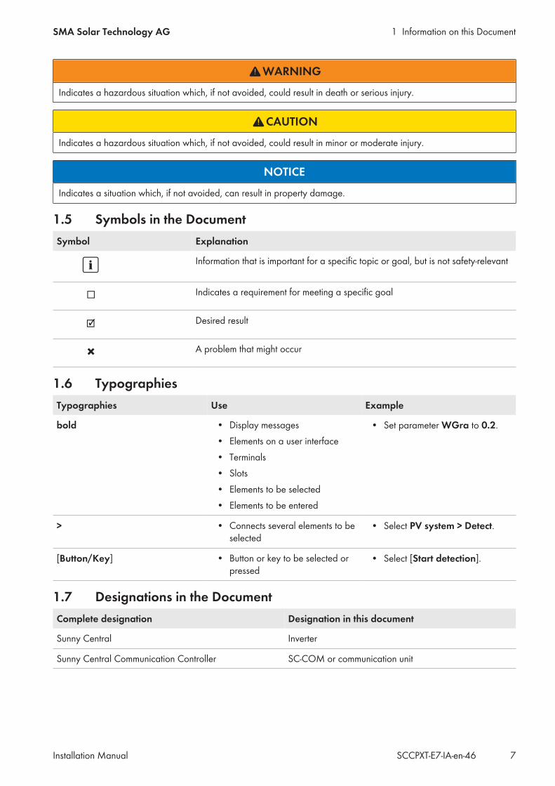
1.4 Levels of warning messagesThe following levels of warning messages may occur when handling the product.
DANGER
Indicates a hazardous situation which, if not avoided, will result in death or serious injury.
1 Information on this DocumentSMA Solar Technology AG
Installation Manual 7SCCPXT-E7-IA-en-46
WARNING
Indicates a hazardous situation which, if not avoided, could result in death or serious injury.
CAUTION
Indicates a hazardous situation which, if not avoided, could result in minor or moderate injury.
NOTICE
Indicates a situation which, if not avoided, can result in property damage.
1.5 Symbols in the DocumentSymbol Explanation
Information that is important for a specific topic or goal, but is not safety-relevant
Indicates a requirement for meeting a specific goal
Desired result
A problem that might occur
1.6 TypographiesTypographies Use Example
bold • Display messages• Elements on a user interface• Terminals• Slots• Elements to be selected• Elements to be entered
• Set parameter WGra to 0.2.
> • Connects several elements to beselected
• Select PV system > Detect.
[Button/Key] • Button or key to be selected orpressed
• Select [Start detection].
1.7 Designations in the DocumentComplete designation Designation in this document
Sunny Central Inverter
Sunny Central Communication Controller SC-COM or communication unit
2 Safety SMA Solar Technology AG
Installation ManualSCCPXT-E7-IA-en-468
2 Safety2.1 Intended UseThe Sunny Central is a PV inverter which converts the direct current generated in the PV modules into grid-compliantalternating current. An external MV transformer fitted downstream feeds the generated alternating current into theutility grid.The product is suitable for indoor and outdoor use.The enclosure complies with degree of protection IP54. The inverter is classified under Class 4C2 as perEN 60721-3-4 and is suitable for operation in a chemically active environment.The maximum permissible DC input voltage of the inverter must not be exceeded.The inverter must only be operated in conjunction with a suitable MV transformer.
• The MV transformer must be designed for voltages that arise during pulsed mode of the inverter.• For the Sunny Central 500CP XT/630CP XT/720CP XT/760CP XT/800CP XT the maximum voltage to ground is:
±1,450 V• For the Sunny Central 850CP XT/900CP XT/1000CP XT the maximum voltage to ground is: ±1,600 V• Do not connect more than one inverter to one winding of the MV transformer.• The neutral conductor on the low-voltage side of the MV transformer must not be grounded.
You can find further information on suitable transformers in the technical information "Requirements for Medium-Voltage Transformers and Transformers for Internal Power Supply for the SUNNY CENTRAL".Do not deactivate or modify settings that affect grid management services without first obtaining approval from the gridoperator.Use this product only in accordance with the information provided in the enclosed documentation and with the locallyapplicable standards and directives. Any other application may cause personal injury or property damage.Alterations to the product, e.g. changes or modifications, are only permitted with the express written permission ofSMA Solar Technology AG. Unauthorized alterations will void guarantee and warranty claims and in most casesterminate the operating license. SMA Solar Technology AG shall not be held liable for any damage caused by suchchanges.Any use of the product other than that described in the Intended Use section does not qualify as the intended use.The enclosed documentation is an integral part of this product. Keep the documentation in a convenient place forfuture reference and observe all instructions contained therein.All work on the product must only be performed using appropriate tools and in compliance with the ESD protectionregulations.Suitable personal protective equipment must be worn by all persons working on or with the product.Unauthorized persons must not operate the product and must be kept at a safe distance from the product.The product must not be operated with open covers or doors.The product must not be opened when it is raining or when humidity exceeds 95%.The product must not be operated with any technical defects.The type label must remain permanently attached to the product.
2 SafetySMA Solar Technology AG
Installation Manual 9SCCPXT-E7-IA-en-46
2.2 Safety InformationThis section contains safety information that must be observed at all times when working on or with the product. Toprevent personal injury and property damage and to ensure long-term operation of the product, read this sectioncarefully and observe all safety information at all times.
DANGER
Danger to life from electric shock due to live voltageHigh voltages are present in the live components of the product. Touching live components results in death orserious injury due to electric shock.
• Wear suitable personal protective equipment for all work on the product.• Do not touch any live components.• Observe all warning messages on the product and in the documentation.• Observe all safety information of the module manufacturer.• After switching off the inverter, wait at least 15 minutes before opening it to allow the capacitors to discharge
completely (see Section 6.2, page 37).
DANGER
Danger to life from electric shock due to live DC cablesDC cables connected to PV modules that are exposed to sunlight carry live voltage. Touching live cables results indeath or serious injury due to electric shock.
• Prior to connecting the DC cables, ensure that the DC cables are voltage-free.• Wear suitable personal protective equipment for all work on the device.
DANGER
Danger to life from electric shock due to ground faultIf a ground fault has occurred, parts of the PV power plant that are supposedly grounded may in fact be live.Touching incorrectly grounded parts of the PV power plant results in death or serious injuries from electric shock.
• Before working on the PV power plant, ensure that no ground fault is present.• Wear suitable personal protective equipment for all work on the device.
DANGER
Danger to life from electric shock due to damaged productOperating a damaged product can lead to hazardous situations that result in death or serious injuries due toelectric shock.
• Only operate the product when it is in a flawless technical condition and safe to operate.• Check the product regularly for visible damage.• Make sure that all external safety equipment is freely accessible at all times.• Make sure that all safety equipment is in good working order.• Wear suitable personal protective equipment for all work on the product.
2 Safety SMA Solar Technology AG
Installation ManualSCCPXT-E7-IA-en-4610
DANGER
Danger to life from electric shock even if the inverter is disconnected on the AC and DC sidesThe precharge unit of the order option "Q at Night" will carry live voltage even if the AC disconnection unit and theDC switchgear are open. Touching live components results in death or serious injury due to electric shock.
• Do not touch any live components.• Switch off the inverter.• After switching off the inverter, wait at least 15 minutes before opening it to allow the capacitors to discharge
completely.• Ensure that no voltage is present.• Do not remove protective covers.• Observe the warning messages.• Wear suitable personal protective equipment for all work on the product.
WARNING
Danger to life from electric shock when entering the PV fieldGround-fault monitoring does not provide protection from personal injury. PV modules which are grounded withground-fault monitoring discharge voltage to ground. Entering the PV field can result in lethal electric shocks.
• Ensure that the insulation resistance of the PV field exceeds the minimum value. The minimum value of theinsulation resistance is: 1 kΩ.
• Before entering the PV field, switch the PV modules to insulated operation.• Configure the PV power plant as a closed electrical operating area.
WARNING
Danger to life from electric shock if the product is not lockedIf the product is not locked, unauthorized persons will have access to live components carrying lethal voltages.Touching live components can result in death or serious injury due to electric shock.
• Always close and lock the product.• Remove the keys.• Store the keys in a safe place.• Ensure that no unauthorized persons have access to the closed electrical operating area.
WARNING
Danger to life due to blocked escape routesIn hazardous situations, blocked escape routes can lead to death or serious injury. Opening the doors of twoproducts located opposite each other can block the escape route. It is imperative that the escape route is freelyaccessible at all times.
• An escape route must be available at all times. Make sure the minimum passage width of the escape routemeets local standards.
• Do not place any objects in the escape route area.• Remove all tripping hazards from escape routes.
2 SafetySMA Solar Technology AG
Installation Manual 11SCCPXT-E7-IA-en-46
CAUTION
Risk of burns due to hot componentsSome components of the product can get very hot during operation. Touching these components can cause burns.
• Observe the warnings on all components.• During operation, do not touch any components marked with such warnings.• After switching off the product, wait until any hot components have cooled down sufficiently.• Wear suitable personal protective equipment for all work on the product.
NOTICE
Property damage due to dust intrusion and moisture penetrationDust or moisture intrusion can damage the product and impair its functionality.
• Do not open the enclosure during rainfall or when humidity exceeds the specified thresholds. The humiditythresholds are: 15% to 95%.
• Only perform maintenance work when the environment is dry and free of dust.• Operation of the product is only permitted when it is closed.• Connect the external supply voltage after mounting and installing the product.• If the installation or commissioning process is interrupted, mount all panels.• Close and lock the enclosure.• The product must always be closed for storage.• Store the product in a dry and covered location.• Temperature at the storage location must be in the specified range. The temperature range is:
−25°C to +70°C.
NOTICE
Damage to electronic components due to electrostatic dischargeElectrostatic discharge can damage or destroy electronic components.
• Observe the ESD safety regulations when working on the product.• Wear suitable personal protective equipment for all work on the product.• Discharge electrostatic charge by touching grounded enclosure parts or other grounded elements. Only then is
it safe to touch electronic components.
2.3 Personal Protective EquipmentAlways wear suitable protective equipmentWhen working on the product, always wear the appropriate personal protective equipment for the specific job.
The following personal protective equipment is regarded to be the minimum requirement: In a dry environment, safety shoes of category S3 with perforation-proof soles and steel toe caps During precipitation or on moist ground, safety boots of category S5 with perforation-proof soles and steel toe
caps Tight-fitting work clothes made of 100% cotton Suitable work pants
2 Safety SMA Solar Technology AG
Installation ManualSCCPXT-E7-IA-en-4612
Individually fitted hearing protection Safety gloves
Any other prescribed protective equipment must also be used.
3 Product OverviewSMA Solar Technology AG
Installation Manual 13SCCPXT-E7-IA-en-46
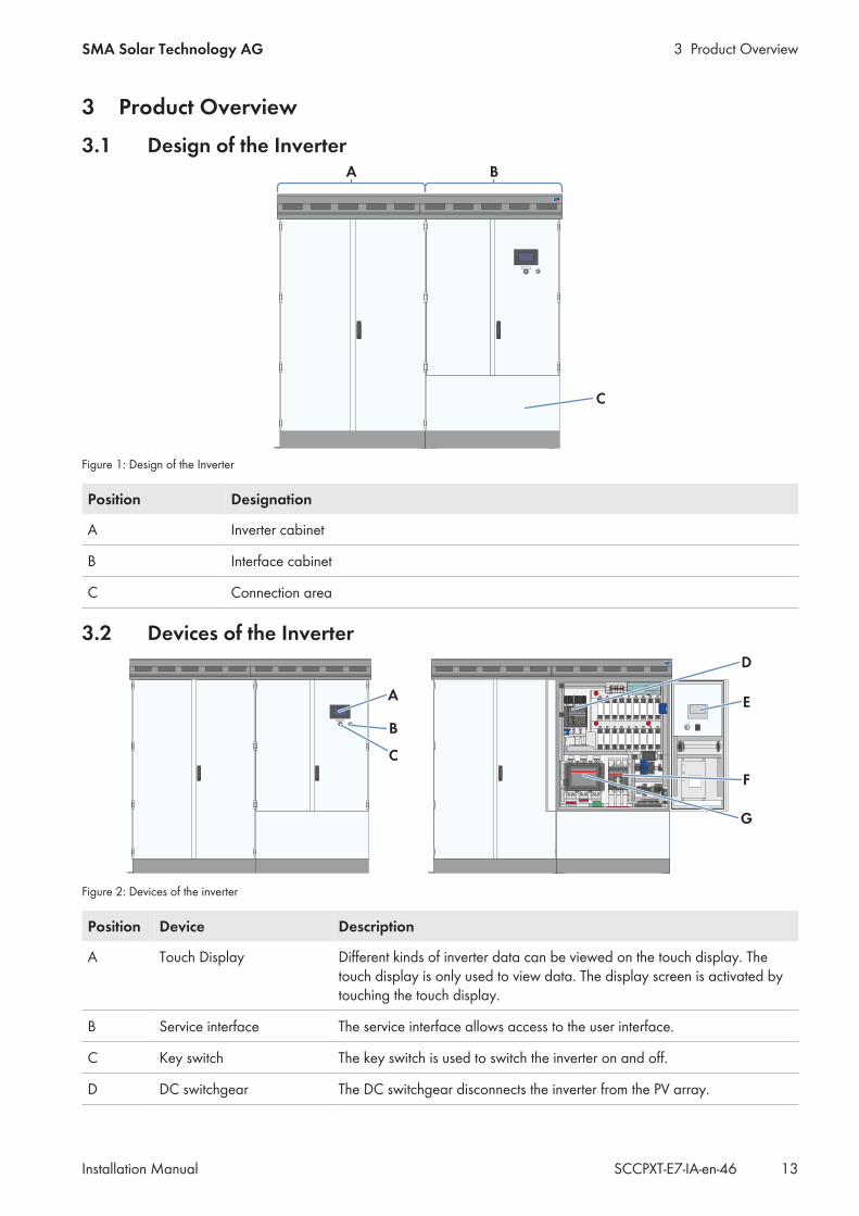
3 Product Overview3.1 Design of the Inverter
A
C
B
Figure 1: Design of the Inverter
Position Designation
A Inverter cabinet
B Interface cabinet
C Connection area
3.2 Devices of the Inverter
A
B
D
E
F
C
G
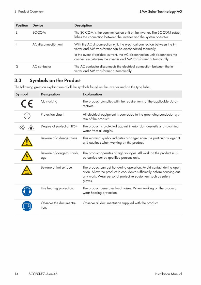
Figure 2: Devices of the inverter
Position Device Description
A Touch Display Different kinds of inverter data can be viewed on the touch display. Thetouch display is only used to view data. The display screen is activated bytouching the touch display.
B Service interface The service interface allows access to the user interface.
C Key switch The key switch is used to switch the inverter on and off.
D DC switchgear The DC switchgear disconnects the inverter from the PV array.
3 Product Overview SMA Solar Technology AG
Installation ManualSCCPXT-E7-IA-en-4614
Position Device Description
E SC-COM The SC-COM is the communication unit of the inverter. The SC-COM estab-lishes the connection between the inverter and the system operator.
F AC disconnection unit With the AC disconnection unit, the electrical connection between the in-verter and MV transformer can be disconnected manually.In the event of residual current, the AC disconnection unit disconnects theconnection between the inverter and MV transformer automatically.
G AC contactor The AC contactor disconnects the electrical connection between the in-verter and MV transformer automatically.
3.3 Symbols on the ProductThe following gives an explanation of all the symbols found on the inverter and on the type label.
Symbol Designation Explanation
CE marking The product complies with the requirements of the applicable EU di-rectives.
Protection class I All electrical equipment is connected to the grounding conductor sys-tem of the product.
Degree of protection IP54 The product is protected against interior dust deposits and splashingwater from all angles.
Beware of a danger zone This warning symbol indicates a danger zone. Be particularly vigilantand cautious when working on the product.
Beware of dangerous volt-age
The product operates at high voltages. All work on the product mustbe carried out by qualified persons only.
Beware of hot surface The product can get hot during operation. Avoid contact during oper-ation. Allow the product to cool down sufficiently before carrying outany work. Wear personal protective equipment such as safetygloves.
Use hearing protection. The product generates loud noises. When working on the product,wear hearing protection.
Observe the documenta-tion.
Observe all documentation supplied with the product.
4 Transport and MountingSMA Solar Technology AG
Installation Manual 15SCCPXT-E7-IA-en-46
4 Transport and Mounting4.1 Safety during Transport and Mounting
WARNING
Danger of crushing if raised or suspended loads tip over, fall or swayVibrations or careless or hasty lifting and transportation may cause the product to tip over or fall. This can result indeath or serious injury.
• All national standards and provisions for transport must be respected.• Always transport the product as close to the floor as possible.• Use all suspension points for transportation.• Avoid fast or jerky movements during transport.• Always maintain a sufficient safety distance from the product during transport.• All means of transport and auxiliary equipment used must be designed for the weight of the product. Weight:
1,900 kg.• Wear suitable personal protective equipment for all work on the product.• Disassemble the kick plates when transporting the inverter with a forklift, pallet truck or crane fork. Thus, the
contact surface of the product on the forks is sufficiently extended (see Section 7.2.1, page 41).
NOTICE
Damage to the frame construction of the inverter due to uneven support surfacePlacing the inverter on uneven surfaces can cause buckling so that the inverter doors will no longer close properly.This may lead to moisture and dust penetration into the inverter.
• Never place the inverter on an unstable, uneven surface even for a short period of time.• The unevenness of the support surface must be less than 0.25%.• The support surface must be suitable to take the weight of the inverter. Weight: 1,900 kg.• Do not transport the inverter with mounted kick plates.
4.2 Requirements for Transport and Mounting
4.2.1 Requirements and Ambient Conditions The requirements for the mounting location must be met (see Section 9.1.1, page 69). The requirements for the support surface must be met (see Section 9.1.2, page 70). The requirements for the foundation and cable arrangement must be met (see Section 9.1.3, page 70). Minimum clearances must be observed (see Section 9.1.6, page 74).
4 Transport and Mounting SMA Solar Technology AG
Installation ManualSCCPXT-E7-IA-en-4616
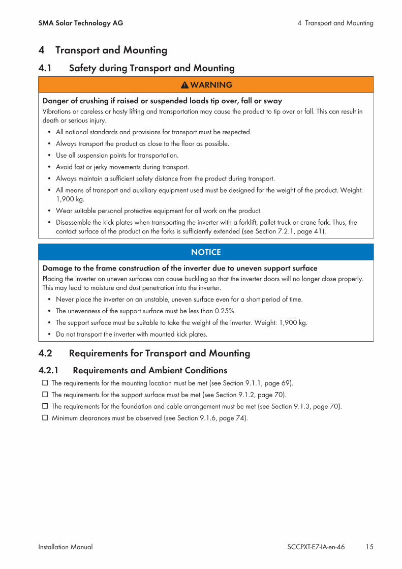
4.2.2 Center of Gravity Marker on the InverterThe center of gravity of the inverter is not in the middle of the device. Take this into account during transport. The centerof gravity of the inverter is marked on the packaging and on the enclosure with the center of gravity symbol.
Figure 3: Center of gravity symbol
4.2.3 Preparation for Mounting
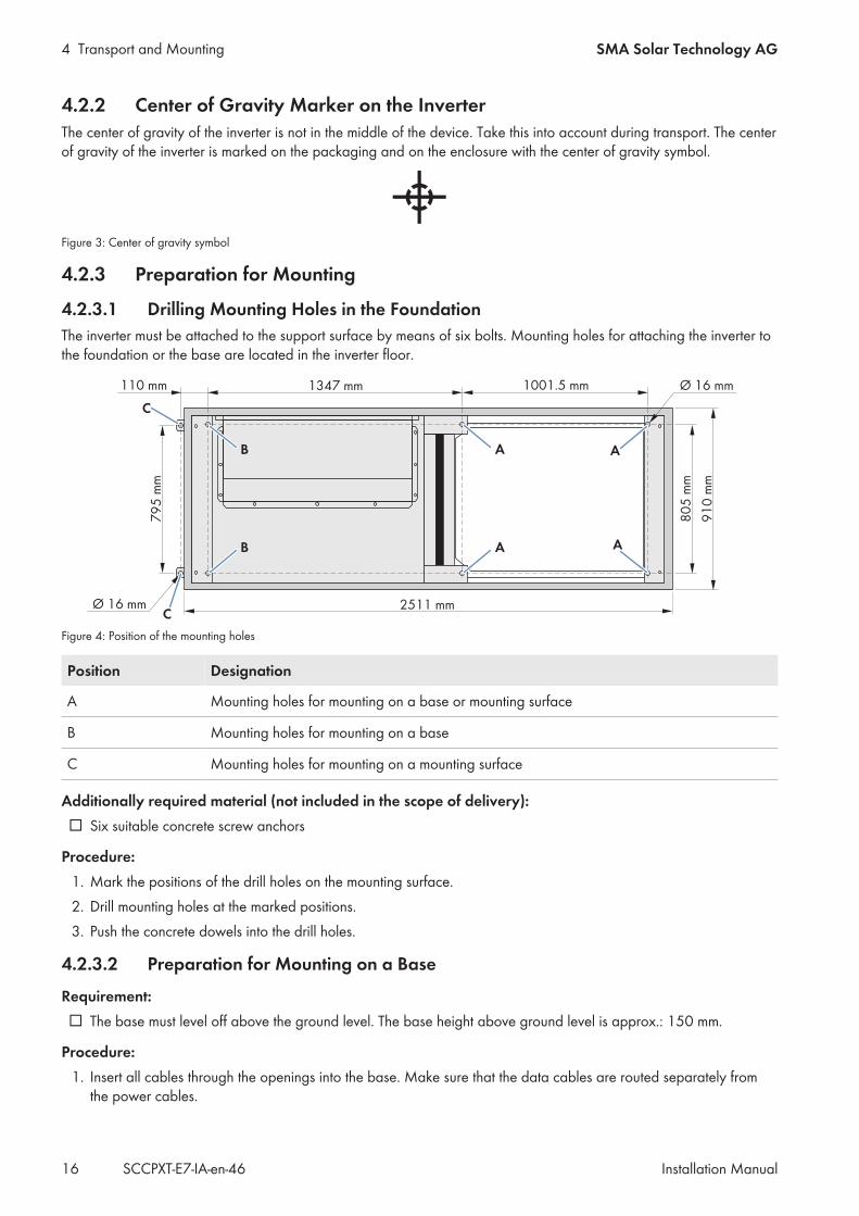
4.2.3.1 Drilling Mounting Holes in the FoundationThe inverter must be attached to the support surface by means of six bolts. Mounting holes for attaching the inverter tothe foundation or the base are located in the inverter floor.
Figure 4: Position of the mounting holes
Position Designation
A Mounting holes for mounting on a base or mounting surface
B Mounting holes for mounting on a base
C Mounting holes for mounting on a mounting surface
Additionally required material (not included in the scope of delivery): Six suitable concrete screw anchors
Procedure:1. Mark the positions of the drill holes on the mounting surface.2. Drill mounting holes at the marked positions.3. Push the concrete dowels into the drill holes.
4.2.3.2 Preparation for Mounting on a Base
Requirement: The base must level off above the ground level. The base height above ground level is approx.: 150 mm.
Procedure:1. Insert all cables through the openings into the base. Make sure that the data cables are routed separately from
the power cables.
4 Transport and MountingSMA Solar Technology AG
Installation Manual 17SCCPXT-E7-IA-en-46
2. Seal the opening, e.g. with expanding foam. This will prevent living creatures from getting into the inverter.3. Fill up the excavation pit and level off to ground level.
4.3 Transporting the Inverter
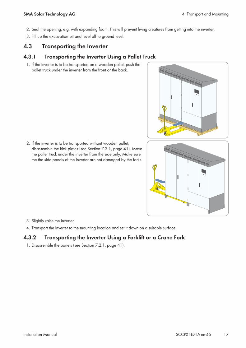
4.3.1 Transporting the Inverter Using a Pallet Truck1. If the inverter is to be transported on a wooden pallet, push the
pallet truck under the inverter from the front or the back.
2. If the inverter is to be transported without wooden pallet,disassemble the kick plates (see Section 7.2.1, page 41). Movethe pallet truck under the inverter from the side only. Make surethe the side panels of the inverter are not damaged by the forks.
3. Slightly raise the inverter.4. Transport the inverter to the mounting location and set it down on a suitable surface.
4.3.2 Transporting the Inverter Using a Forklift or a Crane Fork1. Disassemble the panels (see Section 7.2.1, page 41).
4 Transport and Mounting SMA Solar Technology AG
Installation ManualSCCPXT-E7-IA-en-4618
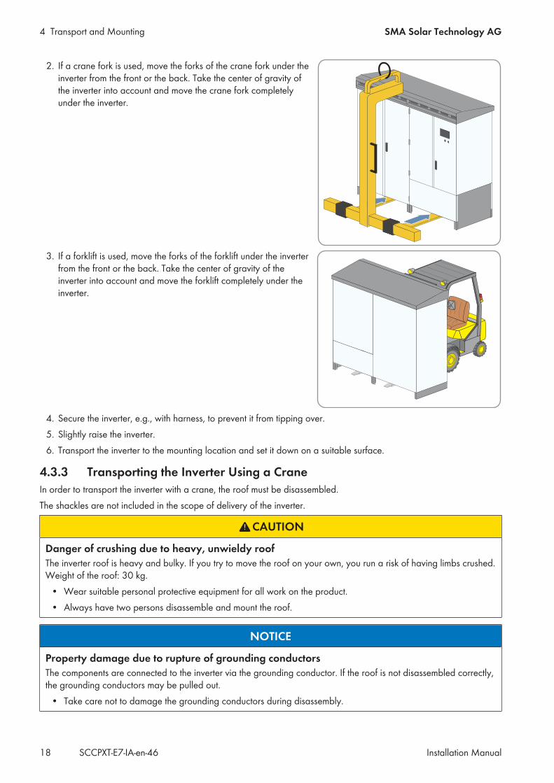
2. If a crane fork is used, move the forks of the crane fork under theinverter from the front or the back. Take the center of gravity ofthe inverter into account and move the crane fork completelyunder the inverter.
3. If a forklift is used, move the forks of the forklift under the inverterfrom the front or the back. Take the center of gravity of theinverter into account and move the forklift completely under theinverter.
4. Secure the inverter, e.g., with harness, to prevent it from tipping over.5. Slightly raise the inverter.6. Transport the inverter to the mounting location and set it down on a suitable surface.
4.3.3 Transporting the Inverter Using a CraneIn order to transport the inverter with a crane, the roof must be disassembled.The shackles are not included in the scope of delivery of the inverter.
CAUTION
Danger of crushing due to heavy, unwieldy roofThe inverter roof is heavy and bulky. If you try to move the roof on your own, you run a risk of having limbs crushed.Weight of the roof: 30 kg.
• Wear suitable personal protective equipment for all work on the product.• Always have two persons disassemble and mount the roof.
NOTICE
Property damage due to rupture of grounding conductorsThe components are connected to the inverter via the grounding conductor. If the roof is not disassembled correctly,the grounding conductors may be pulled out.
• Take care not to damage the grounding conductors during disassembly.
4 Transport and MountingSMA Solar Technology AG
Installation Manual 19SCCPXT-E7-IA-en-46
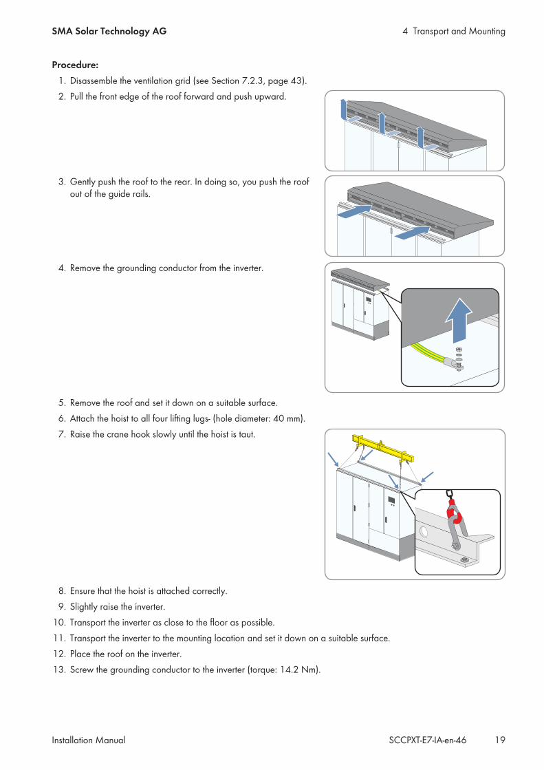
Procedure:1. Disassemble the ventilation grid (see Section 7.2.3, page 43).2. Pull the front edge of the roof forward and push upward.
3. Gently push the roof to the rear. In doing so, you push the roofout of the guide rails.
4. Remove the grounding conductor from the inverter.
5. Remove the roof and set it down on a suitable surface.6. Attach the hoist to all four lifting lugs- (hole diameter: 40 mm).7. Raise the crane hook slowly until the hoist is taut.
8. Ensure that the hoist is attached correctly.9. Slightly raise the inverter.
10. Transport the inverter as close to the floor as possible.11. Transport the inverter to the mounting location and set it down on a suitable surface.12. Place the roof on the inverter.13. Screw the grounding conductor to the inverter (torque: 14.2 Nm).
4 Transport and Mounting SMA Solar Technology AG
Installation ManualSCCPXT-E7-IA-en-4620
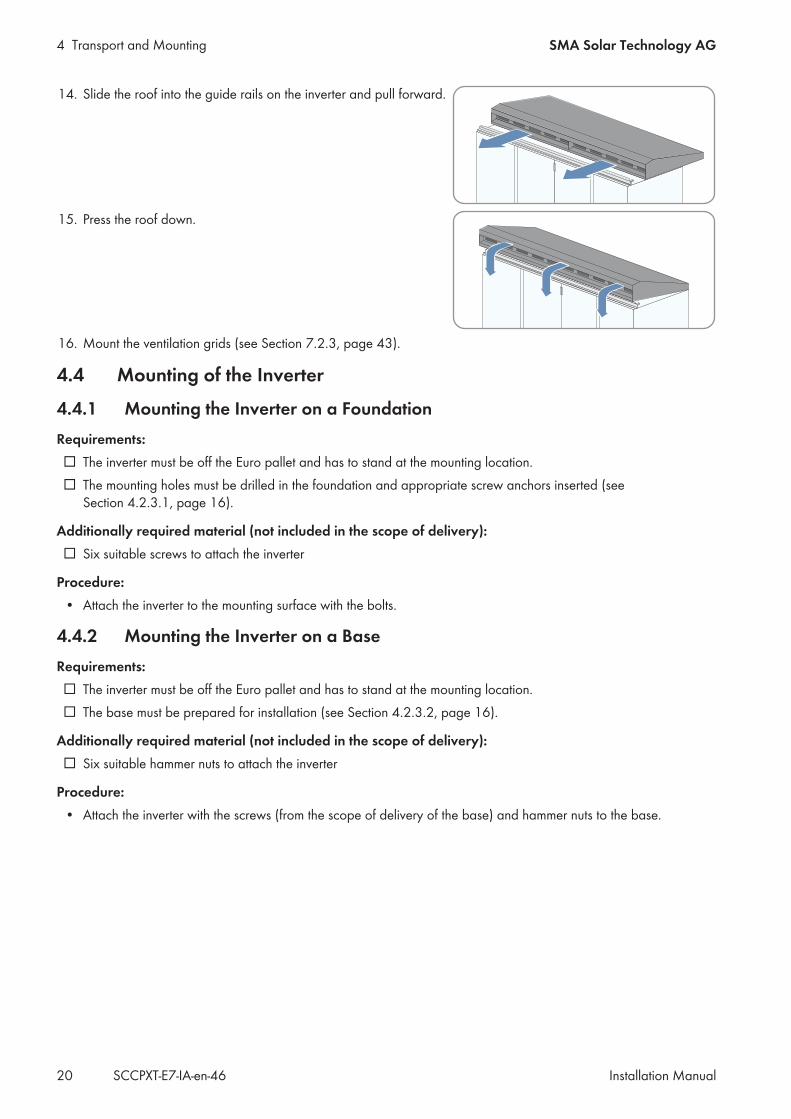
14. Slide the roof into the guide rails on the inverter and pull forward.
15. Press the roof down.
16. Mount the ventilation grids (see Section 7.2.3, page 43).
4.4 Mounting of the Inverter
4.4.1 Mounting the Inverter on a FoundationRequirements: The inverter must be off the Euro pallet and has to stand at the mounting location. The mounting holes must be drilled in the foundation and appropriate screw anchors inserted (see
Section 4.2.3.1, page 16).
Additionally required material (not included in the scope of delivery): Six suitable screws to attach the inverter
Procedure:• Attach the inverter to the mounting surface with the bolts.
4.4.2 Mounting the Inverter on a BaseRequirements: The inverter must be off the Euro pallet and has to stand at the mounting location. The base must be prepared for installation (see Section 4.2.3.2, page 16).
Additionally required material (not included in the scope of delivery): Six suitable hammer nuts to attach the inverter
Procedure:• Attach the inverter with the screws (from the scope of delivery of the base) and hammer nuts to the base.
5 InstallationSMA Solar Technology AG
Installation Manual 21SCCPXT-E7-IA-en-46
5 Installation5.1 Safety during Installation
DANGER
Danger to life from electric shock due to live voltageHigh voltages are present in the live components of the product. Touching live components results in death orserious injury due to electric shock.
• Wear suitable personal protective equipment for all work on the product.• Do not touch any live components.• Observe all warning messages on the product and in the documentation.• Observe all safety information of the module manufacturer.• After switching off the inverter, wait at least 15 minutes before opening it to allow the capacitors to discharge
completely (see Section 6.2, page 37).
DANGER
Danger to life from electric shock due to live DC cablesDC cables connected to PV modules that are exposed to sunlight carry live voltage. Touching live cables results indeath or serious injury due to electric shock.
• Prior to connecting the DC cables, ensure that the DC cables are voltage-free.• Wear suitable personal protective equipment for all work on the device.
DANGER
Danger to life from electric shock due to ground faultIf a ground fault has occurred, parts of the PV power plant that are supposedly grounded may in fact be live.Touching incorrectly grounded parts of the PV power plant results in death or serious injuries from electric shock.
• Before working on the PV power plant, ensure that no ground fault is present.• Wear suitable personal protective equipment for all work on the device.
WARNING
Danger to life from electric shock when entering the PV fieldGround-fault monitoring does not provide protection from personal injury. PV modules which are grounded withground-fault monitoring discharge voltage to ground. Entering the PV field can result in lethal electric shocks.
• Ensure that the insulation resistance of the PV field exceeds the minimum value. The minimum value of theinsulation resistance is: 1 kΩ.
• Before entering the PV field, switch the PV modules to insulated operation.• Configure the PV power plant as a closed electrical operating area.
5 Installation SMA Solar Technology AG
Installation ManualSCCPXT-E7-IA-en-4622
WARNING
Danger to life due to arc fault caused by damaged connection busbarsIf excessive force is exerted while connecting the cables, the connection busbars can be bent or damaged. This willlead to reduced clearances and creepage distances. Reduced clearances and creepage distances can lead to arcfaults.
• Cut the cables to the correct length and prepare them for connection.• Position the terminal lugs on the connection busbars ensuring a large contact surface.• Tighten to the specified torque.
DC-side disconnectionThe DC main distributions and DC subdistributions should be equipped with load-break switches or circuitbreakers. Load-break switches or circuit breakers enable trouble-free DC-side disconnection of the inverter.
5.2 Preparing the Installation
5.2.1 Replacing the Desiccant Bag in the InverterDesiccant bag in the inverter cabinetThe desiccant bag in the inverter cabinet protects the electronic components from moisture. The desiccant bagmust be replaced by a new desiccant bag included in the scope of delivery one day before commissioning.
Procedure:1. Remove and dispose of the desiccant bag located under the inverter bridges.2. Remove the desiccant bag included in the scope of delivery from the foil and position it under the inverter bridges.
5.2.2 Mounting the Ventilation PlateThe guide rails for the ventilation plate are located in the floor area of the inverter cabinet.
Procedure:• Slide the ventilation plate into the guide rails in the inverter cabinet. The ventilation grid in the ventilation plate
should be facing the rear panel. The ventilation plate is flush with the inverter. The ventilation plate will not go all the way in?
• Grip the ventilation plate from underneath and press the middle part upwards while sliding it in.
5 InstallationSMA Solar Technology AG
Installation Manual 23SCCPXT-E7-IA-en-46
5.3 Installing the Grounding
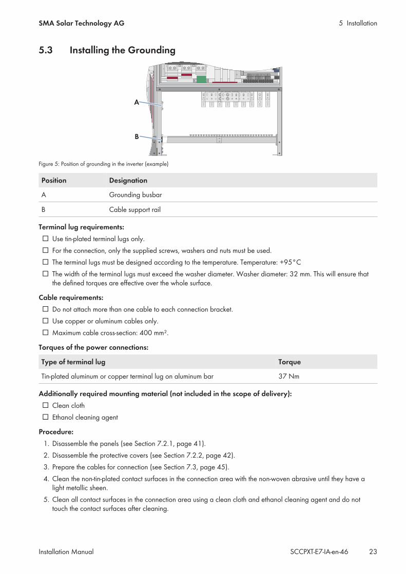
Figure 5: Position of grounding in the inverter (example)
Position Designation
A Grounding busbar
B Cable support rail
Terminal lug requirements: Use tin-plated terminal lugs only. For the connection, only the supplied screws, washers and nuts must be used. The terminal lugs must be designed according to the temperature. Temperature: +95°C The width of the terminal lugs must exceed the washer diameter. Washer diameter: 32 mm. This will ensure that
the defined torques are effective over the whole surface.
Cable requirements: Do not attach more than one cable to each connection bracket. Use copper or aluminum cables only. Maximum cable cross-section: 400 mm².
Torques of the power connections:
Type of terminal lug Torque
Tin-plated aluminum or copper terminal lug on aluminum bar 37 Nm
Additionally required mounting material (not included in the scope of delivery): Clean cloth Ethanol cleaning agent
Procedure:1. Disassemble the panels (see Section 7.2.1, page 41).2. Disassemble the protective covers (see Section 7.2.2, page 42).3. Prepare the cables for connection (see Section 7.3, page 45).4. Clean the non-tin-plated contact surfaces in the connection area with the non-woven abrasive until they have a
light metallic sheen.5. Clean all contact surfaces in the connection area using a clean cloth and ethanol cleaning agent and do not
touch the contact surfaces after cleaning.
5 Installation SMA Solar Technology AG
Installation ManualSCCPXT-E7-IA-en-4624
6. Connect the cables in accordance with the circuit diagram. Only use the screws, nuts and washers included in thescope of delivery and make sure that the screw heads always point forwards.
7. Secure the cables on the cable support rail. This will prevent the cable from being pulled out inadvertently.8. Mount the protective covers (see Section 7.2.2, page 42).9. Mount the panels (see Section 7.2.1, page 41).
5.4 Installing the DC Connection
5.4.1 Connecting the DC Cable to the Busbar
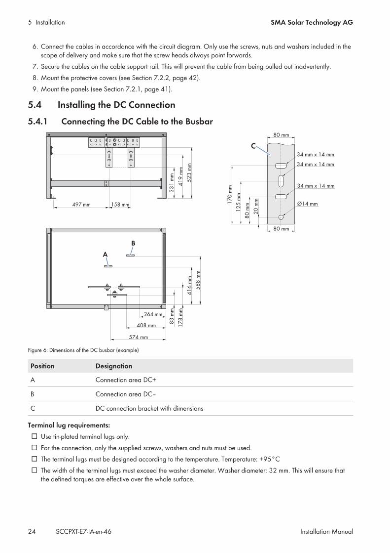
Figure 6: Dimensions of the DC busbar (example)
Position Designation
A Connection area DC+
B Connection area DC‒
C DC connection bracket with dimensions
Terminal lug requirements: Use tin-plated terminal lugs only. For the connection, only the supplied screws, washers and nuts must be used. The terminal lugs must be designed according to the temperature. Temperature: +95°C The width of the terminal lugs must exceed the washer diameter. Washer diameter: 32 mm. This will ensure that
the defined torques are effective over the whole surface.
5 InstallationSMA Solar Technology AG
Installation Manual 25SCCPXT-E7-IA-en-46
Cable requirements: The DC cables must be designed for the maximum PV voltage and must have double or reinforced insulation. No more than two cables must be connected to each DC terminal. Use copper or aluminum cables only. Maximum cable cross-section: 400 mm². Terminal lugs: M12
Torques of the power connections:
Type of terminal lug Torque
Tin-plated aluminum terminal lug on copper bar 37 Nm
Tin-plated copper terminal lug on copper bar 60 Nm
Additionally required mounting material (not included in the scope of delivery): Clean cloth Ethanol cleaning agent
Procedure:1. Disassemble the panels (see Section 7.2.1, page 41).2. Disassemble the protective covers (see Section 7.2.2, page 42).3. Prepare the cables for connection (see Section 7.3, page 45).4. Clean the non-tin-plated contact surfaces in the connection area with the non-woven abrasive until they have a
light metallic sheen.5. Clean all contact surfaces in the connection area using a clean cloth and ethanol cleaning agent and do not
touch the contact surfaces after cleaning.6. Connect the cables in accordance with the circuit diagram. Only use the screws, nuts and washers included in the
scope of delivery and make sure that the screw heads always point forwards.7. Secure the cables on the cable support rail. This will prevent the cable from being pulled out inadvertently.8. Mount the protective covers (see Section 7.2.2, page 42).9. Mount the panels (see Section 7.2.1, page 41).
5 Installation SMA Solar Technology AG
Installation ManualSCCPXT-E7-IA-en-4626
5.4.2 Connecting the DC Cables to the Connection Brackets
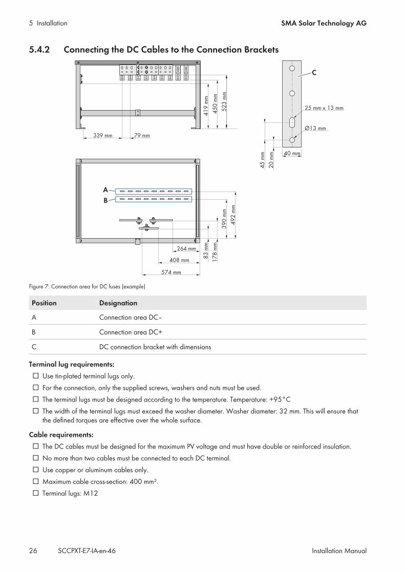
Figure 7: Connection area for DC fuses (example)
Position Designation
A Connection area DC‒
B Connection area DC+
C DC connection bracket with dimensions
Terminal lug requirements: Use tin-plated terminal lugs only. For the connection, only the supplied screws, washers and nuts must be used. The terminal lugs must be designed according to the temperature. Temperature: +95°C The width of the terminal lugs must exceed the washer diameter. Washer diameter: 32 mm. This will ensure that
the defined torques are effective over the whole surface.
Cable requirements: The DC cables must be designed for the maximum PV voltage and must have double or reinforced insulation. No more than two cables must be connected to each DC terminal. Use copper or aluminum cables only. Maximum cable cross-section: 400 mm². Terminal lugs: M12
5 InstallationSMA Solar Technology AG
Installation Manual 27SCCPXT-E7-IA-en-46
Torques of the power connections:
Type of terminal lug Torque
Tin-plated aluminum or copper terminal lug on aluminum bar 37 Nm
Additionally required mounting material (not included in the scope of delivery): Clean cloth Ethanol cleaning agent
Requirement: The reduction of DC input currents must be complied with (see Section 9.3.2, page 79).
Procedure:1. Disassemble the panels (see Section 7.2.1, page 41).2. Disassemble the protective covers (see Section 7.2.2, page 42).3. Prepare the cables for connection (see Section 7.3, page 45).4. Clean the non-tin-plated contact surfaces in the connection area with the non-woven abrasive until they have a
light metallic sheen.5. Clean all contact surfaces in the connection area using a clean cloth and ethanol cleaning agent and do not
touch the contact surfaces after cleaning.6. Connect the cables in accordance with the circuit diagram. Only use the screws, nuts and washers included in the
scope of delivery and make sure that the screw heads always point forwards.7. Secure the cables on the cable support rail. This will prevent the cable from being pulled out inadvertently.8. Mount the protective covers (see Section 7.2.2, page 42).9. Mount the panels (see Section 7.2.1, page 41).
5.5 Installing the AC Connection
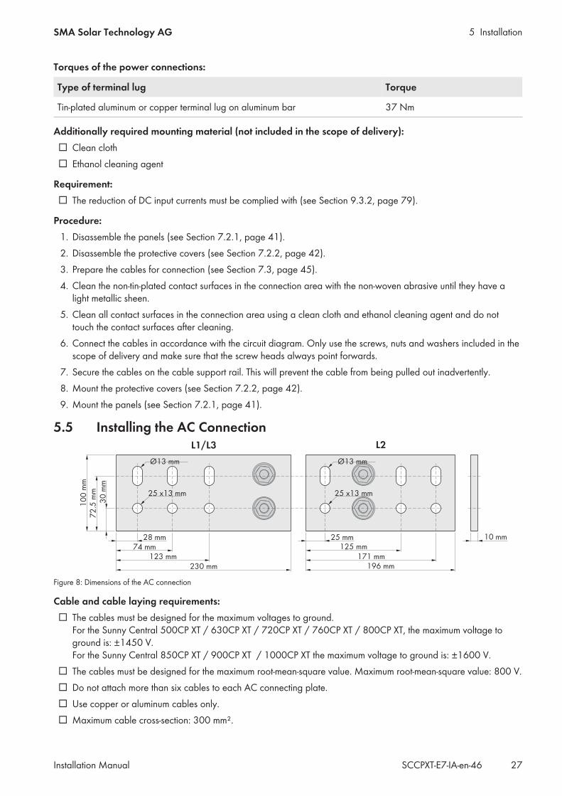
Figure 8: Dimensions of the AC connection
Cable and cable laying requirements: The cables must be designed for the maximum voltages to ground.
For the Sunny Central 500CP XT / 630CP XT / 720CP XT / 760CP XT / 800CP XT, the maximum voltage toground is: ±1450 V. For the Sunny Central 850CP XT / 900CP XT / 1000CP XT the maximum voltage to ground is: ±1600 V.
The cables must be designed for the maximum root-mean-square value. Maximum root-mean-square value: 800 V. Do not attach more than six cables to each AC connecting plate. Use copper or aluminum cables only. Maximum cable cross-section: 300 mm².
5 Installation SMA Solar Technology AG
Installation ManualSCCPXT-E7-IA-en-4628
All line conductor cables must be of the same length and must not exceed the maximum cable length. Themaximum cable length is 15 m.
The AC cables must be bundled in the three-phase system. Between the MV transformer and the inverter, three separate cable routes for the AC cables must be available,
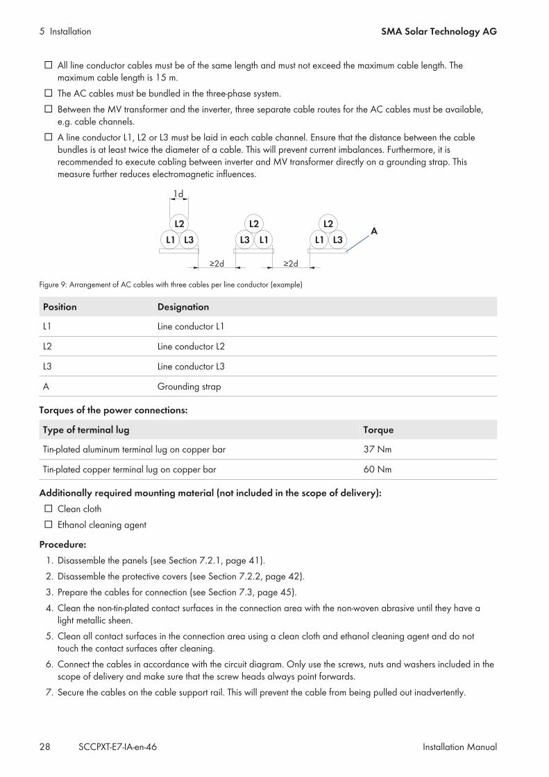
e.g. cable channels. A line conductor L1, L2 or L3 must be laid in each cable channel. Ensure that the distance between the cable
bundles is at least twice the diameter of a cable. This will prevent current imbalances. Furthermore, it isrecommended to execute cabling between inverter and MV transformer directly on a grounding strap. Thismeasure further reduces electromagnetic influences.
Figure 9: Arrangement of AC cables with three cables per line conductor (example)
Position Designation
L1 Line conductor L1
L2 Line conductor L2
L3 Line conductor L3
A Grounding strap
Torques of the power connections:
Type of terminal lug Torque
Tin-plated aluminum terminal lug on copper bar 37 Nm
Tin-plated copper terminal lug on copper bar 60 Nm
Additionally required mounting material (not included in the scope of delivery): Clean cloth Ethanol cleaning agent
Procedure:1. Disassemble the panels (see Section 7.2.1, page 41).2. Disassemble the protective covers (see Section 7.2.2, page 42).3. Prepare the cables for connection (see Section 7.3, page 45).4. Clean the non-tin-plated contact surfaces in the connection area with the non-woven abrasive until they have a
light metallic sheen.5. Clean all contact surfaces in the connection area using a clean cloth and ethanol cleaning agent and do not
touch the contact surfaces after cleaning.6. Connect the cables in accordance with the circuit diagram. Only use the screws, nuts and washers included in the
scope of delivery and make sure that the screw heads always point forwards.7. Secure the cables on the cable support rail. This will prevent the cable from being pulled out inadvertently.
5 InstallationSMA Solar Technology AG
Installation Manual 29SCCPXT-E7-IA-en-46
8. Mount the protective covers (see Section 7.2.2, page 42).9. Mount the panels (see Section 7.2.1, page 41).
5.6 Connecting the Cables for Communication, Control, Supply Voltageand Monitoring
5.6.1 Connecting Optical Fibers with Subscriber Connector
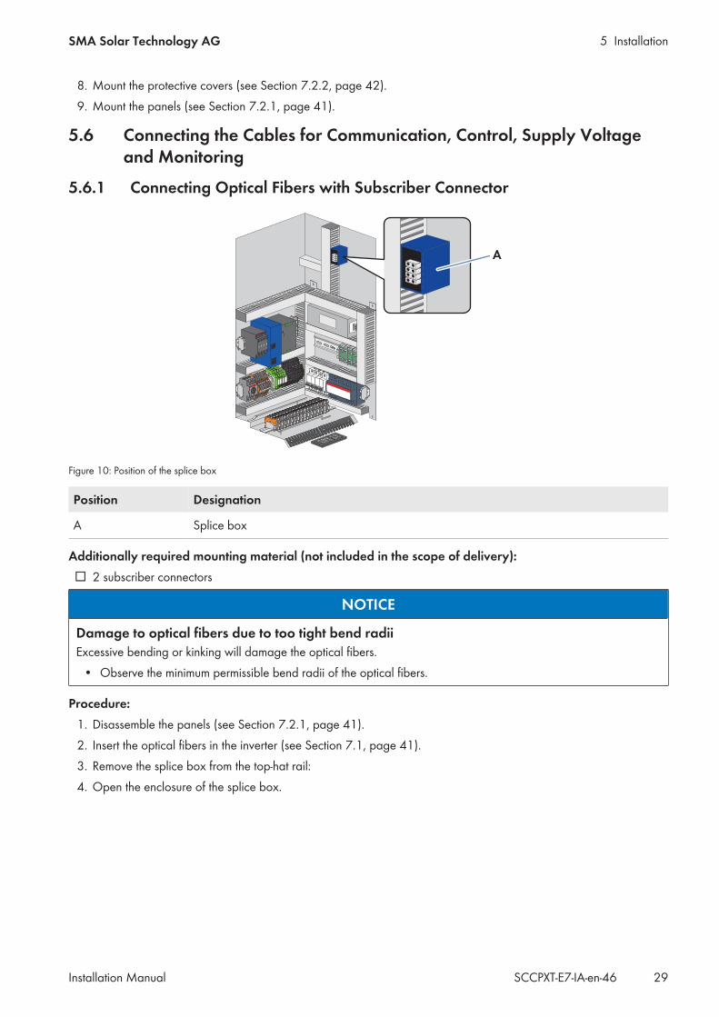
Figure 10: Position of the splice box
Position Designation
A Splice box
Additionally required mounting material (not included in the scope of delivery): 2 subscriber connectors
NOTICE
Damage to optical fibers due to too tight bend radiiExcessive bending or kinking will damage the optical fibers.
• Observe the minimum permissible bend radii of the optical fibers.
Procedure:1. Disassemble the panels (see Section 7.2.1, page 41).2. Insert the optical fibers in the inverter (see Section 7.1, page 41).3. Remove the splice box from the top-hat rail:4. Open the enclosure of the splice box.

5 Installation SMA Solar Technology AG
Installation ManualSCCPXT-E7-IA-en-4630
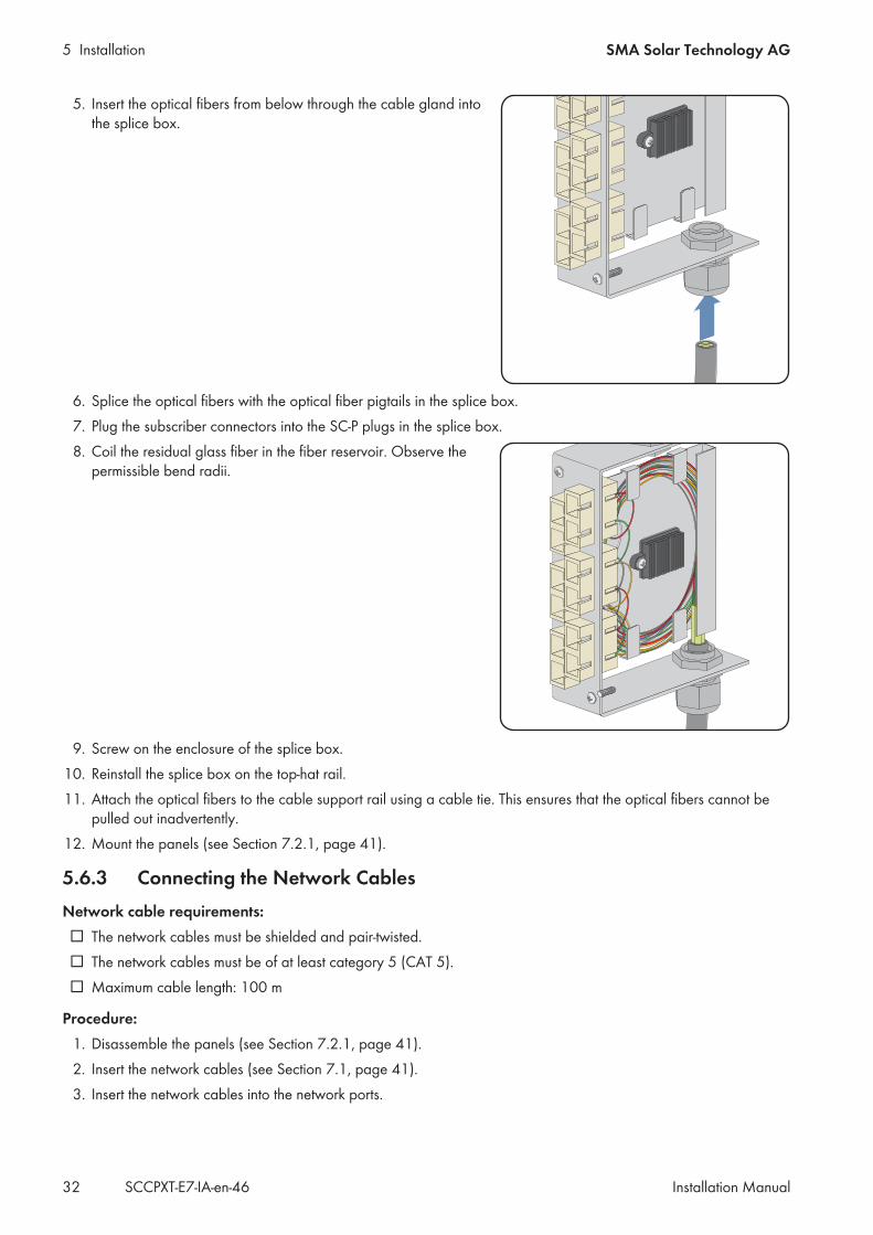
5. Insert the optical fibers from below through the cable gland intothe splice box.
6. Mount the subscriber connectors on the optical fibers.7. Plug the subscriber connectors into the SC-P plugs in the splice box.8. Coil the residual glass fiber in the fiber reservoir. Observe the
permissible bend radii.
9. Screw on the enclosure of the splice box.10. Reinstall the splice box on the top-hat rail.11. Attach the optical fibers to the cable support rail using a cable tie. This ensures that the optical fibers cannot be
pulled out inadvertently.12. Mount the panels (see Section 7.2.1, page 41).
5 InstallationSMA Solar Technology AG
Installation Manual 31SCCPXT-E7-IA-en-46
5.6.2 Connecting Optical Fibers via Optical Fiber Pigtail
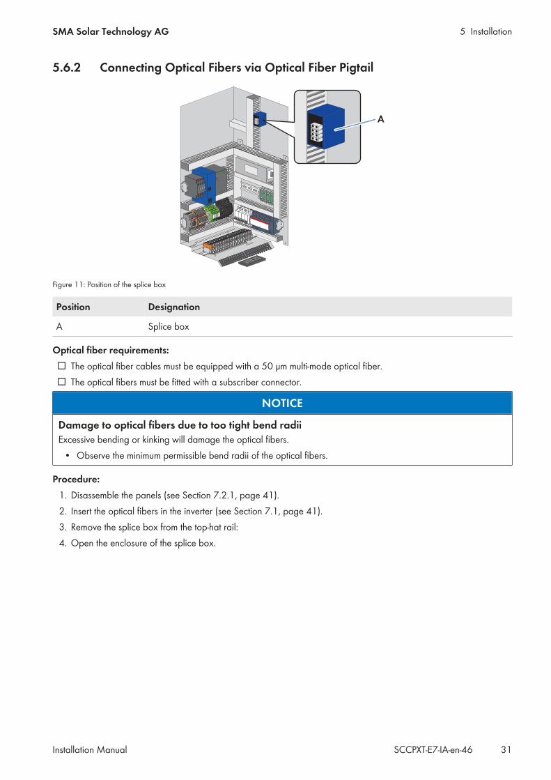
Figure 11: Position of the splice box
Position Designation
A Splice box
Optical fiber requirements: The optical fiber cables must be equipped with a 50 μm multi-mode optical fiber. The optical fibers must be fitted with a subscriber connector.
NOTICE
Damage to optical fibers due to too tight bend radiiExcessive bending or kinking will damage the optical fibers.
• Observe the minimum permissible bend radii of the optical fibers.
Procedure:1. Disassemble the panels (see Section 7.2.1, page 41).2. Insert the optical fibers in the inverter (see Section 7.1, page 41).3. Remove the splice box from the top-hat rail:4. Open the enclosure of the splice box.
5 Installation SMA Solar Technology AG
Installation ManualSCCPXT-E7-IA-en-4632
5. Insert the optical fibers from below through the cable gland intothe splice box.
6. Splice the optical fibers with the optical fiber pigtails in the splice box.7. Plug the subscriber connectors into the SC-P plugs in the splice box.8. Coil the residual glass fiber in the fiber reservoir. Observe the
permissible bend radii.
9. Screw on the enclosure of the splice box.10. Reinstall the splice box on the top-hat rail.11. Attach the optical fibers to the cable support rail using a cable tie. This ensures that the optical fibers cannot be
pulled out inadvertently.12. Mount the panels (see Section 7.2.1, page 41).
5.6.3 Connecting the Network CablesNetwork cable requirements: The network cables must be shielded and pair-twisted. The network cables must be of at least category 5 (CAT 5). Maximum cable length: 100 m
Procedure:1. Disassemble the panels (see Section 7.2.1, page 41).2. Insert the network cables (see Section 7.1, page 41).3. Insert the network cables into the network ports.
5 InstallationSMA Solar Technology AG
Installation Manual 33SCCPXT-E7-IA-en-46
4. Attach the network cables to the cable support rail using a cable tie. This will prevent the network cables frombeing pulled out inadvertently.
5. Mount the panels (see Section 7.2.1, page 41).
5.6.4 Connecting Cables for Analog SetpointsIf the setpoints for active power limitation and reactive power control are not transmitted via the network, there areterminals in the inverter for connecting external setpoints. The inverter processes standard analog signals from 4.0 mAto 20.0 mA.
Cable requirement: The cable used must be shielded.
Procedure:1. Disassemble the panels (see Section 7.2.1, page 41).2. Insert the cables (see Section 7.1, page 41).3. Connect the cables in accordance with the circuit diagram (see Section 7.4, page 50).4. Secure the cables on the cable support rail. This will prevent the cables from being pulled out inadvertently.5. Mount the panels (see Section 7.2.1, page 41).
5.6.5 Connecting the Cable for the External Fast StopIf required, you can connect an external fast stop in accordance with the circuit diagram. The fast stop can beoperated by means of an internal or external supply voltage.
Shortfall of external supply voltageIf there is an external supply voltage between 18.5 V to 24.0 V, the inverter will continue to operate in its currentoperating state. If the external supply voltage falls below 18.5 V, the inverter switches from the current operatingstate to the operating state "Stop". If the temperature inside the inverter exceeds the temperature limit, a supplyvoltage of 20.0 V to 24.0 V must be present to continue operating the inverter in its current operating state.Temperature limit: +60°C
• Ensure that the external supply voltage is between 20.0 V and 24.0 V.
Cable requirement: The cable used must be shielded.
Additional cable requirements for internal supply voltage: Maximum cable length with cable cross-section: 130 m / 2.5 mm² Maximum cable length with cable cross-section: 80 m / 1.5 mm²
Requirements: A switch must be used that can interrupt the supply voltage.
Procedure:1. Disassemble the panels (see Section 7.2.1, page 41).2. Insert the cables (see Section 7.1, page 41).3. Connect the cables in accordance with the circuit diagram (see Section 7.4, page 50).4. Secure the cables on the cable support rail. This will prevent the cables from being pulled out inadvertently.5. Mount the panels (see Section 7.2.1, page 41).
5 Installation SMA Solar Technology AG
Installation ManualSCCPXT-E7-IA-en-4634
5.6.6 Connecting the Cable for Remote ShutdownThe remote shutdown enables the inverter to be switched off from a distance, e.g. from a control room. The function ofthe remote shutdown is similar to the stop function of the key switch.
Shortfall of external supply voltageIf there is an external supply voltage between 18.5 V to 24.0 V, the inverter will continue to operate in its currentoperating state. If the external supply voltage falls below 18.5 V, the inverter switches from the current operatingstate to the operating state "Stop". If the temperature inside the inverter exceeds the temperature limit, a supplyvoltage of 20.0 V to 24.0 V must be present to continue operating the inverter in its current operating state.Temperature limit: +60°C
• Ensure that the external supply voltage is between 20.0 V and 24.0 V.
Procedure:1. Disassemble the panels (see Section 7.2.1, page 41).2. Insert the cables (see Section 7.1, page 41).3. Connect the cables in accordance with the circuit diagram (see Section 7.4, page 50).4. Secure the cables on the cable support rail. This will prevent the cables from being pulled out inadvertently.5. Mount the panels (see Section 7.2.1, page 41).
5.6.7 Connecting the Cable for the Status Report of the Insulation MonitoringStatus reportThe switching status can be queried via a contact. For details of terminal assignment, see circuit diagram.
Requirements: The connected load must operate with a voltage of 230 VAC or 24 VDC. The connected load must draw a current of 10 mA to 6 A.
Procedure:1. Disassemble the panels (see Section 7.2.1, page 41).2. Insert the cables (see Section 7.1, page 41).3. Connect the cables in accordance with the circuit diagram (see Section 7.4, page 50).4. Secure the cables on the cable support rail. This will prevent the cables from being pulled out inadvertently.5. Mount the panels (see Section 7.2.1, page 41).
5.6.8 Connecting the Cable for the Supply VoltageThe inverter must be connected to an external, three-phase supply voltage with 230 V line voltage/400 V line-to-linevoltage (3/N/PE) per line conductor.
Circuit breaker between the external supply voltage and the inverterA type-B circuit breaker with a rated current of 16 A is installed in the inverter.
• Provide a selective circuit breaker for insulating the cable to the inverter.
Cable requirements: The cable used must be shielded. Maximum conductor cross-section:4 mm².
5 InstallationSMA Solar Technology AG
Installation Manual 35SCCPXT-E7-IA-en-46
NOTICE
Failure of the inverter due to incorrect connection of the internal power supplyIf the internal power supply is not properly connected, the residual-current device in the inverter may trip and put theinverter is no longer ready for operation. This can result in financial damage due to yield loss.
• Connect the neutral conductor N.• Ground the neutral point of the internal power supply transformer.
Procedure:1. Disassemble the panels (see Section 7.2.1, page 41).2. Insert the cables (see Section 7.1, page 41).3. Connect the cables in accordance with the circuit diagram (see Section 7.4, page 50).4. Secure the cables on the cable support rail. This will prevent the cables from being pulled out inadvertently.5. Mount the panels (see Section 7.2.1, page 41).
5.6.9 Connecting the Cable for the Status Report of the AC Contactor MonitoringStatus reportThe switching status can be queried via a contact. For details of terminal assignment, see circuit diagram.
Requirements: The connected load must operate with a voltage of 230 VAC or 24 VDC. The connected load must draw a current of 10 mA to 6 A.
Procedure:1. Disassemble the panels (see Section 7.2.1, page 41).2. Insert the cables (see Section 7.1, page 41).3. Connect the cables in accordance with the circuit diagram (see Section 7.4, page 50).4. Secure the cables on the cable support rail. This will prevent the cables from being pulled out inadvertently.5. Mount the panels (see Section 7.2.1, page 41).
5.6.10 Connecting the Data Cable of the Sunny String-MonitorFor an optimum supply voltage, it is recommended to connect two insulated conductors each in the terminals of thesupply voltage and of the grounding.
Cable requirements: The supply voltage and the communication connection must be combined in one cable. The cable used must be shielded. Recommended cable type: Li2YCYv (TP) 4 x 2 x 0.5 mm².
Procedure:1. Disassemble the panels (see Section 7.2.1, page 41).2. Insert the cables (see Section 7.1, page 41).3. Connect the cables in accordance with the circuit diagram (see Section 7.4, page 50).4. Secure the cables on the cable support rail. This will prevent the cables from being pulled out inadvertently.5. Mount the panels (see Section 7.2.1, page 41).
5 Installation SMA Solar Technology AG
Installation ManualSCCPXT-E7-IA-en-4636
5.6.11 Connecting the Transformer ProtectionThe inverter is equipped with a terminal for monitoring the MV transformer. Under fault conditions, the inverter isimmediately switched off. To use the transformer monitoring, an external supply voltage of 230 V~ must be providedin the MV transformer.
Cable requirement: The cable used must be shielded.
Procedure:1. Disassemble the panels (see Section 7.2.1, page 41).2. Insert the cables (see Section 7.1, page 41).3. Connect the cables in accordance with the circuit diagram (see Section 7.4, page 50).4. Secure the cables on the cable support rail. This will prevent the cables from being pulled out inadvertently.5. Mount the panels (see Section 7.2.1, page 41).
6 Disconnecting and ReconnectingSMA Solar Technology AG
Installation Manual 37SCCPXT-E7-IA-en-46
6 Disconnecting and Reconnecting6.1 Safety When Disconnecting and Reconnecting Voltage Sources
DANGER
Danger to life from electric shock due to live voltageHigh voltages are present in the live components of the product. Touching live components results in death orserious injury due to electric shock.
• Wear suitable personal protective equipment for all work on the product.• Do not touch any live components.• Observe all warning messages on the product and in the documentation.• Observe all safety information of the module manufacturer.• After switching off the inverter, wait at least 15 minutes before opening it to allow the capacitors to discharge
completely (see Section 6.2, page 37).
DANGER
Danger to life from electric shock due to ground faultIf a ground fault has occurred, parts of the PV power plant that are supposedly grounded may in fact be live.Touching incorrectly grounded parts of the PV power plant results in death or serious injuries from electric shock.
• Before working on the PV power plant, ensure that no ground fault is present.• Wear suitable personal protective equipment for all work on the device.
CAUTION
Risk of burns due to hot componentsSome components of the product can get very hot during operation. Touching these components can cause burns.
• Observe the warnings on all components.• During operation, do not touch any components marked with such warnings.• After switching off the product, wait until any hot components have cooled down sufficiently.• Wear suitable personal protective equipment for all work on the product.
6.2 Disconnecting the Inverter
6.2.1 Switching off the Inverter1. Turn the key switch to Stop.2. Remove the key. This will protect the inverter from inadvertent reconnection.3. Wait 15 minutes before opening the doors. This allows the inverter capacitors to discharge.
6.2.2 Disconnecting the DC Side1. Switch off the inverter (see Section 6.2.1, page 37).2. Disconnect all poles of the DC voltage in the DC main distribution or DC subdistribution (see documentation of the
main or subdistribution).3. Ensure that the DC switchgear in the inverter is open.4. Ensure that no voltage is present on the load side of the DC switchgear.5. Cover or isolate any adjacent live components.
6 Disconnecting and Reconnecting SMA Solar Technology AG
Installation ManualSCCPXT-E7-IA-en-4638
6. Remove the protective covers over the fuses.7. Remove all fuses and disconnection blades from all fuse holders of the inverters. Use an LV/HRC fuse extractor.
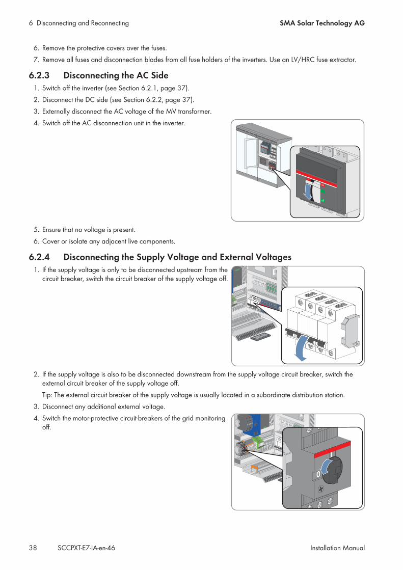
6.2.3 Disconnecting the AC Side1. Switch off the inverter (see Section 6.2.1, page 37).2. Disconnect the DC side (see Section 6.2.2, page 37).3. Externally disconnect the AC voltage of the MV transformer.4. Switch off the AC disconnection unit in the inverter.
5. Ensure that no voltage is present.6. Cover or isolate any adjacent live components.
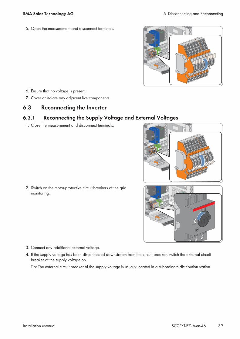
6.2.4 Disconnecting the Supply Voltage and External Voltages1. If the supply voltage is only to be disconnected upstream from the
circuit breaker, switch the circuit breaker of the supply voltage off.
2. If the supply voltage is also to be disconnected downstream from the supply voltage circuit breaker, switch theexternal circuit breaker of the supply voltage off.Tip: The external circuit breaker of the supply voltage is usually located in a subordinate distribution station.
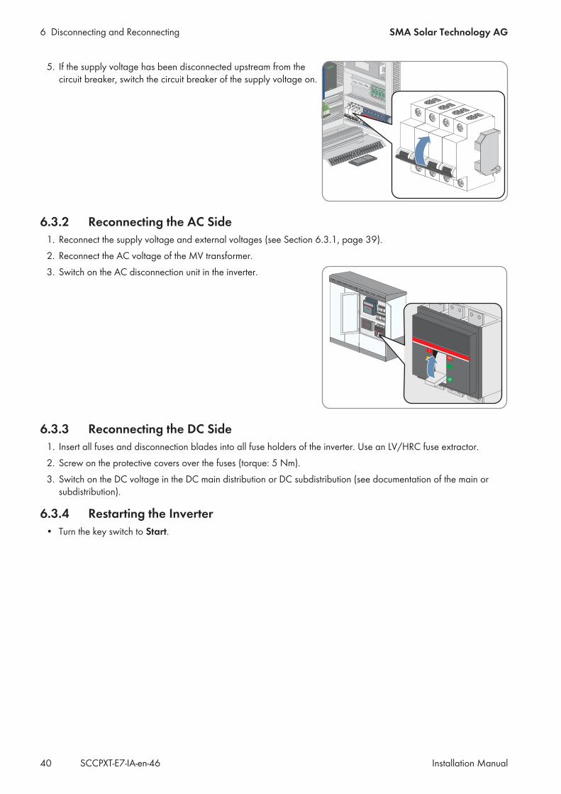
3. Disconnect any additional external voltage.4. Switch the motor-protective circuit-breakers of the grid monitoring
off.
6 Disconnecting and ReconnectingSMA Solar Technology AG
Installation Manual 39SCCPXT-E7-IA-en-46
5. Open the measurement and disconnect terminals.
6. Ensure that no voltage is present.7. Cover or isolate any adjacent live components.
6.3 Reconnecting the Inverter
6.3.1 Reconnecting the Supply Voltage and External Voltages1. Close the measurement and disconnect terminals.
2. Switch on the motor-protective circuit-breakers of the gridmonitoring.
3. Connect any additional external voltage.4. If the supply voltage has been disconnected downstream from the circuit breaker, switch the external circuit
breaker of the supply voltage on.Tip: The external circuit breaker of the supply voltage is usually located in a subordinate distribution station.
6 Disconnecting and Reconnecting SMA Solar Technology AG
Installation ManualSCCPXT-E7-IA-en-4640
5. If the supply voltage has been disconnected upstream from thecircuit breaker, switch the circuit breaker of the supply voltage on.
6.3.2 Reconnecting the AC Side1. Reconnect the supply voltage and external voltages (see Section 6.3.1, page 39).2. Reconnect the AC voltage of the MV transformer.3. Switch on the AC disconnection unit in the inverter.
6.3.3 Reconnecting the DC Side1. Insert all fuses and disconnection blades into all fuse holders of the inverter. Use an LV/HRC fuse extractor.2. Screw on the protective covers over the fuses (torque: 5 Nm).3. Switch on the DC voltage in the DC main distribution or DC subdistribution (see documentation of the main or
subdistribution).
6.3.4 Restarting the Inverter• Turn the key switch to Start.
7 Periodic ActionsSMA Solar Technology AG
Installation Manual 41SCCPXT-E7-IA-en-46
7 Periodic Actions7.1 Inserting the Cables
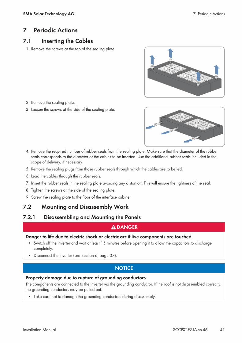
1. Remove the screws at the top of the sealing plate.
2. Remove the sealing plate.3. Loosen the screws at the side of the sealing plate.
4. Remove the required number of rubber seals from the sealing plate. Make sure that the diameter of the rubberseals corresponds to the diameter of the cables to be inserted. Use the additional rubber seals included in thescope of delivery, if necessary.
5. Remove the sealing plugs from those rubber seals through which the cables are to be led.6. Lead the cables through the rubber seals.7. Insert the rubber seals in the sealing plate avoiding any distortion. This will ensure the tightness of the seal.8. Tighten the screws at the side of the sealing plate.9. Screw the sealing plate to the floor of the interface cabinet.
7.2 Mounting and Disassembly Work
7.2.1 Disassembling and Mounting the Panels
DANGER
Danger to life due to electric shock or electric arc if live components are touched• Switch off the inverter and wait at least 15 minutes before opening it to allow the capacitors to discharge
completely.• Disconnect the inverter (see Section 6, page 37).
NOTICE
Property damage due to rupture of grounding conductorsThe components are connected to the inverter via the grounding conductor. If the roof is not disassembled correctly,the grounding conductors may be pulled out.
• Take care not to damage the grounding conductors during disassembly.
7 Periodic Actions SMA Solar Technology AG
Installation ManualSCCPXT-E7-IA-en-4642
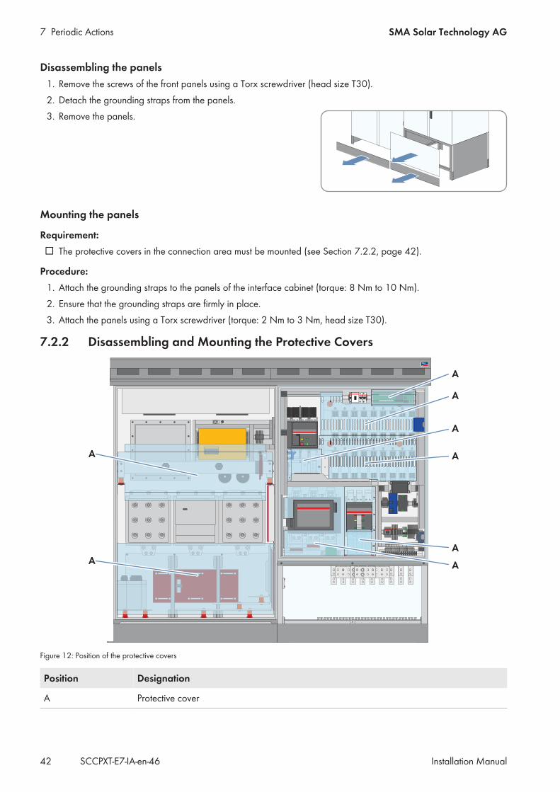
Disassembling the panels1. Remove the screws of the front panels using a Torx screwdriver (head size T30).2. Detach the grounding straps from the panels.3. Remove the panels.
Mounting the panels
Requirement: The protective covers in the connection area must be mounted (see Section 7.2.2, page 42).
Procedure:1. Attach the grounding straps to the panels of the interface cabinet (torque: 8 Nm to 10 Nm).2. Ensure that the grounding straps are firmly in place.3. Attach the panels using a Torx screwdriver (torque: 2 Nm to 3 Nm, head size T30).
7.2.2 Disassembling and Mounting the Protective Covers
Figure 12: Position of the protective covers
Position Designation
A Protective cover
7 Periodic ActionsSMA Solar Technology AG
Installation Manual 43SCCPXT-E7-IA-en-46
DANGER
Danger to life due to electric shock or electric arc if live components are touched• Switch off the inverter and wait at least 15 minutes before opening it to allow the capacitors to discharge
completely.• Disconnect the inverter (see Section 6, page 37).
Disassembling the protective covers
Requirements: The panels must be disassembled (see Section 7.2.1, page 41).
Procedure:• Disassemble the protective covers.
Mounting the protective covers1. Tighten all protective covers (torque: 5 Nm).2. Ensure that the protective covers are firmly in place.
7.2.3 Disassembling and Mounting the Ventilation Grids
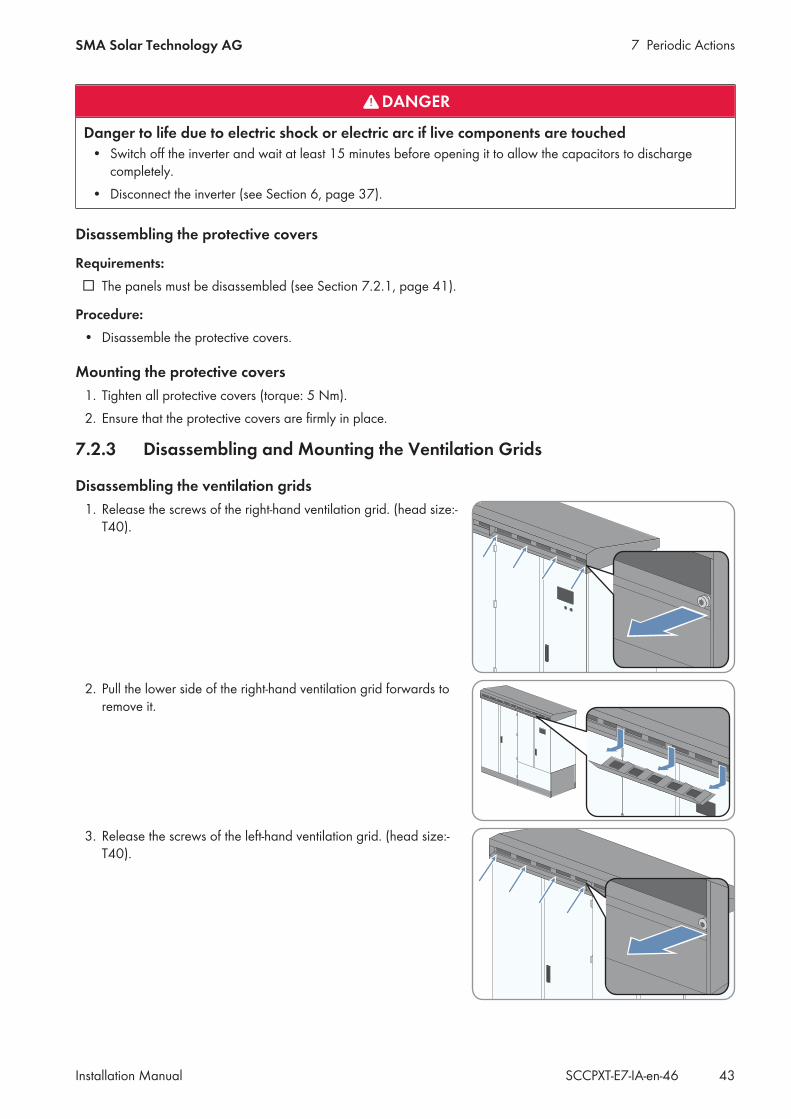
Disassembling the ventilation grids1. Release the screws of the right-hand ventilation grid. (head size:-
T40).
2. Pull the lower side of the right-hand ventilation grid forwards toremove it.
3. Release the screws of the left-hand ventilation grid. (head size:-T40).
7 Periodic Actions SMA Solar Technology AG
Installation ManualSCCPXT-E7-IA-en-4644
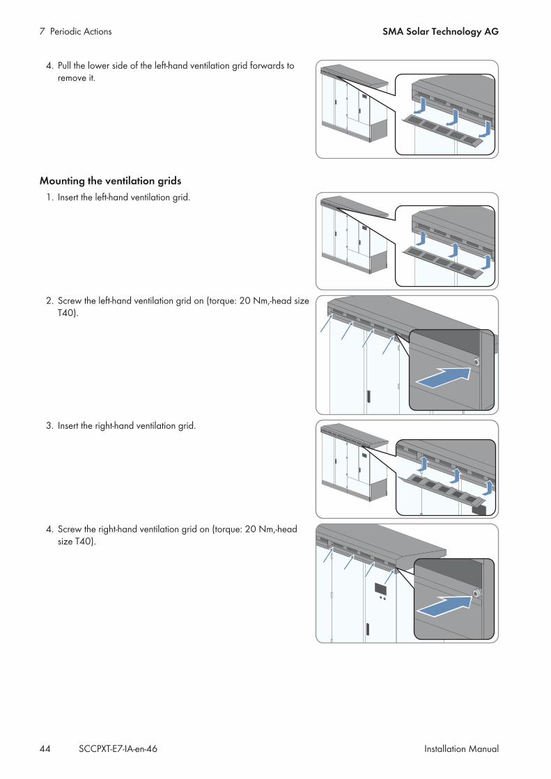
4. Pull the lower side of the left-hand ventilation grid forwards toremove it.
Mounting the ventilation grids1. Insert the left-hand ventilation grid.
2. Screw the left-hand ventilation grid on (torque: 20 Nm,-head sizeT40).
3. Insert the right-hand ventilation grid.
4. Screw the right-hand ventilation grid on (torque: 20 Nm,-headsize T40).
7 Periodic ActionsSMA Solar Technology AG
Installation Manual 45SCCPXT-E7-IA-en-46
7.3 Bolted Connections
7.3.1 Preparing the Grounding and DC Cables for Connection
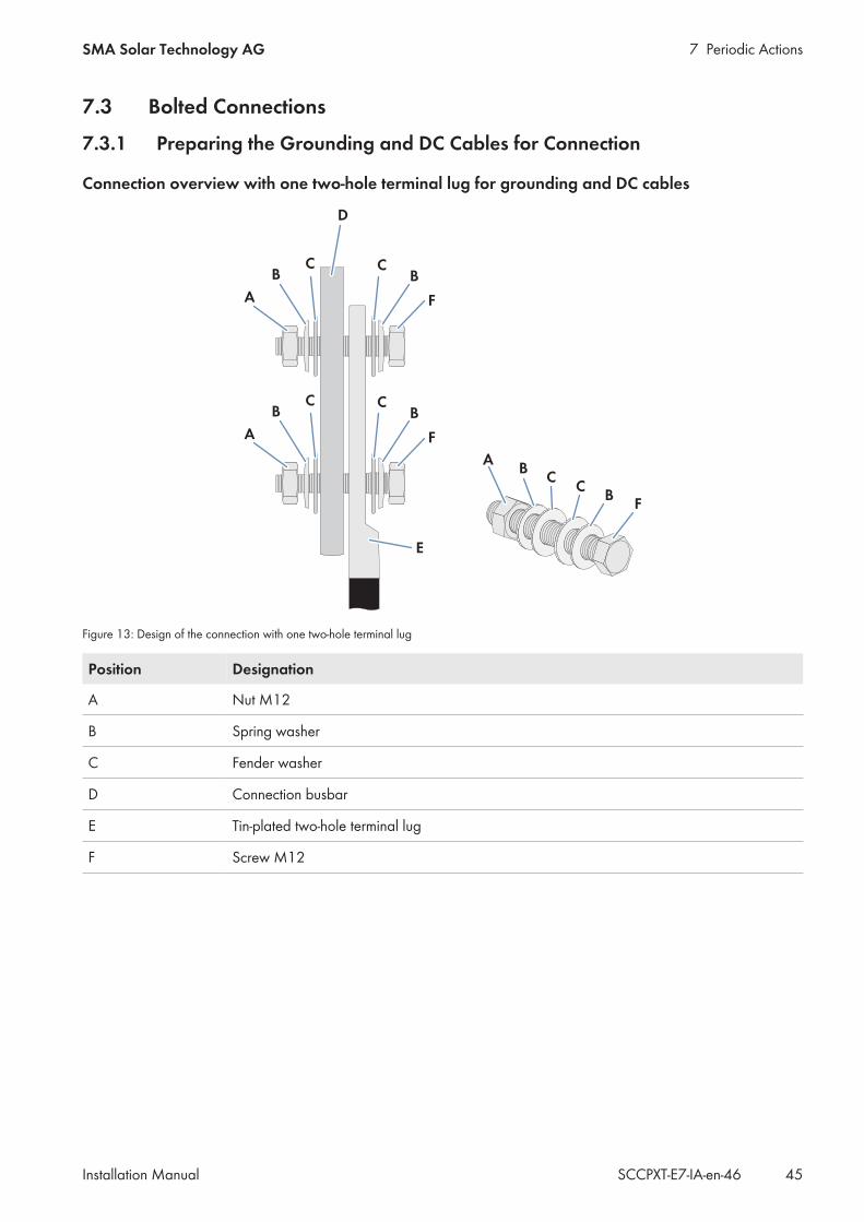
Connection overview with one two-hole terminal lug for grounding and DC cables
Figure 13: Design of the connection with one two-hole terminal lug
Position Designation
A Nut M12
B Spring washer
C Fender washer
D Connection busbar
E Tin-plated two-hole terminal lug
F Screw M12
7 Periodic Actions SMA Solar Technology AG
Installation ManualSCCPXT-E7-IA-en-4646
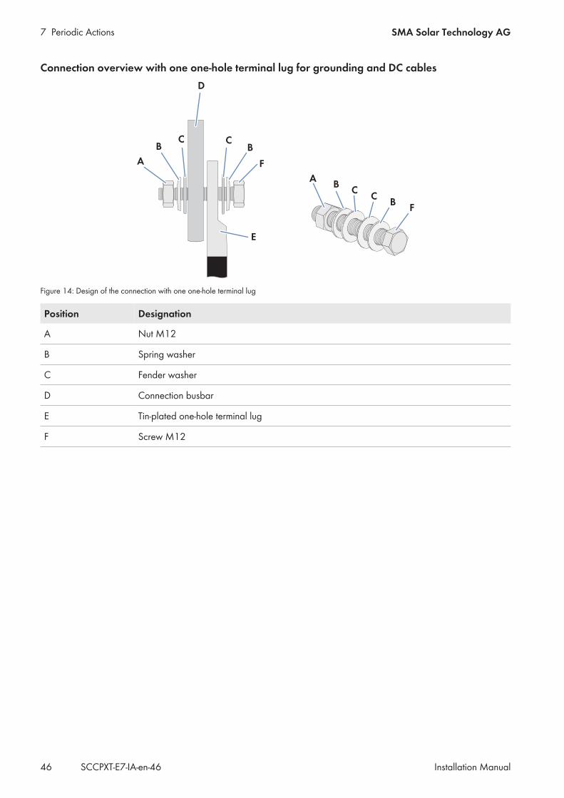
Connection overview with one one-hole terminal lug for grounding and DC cables
Figure 14: Design of the connection with one one-hole terminal lug
Position Designation
A Nut M12
B Spring washer
C Fender washer
D Connection busbar
E Tin-plated one-hole terminal lug
F Screw M12
7 Periodic ActionsSMA Solar Technology AG
Installation Manual 47SCCPXT-E7-IA-en-46
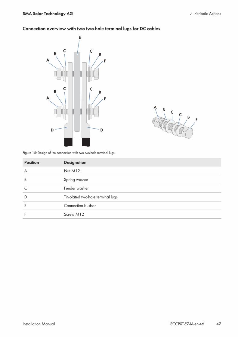
Connection overview with two two-hole terminal lugs for DC cables
Figure 15: Design of the connection with two two-hole terminal lugs
Position Designation
A Nut M12
B Spring washer
C Fender washer
D Tin-plated two-hole terminal lugs
E Connection busbar
F Screw M12
7 Periodic Actions SMA Solar Technology AG
Installation ManualSCCPXT-E7-IA-en-4648
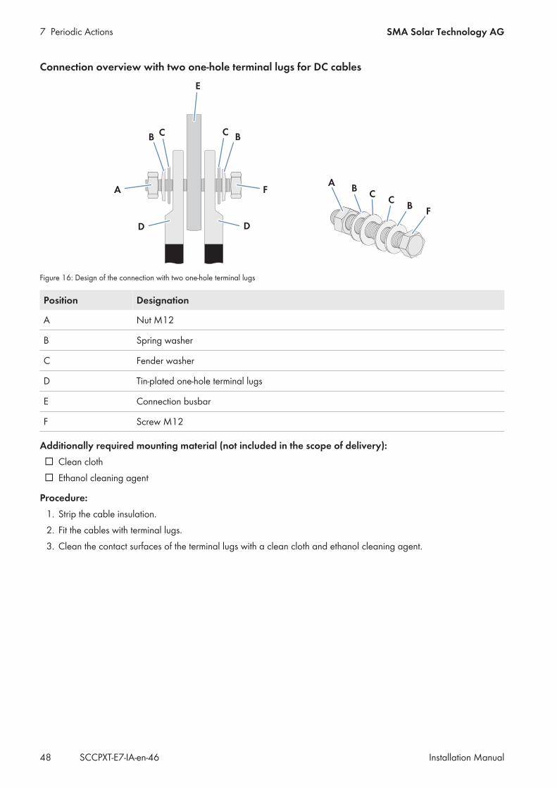
Connection overview with two one-hole terminal lugs for DC cables
Figure 16: Design of the connection with two one-hole terminal lugs
Position Designation
A Nut M12
B Spring washer
C Fender washer
D Tin-plated one-hole terminal lugs
E Connection busbar
F Screw M12
Additionally required mounting material (not included in the scope of delivery): Clean cloth Ethanol cleaning agent
Procedure:1. Strip the cable insulation.2. Fit the cables with terminal lugs.3. Clean the contact surfaces of the terminal lugs with a clean cloth and ethanol cleaning agent.
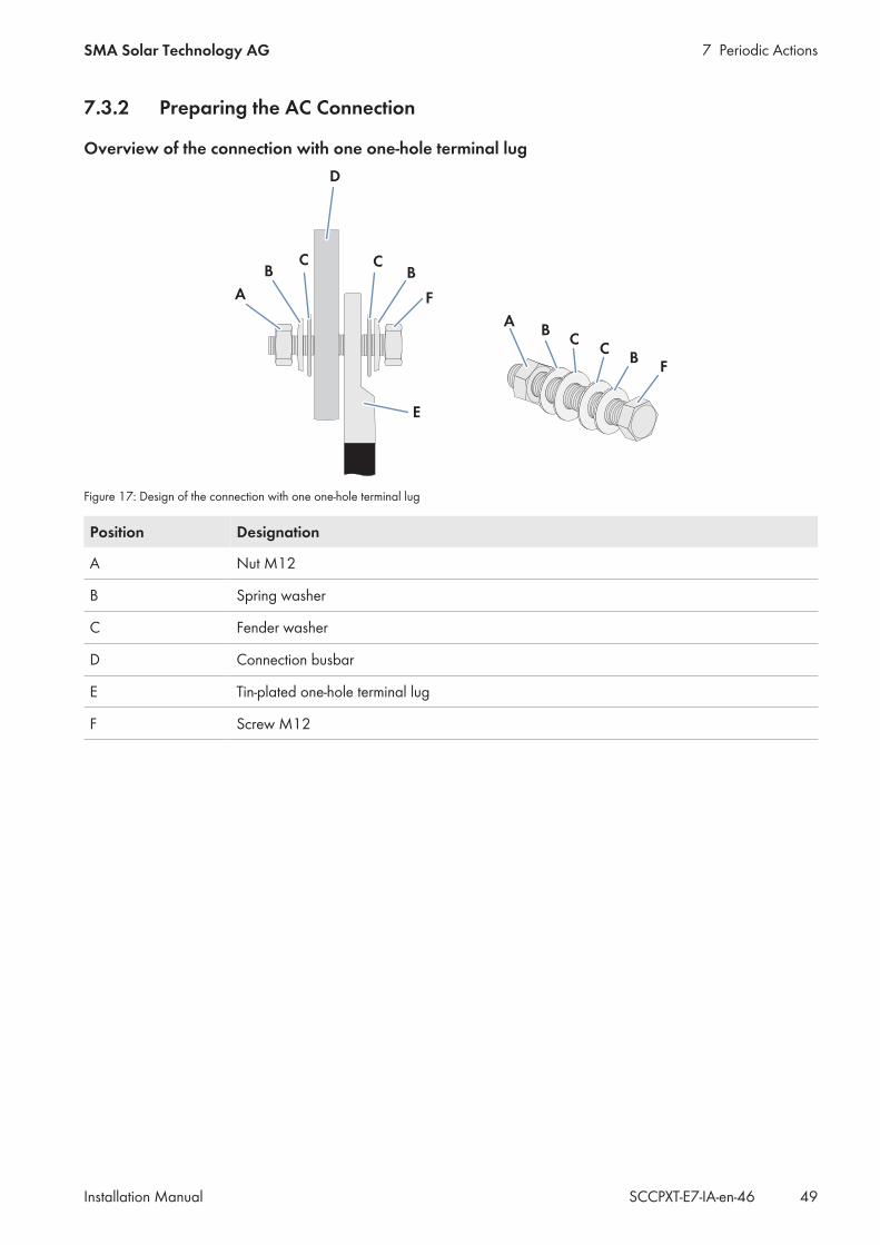
7 Periodic ActionsSMA Solar Technology AG
Installation Manual 49SCCPXT-E7-IA-en-46
7.3.2 Preparing the AC Connection
Overview of the connection with one one-hole terminal lug
Figure 17: Design of the connection with one one-hole terminal lug
Position Designation
A Nut M12
B Spring washer
C Fender washer
D Connection busbar
E Tin-plated one-hole terminal lug
F Screw M12
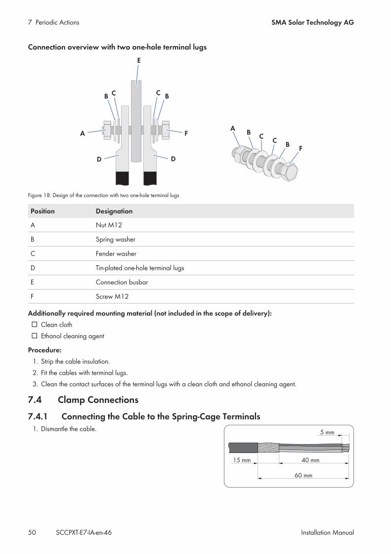
7 Periodic Actions SMA Solar Technology AG
Installation ManualSCCPXT-E7-IA-en-4650
Connection overview with two one-hole terminal lugs
Figure 18: Design of the connection with two one-hole terminal lugs
Position Designation
A Nut M12
B Spring washer
C Fender washer
D Tin-plated one-hole terminal lugs
E Connection busbar
F Screw M12
Additionally required mounting material (not included in the scope of delivery): Clean cloth Ethanol cleaning agent
Procedure:1. Strip the cable insulation.2. Fit the cables with terminal lugs.3. Clean the contact surfaces of the terminal lugs with a clean cloth and ethanol cleaning agent.
7.4 Clamp Connections
7.4.1 Connecting the Cable to the Spring-Cage Terminals1. Dismantle the cable.
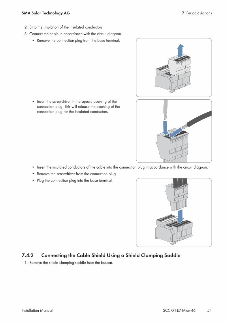
7 Periodic ActionsSMA Solar Technology AG
Installation Manual 51SCCPXT-E7-IA-en-46
2. Strip the insulation of the insulated conductors.3. Connect the cable in accordance with the circuit diagram.
• Remove the connection plug from the base terminal.
• Insert the screwdriver in the square opening of theconnection plug. This will release the opening of theconnection plug for the insulated conductors.
• Insert the insulated conductors of the cable into the connection plug in accordance with the circuit diagram.• Remove the screwdriver from the connection plug.• Plug the connection plug into the base terminal.
7.4.2 Connecting the Cable Shield Using a Shield Clamping Saddle1. Remove the shield clamping saddle from the busbar.
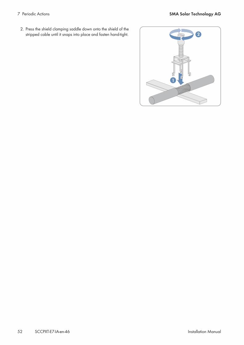
7 Periodic Actions SMA Solar Technology AG
Installation ManualSCCPXT-E7-IA-en-4652
2. Press the shield clamping saddle down onto the shield of thestripped cable until it snaps into place and fasten hand-tight.
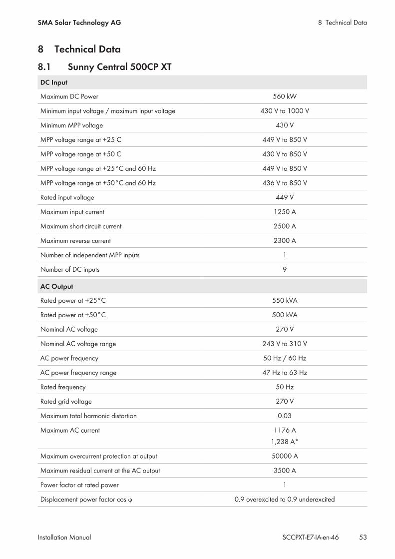
8 Technical DataSMA Solar Technology AG
Installation Manual 53SCCPXT-E7-IA-en-46
8 Technical Data8.1 Sunny Central 500CP XTDC Input
Maximum DC Power 560 kW
Minimum input voltage / maximum input voltage 430 V to 1000 V
Minimum MPP voltage 430 V
MPP voltage range at +25 C 449 V to 850 V
MPP voltage range at +50 C 430 V to 850 V
MPP voltage range at +25°C and 60 Hz 449 V to 850 V
MPP voltage range at +50°C and 60 Hz 436 V to 850 V
Rated input voltage 449 V
Maximum input current 1250 A
Maximum short-circuit current 2500 A
Maximum reverse current 2300 A
Number of independent MPP inputs 1
Number of DC inputs 9
AC Output
Rated power at +25°C 550 kVA
Rated power at +50°C 500 kVA
Nominal AC voltage 270 V
Nominal AC voltage range 243 V to 310 V
AC power frequency 50 Hz / 60 Hz
AC power frequency range 47 Hz to 63 Hz
Rated frequency 50 Hz
Rated grid voltage 270 V
Maximum total harmonic distortion 0.03
Maximum AC current 1176 A1,238 A*
Maximum overcurrent protection at output 50000 A
Maximum residual current at the AC output 3500 A
Power factor at rated power 1
Displacement power factor cos φ 0.9 overexcited to 0.9 underexcited

8 Technical Data SMA Solar Technology AG
Installation ManualSCCPXT-E7-IA-en-4654
AC Output
Feed-in phases 3
Connection phases 3
Inrush current of the internal power supply 48 A (100 ms)
* up to +5% Imax possible at Vac < Vacnom
Efficiency
Maximum efficiency 98.6%
European weighted efficiency 98.4%
CEC weighted efficiency 98.5%
Protective Devices
DC overvoltage protection Type I
Lightning protection as per IEC 62305-1 Lightning protection level III
Surge arrester for auxiliary power supply Yes
Protection class in accordance with IEC 62109-01 I
Overvoltage category in accordance with IEC 60664-1 III
General Data
Width x height x depth 2562 mm x 2272 mm x 956 mm
Weight 1900 kg
Operating temperature range −25°C to +62°C
Operating temperature range for low-temperature option −40°C to +62°C
Noise emission at a distance of 10 m 63 db(A)
Self-consumption in operation < 1,900 W
Standby consumption < 100 W
External supply voltage 230 V/400 V (3/N/PE), 50 Hz/60 Hz
Degree of protection of electronics IP54
Degree of protection of the connection area IP43
Maximum permissible value for relative humidity (non-condensing)
15% to 95%
Maximum operating altitude above mean sea level 2000 m
Maximum operating altitude above MSL for option "In-stallation at high altitudes"
4000 m
Fresh air consumption 3000 m³/h
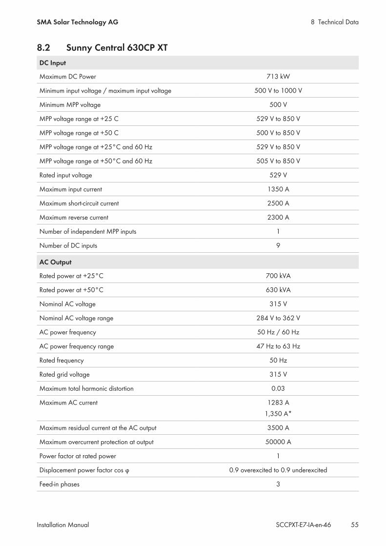
8 Technical DataSMA Solar Technology AG
Installation Manual 55SCCPXT-E7-IA-en-46
8.2 Sunny Central 630CP XTDC Input
Maximum DC Power 713 kW
Minimum input voltage / maximum input voltage 500 V to 1000 V
Minimum MPP voltage 500 V
MPP voltage range at +25 C 529 V to 850 V
MPP voltage range at +50 C 500 V to 850 V
MPP voltage range at +25°C and 60 Hz 529 V to 850 V
MPP voltage range at +50°C and 60 Hz 505 V to 850 V
Rated input voltage 529 V
Maximum input current 1350 A
Maximum short-circuit current 2500 A
Maximum reverse current 2300 A
Number of independent MPP inputs 1
Number of DC inputs 9
AC Output
Rated power at +25°C 700 kVA
Rated power at +50°C 630 kVA
Nominal AC voltage 315 V
Nominal AC voltage range 284 V to 362 V
AC power frequency 50 Hz / 60 Hz
AC power frequency range 47 Hz to 63 Hz
Rated frequency 50 Hz
Rated grid voltage 315 V
Maximum total harmonic distortion 0.03
Maximum AC current 1283 A1,350 A*
Maximum residual current at the AC output 3500 A
Maximum overcurrent protection at output 50000 A
Power factor at rated power 1
Displacement power factor cos φ 0.9 overexcited to 0.9 underexcited
Feed-in phases 3
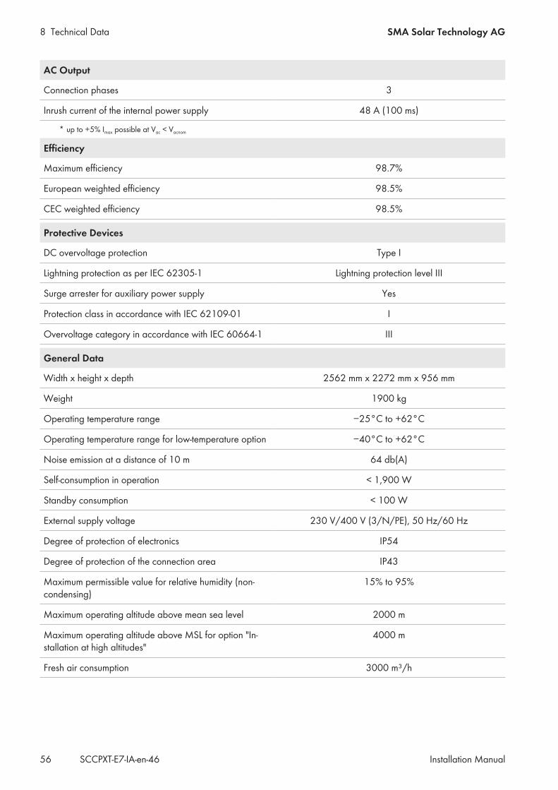
8 Technical Data SMA Solar Technology AG
Installation ManualSCCPXT-E7-IA-en-4656
AC Output
Connection phases 3
Inrush current of the internal power supply 48 A (100 ms)
* up to +5% Imax possible at Vac < Vacnom
Efficiency
Maximum efficiency 98.7%
European weighted efficiency 98.5%
CEC weighted efficiency 98.5%
Protective Devices
DC overvoltage protection Type I
Lightning protection as per IEC 62305-1 Lightning protection level III
Surge arrester for auxiliary power supply Yes
Protection class in accordance with IEC 62109-01 I
Overvoltage category in accordance with IEC 60664-1 III
General Data
Width x height x depth 2562 mm x 2272 mm x 956 mm
Weight 1900 kg
Operating temperature range −25°C to +62°C
Operating temperature range for low-temperature option −40°C to +62°C
Noise emission at a distance of 10 m 64 db(A)
Self-consumption in operation < 1,900 W
Standby consumption < 100 W
External supply voltage 230 V/400 V (3/N/PE), 50 Hz/60 Hz
Degree of protection of electronics IP54
Degree of protection of the connection area IP43
Maximum permissible value for relative humidity (non-condensing)
15% to 95%
Maximum operating altitude above mean sea level 2000 m
Maximum operating altitude above MSL for option "In-stallation at high altitudes"
4000 m
Fresh air consumption 3000 m³/h

8 Technical DataSMA Solar Technology AG
Installation Manual 57SCCPXT-E7-IA-en-46
8.3 Sunny Central 720CP XTDC Input
Maximum DC Power 808 kW
Minimum input voltage / maximum input voltage 480 V to 1000 V
Minimum MPP voltage 480 V
MPP voltage range at +25 C 577 V to 850 V
MPP voltage range at +50 C 525 V to 850 V
MPP voltage range at +25°C and 60 Hz 577 V to 850 V
MPP voltage range at +50°C and 60 Hz 525 V to 850 V
Rated input voltage 577 V
Maximum input current 1400 A
Maximum short-circuit current 2500 A
Maximum reverse current 2300 A
Number of independent MPP inputs 1
Number of DC inputs 9
AC Output
Rated power at +25°C 792 kVA
Rated power at +50°C 720 kVA
Nominal AC voltage 324 V
Nominal AC voltage range 292 V to 372 V
AC power frequency 50 Hz / 60 Hz
AC power frequency range 47 Hz to 63 Hz
Rated frequency 50 Hz
Rated grid voltage 324 V
Maximum total harmonic distortion 0.03
Maximum AC current 1411 A
Maximum residual current at the AC output 3500 A
Maximum overcurrent protection at output 50000 A
Power factor at rated power 1
Displacement power factor cos φ 0.9 overexcited to 0.9 underexcited
Feed-in phases 3
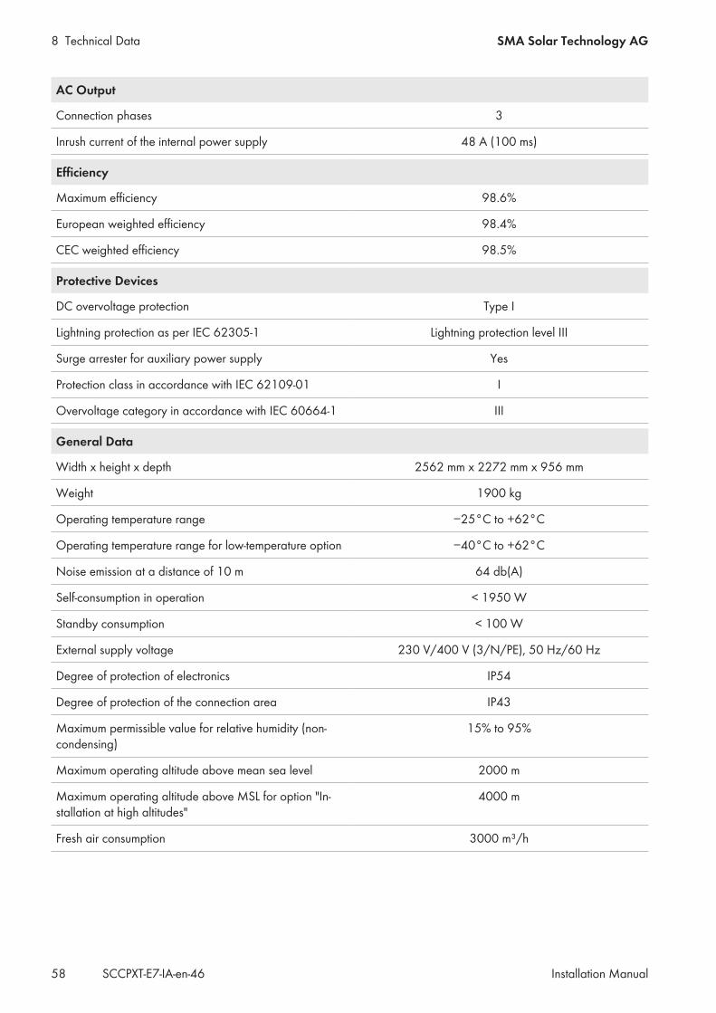
8 Technical Data SMA Solar Technology AG
Installation ManualSCCPXT-E7-IA-en-4658
AC Output
Connection phases 3
Inrush current of the internal power supply 48 A (100 ms)
Efficiency
Maximum efficiency 98.6%
European weighted efficiency 98.4%
CEC weighted efficiency 98.5%
Protective Devices
DC overvoltage protection Type I
Lightning protection as per IEC 62305-1 Lightning protection level III
Surge arrester for auxiliary power supply Yes
Protection class in accordance with IEC 62109-01 I
Overvoltage category in accordance with IEC 60664-1 III
General Data
Width x height x depth 2562 mm x 2272 mm x 956 mm
Weight 1900 kg
Operating temperature range −25°C to +62°C
Operating temperature range for low-temperature option −40°C to +62°C
Noise emission at a distance of 10 m 64 db(A)
Self-consumption in operation < 1950 W
Standby consumption < 100 W
External supply voltage 230 V/400 V (3/N/PE), 50 Hz/60 Hz
Degree of protection of electronics IP54
Degree of protection of the connection area IP43
Maximum permissible value for relative humidity (non-condensing)
15% to 95%
Maximum operating altitude above mean sea level 2000 m
Maximum operating altitude above MSL for option "In-stallation at high altitudes"
4000 m
Fresh air consumption 3000 m³/h
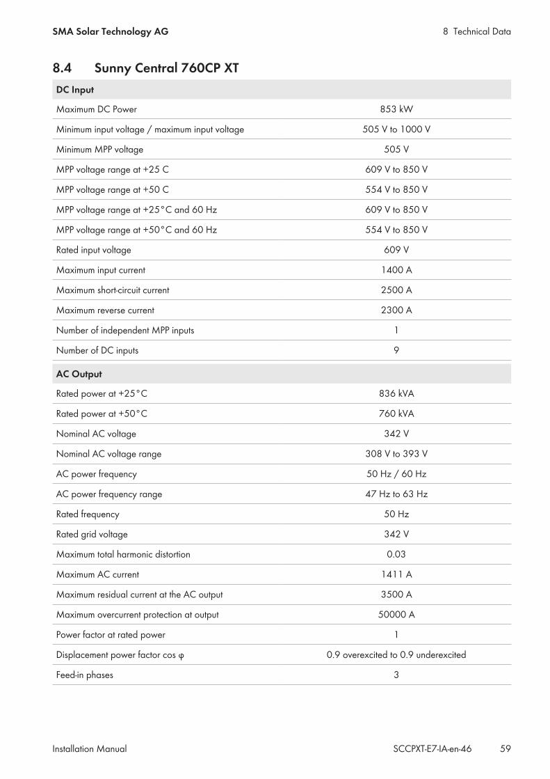
8 Technical DataSMA Solar Technology AG
Installation Manual 59SCCPXT-E7-IA-en-46
8.4 Sunny Central 760CP XTDC Input
Maximum DC Power 853 kW
Minimum input voltage / maximum input voltage 505 V to 1000 V
Minimum MPP voltage 505 V
MPP voltage range at +25 C 609 V to 850 V
MPP voltage range at +50 C 554 V to 850 V
MPP voltage range at +25°C and 60 Hz 609 V to 850 V
MPP voltage range at +50°C and 60 Hz 554 V to 850 V
Rated input voltage 609 V
Maximum input current 1400 A
Maximum short-circuit current 2500 A
Maximum reverse current 2300 A
Number of independent MPP inputs 1
Number of DC inputs 9
AC Output
Rated power at +25°C 836 kVA
Rated power at +50°C 760 kVA
Nominal AC voltage 342 V
Nominal AC voltage range 308 V to 393 V
AC power frequency 50 Hz / 60 Hz
AC power frequency range 47 Hz to 63 Hz
Rated frequency 50 Hz
Rated grid voltage 342 V
Maximum total harmonic distortion 0.03
Maximum AC current 1411 A
Maximum residual current at the AC output 3500 A
Maximum overcurrent protection at output 50000 A
Power factor at rated power 1
Displacement power factor cos φ 0.9 overexcited to 0.9 underexcited
Feed-in phases 3

8 Technical Data SMA Solar Technology AG
Installation ManualSCCPXT-E7-IA-en-4660
AC Output
Connection phases 3
Inrush current of the internal power supply 48 A (100 ms)
Efficiency
Maximum efficiency 98.6%
European weighted efficiency 98.4%
CEC weighted efficiency 98.5%
Protective Devices
DC overvoltage protection Type I
Lightning protection as per IEC 62305-1 Lightning protection level III
Surge arrester for auxiliary power supply Yes
Protection class in accordance with IEC 62109-01 I
Overvoltage category in accordance with IEC 60664-1 III
General Data
Width x height x depth 2562 mm x 2272 mm x 956 mm
Weight 1900 kg
Operating temperature range −25°C to +62°C
Operating temperature range for low-temperature option −40°C to +62°C
Noise emission at a distance of 10 m 64 db(A)
Self-consumption in operation < 1950 W
Standby consumption < 100 W
External supply voltage 230 V/400 V (3/N/PE), 50 Hz/60 Hz
Degree of protection of electronics IP54
Degree of protection of the connection area IP43
Maximum permissible value for relative humidity (non-condensing)
15% to 95%
Maximum operating altitude above mean sea level 2000 m
Maximum operating altitude above MSL for option "In-stallation at high altitudes"
4000 m
Fresh air consumption 3000 m³/h
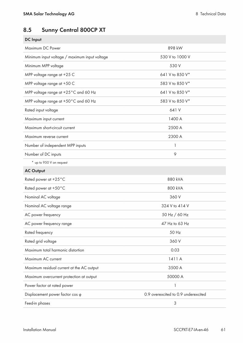
8 Technical DataSMA Solar Technology AG
Installation Manual 61SCCPXT-E7-IA-en-46
8.5 Sunny Central 800CP XTDC Input
Maximum DC Power 898 kW
Minimum input voltage / maximum input voltage 530 V to 1000 V
Minimum MPP voltage 530 V
MPP voltage range at +25 C 641 V to 850 V*
MPP voltage range at +50 C 583 V to 850 V*
MPP voltage range at +25°C and 60 Hz 641 V to 850 V*
MPP voltage range at +50°C and 60 Hz 583 V to 850 V*
Rated input voltage 641 V
Maximum input current 1400 A
Maximum short-circuit current 2500 A
Maximum reverse current 2300 A
Number of independent MPP inputs 1
Number of DC inputs 9
* up to 950 V on request
AC Output
Rated power at +25°C 880 kVA
Rated power at +50°C 800 kVA
Nominal AC voltage 360 V
Nominal AC voltage range 324 V to 414 V
AC power frequency 50 Hz / 60 Hz
AC power frequency range 47 Hz to 63 Hz
Rated frequency 50 Hz
Rated grid voltage 360 V
Maximum total harmonic distortion 0.03
Maximum AC current 1411 A
Maximum residual current at the AC output 3500 A
Maximum overcurrent protection at output 50000 A
Power factor at rated power 1
Displacement power factor cos φ 0.9 overexcited to 0.9 underexcited
Feed-in phases 3

8 Technical Data SMA Solar Technology AG
Installation ManualSCCPXT-E7-IA-en-4662
AC Output
Connection phases 3
Inrush current of the internal power supply 48 A (100 ms)
Efficiency
Maximum efficiency 98.6%
European weighted efficiency 98.4%
CEC weighted efficiency 98.5%
Protective Devices
DC overvoltage protection Type I
Lightning protection as per IEC 62305-1 Lightning protection level III
Surge arrester for auxiliary power supply Yes
Protection class in accordance with IEC 62109-01 I
Overvoltage category in accordance with IEC 60664-1 III
General Data
Width x height x depth 2562 mm x 2272 mm x 956 mm
Weight 1900 kg
Operating temperature range −25°C to +62°C
Operating temperature range for low-temperature option −40°C to +62°C
Noise emission at a distance of 10 m 64 db(A)
Self-consumption in operation < 1950 W
Standby consumption < 100 W
External supply voltage 230 V/400 V (3/N/PE), 50 Hz/60 Hz
Degree of protection of electronics IP54
Degree of protection of the connection area IP43
Maximum permissible value for relative humidity (non-condensing)
15% to 95%
Maximum operating altitude above mean sea level 2000 m
Maximum operating altitude above MSL for option "In-stallation at high altitudes"
4000 m
Fresh air consumption 3000 m³/h
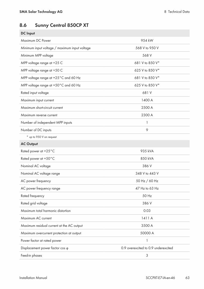
8 Technical DataSMA Solar Technology AG
Installation Manual 63SCCPXT-E7-IA-en-46
8.6 Sunny Central 850CP XTDC Input
Maximum DC Power 954 kW
Minimum input voltage / maximum input voltage 568 V to 950 V
Minimum MPP voltage 568 V
MPP voltage range at +25 C 681 V to 850 V*
MPP voltage range at +50 C 625 V to 850 V*
MPP voltage range at +25°C and 60 Hz 681 V to 850 V*
MPP voltage range at +50°C and 60 Hz 625 V to 850 V*
Rated input voltage 681 V
Maximum input current 1400 A
Maximum short-circuit current 2500 A
Maximum reverse current 2300 A
Number of independent MPP inputs 1
Number of DC inputs 9
* up to 950 V on request
AC Output
Rated power at +25°C 935 kVA
Rated power at +50°C 850 kVA
Nominal AC voltage 386 V
Nominal AC voltage range 348 V to 443 V
AC power frequency 50 Hz / 60 Hz
AC power frequency range 47 Hz to 63 Hz
Rated frequency 50 Hz
Rated grid voltage 386 V
Maximum total harmonic distortion 0.03
Maximum AC current 1411 A
Maximum residual current at the AC output 3500 A
Maximum overcurrent protection at output 50000 A
Power factor at rated power 1
Displacement power factor cos φ 0.9 overexcited to 0.9 underexcited
Feed-in phases 3

8 Technical Data SMA Solar Technology AG
Installation ManualSCCPXT-E7-IA-en-4664
AC Output
Connection phases 3
Inrush current of the internal power supply 48 A (100 ms)
Efficiency
Maximum efficiency 98.6%
European weighted efficiency 98.4%
CEC weighted efficiency 98.5%
Protective Devices
DC overvoltage protection Type I
Lightning protection as per IEC 62305-1 Lightning protection level III
Surge arrester for auxiliary power supply Yes
Protection class in accordance with IEC 62109-01 I
Overvoltage category in accordance with IEC 60664-1 III
General Data
Width x height x depth 2562 mm x 2272 mm x 956 mm
Weight 1900 kg
Operating temperature range −25°C to +62°C
Operating temperature range for low-temperature option −40°C to +62°C
Noise emission at a distance of 10 m 63 db(A)
Self-consumption in operation < 1950 W
Standby consumption < 100 W
External supply voltage 230 V/400 V (3/N/PE), 50 Hz/60 Hz
Degree of protection of electronics IP54
Degree of protection of the connection area IP43
Maximum permissible value for relative humidity (non-condensing)
15% to 95%
Maximum operating altitude above mean sea level 2000 m
Maximum operating altitude above MSL for option "In-stallation at high altitudes"
4000 m
Fresh air consumption 3000 m³/h

8 Technical DataSMA Solar Technology AG
Installation Manual 65SCCPXT-E7-IA-en-46
8.7 Sunny Central 900CP XTDC Input
Maximum DC Power 1010 kW
Minimum input voltage / maximum input voltage 596 V to 1000 V
Minimum MPP voltage 596 V
MPP voltage range at +25 C 722 V to 850 V*
MPP voltage range at +50 C 656 V to 850 V*
MPP voltage range at +25°C and 60 Hz 722 V to 850 V*
MPP voltage range at +50°C and 60 Hz 656 V to 850 V*
Rated input voltage 722 V
Maximum input current 1400 A
Maximum short-circuit current 2500 A
Maximum reverse current 2300 A
Number of independent MPP inputs 1
Number of DC inputs 9
* up to 950 V on request
AC Output
Rated power at +25°C 990 kVA
Rated power at +50°C 900 kVA
Nominal AC voltage 405 V
Nominal AC voltage range 365 V to 465 V
AC power frequency 50 Hz / 60 Hz
AC power frequency range 47 Hz to 63 Hz
Rated frequency 50 Hz
Rated grid voltage 405 V
Maximum total harmonic distortion 0.03
Maximum AC current 1411 A
Maximum residual current at the AC output 3500 A
Maximum overcurrent protection at output 50000 A
Power factor at rated power 1
Displacement power factor cos φ 0.9 overexcited to 0.9 underexcited
Feed-in phases 3

8 Technical Data SMA Solar Technology AG
Installation ManualSCCPXT-E7-IA-en-4666
AC Output
Connection phases 3
Inrush current of the internal power supply 48 A (100 ms)
Efficiency
Maximum efficiency 98.6%
European weighted efficiency 98.4%
CEC weighted efficiency 98.5%
Protective Devices
DC overvoltage protection Type I
Lightning protection as per IEC 62305-1 Lightning protection level III
Surge arrester for auxiliary power supply Yes
Protection class in accordance with IEC 62109-01 I
Overvoltage category in accordance with IEC 60664-1 III
General Data
Width x height x depth 2562 mm x 2272 mm x 956 mm
Weight 1900 kg
Operating temperature range −25°C to +62°C
Operating temperature range for low-temperature option −40°C to +62°C
Noise emission at a distance of 10 m 64 db(A)
Self-consumption in operation < 1950 W
Standby consumption < 100 W
External supply voltage 230 V/400 V (3/N/PE), 50 Hz/60 Hz
Degree of protection of electronics IP54
Degree of protection of the connection area IP43
Maximum permissible value for relative humidity (non-condensing)
15% to 95%
Maximum operating altitude above mean sea level 2000 m
Maximum operating altitude above MSL for option "In-stallation at high altitudes"
4000 m
Fresh air consumption 3000 m³/h
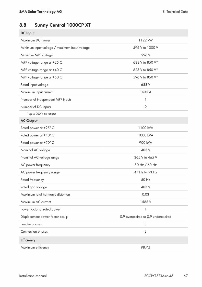
8 Technical DataSMA Solar Technology AG
Installation Manual 67SCCPXT-E7-IA-en-46
8.8 Sunny Central 1000CP XTDC Input
Maximum DC Power 1122 kW
Minimum input voltage / maximum input voltage 596 V to 1000 V
Minimum MPP voltage 596 V
MPP voltage range at +25 C 688 V to 850 V*
MPP voltage range at +40 C 625 V to 850 V*
MPP voltage range at +50 C 596 V to 850 V*
Rated input voltage 688 V
Maximum input current 1635 A
Number of independent MPP inputs 1
Number of DC inputs 9
* up to 900 V on request
AC Output
Rated power at +25°C 1100 kVA
Rated power at +40°C 1000 kVA
Rated power at +50°C 900 kVA
Nominal AC voltage 405 V
Nominal AC voltage range 365 V to 465 V
AC power frequency 50 Hz / 60 Hz
AC power frequency range 47 Hz to 63 Hz
Rated frequency 50 Hz
Rated grid voltage 405 V
Maximum total harmonic distortion 0.03
Maximum AC current 1568 V
Power factor at rated power 1
Displacement power factor cos φ 0.9 overexcited to 0.9 underexcited
Feed-in phases 3
Connection phases 3
Efficiency
Maximum efficiency 98.7%
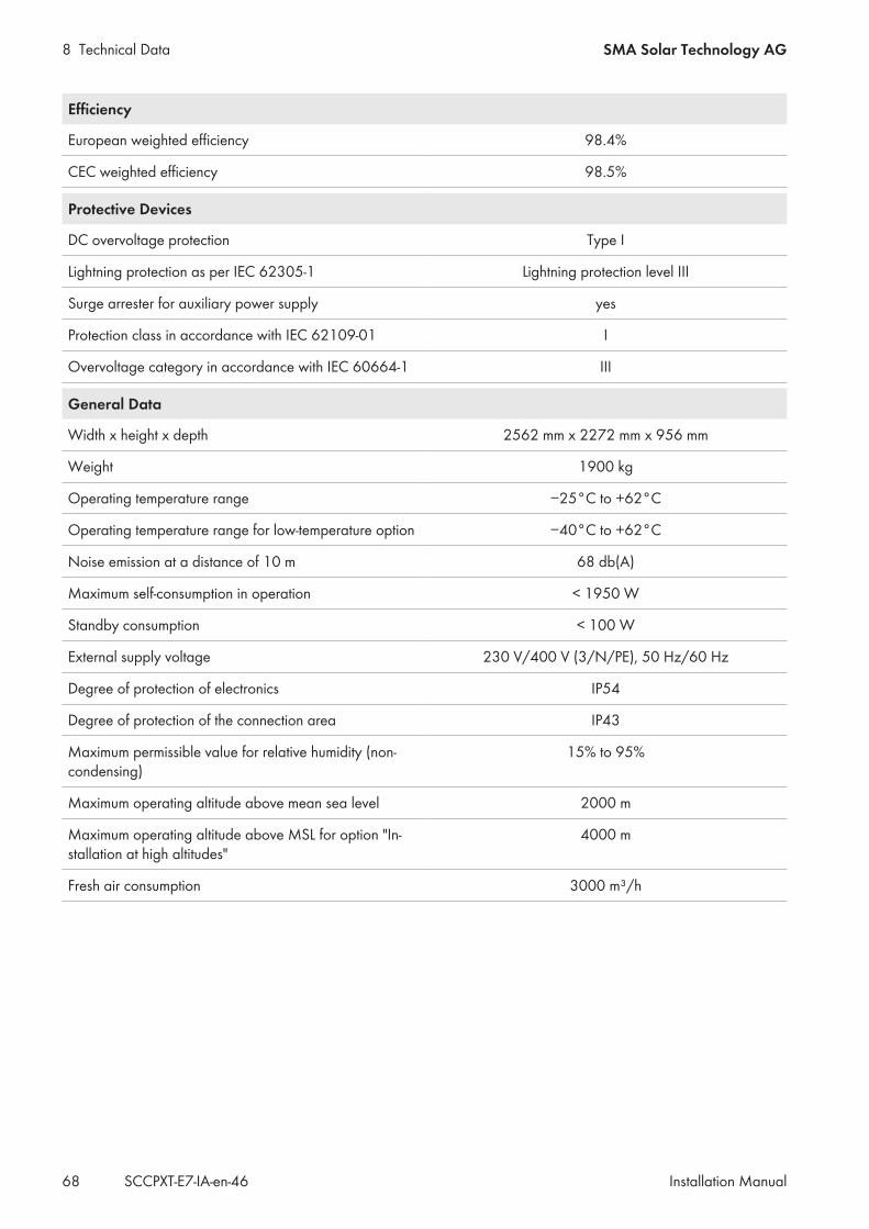
8 Technical Data SMA Solar Technology AG
Installation ManualSCCPXT-E7-IA-en-4668
Efficiency
European weighted efficiency 98.4%
CEC weighted efficiency 98.5%
Protective Devices
DC overvoltage protection Type I
Lightning protection as per IEC 62305-1 Lightning protection level III
Surge arrester for auxiliary power supply yes
Protection class in accordance with IEC 62109-01 I
Overvoltage category in accordance with IEC 60664-1 III
General Data
Width x height x depth 2562 mm x 2272 mm x 956 mm
Weight 1900 kg
Operating temperature range −25°C to +62°C
Operating temperature range for low-temperature option −40°C to +62°C
Noise emission at a distance of 10 m 68 db(A)
Maximum self-consumption in operation < 1950 W
Standby consumption < 100 W
External supply voltage 230 V/400 V (3/N/PE), 50 Hz/60 Hz
Degree of protection of electronics IP54
Degree of protection of the connection area IP43
Maximum permissible value for relative humidity (non-condensing)
15% to 95%
Maximum operating altitude above mean sea level 2000 m
Maximum operating altitude above MSL for option "In-stallation at high altitudes"
4000 m
Fresh air consumption 3000 m³/h
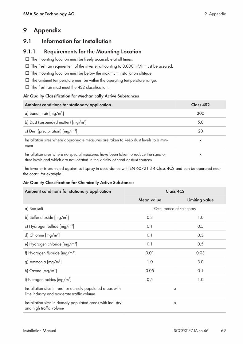
9 AppendixSMA Solar Technology AG
Installation Manual 69SCCPXT-E7-IA-en-46
9 Appendix9.1 Information for Installation
9.1.1 Requirements for the Mounting Location The mounting location must be freely accessible at all times. The fresh air requirement of the inverter amounting to 3,000 m3/h must be assured. The mounting location must be below the maximum installation altitude. The ambient temperature must be within the operating temperature range. The fresh air must meet the 4S2 classification.
Air Quality Classification for Mechanically Active Substances
Ambient conditions for stationary application Class 4S2
a) Sand in air [mg/m3] 300
b) Dust (suspended matter) [mg/m3] 5.0
c) Dust (precipitation) [mg/m3] 20
Installation sites where appropriate measures are taken to keep dust levels to a mini-mum
x
Installation sites where no special measures have been taken to reduce the sand ordust levels and which are not located in the vicinity of sand or dust sources
x
The inverter is protected against salt spray in accordance with EN 60721-3-4 Class 4C2 and can be operated nearthe coast, for example.
Air Quality Classification for Chemically Active Substances
Ambient conditions for stationary application Class 4C2
Mean value Limiting value
a) Sea salt Occurrence of salt spray
b) Sulfur dioxide [mg/m3] 0.3 1.0
c) Hydrogen sulfide [mg/m3] 0.1 0.5
d) Chlorine [mg/m3] 0.1 0.3
e) Hydrogen chloride [mg/m3] 0.1 0.5
f) Hydrogen fluoride [mg/m3] 0.01 0.03
g) Ammonia [mg/m3] 1.0 3.0
h) Ozone [mg/m3] 0.05 0.1
i) Nitrogen oxides [mg/m3] 0.5 1.0
Installation sites in rural or densely populated areas withlittle industry and moderate traffic volume
x
Installation sites in densely populated areas with industryand high traffic volume
x
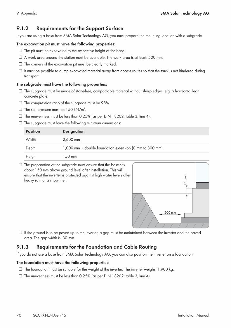
9 Appendix SMA Solar Technology AG
Installation ManualSCCPXT-E7-IA-en-4670
9.1.2 Requirements for the Support SurfaceIf you are using a base from SMA Solar Technology AG, you must prepare the mounting location with a subgrade.
The excavation pit must have the following properties: The pit must be excavated to the respective height of the base. A work area around the station must be available. The work area is at least: 500 mm. The corners of the excavation pit must be clearly marked. It must be possible to dump excavated material away from access routes so that the truck is not hindered during
transport.
The subgrade must have the following properties: The subgrade must be made of stone-free, compactable material without sharp edges, e.g. a horizontal lean
concrete plate. The compression ratio of the subgrade must be 98%. The soil pressure must be 150 kN/m2. The unevenness must be less than 0.25% (as per DIN 18202: table 3, line 4). The subgrade must have the following minimum dimensions:
Position Designation
Width 2,600 mm
Depth 1,000 mm + double foundation extension (0 mm to 300 mm)
Height 150 mm
The preparation of the subgrade must ensure that the base sitsabout 150 mm above ground level after installation. This willensure that the inverter is protected against high water levels afterheavy rain or a snow melt.
If the ground is to be paved up to the inverter, a gap must be maintained between the inverter and the pavedarea. The gap width is: 30 mm.
9.1.3 Requirements for the Foundation and Cable RoutingIf you do not use a base from SMA Solar Technology AG, you can also position the inverter on a foundation.
The foundation must have the following properties: The foundation must be suitable for the weight of the inverter. The inverter weighs: 1,900 kg. The unevenness must be less than 0.25% (as per DIN 18202: table 3, line 4).
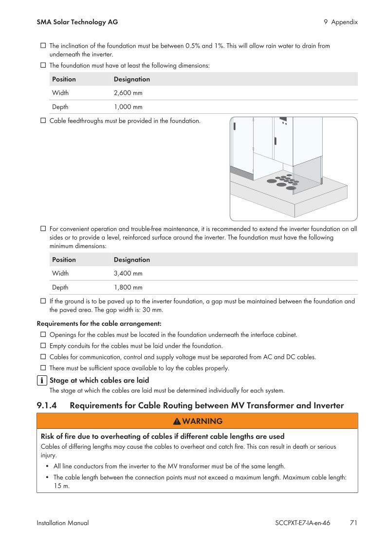
9 AppendixSMA Solar Technology AG
Installation Manual 71SCCPXT-E7-IA-en-46
The inclination of the foundation must be between 0.5% and 1%. This will allow rain water to drain fromunderneath the inverter.
The foundation must have at least the following dimensions:
Position Designation
Width 2,600 mm
Depth 1,000 mm
Cable feedthroughs must be provided in the foundation.
For convenient operation and trouble-free maintenance, it is recommended to extend the inverter foundation on allsides or to provide a level, reinforced surface around the inverter. The foundation must have the followingminimum dimensions:
Position Designation
Width 3,400 mm
Depth 1,800 mm
If the ground is to be paved up to the inverter foundation, a gap must be maintained between the foundation andthe paved area. The gap width is: 30 mm.
Requirements for the cable arrangement: Openings for the cables must be located in the foundation underneath the interface cabinet. Empty conduits for the cables must be laid under the foundation. Cables for communication, control and supply voltage must be separated from AC and DC cables. There must be sufficient space available to lay the cables properly.
Stage at which cables are laidThe stage at which the cables are laid must be determined individually for each system.
9.1.4 Requirements for Cable Routing between MV Transformer and Inverter
WARNING
Risk of fire due to overheating of cables if different cable lengths are usedCables of differing lengths may cause the cables to overheat and catch fire. This can result in death or seriousinjury.
• All line conductors from the inverter to the MV transformer must be of the same length.• The cable length between the connection points must not exceed a maximum length. Maximum cable length:
15 m.
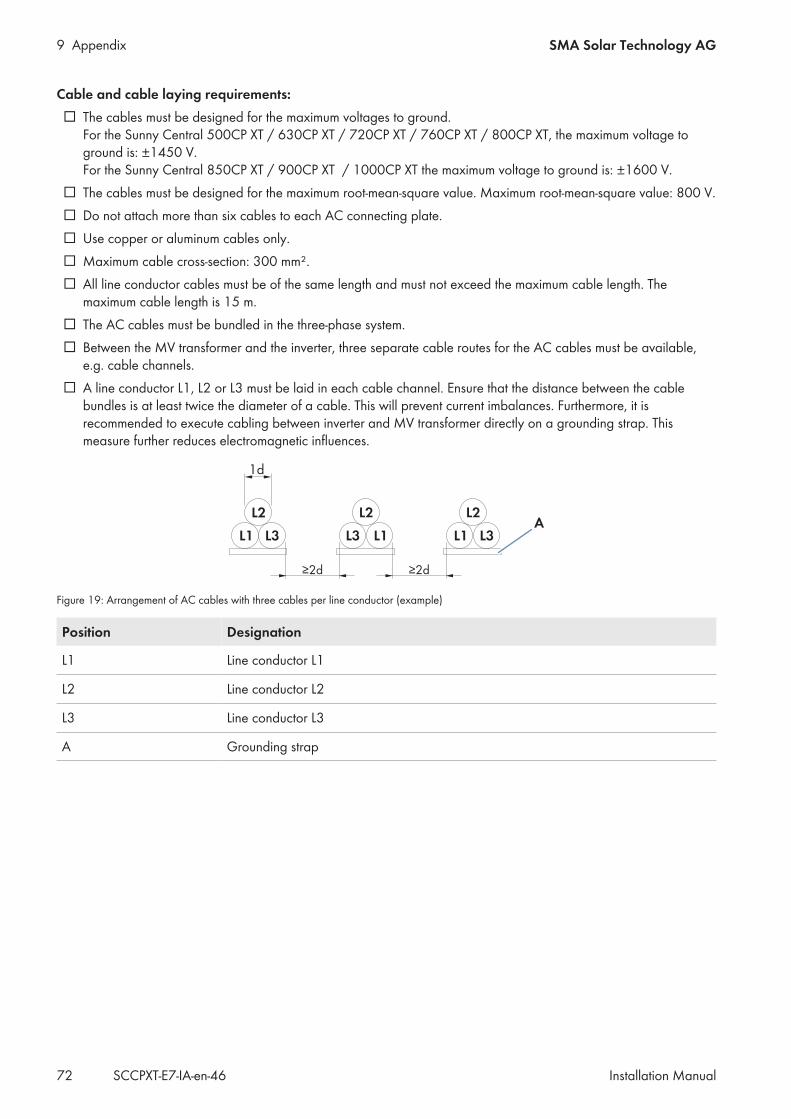
9 Appendix SMA Solar Technology AG
Installation ManualSCCPXT-E7-IA-en-4672
Cable and cable laying requirements: The cables must be designed for the maximum voltages to ground.
For the Sunny Central 500CP XT / 630CP XT / 720CP XT / 760CP XT / 800CP XT, the maximum voltage toground is: ±1450 V. For the Sunny Central 850CP XT / 900CP XT / 1000CP XT the maximum voltage to ground is: ±1600 V.
The cables must be designed for the maximum root-mean-square value. Maximum root-mean-square value: 800 V. Do not attach more than six cables to each AC connecting plate. Use copper or aluminum cables only. Maximum cable cross-section: 300 mm². All line conductor cables must be of the same length and must not exceed the maximum cable length. The
maximum cable length is 15 m. The AC cables must be bundled in the three-phase system. Between the MV transformer and the inverter, three separate cable routes for the AC cables must be available,
e.g. cable channels. A line conductor L1, L2 or L3 must be laid in each cable channel. Ensure that the distance between the cable
bundles is at least twice the diameter of a cable. This will prevent current imbalances. Furthermore, it isrecommended to execute cabling between inverter and MV transformer directly on a grounding strap. Thismeasure further reduces electromagnetic influences.
Figure 19: Arrangement of AC cables with three cables per line conductor (example)
Position Designation
L1 Line conductor L1
L2 Line conductor L2
L3 Line conductor L3
A Grounding strap
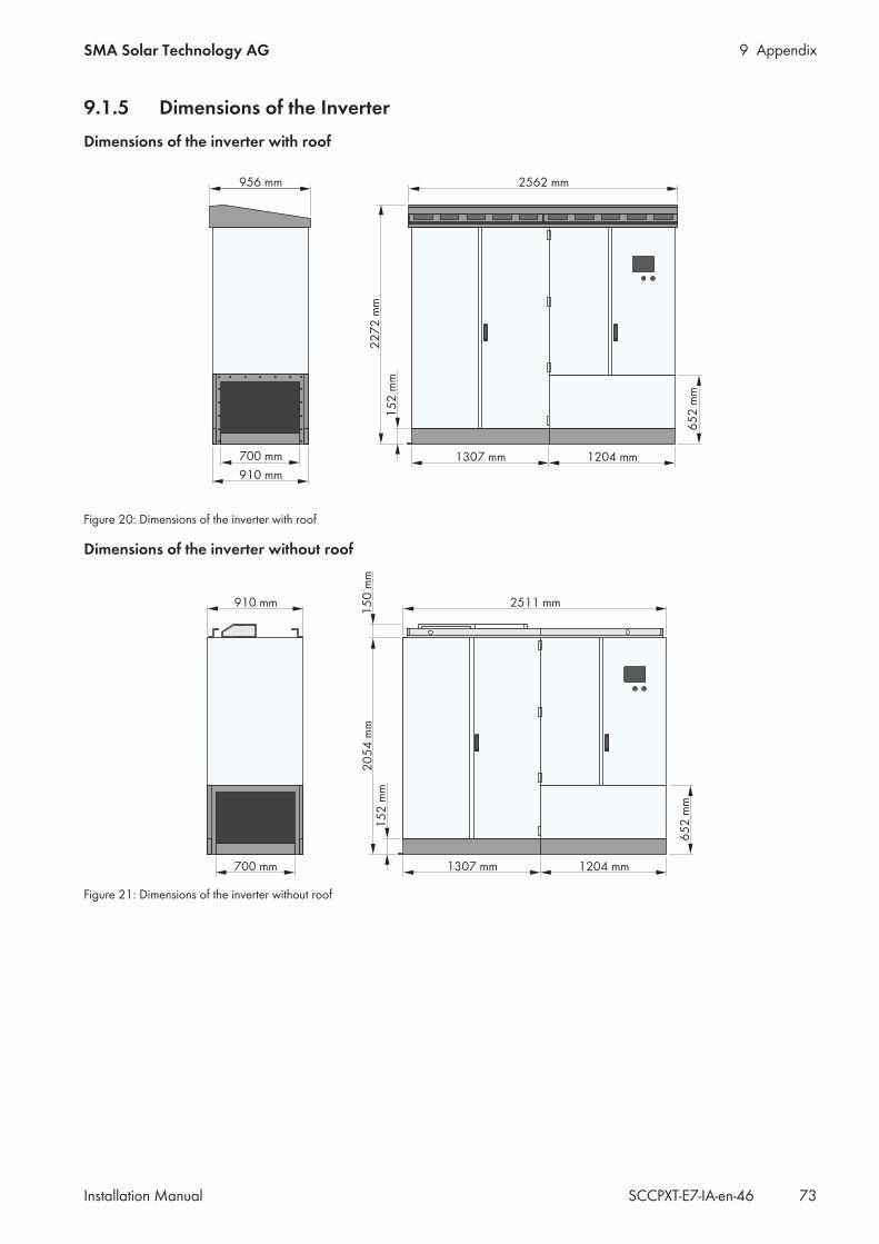
9 AppendixSMA Solar Technology AG
Installation Manual 73SCCPXT-E7-IA-en-46
9.1.5 Dimensions of the InverterDimensions of the inverter with roof
Figure 20: Dimensions of the inverter with roof
Dimensions of the inverter without roof
Figure 21: Dimensions of the inverter without roof
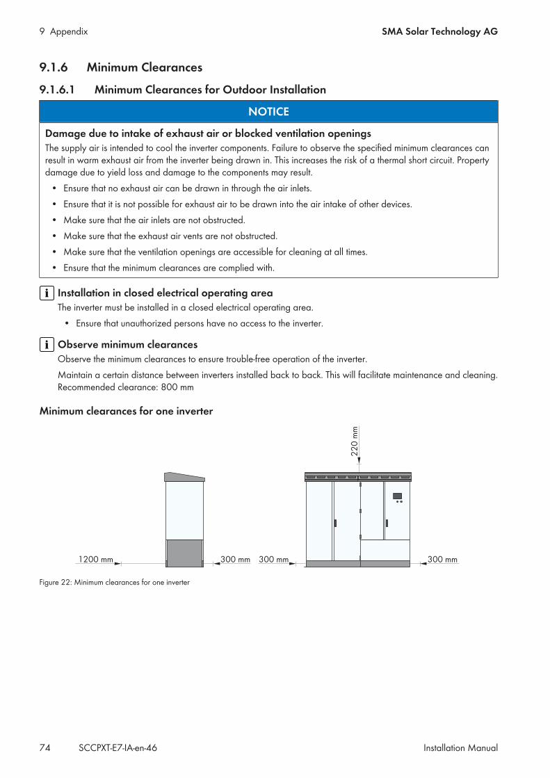
9 Appendix SMA Solar Technology AG
Installation ManualSCCPXT-E7-IA-en-4674
9.1.6 Minimum Clearances
9.1.6.1 Minimum Clearances for Outdoor Installation
NOTICE
Damage due to intake of exhaust air or blocked ventilation openingsThe supply air is intended to cool the inverter components. Failure to observe the specified minimum clearances canresult in warm exhaust air from the inverter being drawn in. This increases the risk of a thermal short circuit. Propertydamage due to yield loss and damage to the components may result.
• Ensure that no exhaust air can be drawn in through the air inlets.• Ensure that it is not possible for exhaust air to be drawn into the air intake of other devices.• Make sure that the air inlets are not obstructed.• Make sure that the exhaust air vents are not obstructed.• Make sure that the ventilation openings are accessible for cleaning at all times.• Ensure that the minimum clearances are complied with.
Installation in closed electrical operating areaThe inverter must be installed in a closed electrical operating area.
• Ensure that unauthorized persons have no access to the inverter.
Observe minimum clearancesObserve the minimum clearances to ensure trouble-free operation of the inverter.Maintain a certain distance between inverters installed back to back. This will facilitate maintenance and cleaning.Recommended clearance: 800 mm
Minimum clearances for one inverter
Figure 22: Minimum clearances for one inverter
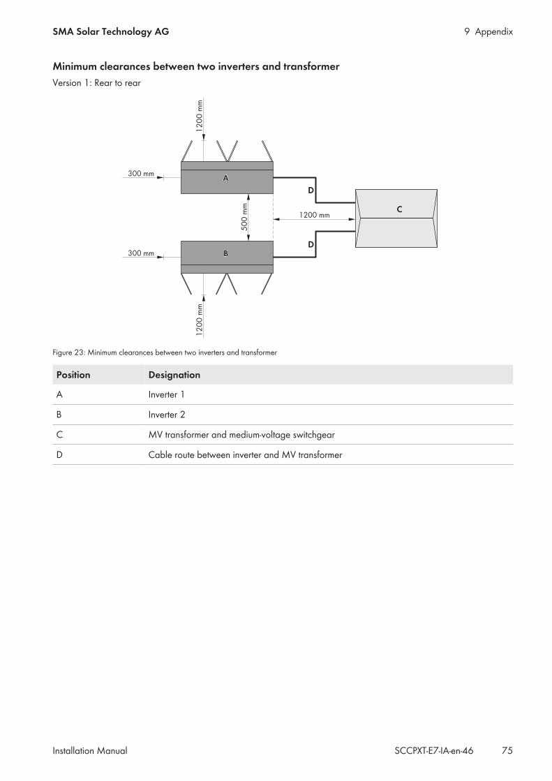
9 AppendixSMA Solar Technology AG
Installation Manual 75SCCPXT-E7-IA-en-46
Minimum clearances between two inverters and transformerVersion 1: Rear to rear
Figure 23: Minimum clearances between two inverters and transformer
Position Designation
A Inverter 1
B Inverter 2
C MV transformer and medium-voltage switchgear
D Cable route between inverter and MV transformer
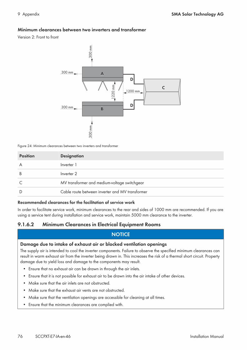
9 Appendix SMA Solar Technology AG
Installation ManualSCCPXT-E7-IA-en-4676
Minimum clearances between two inverters and transformerVersion 2: Front to front
Figure 24: Minimum clearances between two inverters and transformer
Position Designation
A Inverter 1
B Inverter 2
C MV transformer and medium-voltage switchgear
D Cable route between inverter and MV transformer
Recommended clearances for the facilitation of service workIn order to facilitate service work, minimum clearances to the rear and sides of 1000 mm are recommended. If you areusing a service tent during installation and service work, maintain 5000 mm clearance to the inverter.
9.1.6.2 Minimum Clearances in Electrical Equipment Rooms
NOTICE
Damage due to intake of exhaust air or blocked ventilation openingsThe supply air is intended to cool the inverter components. Failure to observe the specified minimum clearances canresult in warm exhaust air from the inverter being drawn in. This increases the risk of a thermal short circuit. Propertydamage due to yield loss and damage to the components may result.
• Ensure that no exhaust air can be drawn in through the air inlets.• Ensure that it is not possible for exhaust air to be drawn into the air intake of other devices.• Make sure that the air inlets are not obstructed.• Make sure that the exhaust air vents are not obstructed.• Make sure that the ventilation openings are accessible for cleaning at all times.• Ensure that the minimum clearances are complied with.
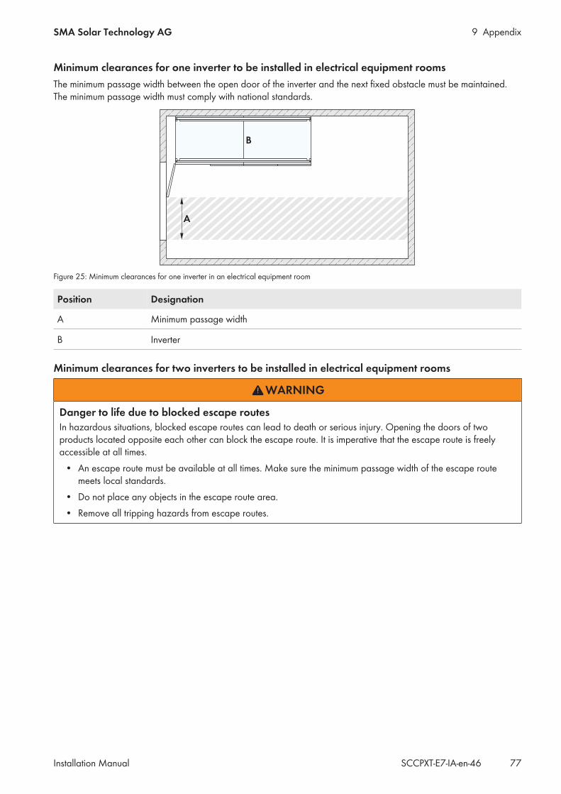
9 AppendixSMA Solar Technology AG
Installation Manual 77SCCPXT-E7-IA-en-46
Minimum clearances for one inverter to be installed in electrical equipment roomsThe minimum passage width between the open door of the inverter and the next fixed obstacle must be maintained.The minimum passage width must comply with national standards.
Figure 25: Minimum clearances for one inverter in an electrical equipment room
Position Designation
A Minimum passage width
B Inverter
Minimum clearances for two inverters to be installed in electrical equipment rooms
WARNING
Danger to life due to blocked escape routesIn hazardous situations, blocked escape routes can lead to death or serious injury. Opening the doors of twoproducts located opposite each other can block the escape route. It is imperative that the escape route is freelyaccessible at all times.
• An escape route must be available at all times. Make sure the minimum passage width of the escape routemeets local standards.
• Do not place any objects in the escape route area.• Remove all tripping hazards from escape routes.

9 Appendix SMA Solar Technology AG
Installation ManualSCCPXT-E7-IA-en-4678
The minimum passage width between the open door of the inverter and the next fixed obstacle must be maintained.The minimum passage width must comply with national standards.
Figure 26: Minimum clearances for two inverters in an electrical equipment room
Position Designation
A Minimum passage width
B Inverter
9.1.7 Grounding ConceptIn accordance with the latest technology, the inverters are discharged to ground. As a result, leakage currents toground occur which must be taken into account when planning the PV power plant. The magnitude and distribution ofsuch leakage currents is influenced by the grounding concept of all devices in the PV power plant. It is thereforerecommended that e.g. for use of cameras and monitoring technology, signal transmission is executed in fiber-optictechnology. This will counteract possible interference sources.The recommended grounding of inverter and MV transformer in meshed design reduces leakage current levels.
9.2 StorageIf you need to store the inverter prior to final installation, note the following points:
NOTICE
Property damage due to dust intrusion and moisture penetrationDust or moisture intrusion can damage the product and impair its functionality.
• Do not open the enclosure during rainfall or when humidity exceeds the specified thresholds. The humiditythresholds are: 15% to 95%.
• Only perform maintenance work when the environment is dry and free of dust.• Operation of the product is only permitted when it is closed.• Connect the external supply voltage after mounting and installing the product.• If the installation or commissioning process is interrupted, mount all panels.• Close and lock the enclosure.• The product must always be closed for storage.• Store the product in a dry and covered location.• Temperature at the storage location must be in the specified range. The temperature range is:
−25°C to +70°C.
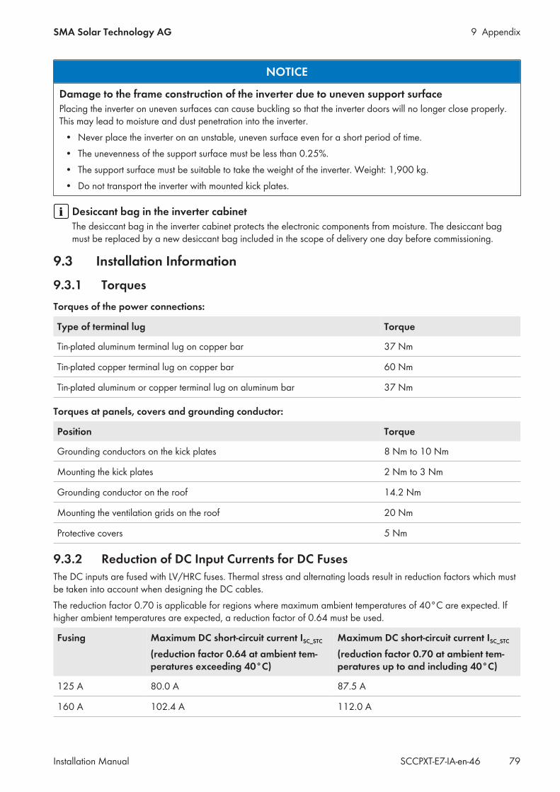
9 AppendixSMA Solar Technology AG
Installation Manual 79SCCPXT-E7-IA-en-46
NOTICE
Damage to the frame construction of the inverter due to uneven support surfacePlacing the inverter on uneven surfaces can cause buckling so that the inverter doors will no longer close properly.This may lead to moisture and dust penetration into the inverter.
• Never place the inverter on an unstable, uneven surface even for a short period of time.• The unevenness of the support surface must be less than 0.25%.• The support surface must be suitable to take the weight of the inverter. Weight: 1,900 kg.• Do not transport the inverter with mounted kick plates.
Desiccant bag in the inverter cabinetThe desiccant bag in the inverter cabinet protects the electronic components from moisture. The desiccant bagmust be replaced by a new desiccant bag included in the scope of delivery one day before commissioning.
9.3 Installation Information
9.3.1 TorquesTorques of the power connections:
Type of terminal lug Torque
Tin-plated aluminum terminal lug on copper bar 37 Nm
Tin-plated copper terminal lug on copper bar 60 Nm
Tin-plated aluminum or copper terminal lug on aluminum bar 37 Nm
Torques at panels, covers and grounding conductor:
Position Torque
Grounding conductors on the kick plates 8 Nm to 10 Nm
Mounting the kick plates 2 Nm to 3 Nm
Grounding conductor on the roof 14.2 Nm
Mounting the ventilation grids on the roof 20 Nm
Protective covers 5 Nm
9.3.2 Reduction of DC Input Currents for DC FusesThe DC inputs are fused with LV/HRC fuses. Thermal stress and alternating loads result in reduction factors which mustbe taken into account when designing the DC cables.The reduction factor 0.70 is applicable for regions where maximum ambient temperatures of 40°C are expected. Ifhigher ambient temperatures are expected, a reduction factor of 0.64 must be used.
Fusing Maximum DC short-circuit current ISC_STC
(reduction factor 0.64 at ambient tem-peratures exceeding 40°C)
Maximum DC short-circuit current ISC_STC
(reduction factor 0.70 at ambient tem-peratures up to and including 40°C)
125 A 80.0 A 87.5 A
160 A 102.4 A 112.0 A
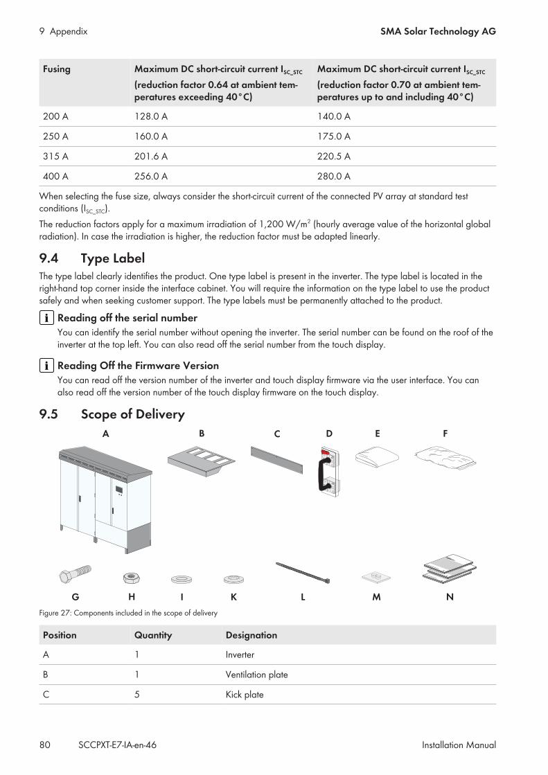
9 Appendix SMA Solar Technology AG
Installation ManualSCCPXT-E7-IA-en-4680
Fusing Maximum DC short-circuit current ISC_STC
(reduction factor 0.64 at ambient tem-peratures exceeding 40°C)
Maximum DC short-circuit current ISC_STC
(reduction factor 0.70 at ambient tem-peratures up to and including 40°C)
200 A 128.0 A 140.0 A
250 A 160.0 A 175.0 A
315 A 201.6 A 220.5 A
400 A 256.0 A 280.0 A
When selecting the fuse size, always consider the short-circuit current of the connected PV array at standard testconditions (ISC_STC).The reduction factors apply for a maximum irradiation of 1,200 W/m2 (hourly average value of the horizontal globalradiation). In case the irradiation is higher, the reduction factor must be adapted linearly.
9.4 Type LabelThe type label clearly identifies the product. One type label is present in the inverter. The type label is located in theright-hand top corner inside the interface cabinet. You will require the information on the type label to use the productsafely and when seeking customer support. The type labels must be permanently attached to the product.
Reading off the serial numberYou can identify the serial number without opening the inverter. The serial number can be found on the roof of theinverter at the top left. You can also read off the serial number from the touch display.
Reading Off the Firmware VersionYou can read off the version number of the inverter and touch display firmware via the user interface. You canalso read off the version number of the touch display firmware on the touch display.
9.5 Scope of Delivery
Figure 27: Components included in the scope of delivery
Position Quantity Designation
A 1 Inverter
B 1 Ventilation plate
C 5 Kick plate

9 AppendixSMA Solar Technology AG
Installation Manual 81SCCPXT-E7-IA-en-46
Position Quantity Designation
D 1 Low-voltage HRC fuse handle (optional)
E 1 Non-woven abrasive
F 1 Desiccant bag
G 68 Screw
H 68 Nut
I 136 Fender washer
K 136 Spring washer
L 80 Cable tie
M 3 Cable support sleeve (9.5 mm to 16 mm)
N 1 Circuit diagram, documentation, report
Position of the LV/HRC fuse handleThe LV/HRC fuse handle is located on the inside of the right-hand interface cabinet door.
9.6 Schematic DiagramSchematic diagrams in PDF format contain jump marks. By double clicking a jump mark, the display will change to thecorresponding current path or the referenced place in the equipment list. Using schematic diagrams in PDF format isrecommended for the installation. The schematic diagrams in PDF format are available on request (see Section 10"Contact", page 82).
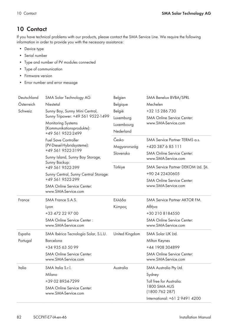
10 Contact SMA Solar Technology AG
Installation ManualSCCPXT-E7-IA-en-4682
10 ContactIf you have technical problems with our products, please contact the SMA Service Line. We require the followinginformation in order to provide you with the necessary assistance:
• Device type• Serial number• Type and number of PV modules connected• Type of communication• Firmware version• Error number and error message
DeutschlandÖsterreichSchweiz
SMA Solar Technology AGNiestetalSunny Boy, Sunny Mini Central,Sunny Tripower: +49 561 9522‑1499Monitoring Systems(Kommunikationsprodukte):+49 561 9522‑2499Fuel Save Controller(PV-Diesel-Hybridsysteme):+49 561 9522-3199Sunny Island, Sunny Boy Storage,Sunny Backup:+49 561 9522-399Sunny Central, Sunny Central Storage: +49 561 9522-299SMA Online Service Center:www.SMA-Service.com
BelgienBelgiqueBelgiëLuxemburgLuxembourgNederland
SMA Benelux BVBA/SPRLMechelen+32 15 286 730SMA Online Service Center:www.SMA-Service.com
ČeskoMagyarországSlovensko
SMA Service Partner TERMS a.s.+420 387 6 85 111SMA Online Service Center:www.SMA-Service.com
Türkiye SMA Service Partner DEKOM Ltd. Şti.+90 24 22430605SMA Online Service Center:www.SMA-Service.com
France SMA France S.A.S.Lyon+33 472 22 97 00SMA Online Service Center :www.SMA-Service.com
ΕλλάδαΚύπρος
SMA Service Partner AKTOR FM.Αθήνα+30 210 8184550SMA Online Service Center:www.SMA-Service.com
EspañaPortugal
SMA Ibérica Tecnología Solar, S.L.U.Barcelona+34 935 63 50 99SMA Online Service Center:www.SMA-Service.com
United Kingdom SMA Solar UK Ltd.Milton Keynes+44 1908 304899SMA Online Service Center:www.SMA-Service.com
Italia SMA Italia S.r.l.Milano+39 02 8934-7299SMA Online Service Center:www.SMA-Service.com
Australia SMA Australia Pty Ltd.SydneyToll free for Australia:1800 SMA AUS(1800 762 287)International: +61 2 9491 4200
10 ContactSMA Solar Technology AG
Installation Manual 83SCCPXT-E7-IA-en-46
United ArabEmirates
SMA Middle East LLCAbu Dhabi+971 2234 6177SMA Online Service Center:www.SMA-Service.com
India SMA Solar India Pvt. Ltd.Mumbai+91 22 61713888
ไทย SMA Solar (Thailand) Co., Ltd.กรงเทพฯ+66 2 670 6999
대한민국 SMA Technology Korea Co., Ltd.서울+82-2-520-2666
South Africa SMA Solar Technology South AfricaPty Ltd.Cape Town08600SUNNY (08600 78669)International: +27 (0)21 826 0600SMA Online Service Center:www.SMA-Service.com
ArgentinaBrasilChilePerú
SMA South America SPASantiago de Chile+562 2820 2101
Other coun-tries
International SMA Service LineNiestetal00800 SMA SERVICE(+800 762 7378423)SMA Online Service Center:www.SMA-Service.com
www.SMA-Solar.com