Installation Manual SEARCHLIGHT SONAR CH-250 · i WARNING ELECTRICAL SHOCK HAZARD Do not open the...
83
SAFETY INSTRUCTIONS....................... i SYSTEM CONFIGURATION ................. iii EQUIPMENT LISTS .............................. iv 1. Mounting............................................ 1 1.1 Monitor Unit/Control Unit.........................1 1.2 Transceiver Unit......................................6 1.3 Hull Unit..................................................9 1.4 Interface Unit ........................................ 21 1.5 Motion Sensor MS-100 (option) ............ 22 2. Wiring .............................................. 23 2.1 Wiring among Units .............................. 23 2.2 Transceiver Unit.................................... 26 2.3 Hull Unit................................................ 29 2.4 Interface Unit ........................................ 30 3. ADJUSTMENTS ............................... 31 3.1 General Checks ................................... 31 3.2 TX Frequency Checking....................... 32 3.3 Heading Adjustment/Soundome Setting ....................................................... 34 3.4 Adjustment of Motion Sensor ............... 37 3.5 System Back Up .................................. 38 3.6 Setting of Interface Unit........................ 40 Input/Output Description.................... 41 PACKING LISTS................................. A-1 OUTLINE DRAWINGS........................ D-1 INTERCONNECTION DIAGRAMS..... S-1 Installation Manual SEARCHLIGHT SONAR CH-250
Transcript of Installation Manual SEARCHLIGHT SONAR CH-250 · i WARNING ELECTRICAL SHOCK HAZARD Do not open the...

SAFETY INSTRUCTIONS....................... i
SYSTEM CONFIGURATION................. iii
EQUIPMENT LISTS .............................. iv
1. Mounting............................................ 1
1.1 Monitor Unit/Control Unit.........................1
1.2 Transceiver Unit......................................6
1.3 Hull Unit..................................................9
1.4 Interface Unit ........................................21
1.5 Motion Sensor MS-100 (option) ............22
2. Wiring .............................................. 23
2.1 Wiring among Units ..............................23
2.2 Transceiver Unit....................................26
2.3 Hull Unit................................................29
2.4 Interface Unit ........................................30
3. ADJUSTMENTS ...............................31
3.1 General Checks................................... 31
3.2 TX Frequency Checking....................... 32
3.3 Heading Adjustment/Soundome Setting
....................................................... 34
3.4 Adjustment of Motion Sensor ............... 37
3.5 System Back Up .................................. 38
3.6 Setting of Interface Unit........................ 40
Input/Output Description....................41
PACKING LISTS................................. A-1
OUTLINE DRAWINGS........................ D-1
INTERCONNECTION DIAGRAMS..... S-1
Installation ManualSEARCHLIGHT SONAR CH-250

Your Local Agent/DealerYour Local Agent/Dealer
9-52 Ashihara-cho,9-52 Ashihara-cho,Nishinomiya, JapanNishinomiya, Japan
Telephone :Telephone : 0798-65-21110798-65-2111faxfax 0798-65-42000798-65-4200::
FIRST EDITION :FIRST EDITION : MAR.MAR. 20002000Printed in JapanPrinted in JapanAll rights reserved.All rights reserved.KK :: NOV.NOV. 20,200320,2003
PUB.No.PUB.No. IME-13160-KIME-13160-K*00080895001**00080895001**00080895001**00080895001*(( HIMAHIMA )) CH-250CH-250
* 0 0 0 8 0 8 9 5 0 0 1 ** 0 0 0 8 0 8 9 5 0 0 1 *
*IME13160K00**IME13160K00**IME13160K00**IME13160K00*
* I M E 1 3 1 6 0 K 0 0 ** I M E 1 3 1 6 0 K 0 0 *

i
WARNINGELECTRICAL SHOCK HAZARDDo not open the equipment.
Only qualified personnelshould work inside theequipment.
Be sure no water leaks in at the transdu-cer installation site.
Water leakage can sink the vessel. Also confirm that the transducer will not loosen by ship's vibration. The installer of the equipment is solely responsible for the proper installation of the equipment. FURUNO will assume no responsibility for any damageassociated with improper installation.
WARNING
If a steel tank is installed on a wooden or FRP vessel, take appropriatemeasures to prevent electrolyticcorrosion.
Electrolytic corrosion can damage the hull.
Be sure that the power supply is compatible with the voltage rating ofthe equipment.
Connection of an incorrect power supply can cause fire or equipment damage.The voltage rating of the equipment appearson the label above the power connector.
Turn off the power at the switchboardbefore beginning the installation.
Fire or electrical shock can result if the power is left on.
Do not install the equipment where itmay get wet from rain or water splash.
Water in the equipment can result in fire,electrical shock or equipment damage.
Installe the specified transducer tankin accordance with the installation instructions. If a different tank is to beinstalled the shipyard is solely respon-sible for its installation, and it should be installed so the tank doesn't strike an object.
The tank or hull may be damaged if the tank strikes an object.
SAFETY INSTRUCTIONS

ii
CAUTION
Observe the following compass safedistances to prevent deviation of amagnetic compass:
Ground the equipment toprevent electrical shock andmutual interference.
Monitor unit/Control unit
Transceiverunit
Interfaceunit
Standard Steering
0.80 m 0.55 m
0.50 m 0.35 m
0.95 m 0.65 m
WORKING WITH THE SONAROIL
PrecautionsKeep oil away from eyes. Wear protectivegloves when working with the oil. The oilcan cause inflammation of the eyes.
Do not touch the oil. Wear protectivegloves when working with the oil. The oilcan cause inflammation of the skin.
Do not ingest the oil. Diarrhea or vomiting can result.
Keep the oil out of reach of children.
EmergencyIf the oil enters eyes, flush with cleanwater about 15 min. Consult a physician.
If the oil contacts skin, wash within soap and water.
If the oil is ingested, see a physicianimmediately.
Disposal of oil and its containerDispose of oil and its container inaccordance with local regulations. For further details, contact place ofpurchase.
StorageSeal container to keep out foreignmaterial. Store in dark place.
CAUTION
Install the monitor unit MU-100C out ofdirect sunlight.
It is difficult to see the display in direct sunlight.
Turn the main power off before this check,otherwise the raise/lower motor action may cause injurely

iii
SYSTEM CONFIGURATION
HULL UNIT
SPEAKERDATA/VIDEO OUT
MOTION SENSOR
12-32 VDC
Note 1
Note 2
12-32 VDCSpeaker
Motion Sensor
VGA Ext.Monitor
Control Unit
DisplayUnit
CONTROL UNIT CH-252
Remote Controller
HULL UNIT CH-254/255
12/24-32 VDC
Navigator
Note 2MONITOR UNIT MU-100C
Note 1: MU-100C is the standard supplydisplay unit. An external monitormay be connected via theinterface unit (option). The drawingabove shows the system configurationwith the MU-100C.
Note 2: For blackbox type, MU-100C isnot supplied. Connect externalmonitor (user supply) and control
unit to the interface unit.
TRANSCEIVER UNIT CH-253
INTERFACE UNIT IF-8000

iv
EQUIPMENT LISTS
Standard Supply Name Type Code no. Qty Remarks Control Unit/ Monitor Unit
CH-252/ MU-100C
1 Not supplied with blackbox type
Control Unit CH-252 1 Not supplied with unibody type Interface Unit IF-8000 1 For blackbox type Transceiver Unit CH-253 1
CH-254 400 stroke Hull Unit CH-255
1 250 stroke
See the following table for Hull Unit Standard Supply.
SP06-01100 000-068-488 For unibody type, SP06-01102*, SP06-01103*
SP06-01110 000-068-489
1
For blackbox type, SP06-01102*, SP06-01111*, SP06-01103*
Spare Parts
SP06-01101* 006-556-200 For unibody type Installation Materials
1 CP06-01251* and two cables (page viii)
FP02-05100 000-012-474 For unibody type, FP02-05101*, FP06-01102*
Accessories
FP06-01120* 006-556-260
1
For control unit
*: See the lists at the back of this manual.

v
Hull Unit (1) Spec. Code no. Type Stroke Power Frequency Shaft Cable
000-068-515 CH-254-1-60-22-35 60 kHz 000-068-516 CH-254-1-88-22-35 88 kHz 000-068-517 CH-254-1-150-22-35 150 kHz 000-068-518 CH-254-1-180-22-35 180 kHz 000-068-519 CH-254-1-240-22-35 240 kHz
2.2 m 3.5 m
000-068-559 CH-254-1-60-22-52 60 kHz 000-068-560 CH-254-1-88-22-52 88 kHz 000-068-561 CH-254-1-150-22-52 150 kHz 000-068-562 CH-254S-1-180-22-52 180 kHz 000-068-563 CH-254S-1-240-22-52 240 kHz
2.2 m 5.2 m
000-068-520 CH-254-1-60-38-52 60 kHz 000-068-521 CH-254-1-88-38-52 88 kHz 000-068-522 CH-254-1-150-38-52 150 kHz 000-068-523 CH-254S-1-180-38-52 180 kHz 000-068-524 CH-254S-1-240-38-52
12 V
240 kHz
3.8 m 5.2 m
000-068-525 CH-254-2-60-22-35 60 kHz 000-068-526 CH-254-2-88-22-35 88 kHz 000-068-527 CH-254-2-150-22-35 150 kHz 000-068-528 CH-254S-2-180-22-35 180 kHz 000-068-529 CH-254S-2-240-22-35 240 kHz
2.2 m 3.5 m
000-068-564 CH-254-2-60-22-52 60 kHz 000-068-565 CH-254-2-88-22-52 88 kHz 000-068-566 CH-254-2-150-22-52 150 kHz 000-068-567 CH-254S2-180-22-52 180 kHz 000-068-568 CH-254S-2-240-22-52 240 kHz
2.2 m 5.2 m
000-068-530 CH-254-2-60-38-52 60 kHz 000-068-531 CH-254-2-88-38-52 88 kHz 000-068-532 CH-254-2-150-38-52 150 kHz 000-068-533 CH-254S-2-180-38-52 180kHz 000-068-534 CH-254S-2-240-38-52
400 mm
24 V-32 V
240 kHz
3.8 m 5.2 m
000-068-535 CH-255-1-60-22-35 60 kHz 000-068-536 CH-255-1-88-22-35 88 kHz 000-068-537 CH-255-1-150-22-35 150 kHz 000-068-538 CH-255S-1-180-22-35 180 kHz 000-068-539 CH-255S-1-240-22-35 240 kHz
2.2 m 3.5 m
000-068-540 CH-255-1-60-38-52 60 kHz 000-068-543 CH-255-1-88-38-52 88 kHz 000-068-544 CH-255-1-150-38-52 150 kHz 000-068-547 CH-255S-1-180-38-52 180 kHz 000-068-548 CH-255S-1-240-38-52 240kHz
3.8 m 5.2 m
000-068-569 CH-255-1-60-22-52 60 kHz 000-068-570 CH-255-1-88-22-52 88 kHz 000-068-571 CH-255-1-150-22-52 150 kHz 000-068-572 CH-255S-1-180-22-52 180 kHz 000-068-573 CH-255S-1-240-22-52
12 V
240 kHz
2.2 m 5.2 m
000-068-549 CH-255-2-60-22-35 60 kHz 000-068-550 CH-255-2-88-22-35 88 kHz 000-068-551 CH-255-2-150-22-35 150 kHz 000-068-552 CH-255S-2-180-22-35 180 kHz 000-068-553 CH-255S-2-240-22-35 240 kHz
2.2 m 3.5 m
000-068-554 CH-255-2-60-38-52 60 kHz 000-068-555 CH-255-2-88-38-52 88 kHz 000-068-556 CH-255-2-150-38-52 150 kHz 000-068-557 CH-255S-2-180-38-52 180 kHz 000-068-558 CH-255S-2-240-38-52 240 kHz
3.8 m 5.2 m
000-068-574 CH-255-2-60-22-52 60 kHz 000-068-575 CH-255-2-88-22-52 88 kHz 000-068-576 CH-255-2-150-22-52 150 kHz 000-068-577 CH-255S-2-180-22-52 180 kHz 000-068-578 CH-255S-2-240-22-52
250 mm
24 V-32 V
240 kHz
2.2 m 5.2 m

vi
Hull Unit Standard Supply Name Type Code no. Qty Remarks
CH-2541 - Raise/lower Drive Unit CH-2551 -
1 set
Soundome CH-2542 - 1 set See the following Soudome table.
Flange CH-2543 006-557-810 1 set Flange, grease cotton Assembly Kit for field
CH-2544 006-557-820 1 set Shaft, retraction tank, seal, adhesives, tank guide, material box
SHJ-0006-1 661-000-061 2.2 m, for 3.5/5.2 m cable Shaft 06-007-1572-0 600-715-720
1 3.8 m, for 5.2m cable
Sonar Oil 4 lit. 000-824-033 1

vii
Shaft parts Name Type Code no. Qty Remarks Pipe cap SHN-0011-0 661-400-110 1 Jubilee Clip 1X28-41 000-801-857 1 Hex. bolt M10X35 SUS304 000-862-175 2 U-nut M10 SUS304 000-863-930 2 Flat washer M10 SUS304 000-864-131 4
Tank parts Name Type Code no. Qty Remarks Hex. bolt M20X80 SUS304 000-801-893 8 Hex. nut M20 SUS304 000-863-116 16 Flat washer M20 SUS304 000-864-136 16 Spring washer M20 SUS304 000-864-270 8
Adhesives Name Type Code no. Qty Remarks Kinolastar 855 000-801-328 1 Anti-corrosion Three Bond 1104 000-854-104 1 Sealant, 200g Cemedine High Super 6G 000-856-520 1 adhesive
Tank guide Name Type Code no. Qty Remarks Tank guide CH-2544 006-557-200 1
Assembly kit for field (Material Box) Name Type Code no. Qty Remarks Socket set screw TWB-40 000-804-423 1 4 mm Shim (0.5) 06-021-4035 100-295-420 2 0.5 mm Shim (1.0) 06-021-4036 100-295-430 2 1.0 mm Shim (2.0) 06-021-4037 100-295-440 4 2.0 mm

viii
Cables for Installation materials Code no. Specification (Cable between unit) Type Monitor unit (or IF)
and Transceiver unit Transceiver unit and Hull unit Crimp-on lug
CP06-01200 000-068-496 06S4080*15m* CP06-01251* CP06-01201 000-068-497 06S4080*30m* CP06-01251* CP06-01202 000-068-498
06S4078*5m*
06S4080*50m* CP06-01251* CP06-01203 000-068-499 06S4080*15m* CP06-01251* CP06-01204 000-068-500 06S4080*30m* CP06-01251* CP06-01205 000-068-502
06S4078*10m*
06S4080*50m* CP06-01251*
Control unit cable
Type Code no. Qty Remarks
CP02-06600* 000-012-486 1 MJ-A10SPF0002-0015, for unibody type
CP02-06610* 000-012-480 MJ-A10SPF0002-015, 1.5 m CP02-06620* 000-012-481
1 MJ-A10SPF0002-050, 5 m
For blackbox type
*: See lists at the back of this manual.
Options Name Type Code no. Qty Remarks Remote Controller CH-256-E 000-068-492 1 set Interface Unit IF-8000 000-068-495 1 set Motion Sensor MS-100 - 1 set Speaker SC-05WR 000-136-156 1 Signal Cable S06-9-5 006-556-270 1 Extension cable for speaker
MJ-A6SSPF0012-050 000-134-424 6pin-6pin, 5m MJ-A6SSPF0012-100 000-133-817 6pin-6pin, 10m MJ-A6SSPF0011-050 000-132-244 6pin-4pin, 5m
Cable assy.
MJ-A6SSPF0011-100 000-132-336
1
6pin-4pin, 10m OP06-15-1.5 006-556-280 For desktop, with 1.5 m OP06-15-5 006-556-290
1 For desktop, with 5 m
OP02-83-1.5 001-413-600 1 For flush mount, with 1.5 m cable
Control Unit Separate Kit
OP02-83-5 001-413-610 1 For flush mount, with 5m cable OP06-16 006-556-300 1 For unibody type Flush mount kit OP06-17 006-556-310 1 For separate type display unit
Control unit flush mount kit
OP06-18 006-556-320 1
Rectifier RU-1746B-2 000-030-439 1 06-007-1570-1 600-715-701 1 Steel, 1m SHJ-0001-1 661-000-011 1 Steel, 1.8m 06-007-1571-1 600-715-711 1 Steel, 3.5m SHJ-0022 661-000-220 1 FRP, 1m 06-007-1573-0 600-715-730 1 FRP, 1.8m
Tank
OP10-5 000-069-763 1 Aluminum, 1m

1
1. Mounting
1.1 Monitor Unit/Control Unit This searchlight sonar has two types of shipment, standard type which is shipped with monitor unit and blackbox type which is shipped without monitor unit, but has interface unit. For blackbox type, see page 4.
The control unit can be installed together with the monitor unit, or independently of the monitor unit. On installing separately, the optional monitor kit is required. These units can be installed on a tabletop or flush mounted in a console or panel.
1.1.1 General mounting considerations • Keep the monitor unit out of direct sunlight.
• Select a location where the unit(s) can easily be operated while observing the fishing ground or area surrounding the vessel.
• For maintenance and checking purposes, leave sufficient space at the sides and rear of the unit and leave slack in cable. (Refer to the outline drawing at the back of this manual.)
• A magnetic compass will be affected if place too close to the monitor unit. Observe the following compass safe distance to prevent deviation to a magnetic compass: Standard compass: 0.80 m, Steering compass: 0.55 m.
1.1.2 Mounting method of monitor unit (Standard type) 1. Fasten the mounting base to the mounting location with four tapping screws.
FRONT
Mounting base
2. For unibody mounting; a) Fasten the bracket at the rear of monitor and control units with four binding screws (M4x10).
2
11 22
33
4
4
Bracket (rear view)
Bracket, rear view
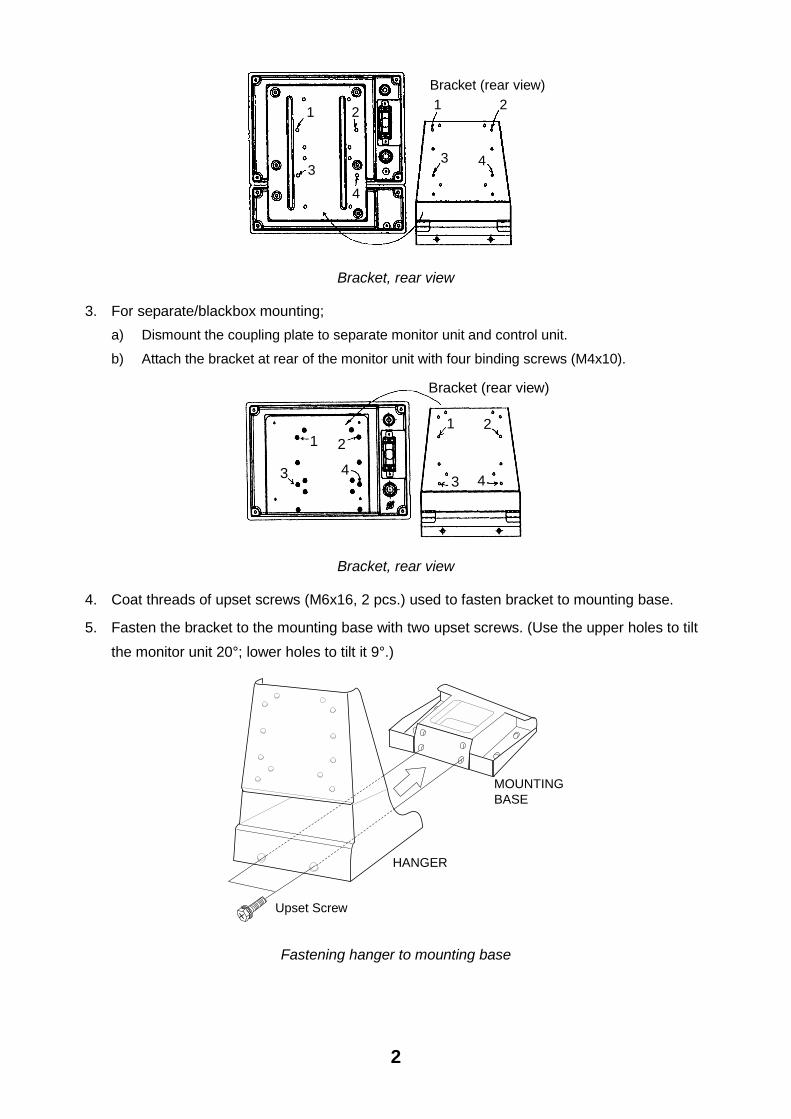
3. For separate/blackbox mounting; a) Dismount the coupling plate to separate monitor unit and control unit.
b) Attach the bracket at rear of the monitor unit with four binding screws (M4x10).
1 2
3 4
1 2
3 4
Bracket (rear view)
Bracket, rear view
4. Coat threads of upset screws (M6x16, 2 pcs.) used to fasten bracket to mounting base.
5. Fasten the bracket to the mounting base with two upset screws. (Use the upper holes to tilt the monitor unit 20°; lower holes to tilt it 9°.)
Upset Screw
HANGER
MOUNTINGBASE
Fastening hanger to mounting base

3
Flush mounting
Flush mounting for unibody (Type: OP06-16, Code no.: 006-556-300)
Name Type Code No. Qty Remarks Fixing metal 06-021-1311 100-279-610 1 Tapping screw 5X20 000-802-840 6 Hex. bolt M4X12 000-882-040 4
1. Make holes at the place to mount (W287 X H297).
2. Fasten monitor and control units with the fixing metal (supplied as option) and four hex. bolts (supplied as option).
3. Fasten the fixing metal assembled at step 2 to holes made at step 1 with six tapping screws (supplied as option).
Hex. Bolts
Fixing metal
Flush mounting for monitor unit (Type: OP06-17, Code no. 006-556-310)
Name Type Code No. Qty Remarks Fixing metal 06-021-1321 100-279-621 1
Tapping screw 5X20 000-802-840 4
Hex. bolt M4X12 000-882-040 4
1. Make holes at the place to mount (W287 X H207).
2. Fasten the fixing metal (supplied as option) to the monitor unit with four hex. bolts (M4x12, supplied as option).
3. Fasten the fixing metal assembled at step 2 to holes made at step 1 with four tapping screws (5x20, supplied as option).

4
Hex. Bolts
Fixing Metal
Flush mounting for control unit Type: OP02-83-1.5, Code no.: 001-413-600 (1.5 m cable) OP03-83-5, Code no.: 001-413-610 (5m cable)
Name Type Code No. Qty Remarks Fixing metal 06-021-2101 100-279-731 1 Tapping screw 5X20 000-802-840 4 Hex. bolt M4X12 000-882-040 2
MJ-A10SPF0002-015
000-142-878 1 1.5 m Cable assembly
MJ-A10SPF0002-050
000-131-411 1 5 m
Select one.
1. Make holes at the place to mount (W287 X H87).
2. Fasten the fixing metal to the control unit with two hex. bolts (supplied as option).
3. Fasten the fixing metal assembled at step 2 to holes made at step 1 with four tapping screws (supplied as option).
Hex. Bolts
Fixing metal
1.1.3 Blackbox type The blackbox type is required to connect a standard VGA monitor via the interface unit IF-8000. Supply monitor and interconnection cable (Max. length 15 m with Dsub-15P connectors of male, three rows of 15 pins) locally. The monitor used should satisfy the specifications shown below.
• VGA type
• ANALOG RGB 0.7 Vpp, positive polarity
• TLL level H, V, Negative polarity

5
1.1.4 Control unit On blackbox type, fix the control unit to the mounting plate (supplied as accessories). See the parts list of FP06-01120 and outline drawings at the back of this manual.
1. Fix the mounting plate to the place selected with two tapping screws (5X20, supplied).
2. Fix the bracket to the control unit with two hex. screws (M4X12, supplied).
3. Insert the screw driver from the top of the mounting plate holes and then tighten two hex. screws (M4X12) loosely.
4. Attach the control unit to the mounting plate, and fasten two hex. screws tightly.
5. Attach two cosmetic caps to holes at the top of the mounting plate.
Cable entrance holeMounting plate
Cable
Tapping screws (5X20)
Fasten the screws to fix the bracket.
Bracket
Bracket
Insert to the hex. screws tightened at step 3.
Cable can be passed this direction.
On mounting the control unit separate from the monitor unit, the optional control unit separate kit is required. Mount the control unit same as the above procedure. See the outline drawing at the back of this manual to mount.
Type: OP06-15-1.5 Code no.: 006-556-280: with 1.5 m cable Type: OP06-15-5 Code no.: 006-556-290: with 5 m cable
Name Type Code no. Qty Remarks MJ-A10SPF0002-015 000-142-878 For 1.5 m cable Cable MJ-A10SPF0002-050 000-131-411
1 For 5 m cable
Bracket 06-021-2112 100-281-880 1 Mounting Plate 06-021-2111 100-279-740 1 Tapping Screw 5X20 000-802-081 2 Cosmetic Cap DP-687 000-808-417 2 Hex. Screw M4X12 000-882-040 4 Bind Screw M4X10 000-807-331 4 For monitor

6
1.2 Transceiver Unit
1.2.1 General mounting considerations • The mounting location should be well ventilated and dry.
• The unit can be mounted on bulkhead or the deck.
• Secure the maintenance space shown in drawing below for ease of maintenance and service.
• The maximum cable length between the transceiver unit and the raise/lower drive unit cable is 50 m.
• The maximum cable length between the transceiver unit and the monitor (interface) unit is 10 m.
1.2.3 Mounting method Fasten the transceiver unit with four tapping screws (5X20, local supplied).
For bulkhead mounting, tighten upper tapping screws so there is 5 mm clearance between bottom of screw head and bulkhead, and screw slots of the unit. Then fasten lower screws.
1.3 Hull Unit
1.3.1 General mounting considerations • Noise and air bubbles will affect performance.
• Do not turn on the equipment with the transducer exposed to air. Exposing the transducer to air may damage it.
1.3.2 Installation position considerations Discussion and agreement are required with the dockyard and ship owner in deciding the location for the hull unit. When deciding the location, take into account the following points:
• Select an area where propeller noise, cruising noise, bubbles and interference from turbulence are minimal. Generally, the point at 1/3 to 1/2 of the ship’s length from the bow or near the keel is the best. On-the-keel installation is advantageous for minimizing oil consumption in comparison with of-the-keel. If the hull unit cannot be installed on the keel, the center of the retraction tank should be within 1 meter of the keel to prevent a rolling effect.

7
Wealding bead
Wealding bead
1/2 1/3 Within 1 meter
Installation location for hull unit
• Select a place where interference from the transducers of other sounding equipment is minimal. The hull unit should be at least 2.5 meters away from the transducers of other sounding equipment.
• An obstacle in the fore direction not only causes a shadow zone but also aerated water, resulting in poor sonar performance. Be sure to locate the transducer well away from any obstacle in the fore direction.
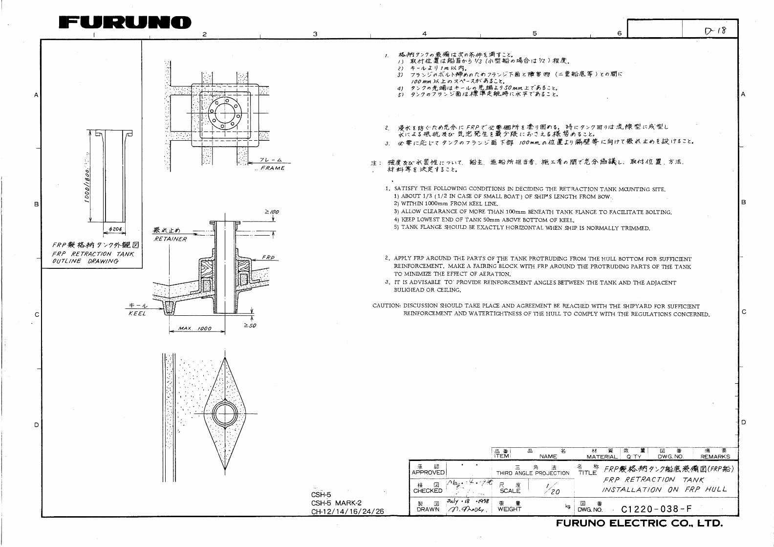
Mounting method A typical mounting method is shown in the outline drawing at the back of this manual. Consult ship’s owner, dockyard and user to determine appropriate mounting method. Pay attention to safety (strength, watertightness) first, followed by ease of maintenance and inspection.
1.3.3 Transducer tank
Tank length
Shorten the transducer tank so the transducer is lowered into water as deep as possible. Pay particular attention to the tank length Lt. Determine the length of the main shaft.
• Length of main shaft = Lt + 200 mm (for 400 stroke)
• Length of main shaft = Lt + 50 mm (for 250 stroke)
Note : When the retraction tank is constructed locally, finish it so that welding beads do not protrude on the inner surface of the tank. The tank guide will hit the bead, burning out the raise/lower motor. Also, do not position the welding bead in the ship’s fore-aft line.

8
For small FRP ship
For small FRP ship retraction tank should be 2 degrees against ship’s draft. Therefore, this creates high water pressure in the tank because of the resistance at the rear of the tank well. To solve this problem, attach a fin to the hull at the location shown in figure below.
Retraction dome
Fin
Bottom of ship
This fin makes a smooth stream in the retraction dome. Attach the fin (height:1-1.5 cm, FRP).
Mounting of transducer tank
Install the transducer tank referring to the hull unit outline drawings at the back of this manual.
Note 1: When making a retraction tank locally, the inside diameter of the retraction tank should not be more than φ190±0.5 as shown on outdrawing at the back of this manual. If larger, the hull unit may be danger.
Note 2: Locate the retraction tank so that the center of any two bolt holes is facing the ship’s bow.
Bow
a=b
ab

9
1.3.4 Assembling and mounting of hull unit The hull unit is shipped as the parts shown in the hull unit kit on Equipment Lists (page iv and after). Assemble the hull unit as shown in the procedure below.
Necessary tools
Name Specification Remarks Wrench For M10 (Hex. size 17 mm) Recommended: double offset
wrench
Wrench For M20 (Hex. size 20 mm) Pipe Wrench 55 mm For fixing gland Ball Wrench Hex size 4 mm For fixing the dome
1. Calculate necessary length of main shaft from the length of retraction tank Lt and cut off the spare portion. When 1 m or 1.8 m long tank is used, main shaft (1.17 m or 1.97 m) can be used without cutting off any portion.
Supplied length: 2.2 m or 3.8 m
Lt + 200 mm for 400 mm strokeLt + 50 mm for 250 mm stroke
Take care not to damage.
Chamfer the edge toprotect O-ring from damage.
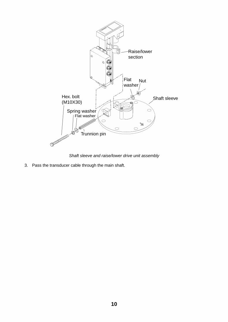
2. Remove hex bolt, nut, spring washers, flat washers and trunnion pins from the main body flange. And then, mount the raise/lower drive unit on the shaft sleeve by using the hardware removed.
10
WARNING
WARNING
Hex. bolt (M10X30)
Spring washerFlat washer
Flat washer
Nut
Trunnion pin
Raise/lowersection
Shaft sleeve
Shaft sleeve and raise/lower drive unit assembly
3. Pass the transducer cable through the main shaft.

11
4. Fully screw main shaft into the soundome neck, and then unscrew by four turns. Coat threads with adhesive (HIGH SUPER).
Main Shaft
Grasp the soundome neck with a wrench,and tighten the shaft with a pipe wrench.
Coat threads with adhesive (HIGH SUPER).
Applying Adhesive (HIGH SUPER) to main shaft
5. Screw in main shaft completely.
6. As shown in the drawing below, confirm that the narrowest gap between the tank guide, and retraction tank in the range (20 to 170 mm) is within 0.5 mm.
Tank guide
Retraction tank
less than 0.5mm
20 mm (400 stroke) - 170 mm (250 stroke)
Slide range(Stroke) 250 or 400
Tank and tank guide, sectional view

12
7. If the gap at a side is more than 0.5 mm, install a shim to make the gap within 0.5 mm.
a) Unscrew four M10x50 bolts.
b) Unscrew four countersunk screws, then attach the shim with the countersunk screws as shown below.
Hex. bolt(M10X50)
Flat washer
Nut
Flat washer
Spring washer
Countersunk screw(M4x16)
Guide plate
Shim (1.0)
Shim (1.5)
Hex. bolt(M10x70)
Installing shims

13
The table below shows tank length and necessary shim thickness. In addition, the shim thickness shown is for one side. For example, when cutting the 1800 mm tank to 800 mm, the tank inside diameter is 191.25 mm, shim thickness is 2.5 mm as shown the table in below.
0
200
400
600
800
1000
1200
1400
1600
1800
189 190 191 192 193 194
Tank inside dia. Φ B (mm)
Leng
th A
(mm
) tan
k sh
orte
ned
0
1
2
3
4
5
6
7
8
Shim
thic
knes
s (m
m)
For 1 m tank
For 1.8 m tank
Shim thickness
The table below shows number of shims required and shim thickness.
Shim thickness 0 0.5 1 1.5 2 2.5 3 3.5 4 4.5 5 5.5 6 6.5t2.0 1 1 1 1 2 2 2 2 2 2t1.0 1 1 1 1 1 1 2 2t0.5 1 1 1 1 1 1 1
Inside dia of tank 188.1 188.7 189.3 189.9 190.5 191.1 191.7 192.3 192.9 193.5 194.1 194.7 195.3 195.9
14
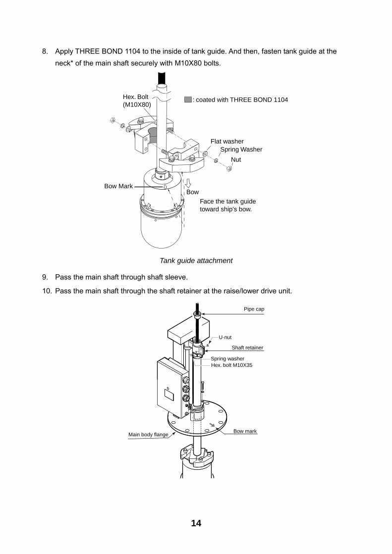
8. Apply THREE BOND 1104 to the inside of tank guide. And then, fasten tank guide at the neck* of the main shaft securely with M10X80 bolts.
Bow MarkBow
Hex. Bolt (M10X80)
Nut
Spring WasherFlat washer
Face the tank guide toward ship's bow.
: coated with THREE BOND 1104
*
Tank guide attachment
9. Pass the main shaft through shaft sleeve.
10. Pass the main shaft through the shaft retainer at the raise/lower drive unit.
Pipe cap
Shaft retainer
Main body flangeBow mark
Spring washerHex. bolt M10X35
U-nut

15
11. Face the bow mark on the soundome with the bow mark on the shaft sleeve, and then fix the main shaft with and shaft retainer.
12. Fix the jubilee clip to the main shaft.
15 mm
1-2 mm
Main shaft
Jubilee Clip
Hex. bolt
Shaft retainer
Note: Attach the shaft retainer so it is 15 mm from the top of the shaft. The soundome is then placed 10 mm above the bottom of tank when retracted.
13. Insert grease cotton (supplied with shaft sleeve), and fix them with the cotton retainer as follows.
a) Wind grease cotton onto main shaft.
b) Mark on the cotton as below.
c) Remove the cotton from the shaft, and then cut it at the position of the mark. Discard the ends.
d) Wind cottons as shown below.
e) Push cottons into the main body flange.
f) Tighten the grease cotton retainer.
Wind grease cottononto main shaft andcut it as shown below.
Space joints of grease cotton 120 apart and push them into body flange.
Spring washer
Cotton retainer
Installing grease cotton on the main shaft
14. Fasten the pipe cap (supplied) to main shaft.
15. Unscrew 10 pcs of M5X35 socket head cap screws with soundome fixing tool to separate soundome.

16
Protection sponge
Rotate 4 or 5 turns by hand to make sure that turning mechanisms are functioning properly.
O-ring
Remove.
Socket head cap screw10pcs, M5X35
Spring washer
Soundome
Apply KINORUSTER.
Detaching the soundome
16. Throw away protection sponge placed in soundome.
17. Stand the soundome upright on top of the soundome packing. Fill the soundome with oil (supplied) so the level is 5 cm on the top of the soudome. Keep the soundome packing for future use.
Sonar oil
Stand the soundome upright on top the soundome packing.
Ball wrench
5 cm
Filling the soundome with sonar oil

17
CAUTIONKeep oil away from eyes. Where protective goggles when working with the oil. The oil cause inflammation of the eyes.Do not touch the oil. The oil can cause inflammation of the skin. Wear protectivegloves when working with the oil.Do not ingest the oil. Diarrhea or vomitingcan result.Keep the oil out of reach of children.
EMERGENCYIf the oil enters the eyes, flush with cleanwater about 15 minutes. Consult a physician. If oil contacts skin, wash with soap and water. If the oil is ingested, see a physician immediately.
DISPOSAL OF OIL AND ITS CONTAINERDispose of oil and its container in accordance with local regulations. For further information,contact place of purchase.
STORAGESeal container to keep out foreign material.Store in dark place.
18. Rotate the transducer manually as shown angle in below, and then refit soudome.
Transducer
Soundome
.
Note 1: Do not lay the oil-filled soundome for five minutes. Oil may leak.

18
When the soundome is painted to keep marine life off the transducer, observe the following
precautions:
• Use only anti-fouling paint type MARINE STAR 20 (Manufacture: Chugoku Marine Paint Co., Ltd., Japan).
• Paint only the plastic portion of the dome. Painting the metal parts causes corrosion.
Paint area
19. Clean surface of gasket, tank flange and shaft sleeve, and then apply THREE BOND 1104 to flange gasket.
20. Apply a slight coat of KINORUSTER to bolts, nuts and washers.
21. Set the hull unit into the retraction tank, taking care not to damage soundome.
Spring washer
Flat washer
Spring washerFlat washer
Nut
Hex. bolt M10X35
Hex. bolt M20X80
Shaft retainer
Flange gasket
Retraction tankflange
Shaft sleeve
U-nut
Bow mark

19
22. Fix the shaft sleeve and retraction tank with hex bolts, flat washers and spring washers.
10 mm
15 mm
1-2 mm
Bow
Main shaft
Jubilee clip
Hex bolt
Shaft retainer
20
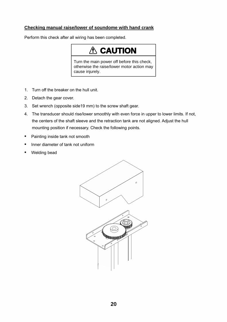
Checking manual raise/lower of soundome with hand crank
Perform this check after all wiring has been completed.
CAUTIONTurn the main power off before this check, otherwise the raise/lower motor action may cause injurely.
1. Turn off the breaker on the hull unit.
2. Detach the gear cover.
3. Set wrench (opposite side19 mm) to the screw shaft gear.
4. The transducer should rise/lower smoothly with even force in upper to lower limits. If not, the centers of the shaft sleeve and the retraction tank are not aligned. Adjust the hull mounting position if necessary. Check the following points.
• Painting inside tank not smooth
• Inner diameter of tank not uniform
• Welding bead

21
1.4 Interface Unit For the blackbox type, the interface unit is shipped as standard.
1.4.1 General mounting considerations • The mounting location should be well ventilated and dry, avoiding splay or rain.
• The unit can be mounted on a bulkhead or the deck.
• Secure the maintenance space shown in drawing below for ease of maintenance and service.
• The maximum cable length between the interface unit and the transceiver unit is 10 m.
Externalmonitor
Transceiverunit
Externalmonitor
Monitor unitMU-100C
InterfaceunitA
CA
B
06S4078
06S4078
06S4078
06S4078
Externalmonitor
Transceiverunit
Interfaceunit
Interfaceunit
A+B 15m<=
A+C 15m<=
1.4.2 Mounting method Fasten the interface unit with four tapping screws (5X20, local supplied).
For bulkhead mounting, tighten upper tapping screws so there is 5 mm clearance between bottom of screw head and bulkhead, and screw slots of the unit. Then fasten lower screws.

22
1.5 Motion Sensor MS-100 (option) The MS-100 measures ship�s pitching and rolling angles with sensor using the principles of the gyroscope. The MS-100 is free from error caused by ship�s vertical and horizontal motion. Therefore, it can be installed at any convenient location. However, ship�s semi-permanent inclination due to loading imbalance cannot be detected. Compensate for this as described in Chapter 3.
1.5.1 Mounting considerations • Vibration in the mounting area should be minimal.
• Locate the unit away from areas subject to water splash.
• The ambient temperature should not exceed 50 °C
1.5.2 Mounting procedure Orient the FORE mark on the unit toward the ship�s bow and mount the unit level to within 5° in all direction. For the offset, see Chapter 3.
FORE
AFT
θ ≤ 5°

23
2. Wiring
2.1 Wiring among Units • The figure on the next page shows wiring among units.
• The signal cables are fitted with connectors. Connect the cables to the display, transceiver and hull units referring to the interconnection diagram and the drawing on page S-1.
• The power cable should be arranged locally. Use power cable type DPYCYS-2.5 (Japan Industrial Standard cable) or equivalent cables. Attach climp on lugs as shown below.
40 5
50Vinyl sheath Braided shield
FV2-4(blue)
Armor
Conductor
Insulator
Inclusion
Tape
Braided shield
SheathArmor
Vinyl sheathS = 2.5 mm =15.2 mm
2
• The raise/lower drive motor and breaker are different depending on ship�s mains.
• Install the main switch for the sonar where it can be easily accessed. Turn off this switch when the sonar is not being used, to reduce power consumption and to prevent the transducer from slipping by vibration.
• If D-sub connector is too large to pass through the hole on the monitor, transducer and/or interface unit, remove the connector cover.

24
HULL UNT
SPEAKER
DATA/VIDEO OUT
MOTION SENSOR
12-32VDC
12/24-32VDC
12-32VDC
Speaker(w/cable)
Motion Sensor
RemoteControler
Navigation Equipment
06S4078(5/10m)
250V-DPYCYS-2.5
06S4080(15/30/50m)
06S4081(3.5/5.2m)
250V-DPYCYS-2.506S4037(10m)
Note1
(5m)
Note1:Cable between the monitor unit and control unit
06S4079 (0.15m standard, for uni body type)06S4085 (1.5m option, for separate type)64S4063 (5m option, for separate type)
Note2:A VGA monitor (local supply) can be added by the connecting the optional interface unit.
06S4078(5/10m)
InterfaceUnit MONITOR
*a
*bNote 2
Note3:*: a+b 15m<=
Ext. KP
Wiring, with monitor

25
HULL UNT
SPEAKER
DATA/VIDEO OUT
MOTION SENSOR
12-32VDC
12-32VDC
Speaker(w/cable)
Motion senser
External monitor
Navigation Eauipment
Note1: Two interface units are connectable.
Note2: For blackbox type, the display monitor (local supply) is reqired.
06S4078(5/10m)
DPYCYS-2.506S4037(10m)
Note 1
Interface unit
64S4063(5m)
06S4078(5/10m)
15m
RemoteControler
(5m)
CONT
REM
Interface unit
Hull unit
12/24-32VDCDPYCYS-2.5
06S4080(15/30/50m)
06S4081(3.5/5.2m)
Transceiver unit
Note 2
External monitor
Control unit, back view
Note3: *a+b 15m<=
*b*a
Ext. KP
Wiring, no monitor

26
2.2 Transceiver Unit Connect the cables as figure in below. Remove the cover of the power terminal board.
06P
0241
06P0240
06P0242
J1
J6
J2
06S4080Hull unit
CH-254/CH-255
SPEAKERTRX
DATA/VIDEO OUT
MOTION SENSOR Earth12-32VDC
*Note
CR12
Monitor unitMU-100C
orInterface unit
IF-8000
Motion sensorMS-100
DPYCYS-2.5Ship's mains12/24/32 DCV
J3
NH6P
External KP
External speakerSC-05WR
To ship's earth
*Note: Fix the braided shield with the clamp.
*Note
+ -TB1
Transceiver unit, internal view

27
2.2.1 Synchronizing Transmission with Echo Sounder or Other Sonar
To synchronize transmission of the CH-250 with an echo sounder or other type of sonar, connect it as shown below.
Transceiver unit
06P0240 J3
KPIEXT_SW
GND
356
KP OUT+5V to 15VGND
Sonar, E/S
TRX clamp
NH6P (local supply)
Vinyl wire (local supply)
AWG22-26
3 to 15Vpossitive
Connection of transceiver unit to other sonar
Menu setting
1. Press the [MENU] key to display the user menu.
2. Operate the cursor pad to select COM1 at the top of menu display.
OFF
TX POWER MAX
PULSELENGTH LONG
TX RATE 10
INT REJECT
AGC OFF
: SELECT : CHANGE MENU: END
REPLACE ONE OF ANY COLORS AMONG COLOR BAR WITH WHITE.(OFF)
MENU COM1 COM2 HORZ VERT ES PRESET SYS
AUDIO LEVEL 0
User menu (COMN)
3. Press the [ ] to select TX RATE.
4. Press the [ ] to display the setting window.

28
5TX RATE
EXT. MAX
(EXT., 1-10)
MIN
TX rate setting window
5. Press the ["] to select EXTERNAL.
6. Press the [MENU] key to close the user menu.
g)
Transceiver unit
06P0240 J3
KPO
GND
2
6
(E/S transmits, SONAR)
CH-250 accepts positive KP with amplitude of 0V to 12V.
Note: Outputting KP of CH-250 to other sonar, echo sounder
Outputting KP of CH-250 to other sonar, echo sounder
12Vpositive

29
2.3 Hull Unit Pass the cables to 06P0426 Board through the cable protectors.
06P0246
06P0243
J2
J1J3
J1 J2
TB2
Cable from transducer06S4081
Cable from transceiver unit06S4080
Power cable250V-DPYCYS-2.5
Power SwitchShould always be in up (ON).
EarthConnect to ship's earth.
*Note: Fix the braided shield with cable clamp.
*Note
*Note
*Note
+
-
Fasten glands securelyby hands.

30
2.4 Interface Unit
EarthNAVControl unit cable06S4079
VGAmonitor
Monitor unit cable06S4078
Transceiver unit cable06S4078 Connect to ship's earth.
DATA/VIDEO IN DATA/VIDEO OUT RGB OUTCONT NMEA
The blackbox type is required to connect a standard VGA monitor via the interface unit IF-8000. Supply monitor and interconnection cable (Max. length 15 m with Dsub-15P connectors of male, three rows of 15 pins) locally. The monitor used should satisfy the specifications shown below.
• VGA type
• ANALOG RGB 0.7 Vpp, positive polarity
• TLL level H, V, Negative polarity
Note: Cut and remove the rubber covers as below to attach connectors to the interface unit..
Cut and remove the covers.
Remove the fixing metals.
Note: Connect control unit or navigator equipment to either interface unit or monitor unit (supplied by FURUNO).
31
3. ADJUSTMENTS
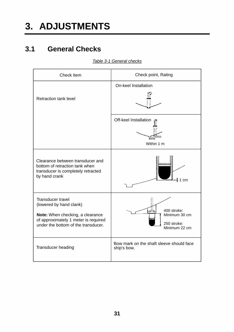
3.1 General Checks Table 3-1 General checks
On-keel Installation
Off-keel Installation
Within 1 m
1 cm
400 stroke: Minimum 30 cm
250 stroke:Minimum 22 cm
Check Item Check point, Rating
Retraction tank level
Clearance between transducer and bottom of retraction tank when transducer is completely retracted by hand crank
Transducer travel (lowered by hand clank)
Note: When checking, a clearance of approximately 1 meter is required under the bottom of the transducer.
Transducer headingBow mark on the shaft sleeve should face ship's bow.

32
Table 3-1 general checks (con’t)
Check Item Check point, Rating
Wiring check • All cables are correctly connected.
• All lead wires are tightly fixed with contact pins or crimp-on lugs.
• All screws are firmly fastened.
• Cables are firmly secured.
• Cables shields are properly grounded. Rejecting source of noise and interference
• Noise generating machinery (motor, radiotelephone, TV set, etc.) are not placed nearby.
• Magnetic devices are not placed in the vicinity of display unit.
Earth • Each unit is grounded with a copper strap. Ship’s mains voltage • Ship’s mains voltage is stable 12, 24 or 32
VDC. Watertightness • Water should not leak from the main body
flange or along the main shaft.
3.2 TX Frequency Checking Check the TX frequency after the installation.
1. Press the [MENU] key to open the user menu.
2. Press the cursor pad to select SYS at the top of the menu display.
NOYES
: SELECT : CHANGE MENU: END
MENU COM1 COM2 HORZ VERT ES SHORT-CUT SYS
GO TO SYS MENU
User menu (SYS)
3. Press the [ ] to select GO TO SYS MENU.
4. Press the [ ] to select YES to display the system menu.

33
RANGE-SONAR MODE
RANGE-VERTICAL MODE
RANGE-E/S MODE
ADJ MOTION SENSOR
TX FREQ ADJUST
TEST
TEST PATTERN
DEMO MODE
DEFAULT
: SELECT : MENU DISPLAY MENU: END
SYSTEM SETTING:
COLOR PALETTE
LANGUAGE
SYSTEM BACKUP
LOAD BACKUP DATA
HEADING OFFSET, DRAFT OFFSET
** SYSTEM MENU **
RANGE-TRACK MODE
System menu
5. Press the [ ] to select TEST.
6. Press the [ ] to show the test display.
MAIN PROGRAM NO. 0650110-**.**
RAM : OK
ROM : OK
VRAM : OK
PANEL CPU : OK
NMEA : OK
PANEL PROGRAM NO. 0650104-0**
TX FREQUENCY : 180 kHz
ROLL : 10
PITCH : 10
PULSES NG
TEST COUNT= : 0
TRAIN 359 0
REMOTE CONTROLPANEL
0 0 00 00 0 0
0 EXIT0 0
0 0
0 0
0
0
0 0 0 0
0 0 0 0
0
0
1 0 0 0 0(LED)
0 0 0
0 0 0 0
** Program Version No.
Test display
7. Check the frequency at the TX FREQUENCY line on the test display.
8. Press the [MENU] key several times to close the menu.

34
3.3 Heading Alignment/Soundome Setting
Heading alignment The heading line can be compensated through the system menu ( –30° to +30°).
1. Locate a target (buoy, etc.) in the bow direction and display it on the screen at close range, read deviation. The heading alignment is correct when the target is displayed at 12 o’clock on the screen.
Heading
Buoy 12 o'clock position
When on-screen target is skewed right, transducer heading is skewed left.
Checking heading alignment
2. Press the [MENU] key to display the user menu.
3. Press the cursor pad to select SYS at the top of menu display.
NOYES
: SELECT : CHANGE MENU: END
MENU COM1 COM2 HORZ VERT ES SHORT-CUT SYS
GO TO SYS MENU
User menu (SYS)
4. Press the [ ] to select GO TO SYS.
5. Press the [ ] to select YES to display the system menu.

35
RANGE-SONAR MODE
RANGE-VERTICAL MODE
RANGE-E/S MODE
ADJ MOTION SENSOR
TX FREQ ADJUST
TEST
TEST PATTERN
DEMO MODE
DEFAULT
: SELECT : MENU DISPLAY MENU: END
SYSTEM SETTING:
COLOR PALETTE
LANGUAGE
SYSTEM BACKUP
LOAD BACKUP DATA
HEADING OFFSET, DRAFT OFFSET
** SYSTEM MENU **
RANGE-TRACK MODE
System menu
6. Press the [ ] to select HEADING OFFSET, DRAFT OFFSET, and then press the [ ] to display the heading offset display.
0 ˚ (-180˚ - +180˚)HEADING :
: CHANGE MENU: END
** HEADING OFFSET/DRAFT OFFSET **
0.0 ˚ (0.0 - 60.0m)DRAFT :
: SELECT
Head offset display
7. Press the [ ] [ ] to align heading (1 step) so that the target on heading direction appears at the twelve o’clock position.
8. Press the [ ] to choose draft.
9. Press the [ ] [ ] to set ship’s draft.
10. Press the [MENU] key several times to close the menu.
11. Confirm that the target on heading direction appears at the twelve o’clock position.
Soundome setting Confirmation Set the serial number for the soundome connected, under nine-999 or over 1000.
1. Open the SYSTEM MENU following step 1 to 4 in the above.
2. Select SYSTEM SETTING, and then press the [ ] to open the SYSTEM SETTING 1 menu.

36
OFF 10sec 30sec 1min 3min 6min
OFF FLOW FROM FLOW TO
L/L LOPPOSITION :
CURRENT DATA :
HEADING INDICATION : TRUE AZ
TEMP : C F
CUSTOM KEY : PRESET KEY SHORT-CUT KEY
TARGET L/L : OFF ON
EMPHASIS MODE : OFF NORMAL RED
ETA MARK :
: SELECT : CHANGE MENU: END
MENU 1 2
m ft fa HIRO P/B
NORTH MARK : OFF ON
CSE DATA : NAV GYRO
NAV DATA : GPS LoranC LoranA DR DECCA OTHERS
TVG CORRECTION : OFF 1/2 1/1
UNIT :
** SYSTEM SETTING 1 **
TRACK : OFF ON
System setting 1 menu
3. Press the cursor pad to select 2 and press the [ ] to show SYSTEM SETTING 2 menu.
OFF ON
OFF (OFF, 5-15 kt)AUTO RETRACTION :
SPEED ALARM/MESSAGE :
DEFAULT SETTING : NO YES
: SELECT : CHANGE MENU: END
MENU : 1 2
** SYSTEM SETTING 2 **
SOUNDOME SER. NO. : ~999 1000~
MAXIMUM ALLOWABLE SPEED IS 15 KNOTS WHILE SOUNDOME IS BEINGRETRACTED. IF VESSEL HAS REPAID ACCELERATION CAPABILITIES,AUTO RETRACTION SETTINGS OF 10-12 KNOTS ARE MANDATORY TOAVOID CATASTROPHIC DAMAGE TO SOUNDOME ASSY. ANY PHISICALDAMAGE TO THE SOUDOME ASSY. IS CONSIDERED ABUSE ANDIS NOT A WARRANTY ISSUE.
SWEEP INDICATOR : DOT LINE
OFF ONSTABILIZER :
System setting 2 menu
4. Confirm the soundome serial number at SOUNDOME SER. NO. If change, press [ ] to select SOUNDOME SER. NO. and then press the [ ] to select ~999 or 1000~ appropriately.
5. Press the [MENU] key several times to close the menu.

37
3.4 Adjustment of Motion Sensor When the ship has a semi-permanent inclination, offset it as follows.
1. Press the [MENU] key to display the user menu.
2. Press the cursor pad to select SYS at the top of the menu display.
NOYES
: SELECT : CHANGE MENU: END
MENU COM1 COM2 HORZ VERT ES SHORT-CUT SYS
GO TO SYS MENU
Display to select the system menu
3. Press the [ ] to select GO TO SYS.
4. Press the [ ] to select YES.
RANGE-SONAR MODE
RANGE-VERTICAL MODE
RANGE-E/S MODE
ADJ MOTION SENSOR
TX FREQ ADJUST
TEST
TEST PATTERN
DEMO MODE
DEFAULT
: SELECT : MENU DISPLAY MENU: END
SYSTEM SETTING:
COLOR PALETTE
LANGUAGE
SYSTEM BACKUP
LOAD BACKUP DATA
HEADING OFFSET, DRAFT OFFSET
** SYSTEM MENU **
RANGE-TRACK MODE
System menu
5. Press the [ ] to select ADJ MOTION SENSOR, and then press the [ ] to display ADJ MOTION SENSOR menu.
PITCH ANGLE: 0˚ ADJ: +5 ˚ (-10˚ - +10˚)
ROLL ANGLE: 0˚ ADJ: +5 ˚ (-10˚ - +10˚)
** ADJ MOTION SENSOR **
: SELECT : CHANGE MENU: END
Adj motion sensor menu

38
6. Press [ ] [ ] to select ROLL ANGLE or PITCH ANGLE.
7. Press [ ] [ ] to adjust (-10° to +10°). By using a clinometer or other means, measure ship’s semi-permanent inclination angle. Take
the polarity of the angle as follows. For example, if the stern is 3° down, set -3°.
0 + –
0 + –
+ - ROLL ANGLE Starboard up Starboard down PITCH ANGLE Stern up Stern down
8. Press the [MENU] key several times to close the menu.
3.5 System Back Up After setting the equipment follow the procedure below to back up system settings. Backup data can be loaded in the event of equipment trouble, to restore previous system settings.
1. Press the [MENU] key to display the user menu.
2. Press the cursor pad to select SYS at the top of the menu.
NOYES
: SELECT : CHANGE MENU: END
MENU COM1 COM2 HORZ VERT ES SHORT-CUT SYS
GO TO SYS MENU
Display to select the system menu
3. Press [ ] to select GO TO SYS MENU.
4. Press [ ] to select YES. The system menu appears.

39
RANGE-SONAR MODE
RANGE-VERTICAL MODE
RANGE-E/S MODE
ADJ MOTION SENSOR
TX FREQ ADJUST
TEST
TEST PATTERN
DEMO MODE
DEFAULT
: SELECT : MENU DISPLAY MENU: END
SYSTEM SETTING:
COLOR PALETTE
LANGUAGE
SYSTEM BACKUP
LOAD BACKUP DATA
HEADING OFFSET, DRAFT OFFSET
** SYSTEM MENU **
RANGE-TRACK MODE
System menu
5. Press [ ] to select SYSTEM BACKUP.
6. Press [ ] to display the system backup menu.
NO YESARE YOU SURE? :
: CHANGE MENU: END
** SYSTEM BACK UP**
NOTE: OVERWITES PREVIOUS BACKUP DATA
System backup menu
7. Press [ ] to select YES.
8. Press the [MENU] key. The backup data is loaded, and then return to the system menu.
9. Press the [MENU] key to return to the normal display.

40
3.6 Setting of Interface Unit Set DIP switch S1 in the interface unit as follows.
• The monitor unit MU-100C or the interface unit is connected to DATA/VIDEO OUT port of the interface unit : all OFF.
• Nothing is connected to DATA/VIDEO OUT port of the interface unit : all ON.
S1
ON
J6*J7*
BU
FF
ER
TH
RO
UG
H
J1 J3J2
*: J6 and J7 set to "THROUGH" side.
Interface unit, DIP switch S1 location
ProcessorUnit
ExternalMonitor
InterfaceUnit
S1:All ONS1:All OFF
ProcessorUnit
ExternalMonitor
MonitorUnit
Interface Unit
S1:All OFF
ProcessorUnit
ExternalMonitor
InterfaceUnit
S1:All ON
ExternalMonitor
InterfaceUnit

41
Input/Output Description The CH-250 can receive/transmit the following sentences in NMEA 0183 format.
Input
• GLL: GPS position
• VTG: Ground speed/true course
• DBT: Depth (Ignore talker, NMEA Ver1.5)
• DBS: Depth (Ignore talker)
• DPT: Depth (Ignore talker, NMEA Ver2.0)
• GGA: GPS position/Speed/Course (Ignore talker)
• VDR: Current direction/current speed (Ignore talker)
• RMA: Loran C position/LOP/Speed/Course
• RMC: GPS position/Speed/Course
• VHW: Water speed/Heading
• HDG: Heading
• MTW: Temperature
• HDM: Heading
• HDA: Temperature (Ignore talker)
• HDT: Heading
Output
• TLL: When entering event mark.
Priority (Input) Own ship�s position GGA>RMC>RMA>GLL LOP can be displayed only when RMA is inputted.Course RMC>RMA>VTG Heading HDG>VHW>HDM Speed RMC>RMA>VTG>VHW Depth DPT>DBT>DBS Temperature MTW>MDA Current VDR

This page is intentionally left blank.
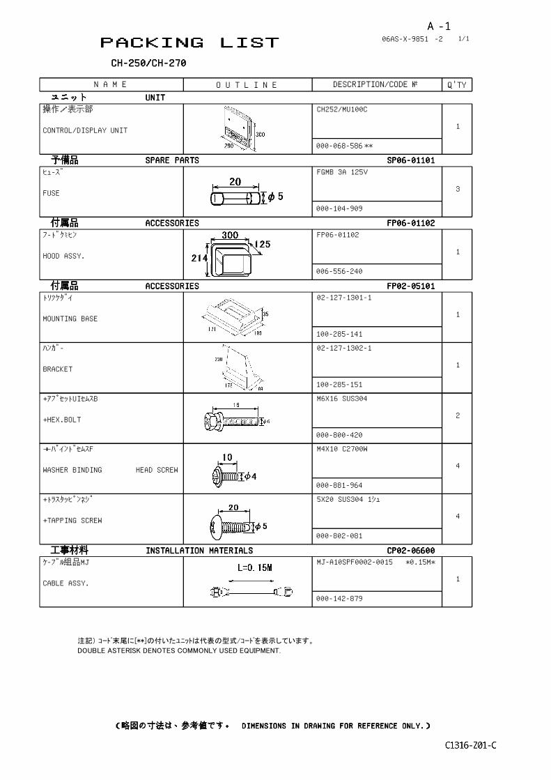
PACKING LISTPACKING LISTPACKING LISTPACKING LIST 06AS-X-9851 -2
CH-250/CH-270CH-250/CH-270CH-250/CH-270CH-250/CH-270
N A M E O U T L I N E DESCRIPTION/CODE № Q'TY
1/1
ユニットユニットユニットユニット UNITUNITUNITUNIT操作/表示部
CONTROL/DISPLAY UNIT
CH252/MU100C
000-068-586
1
**
予備品予備品予備品予備品 SPARE PARTSSPARE PARTSSPARE PARTSSPARE PARTS SP06-01101SP06-01101SP06-01101SP06-01101ヒューズ
FUSE
FGMB 3A 125V
000-104-909
3
付属品付属品付属品付属品 ACCESSORIESACCESSORIESACCESSORIESACCESSORIES FP06-01102FP06-01102FP06-01102FP06-01102フードクミヒン
HOOD ASSY.
FP06-01102
006-556-240
1
付属品付属品付属品付属品 ACCESSORIESACCESSORIESACCESSORIESACCESSORIES FP02-05101FP02-05101FP02-05101FP02-05101トリツケダイ
MOUNTING BASE
02-127-1301-1
100-285-141
1
ハンガー
BRACKET
02-127-1302-1
100-285-151
1
+アプセットUIセムスB
+HEX.BOLT
M6X16 SUS304
000-800-420
2
+バインドセムスF
WASHER BINDING HEAD SCREW
M4X10 C2700W
000-881-964
4
+トラスタッピンネジ
+TAPPING SCREW
5X20 SUS304 1シュ
000-802-081
4
工事材料工事材料工事材料工事材料 INSTALLATION MATERIALSINSTALLATION MATERIALSINSTALLATION MATERIALSINSTALLATION MATERIALS CP02-06600CP02-06600CP02-06600CP02-06600ケーブル組品MJ
CABLE ASSY.
MJ-A10SPF0002-0015 *0.15M*
000-142-879
1
注記) コード末尾に[**]の付いたユニットは代表の型式/コードを表示しています。
DOUBLE ASTERISK DENOTES COMMONLY USED EQUIPMENT.
(略図の寸法は、参考値です。 DIMENSIONS IN DRAWING FOR REFERENCE ONLY.)(略図の寸法は、参考値です。 DIMENSIONS IN DRAWING FOR REFERENCE ONLY.)(略図の寸法は、参考値です。 DIMENSIONS IN DRAWING FOR REFERENCE ONLY.)(略図の寸法は、参考値です。 DIMENSIONS IN DRAWING FOR REFERENCE ONLY.)
YAMASAKI
YAMASAKI
C1316-Z01-C
KIMURA
A - 1

PACKING LISTPACKING LISTPACKING LISTPACKING LIST 06AS-X-9852 -1
CH-250/CH-270CH-250/CH-270CH-250/CH-270CH-250/CH-270
N A M E O U T L I N E DESCRIPTION/CODE № Q'TY
1/1
ユニットユニットユニットユニット UNITUNITUNITUNIT操作部
CONTROL UNIT
CH-252
000-068-484
1
**
付属品付属品付属品付属品 ACCESSORIESACCESSORIESACCESSORIESACCESSORIES FP06-01120FP06-01120FP06-01120FP06-01120操作取付台
CONTROL UNIT MOUNTING PLATE
06-021-2111-0
100-279-740
1
ソウサブラケット
BRACKET
06-021-2112-0
100-281-880
1
+トラスタッピンネジ
+TAPPING SCREW
5X20 SUS304 1シュ
000-802-081
2
ホールプラグ
HOLE PLUG
DP-687 クロ
000-808-417
2
六角セムスB スリワリ
HEX.BOLT (SLOTTED,WASHER HEAD)
M4X12 SUS304
000-882-040
4
工事材料工事材料工事材料工事材料 INSTALLATION MATERIALSINSTALLATION MATERIALSINSTALLATION MATERIALSINSTALLATION MATERIALS CP02-06610CP02-06610CP02-06610CP02-06610ケーブル組品MJ
CABLE ASSY.
MJ-A10SPF0002-015
000-142-878
1
(*)
工事材料工事材料工事材料工事材料 INSTALLATION MATERIALSINSTALLATION MATERIALSINSTALLATION MATERIALSINSTALLATION MATERIALS CP02-06620CP02-06620CP02-06620CP02-06620ケーブル組品MJ
CABLE ASSY.
MJ-A10SPF0002-050
000-131-411
1
(*)
注記) 1.(*)印の信号ケ-ブル組品は、選択できます。
CABLE IS SELECTIVE ON DEMAND.
2.コード末尾に[**]の付いたユニットは代表の型式/コードを表示しています。
DOUBLE ASTERISK DENOTES COMMONLY USED EQUIPMENT.
(略図の寸法は、参考値です。 DIMENSIONS IN DRAWING FOR REFERENCE ONLY.)(略図の寸法は、参考値です。 DIMENSIONS IN DRAWING FOR REFERENCE ONLY.)(略図の寸法は、参考値です。 DIMENSIONS IN DRAWING FOR REFERENCE ONLY.)(略図の寸法は、参考値です。 DIMENSIONS IN DRAWING FOR REFERENCE ONLY.)
YAMASAKI
C1316-Z02-B
KIMURA
A - 2


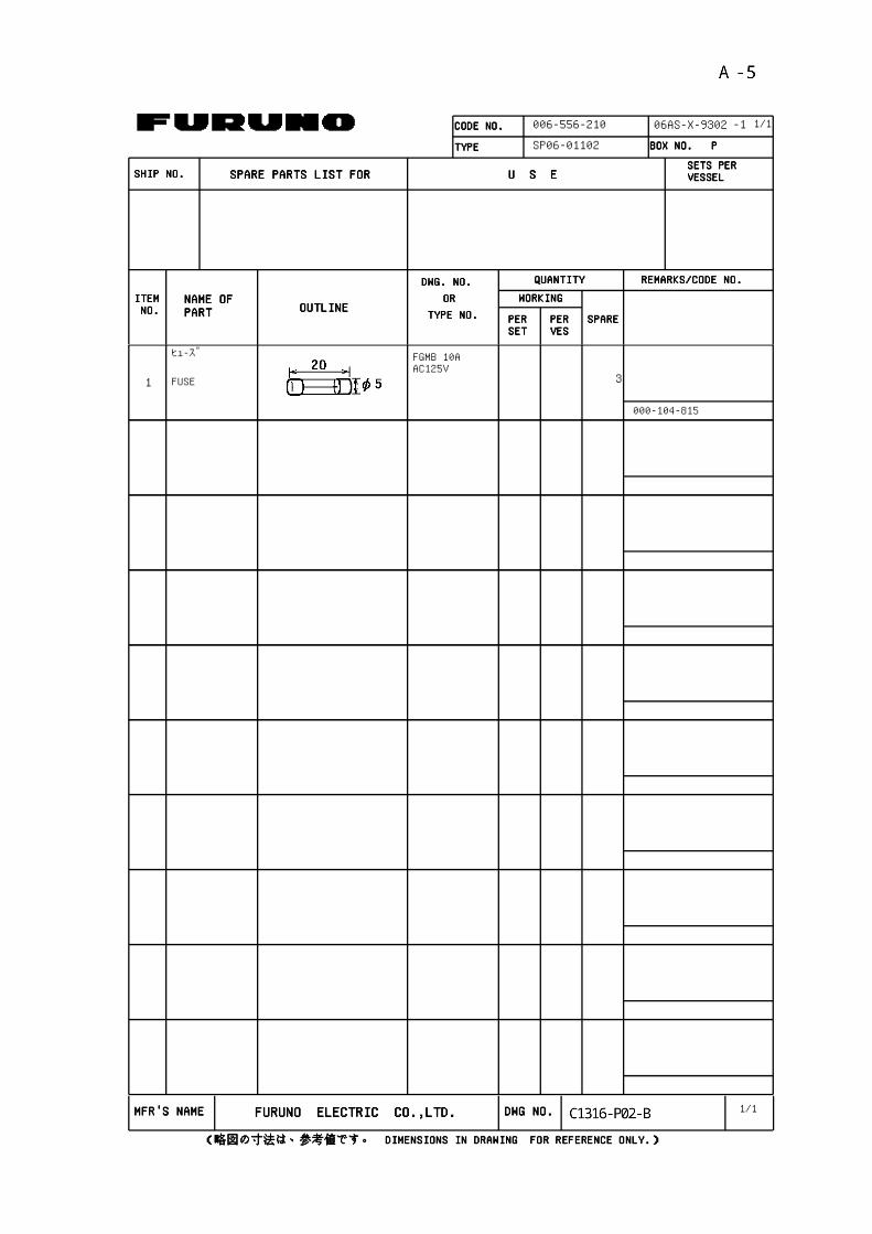
CODE NO.CODE NO.CODE NO.CODE NO. 006-556-210
TYPETYPETYPETYPE SP06-01102
ITEMITEMITEMITEM NO. NO. NO. NO.
NAME OF NAME OF NAME OF NAME OF PARTPARTPARTPART OUTLINEOUTLINEOUTLINEOUTLINE
DWG. NO. DWG. NO. DWG. NO. DWG. NO. OR OR OR OR
PERPERPERPERSETSETSETSET
PERPERPERPERVESVESVESVES
SPARESPARESPARESPARE
WORKINGWORKINGWORKINGWORKING
QUANTITYQUANTITYQUANTITYQUANTITY REMARKS/CODE NO.REMARKS/CODE NO.REMARKS/CODE NO.REMARKS/CODE NO.
BOX NO. P BOX NO. P BOX NO. P BOX NO. P
SHIP NO.SHIP NO.SHIP NO.SHIP NO. SPARE PARTS LIST FOR SPARE PARTS LIST FOR SPARE PARTS LIST FOR SPARE PARTS LIST FOR U S EU S EU S EU S ESETS PER SETS PER SETS PER SETS PER VESSELVESSELVESSELVESSEL
-1
TYPE NO.TYPE NO.TYPE NO.TYPE NO.
06AS-X-9302 1/1
ヒュ-ズ FGMB 10A AC125V
3FUSE
000-104-815
1
1/1MFR'S NAMEMFR'S NAMEMFR'S NAMEMFR'S NAME FURUNO ELECTRIC CO.,LTD.FURUNO ELECTRIC CO.,LTD.FURUNO ELECTRIC CO.,LTD.FURUNO ELECTRIC CO.,LTD. DWG NO.DWG NO.DWG NO.DWG NO.
(略図の寸法は、参考値です。 DIMENSIONS IN DRAWING FOR REFERENCE ONLY.)(略図の寸法は、参考値です。 DIMENSIONS IN DRAWING FOR REFERENCE ONLY.)(略図の寸法は、参考値です。 DIMENSIONS IN DRAWING FOR REFERENCE ONLY.)(略図の寸法は、参考値です。 DIMENSIONS IN DRAWING FOR REFERENCE ONLY.)
YAMASAKI
C1316-P02-B
KIMURA
A - 5

CODE NO.CODE NO.CODE NO.CODE NO. 006-556-220
TYPETYPETYPETYPE SP06-01111
ITEMITEMITEMITEM NO. NO. NO. NO.
NAME OF NAME OF NAME OF NAME OF PARTPARTPARTPART OUTLINEOUTLINEOUTLINEOUTLINE
DWG. NO. DWG. NO. DWG. NO. DWG. NO. OR OR OR OR
PERPERPERPERSETSETSETSET
PERPERPERPERVESVESVESVES
SPARESPARESPARESPARE
WORKINGWORKINGWORKINGWORKING
QUANTITYQUANTITYQUANTITYQUANTITY REMARKS/CODE NO.REMARKS/CODE NO.REMARKS/CODE NO.REMARKS/CODE NO.
BOX NO. P BOX NO. P BOX NO. P BOX NO. P
SHIP NO.SHIP NO.SHIP NO.SHIP NO. SPARE PARTS LIST FOR SPARE PARTS LIST FOR SPARE PARTS LIST FOR SPARE PARTS LIST FOR U S EU S EU S EU S ESETS PER SETS PER SETS PER SETS PER VESSELVESSELVESSELVESSEL
-3
TYPE NO.TYPE NO.TYPE NO.TYPE NO.
06AS-X-9303 1/1
ヒューズ FGMB 0.2A 125V
3FUSE
000-121-723
1
1/1MFR'S NAMEMFR'S NAMEMFR'S NAMEMFR'S NAME FURUNO ELECTRIC CO.,LTD.FURUNO ELECTRIC CO.,LTD.FURUNO ELECTRIC CO.,LTD.FURUNO ELECTRIC CO.,LTD. DWG NO.DWG NO.DWG NO.DWG NO.
(略図の寸法は、参考値です。 DIMENSIONS IN DRAWING FOR REFERENCE ONLY.)(略図の寸法は、参考値です。 DIMENSIONS IN DRAWING FOR REFERENCE ONLY.)(略図の寸法は、参考値です。 DIMENSIONS IN DRAWING FOR REFERENCE ONLY.)(略図の寸法は、参考値です。 DIMENSIONS IN DRAWING FOR REFERENCE ONLY.)
YAMASAKI
C1316-P03-C
KIMURA
A - 6


三好 悦子
D-2


takahasi
takahasi
三好 悦子
D-8 D-8