Installation Manual - Ricohrfg-esource.ricoh-usa.com/stellent/groups/public/documents/service... ·...
102
Installation Manual UC5e (Revision 2-1)
-
Upload
nguyentuong -
Category
Documents
-
view
218 -
download
3
Transcript of Installation Manual - Ricohrfg-esource.ricoh-usa.com/stellent/groups/public/documents/service... ·...

Installation Manual
UC5e (Revision 2-1)

2 UC5e IM Rev 2-1 July 2004

3UC5e IM Rev 2-1 July 2004
ZipRip hardware and software is the property of SMA (Pty) Ltd. AustraliaP.O. Box 774, Fyshwick 2609, ACT Australia
This documentation or any part of it may not be reproduced, stored or trans-mitted in any form, including but not limited to electronic, photocopying,mechanical copying, electrostatic copying, recording or other means withoutexpress written permission of SMA (Pty) Ltd. Australia
Windows is a registered trademark of Microsoft Corporation. Macintosh is aregistered trademark of Apple Computers Incorporated. Other brand or prod-uct names, throughout this document, are trademarks or registered trade-marks of their respective holders.
Ricoh and PriPort are registered trademarks of Ricoh Japan.

4 UC5e IM Rev 2-1 July 2004
Table of ContentsIntroduction......................................................................... 5
Safety Information ............................................................. 6
Basic Specification ............................................................. 7
Digital Duplicator Driver Groups .................................... 8
Package Contents ............................................................. 10
Video Interface Installation Preparation........................ 12 Model C238 amd C247 .................................................... 13 Model C239, C244 and C249 ........................................... 14 Model C252 ...................................................................... 15ZipRIP Installation Guide for model C237 and C248 .. 16
ZipRIP Installation Guide for model C235 .................... 25
ZipRIP Installation Guide for model C238 and C247 .. 34
ZipRIP Installation Guide for model C239 and C244 .. 41
ZipRIP Installation Guide for model C252 .................... 49
ZipRIP Installation Guide for model C249 .................... 54
Testing your UC5E ............................................................ 61
Activity Indicator ............................................................... 62
Troubleshooting GDI ........................................................ 63

5UC5e IM Rev 2-1 July 2004
IntroductionThe UC5E is a high speed interface for Digital Duplicators. With a UC5Eyou can print directly from your PC to your Digital Duplicator. This willsignificantly improve the quality of your printed material as well as speedup your printing jobs.
The UC5E’s modular design makes it easy to upgrade to PostScript or addnetwork support as your printing requirements become more demanding.
We are confident that you will find it a pleasure to use and an asset to yourorganisation.
Plug into interface port
Plug into „centronics“parallel printer port
Windows 3.11, Windows 95/98/ME, Windows NTand Windows 2000 based PC.

6 UC5e IM Rev 2-1 July 2004
Safety InformationThis equipment must be connected to SELV circuits and other equipmentcomplying with the requirements of SELV circuits as defined in the stand-ards EN60950, IEC950 and CSAC22.2 No. 950, UL 1950.
Sicherheit-AuskünfteDieseAusrüstung muß zur SELV Schaltungen von anderenAusrüstungen,diemitden Forderungen von SELV Schaltungendie in den StandardsEN60950, IEC950 und CSAC22.2 N0 950, UL1950 definiert werden,nach kommen.
Renseignements de sécuritéILest absolunent nécessaired’interconnecter cet équipment dux circuitsSELVde touté quipment qui se conforme dux besoirs des circuits SELV commeprécisés dux standards EN60950, IEC950 et CSAC22.2 NO. 950, UL 1950

7UC5e IM Rev 2-1 July 2004
Basic SpecificationsPrinter Language: ................................Windows GDI,
Supported Resolutions: .....................300, 400 and 600 dpi.
Graphics Screening: ..........................Coarse, Fine, Line Art, Error Diffu-sion. Density control supported.
Supported Drivers: ..............................Win 95/98/ME., Win 2000, Win NTand Win XP.
Ports: ..................................................ECP/EPP parallel port.
On Board Memory: ...........................16. MB
SupportedDigital Duplicator Brands: ................Ricoh, Gestetner, Rex Rotary,
Nashuatec, Savin, and Standard. NBcheck that your model has interfacesupport.
Certification ......................................CE, UL, FCC, Class A.
Supply Voltage ...................................5 Volts from Digital Duplicator

8 UC5e IM Rev 2-1 July 2004
Driver Name Model Digital Duplicator ModelZipRIP Classic A C224 VT2200/5327/1252/CP327/3200DNP
C226 VT2250/5329L/2546/CP329L/325DNPC222 VT2400/5360/1270/CP360
ZipRIP Classic B C210 VT3500/5375/1280/CP375C218 VT3600/5380/1285/CP380C223 VT3800/5385/1290/CP385/330DNP
ZipRIP Classic X C228 VT6000/5390/1295/CP390/3400DNP/SD600ZipRIP Pro A C231 JP1010/5306/1224/CP306
C237 JP1210/5308/1225/CP308C248 JP1215/5308+/1225+/CP308+
ZipRIP Pro B C231 JP1030/5306L/1224L/CP306/3150DNP/D300C231 JP1050/5306B/1224B/CP306BC237 JP1230/5308L/3150eDNP/SD330C237 JP1250/5308B/1225B/CP308BC247 JP2800/5425C (China)C248 JP1255/5308b+/1225B+/CP380C248 JP1235/5309L/3160DNP/LDD020/SD333550C248 JP1250/5300 (China)C252 JP750/6123CPC252 JP780C/5410C (China)C252 JP730/6123LCP/LDD730
ZipRIP Pro C C229 JP5000/5450/1560/CP450/3350DNP/SD400C239 JP5500/5450/5455/1560/CP450/3360DNP/
SD450C249 JP4500/CP6244/3560DNP/SD420/LDD145
*Models with suffix PT indicate additional paper tray unit installed
Digital Duplicator Driver Groups

9UC5e IM Rev 2-1 July 2004
*Models with suffix PT indicate additional paper tray unit installed
Driver Name Model Digital Duplicator ModelZipRIP Pro C PT C232 JP5800/5480/1580/CP480
C239 JP5500/5450/5455/1560/CP450/3360DNP/SD450
ZipRIP Pro E C238 JP3000/5430/1330/CP430/3260DNP/SD370JP3800/5428C (China)
ZipRIP Pro X C235 JP8000/5490/1395/CP490/3450DNP/SD630C244 JP8500/5490+/5499/1395+/CP490+/
3460DNP/SD650ZipRIP Pro X PT C235 JP8000/5490/1395/CP490/3450DNP/SD630
C244 JP8500/5490+/5499/1395+/CP490+/3460DNP/SD650
Digital Duplicator Driver Groups (Continued)

10 UC5e IM Rev 2-1 July 2004
Package ContentsCheck that you have received the following Items in your UC5E package.Components For GDI UC5E.
1. Main Board2. Mounting Plate3. Mounting Plate Cover4. 2-pin cable and connector - C2355. 2-pin cable and connector - C2376. Keypad PCB
7. 26-pin MPU Ribbon cable (C235, C237and C238)
8. 26-pin to 25-pin Ribbon PCB to Cover9. 8-pin Ribbon cable - The long cable is
for C237 the other is for C235 and C238.10. 11 x M3 x 6mm Screws11. 3 x M4 x 10mm Standoffs (C249)
1 2 3
4 5 6
7 8 9
10 11

11UC5e IM Rev 2-1 July 2004
12. 3 x M3 x 35mm Standoff13. 3 x M4 x 45mm Standoff14. 1 x M4 x 26mm Standoff15. 4 x M3 x 25mm FF Standoff16. 6 x M3 x 10mm MF Standoff17. 1 x M3 x 10mm FF Standoff18. Marguard LED and Button
19. PC DB25 Male to DB25 Male parallelCable
20. Installation CD and manuals21. 6 x Cable Ties22. 2 x 2.6mm Standoff-post - suppled with IF Kit.23. 3 x M4 x 6mm Screws
12 14
15 16 17
18 19 20
21
13
22 23

12 UC5e IM Rev 2-1 July 2004
Video Interface Installation PreparationNOTE: Video I/F Kit Type- 600, Type- 10, Type- 15, and Type- 85 are
Digital DUplicator parts, please obtain from supplier.
Before you begin the installation, you should:a. Check to make sure that you have all of the items needed to
complete successful installation.b. Read the documentation to familiarize yourself with the in-
stallation procedures.c. Have the following additional items available:
- Service manual relevant machine- User's Guide- A container to hold screws and other removed components- Tool Kit
For the C237, C238 and C252 model installation, you should use Video Inter-face kit Type-10 or Type 15, provided by the original manufacturer.For: Europe, Far East and Asia use Type-10 Interface kit.For: USA and Latin America use Type-15 Interface kit.Installation procedure for both Interface kits follow.Video I/F Kit Type-10 and Type- 15 Parts List
No. Description Qty.
32 Interface Board 1
33 Relay Harness 1
34 Stepped Screw - M2 x ,6 2
35 Tapping Screw - M3 x 6 2
NOTE:Item number 33 is not used for the model C237, C238 and C252 installation.

13UC5e IM Rev 2-1 July 2004
Model C238 and C247Refer to Driver Groups List on page 8.
1. Remove the rear covers [A] [B] (8 screws).2. Remove the I/F connector cover [C] (2 screws).3. Install the I/F board [D] (accessories) in CN117 [E] on the MPU (2 screws).4. Attach the cable [F] (accessories) to the connector bracket (2 screws) and
clamp the cable (6 clamps).5. Connect the connector [G] at the opposite end to the I/F board.6. Re-install the rear covers.

14 UC5e IM Rev 2-1 July 2004
Model C239, C244 and C249Refer to Driver Groups List on page 8
1. Remove the rear cover [A].
2. Cut away the blindfold cover [B] on the right rear cover.3. Install the Video I/F board [C] to the MPU. (2 screws)4. Connect the cable [D] to the Video I/F board. (2 screws, 2 spacers)
NOTE: You need to adjust the length of the harness using the bind [E]enclosed.
5. Reinstall the rear cover.

15UC5e IM Rev 2-1 July 2004
Model C252Refer to Driver Groups List on page 8Accessory CheckCheck the quantity and condition of the accessories in the box against thefollowing list:
Description Qty1. Interface Board ................................................................... 12. Interface Cable.................................................................... 13. Screw M3 x 6 ..................................................................... 24. Lock Screw ......................................................................... 25. Washer ................................................................................ 2
Installation Procedure
1. Remove the rear cover [A]. ( Screws x 5)2. Remove the I/F connector cover [B]. (Screws x1)
3. Connect the I/F board [C] (accessories) to CN108 [D] on the MPU.(Screws x 2)
4. Attach the cable [E] (accessories) to the connector bracket. (Screws x 2)
5. Connect the connector [F] at the opposite end to the I/F board.
6. Re-install the rear cover.
[A]
[B] [C]
[D]
[E]
[F]
16 UC5e IM Rev 2-1 July 2004
ZipRIP Installation Guide for model C237 and C248Tools required:-
a. Phillips screw driverb. Flat head screw driverc. Antistatic equipment
Discard the following parts for this installation:-
a. Part No. VU5E 05 301b. Part No. VU5E 05 404c. Part No. VU5E 05 402d. Part No. VU5E 10 002
Installation Time:-
This installation should take 30 minutes excluding the time taken toinstall the video board.
1. Turn off the main switch and unplug the power cord.2. Remove your UC5E and ancillary items from the box.3. Open the scanner unit.4. Remove the upper rear cover.5. Remove the rear cover.6. Remove the MPU cover.

17UC5e IM Rev 2-1 July 2004
7. Remove screw [A],{B] and [C]. Keep them aside for later use.8. Locate the three standoffs supplied. Mount them into the holes as fol-
lows:Into hole marked [A] in Figure 2a screw in the 45 mm standoff [D].Into hole marked [B] in Figure 2a screw in the 45 mm standoff [D].Into hole marked [C] in Figure 2a screw in the 26mm standoff [E].NOTE:1) Tighten these standoffs with a flat screwdriver.2) The bracket [F] becomes free without screw [B] Hold bracket
[F] by the hand until you screw in standoff [D].
Figure 2a
[A]
[B]
[C][D]
[E]
[F]

18 UC5e IM Rev 2-1 July 2004
9. Locate the mounting plate [A], part no. VU5E 05 406. Orientate theplate correctly, as shown.
10. Attach five "M3 x 6 mm screws" on the mounting plate [A], then attachfour "M3 x 10mm male to female standoffs" and one M3 x 10mm fe-male to female standoff" [B].NOTE:There are three different size holes on the mounting plate [A]. Use 5 ofthe 6 small tapped holes, and the other holes are not used.(See Figure 2b)
Figure 2b
[A] [B]
�

19UC5e IM Rev 2-1 July 2004
11. Place the assembled mounting plate [A] onto the standoffs on the chassisand secure using the three M4 screws [B] set aside in step 7.
12. Locate the UC5E main board [C], Part No. VU5E 05 200.CAUTION:THIS PART IS VERY SENSITIVE TO STATIC.PLEASE ENSURE THE CORRECT ANTISTATIC PRECAUTIONSARE TAKEN.The RAM SIMM [D] should be on the left.
13. Secure the main board by screwing in a M3 x 6mm screw [E] into theleft middle standoff.
14. Install four "M3 x 25mm female to female standoff" [F].
Figure 2c
[A][B]
[C]
[D] [E]
[F]
20 UC5e IM Rev 2-1 July 2004
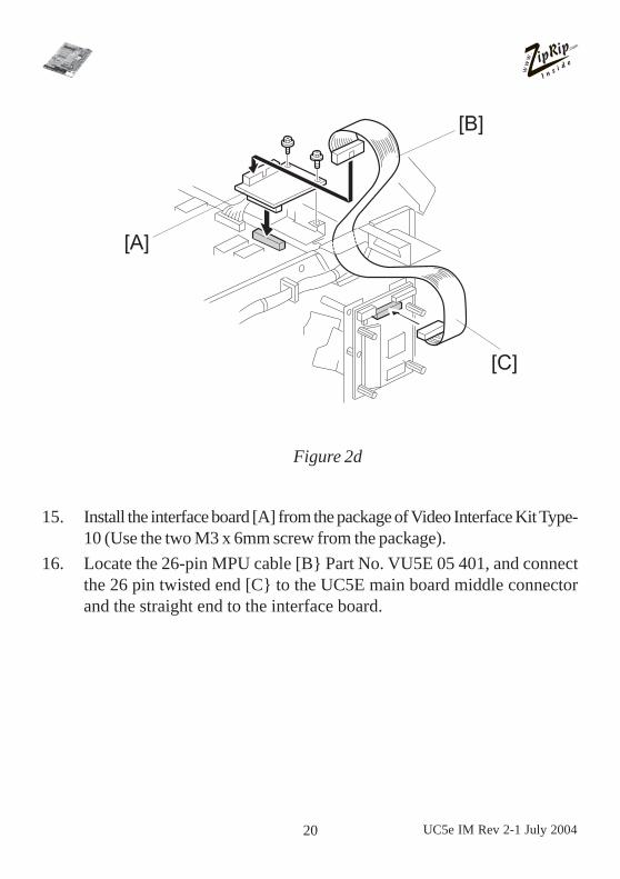
15. Install the interface board [A] from the package of Video Interface Kit Type-10 (Use the two M3 x 6mm screw from the package).
16. Locate the 26-pin MPU cable [B} Part No. VU5E 05 401, and connectthe 26 pin twisted end [C} to the UC5E main board middle connectorand the straight end to the interface board.
Figure 2d
[A]
[B]
[C]

21UC5e IM Rev 2-1 July 2004
17. Locate the cable [A] Part No. VU5 05 410, and connect the 26 pinribbon cable end to the outer connector on the UC5E main board.The DB25 end is connected to the DB 25 cut out on the chassis of themain frame using the two M3 x 5mm jack posts supplied in the IF KitType-10.
18. Reinstall the MPU Cover, the rear cover and then the upper rear coverof the Digital Duplicator.
Figure 2e
[A]

22 UC5e IM Rev 2-1 July 2004
19. Disconnect the connector on CN114.NOTE:It is not necessary to remove the cable from the machine as it becomesredundant.
20. Locate the red and black power cable [A], Part No. VU5E 05 300.Connect this cable CN114 on the MPU of the Digital Duplicator and J4connector on the UC5E main board.NOTE:Secure the RED and BLACK power cable to the loom running alongthe MPU with the 4 cables ties supplied, ensuring that the cable and theloom does not catch on the MPU cover.
Figure 2f
[A]
CN114

23UC5e IM Rev 2-1 July 2004
21. Locate the Marguard LED and button assembly [A], part number VU5E 10010. Peel the plastic of the back of the Marguard LED and button assembly[A] and stick it onto the bracket [B] of the Digital Duplicator.
22. Secure the keypad M3 x 10mm standoff [C], then mount the keypadPCB [D] onto the standoff [C] using a M3 screw.
23. Connect the marguard cable into the flat connector on the KeypadPCB [D].NOTE:1) Make sure the marguard is positioned correctly on bracket so that
it can be seen through the upper rear cover cutout.2) The button connectors have no polarity therefore they can be con
nected in either way.
Figure 2g
[B]
[C]
[A]
[D]

24 UC5e IM Rev 2-1 July 2004
24. Locate the 8 pin ribbon cable [A], part number VU5E 10 001. Connectthe white pin connector onto the keypad PCB and the 4 x 2 pin connec-tors onto the UC5E main board.NOTE:Connectors 1 & 4 are sensitive to polarity. These connectors should beplugged in with the viewable pin sides (2 x gold coloured pins) facingoutwards and the solid sides facing each other.
25. Mount the plate cover [B] onto the standoffs on the UC5E main boardand secure with four "M3 screws" supplied.
26. Plug in the power cord and switch on the Digital Duplicator.
27. The RIGHT RED LED on the membrane panel will come on and theLEFT RED LED will flash according to the version of software in theUC5E main board, e.g.: 5 flashes for version 5.
28. Press the "T" on the marguard LED and button assembly and the DigitalDuplicator will print a test page. Refer to troubleshooting section if notest page is printed.
Figure 2h[A]
[B]

25UC5e IM Rev 2-1 July 2004
ZipRIP Installation Guide for model C235Tools required:-
a. Phillips screw driverb. Flat head screw driverc. Antistatic equipment
Discard the following parts for this installation:-
a. Part No. VU5E 06 300b. Part No. VU5E 05 403c. Part No. VU5E 05 405d. Part No. VU5E 10 001e. Part No. VU5E 05 401
Installation Time:-
This installation should take 30 minutes excluding the time taken toinstall the video board.
1. Turn off the main switch and unplug the power cord.2. Remove your UC5E and ancillary items from the box.3. Remove the rear cover.
26 UC5e IM Rev 2-1 July 2004
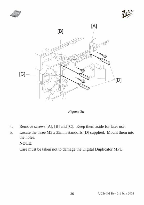
4. Remove screws [A], [B] and [C]. Keep them aside for later use.5. Locate the three M3 x 35mm standoffs [D] supplied. Mount them into
the holes.NOTE:Care must be taken not to damage the Digital Duplicator MPU.
Figure 3a
[C]
[B][A]
[D]
27UC5e IM Rev 2-1 July 2004
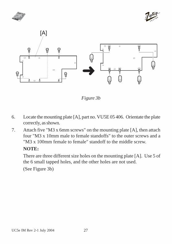
6. Locate the mounting plate [A], part no. VU5E 05 406. Orientate the platecorrectly, as shown.
7. Attach five "M3 x 6mm screws" on the mounting plate [A], then attachfour "M3 x 10mm male to female standoffs" to the outer screws and a"M3 x 100mm female to female" standoff to the middle screw.NOTE:There are three different size holes on the mounting plate [A]. Use 5 ofthe 6 small tapped holes, and the other holes are not used.(See Figure 3b)
Figure 3b
[A]
�

28 UC5e IM Rev 2-1 July 2004
8. Place the assembled mounting plate [A] onto the standoffs on the chassisand secure using the three M4 screws [B] set aside in step 4.
9. Locate a M3 x 10mm standoff and screw it through the mounting plateinto the standoff [C].
10. Locate the UC5E Main Board, Part No. VU5E 05 200, and secure it byscrewing in a M3 x 6mm screw [D].
CAUTION:THIS PART IS VERY SENSITIVE TO STATIC. PLEASE EN-SURE THE CORRECT ANTISTATIC PRECAUTIONS ARETAKEN.The RAM SIMM [E] should be on the bottom.
11. Install four "M3 x 25mm female to female standoffs" [F].
Figure 3c
[B]

29UC5e IM Rev 2-1 July 2004
12. Locate the 26-pin MPU cable, Part No. VU5E 05 402 [A}, and connectthe 26 pin twisted end to the UC5E main board middle connector andthe other straight end to the Digital Duplicator MPU.
Figure 3d
[A]

30 UC5e IM Rev 2-1 July 2004
13. Locate the 26-pin to 25-pin ribbon PCB to cover cable [A], part numberVU5E 05 410, and connect the 26 pin ribbon cable end to the outerribbon plug on the Uc5E main board. The DB25 end is connected tothe DB25 cutout on the side chassis of the Digital Duplicator using thetwo M3 x 5mm jack posts [B].NOTE:If a DB25 end cable is originally installed in the machine, remove itbefore installing the cable [A]. Re-use the two M3 x 5mm jackpostsoriginally installed in the machine.
Figure 3e
[B] [A]

31UC5e IM Rev 2-1 July 2004
14. Locate the 2 pin power cable [A], part number VU5E 05 301. Connect the4 pin side of the cable into the power plug on the UC5E main board. Con-nect the other end into connector CN702 of the Digital Duplicator.NOTE:Ensure the slack is taken up evenly on the power cable throughout it'slength from the PSU to the UC5E main board.
Figure 3f
[A]

32 UC5e IM Rev 2-1 July 2004
15. Mount the keypad PCB [A], part no. VU5E 10 005 onto the standoff onthe right and secure with a M3 x 6mm screw [B] supplied.
16. Locate the 8 pin ribbon cable [C], part number VU5E 10 002. Connectthe white pin connector end to the upright connector on the keypadPCB and the loose 4 x 2 pin connectors onto the UC5E main board.NOTE:Connectors 1& 4 are sensitive to polarity. These connectors should beplugged in with the viewable pin sides (2 x gold coloured pins) facingoutwards and the solid sides facing each other.
Figure 3g
[A]
[B]
[C]

33UC5e IM Rev 2-1 July 2004
17. Place the mounting plate cover [A] onto the standoffs on the UC5E mainboard and secure with four "M3 screws" supplied.
18. Stick the marguard LED button assembly [B] onto the outside top rightof the cover plate.NOTE:The button connectors have no polarity therefore they can be connectedin either way.
19. Plug in the power cord and switch the Digital Duplicator on.20. Press the "T" on the marguard and the Digital Duplicator will print a
test page.21. Turn the Digital Duplicator off and unplug the power cord.22. Reinstall the rear cover.23. Turn on the Digital Duplicator power switch.
Figure 3h
[A]
[B]

34 UC5e IM Rev 2-1 July 2004
ZipRIP Installation Guide for model C238 andC247Tools required:-
a. Phillips screw driverb. Flat head screw driverc. Antistatic equipment
Discard the following parts for this installation:-
a. Part No. VU5E 05 300b. Part No. VU5E 05 403c. Part No. VU5E 05 404d. Part No. VU5E 10 002e. Part No. VU5E 05 401f. Part No. VU5E 05 301
Installation Time:-
This installation should take 30 minutes excluding the time taken to install thevideo board.
NOTE When installing the UC5E on Model C238 Digital Duplicator, do not install therubber paper guides on the paper tray

35UC5e IM Rev 2-1 July 2004
1. Turn off the main switch and unplug the power cord.2. Remove the UC5E and ancillary items from the box.3. Remove the rear cover of the Digital Duplicator.4. Install the interface board [A]. (2 screws)5. Locate the cable [B], and connect the 26 pin straight end to the interface
board and twisted end [C] to main board.
[A]
[B]
[C]

36 UC5e IM Rev 2-1 July 2004
6. Mount the three 45mm standoffs [D] into the holes.
Note: Tighten these standoffs with a flat screwdriver.
7. Locate the mounting plate [E]. Orientate the plate correctly, as shown.8. Attach five M3 x 6mm screws [F] on the mounting plate, then attach four
M3 x 10mm male to female standoffs [G] and one M3 x 10mm standoff[H].
Note: There are three different size holes on the mounting plate. Use 4 of the 6small tapped holes, and other holes are not used.
[D]
[E]
[F] [G]
[H]

37UC5e IM Rev 2-1 July 2004
9. Disconnect the power cable [I].10. Place the assembled mounting plate [J] onto the standoffs on the chassis and
secure using the three M4 screws [K].11. Install the UC5E main board [L].12. Install four M3 x 25mm female to female standoffs [M].
NOTE: The RAM SIMM [N] should be on the left.
[I]
[J][K]
[L]
[M]
[N]

38 UC5e IM Rev 2-1 July 2004
13. Connect the cable [O] to the main board used in step 5.14. Connect the power cable [P] to main board.
15. Connect the 26 pin ribbon cable end to outer connector on the main board.The DB25 end is connected to the DB25 cut out on the chassis of the mainframe using the two M3 x 5mm screws.
[P]
[O]

39UC5e IM Rev 2-1 July 2004
16. Mount the keypad PCB [Q] onto the standoff on the bottom and screw withM3 x 6mm screw [R] supplied.
17. Locate the 8 pin ribbon cable [S]. Connect the white pin connector onto thekeypad PCB and the 4 x 2 pin connectors onto the main board.
NOTE: Connectors 1 and 4 are sensitive to polarity. Tlhese connectors shouldbe plugged in with the viewable pin side (2 x gold colored pins) facingoutwards and the solid sides facing each other.
[Q][R]
[S]

40 UC5e IM Rev 2-1 July 2004
18. Attach the UC5E front cover [T] and stick the marguard LED and buttonassembly [U] onto the outside bottom of the cover plate.
19. Reinstall the rear cover of the Digital Duplicator.
[T]
[U]

41UC5e IM Rev 2-1 July 2004
ZipRIP Installation Guide for Model C239 and C244Tools required:-
a. Phillips screw driverb. Flat head screw driverc. Antistatic equipment
Discard the following parts for this installation:-
a. Part No. VU5E 05 300b. Part No. VU5E 05 403c. Part No. VU5E 05 404d. Part No. VU5E 10 002e. Part No. VU5E 05 401f. Part No. VU5E 05 301
Installation Time
This installation should take 30 minutes excluding the time taken to install thevideo I/F board.

42 UC5e IM Rev 2-1 July 2004
1. Turn off the main switch and unplug the power cord.2. Remove your UC5E and ancillary items from the box.3. Remove the rear cover of the Digital Duplicator.
4. Install the video I/F board [A] from the package of Interface Cable Type85 (Use the two M3 x 6mm screws from the package).
[A]

43UC5e IM Rev 2-1 July 2004
5. Remove screws [A], [B] and [C]. Keep them aside for later use.6. Locate the three M3 x 35mm standoffs [D] supplied. Mount them into
the holes.NOTE: Care must be taken not to damage the Digital Duplicator MPU
7. Locate the mounting plate [E], part number VU5E05408. Orientate theplate correctly, as shown.
8. Attach five M3 x 6mm screws on the mounting plate [E], then attach fourM3 x 10mm male to female standoffs to the outer screws and a M3 x10mm female to female standoff to the middle screw.
NOTE: There are three different size holes on the mounting plate [E].Use 5 of the 6 small tapped holes, and the other holes are notused.
[A]
[D]
[B]
[C]
[E]

44 UC5e IM Rev 2-1 July 2004
9. Place the assembled mounting plate [A] onto the standoffs on the chas-sis and secure using the theree M4 screws [B] set aside in step 4.
10. Locate a M3 x 10mm standoff and screw it through the mounting plateinto the standoff [C].
11. Locate the UC5E main board, part number VU5E05002, and secure itby screwing in a M3 x 6mm screw [D].
CAUTION:1) This part is very sensitive to static. Please ensure the
correct antistatic precautions are taken.2) The RAM SIMM [E] should be on the bottom.
12. Install four M3 x 25mm female to female standoffs [F].
[A]
[C]
[F]
[D]
[E][B]

45UC5e IM Rev 2-1 July 2004
13. Locate the 26-pin MPU cable part number VU5E05401 [A], and con-nect the 26 pin twisted end to the UC5E main board middle connectorand the other straight end to the video I/F board [B].
14. Locate the 26-pin to 25-pin ribbon PCB to cover cable [C], part numberVU5E05410, and connect the 26 pin ribbon cable end to the outer rib-bon plug on the UC5E main board. The DB25 end is connected to theDB25 cutout on the side chassis of the Digital Duplicator using the twoM3 x 5mm jack posts [D].
NOTE: If a DB25 end cable is originally installed in the machine, removeit before installing the cable [C]. Reuse the two M3 x 5mm jackpsts originally installed in the machine.
[B]
[A]
[D] [C]

46 UC5e IM Rev 2-1 July 2004
15. Locate the 2-pin power cable [A], part number UC5E05301. Connectthe 4-pin side of the cable into the power plug on the UC5E main board.Connect the other end into connector CN702 of the Digital Duplicator.
NOTE: Ensure the slack is taken up evenly on the power cable throughout it’s length from the PSU to the UC5E main board.
[A]

47UC5e IM Rev 2-1 July 2004
16. Mount the deypad PCB [A], part number VU5E10005 onto the standoffon the right and secure with a M3 x 6mm screw [B] supplied.
17. Locate the 8-pin ribbon cable [C], part number VU5E10002. Connectthe white pin connector end to the upright connector on the deypad PCBand the loose 4 x 2 pin connectors onto the UC5E main board.
NOTE: Connectors 1 & 4 are sensitive to polarity. These connectorsshould be plugged in with the viewable pin sides (2 x gold col-oured pins) facing outwards and the solid sides facing each other.
[A]
[B]
[C]

48 UC5e IM Rev 2-1 July 2004
18. Place the mounting plate cover [A] onto the standoffs on the UC5E mainboard and secure with four M3 screws supplied.
19. Stick the marguard LED and button assembly [B] onto the outside topright of the cover plate.
NOTE: The button connectors have no polarity therfore they can be con-nected in either way.
20. Plug in the power cord and switch the Digital Duiplicator on.21. Press the “T” on the marguard and the Digital Duplicator will print a
test page.22. Turn the Digital Duplicator off and unplug the power cord.23. Reinstall the rear cover of the Digital Duplicator.24. Turn on the Digital Duplicator power switch.
[A]
[B]

49UC5e IM Rev 2-1 July 2004
ZipRIP Installation Guide for Model C252Tools required:-
a. Phillips screw driverb. Flat head screw driverc. Antistatic equipment
Discard the following parts for this installation:-
a. Part No. VU5E 05 301b. Part No. VU5E 05 399c. Part No. VU5E 05 403d. Part No. VU5E 05 404e. Part No. VU5E 10 002
Installation Time
This installation should take 30 minutes excluding the time taken to install thevideo board.
1. Turn off the main switch and unplug the power cord.2. Remove your UC%E and ancillary items from the box.3. Remove the rear cover.
4. Locate the tree M4 x 45mm standoffs [A] supplied. Mount them into theholes.
NOTE: Care must be taken not to damage the Digital Duplicator MPU
[A]

50 UC5e IM Rev 2-1 July 2004
5. Locate the mounting plate [A], part no. VU5E05408. Orientate the platecorrectly, as shown.
6. Attach five “M3 x 5mm screws” on the mounting plate [A], then attachfour “M3 x 10mm male to female standoffs” to the outer screws and a “M3x 10mm female to female standoff” [B].
NOTE: There are three different size holes on the mounting plate [A].Use 5 of the 6 small tapped holes, and the other holes are not used.
7. Place the assembled mounting plate [A] onto standoffs on the chassis andsecure using the three M4 screws [B].
8. Locate the UC5E Main Board, Part No. VU5E05297, and install four “M3x 25mm female to female standoffs” [C].
CAUTION: This part is very sensitive to static. Please ensure thecorrect antistatic precautions are taken.
NOTE: The RAM SIMM [D] should be on the bottom.
[A][B]
[A]
[B]
[C]
[D]

51UC5e IM Rev 2-1 July 2004
9. Install the interface board [A] from the package of the video interface kittype-10/15 (Use the two M3 x 6 mm screws from package).
10. Locate the 26-pin MPU cable [B] part No. VU5E05401, and connect the26 pin twisted end [C] to the UC5E Main Board middle connector and thetraight end to the interface board.
11. Locate the 26-pin to 25-pin ribbon PCB to cover cable [A], Part No.VU5E05410, and connect the 26pin ribbon cable end to the outer connec-tor on the UC5E Main Board. The DB25 end is connected to the DB25cut out on the side chassis of the Digital Duplicator using the two M3 x5mm jack posts [B] supplied in the interface kit type-10/15.
[A]
[B]
[C]
[A]
[B]

52 UC5e IM Rev 2-1 July 2004
12. Locate the power cable [A], Part No. VU5E05300. Connect this cableCN102 [B] on the MPU and J4 connector on the UC5E Main Board.
13. mount the keypad PCB [A], part no. VU5E10005 onto the standoff on theright and secure with a M3 x 6mm screw [B] supplied.
14. Locate the 8-pin ribbon cable [C], Part No. VU5E10001. Connect thewhite pin connector end to the upright connector on the keypad PCB andthe loose 4 x 2 pin connectors onto the UC5E Main Board.
NOTE: Connectors 1 & 4 are sensitive to polarity. These connectorsshould be plugged in with the viewable pin sides (2 x gold coloredpins) facing outwards and the solid sides facing each other.
[A]
[B]
[B]
[A]
[C]

53UC5e IM Rev 2-1 July 2004
15. Place the mounting plate cover [A] onto the standoffs on the UC5E MainBoard and secure with four “M3 screws” supplied.
16. Stick the marguard LED and button assembly [B] onto the outside tip rightof the cover plate.
NOTE: The button connector has no polarity therefore they can be con-nected in either way.
17. Plug in the power cord and switch the Digital Duplicator on.18. Press the “T” on the marguard and the Digital Duplicator will rpint a test
page.19. Turn the Digital Duplicator off and unplug the power cord.20. Reinstall the rear cover.21. Turn on the Digital Duplicator power switch.
[A]
[B]
54 UC5e IM Rev 2-1 July 2004
ZipRIP Installation Guide for model C249Tools required:-
a. Phillips screw driverb. Flat head screw driverc. Antistatic equipment
Discard the following parts for this installation:-
a. Part No. VU5E 05 300b. Part No. VU5E 05 403c. Part No. VU5E 05 404d. Part No. VU5E 10 002e. Part No. VU5E 05 401f. Part No. VU5E 05 301
Installation Time:-
This installation should take 30 minutes excluding the time taken to install thevideo board.

55UC5e IM Rev 2-1 July 2004
6. Locate the three 45mm standoffs [D] and the 3 x M4 x 10 mm standoffs[E]. Fasten an M4 x 10mm standoff to each 45mm standoff and then secureinto the holes in the rear panel of the Digital Duplicator.
1. Turn off the main switch and unplug the power cord.2. Remove the UC5E and ancillary items from the box.3. Remove the rear cover of the Digital Duplicator.4. Install the interface board [A]. (2 screws)5. Locate the cable [B], and connect the 26 pin straight end to the interface
board and twisted end [C] to main board.
[A]
[B]
[C]

56 UC5e IM Rev 2-1 July 2004
Note: Tighten these standoffs with a spanner.
7. Locate the mounting plate [F]. Orientate the plate correctly, as shown.8. Attach five M3 x 6mm screws [G] on the mounting plate, then attach four
M3 x 10mm male to female standoffs [H] and one M3 x 10mm standoff [I].Note: There are three different size holes on the mounting plate. Use 4 of the 6
small tapped holes, and other holes are not used.
[D]
[F]
[G] [H]
[I]
[E]
[D]

57UC5e IM Rev 2-1 July 2004
9. Disconnect the power cable [I].10. Place the assembled mounting plate [J] onto the standoffs on the chassis and
secure using the three M4 screws [K].11. Install the UC5E main board [L].12. Install four M3 x 25mm female to female standoffs [M].
NOTE: The RAM SIMM [N] should be on the left.
[I]
[J][K]
[L]
[M]
[N]

58 UC5e IM Rev 2-1 July 2004
13. Connect the cable [O] to the main board used in step 5.14. Connect the power cable [P] to main board.
15. Connect the 26 pin ribbon cable end to outer connector on the main board.The DB25 end is connected to the DB25 cut out on the chassis of the mainframe using the two M3 x 5mm screws.
[P]
[O]

59UC5e IM Rev 2-1 July 2004
16. Mount the keypad PCB [Q] onto the standoff on the bottom and screw withM3 x 6mm screw [R] supplied.
17. Locate the 8 pin ribbon cable [S]. Connect the white pin connector onto thekeypad PCB and the 4 x 2 pin connectors onto the main board.
NOTE: Connectors 1 and 4 are sensitive to polarity. Tlhese connectors shouldbe plugged in with the viewable pin side (2 x gold colored pins) facingoutwards and the solid sides facing each other.
[Q][R]
[S]

60 UC5e IM Rev 2-1 July 2004
18. Attach the UC5E front cover [T] and stick the marguard LED and buttonassembly [U] onto the outside bottom of the cover plate.
19. Reinstall the rear cover of the Digital Duplicator.
[T]
[U]

61UC5e IM Rev 2-1 July 2004
Testing your UC5EOnce you have set up the UC5E, you can produce a test page before con-tinuing to install the printer drivers on your computer.
To produce a test page, put your Digital Duplicator "on-line" and press the"T" Button (use tip of pen or similar object).
To reach the marguard LED and button assembly on the Model C235,remove the small rectangular panel on the rear cover of the Digital Dupli-cator.
After a short delay a test page should be printed. The test page should looklike the illustration below.
Note that the test page will print as an A4 sheet on a 300dpi Digital Dupli-cator. If the Digital Duplicator has a higher resolution then the output willappear smaller. -This is normal.
If a test page is not created correctly, then refer to the section "Trouble-shooting your UC5E".

62 UC5e IM Rev 2-1 July 2004
Activity IndicatorThe red activity indicators on the UC5E keypad show the status of the UC5E.
Note: The UC5E keypad is not accessible if you have installed on theZipRip Pro X range of machines. The activity of the UC5E in this case isshown on the front of the machine. Refer to your machine operators manualfor name and position.
The table below explains the different status indications.
“T” IndicatorDisplay Meaning
Flashes On after the UC5E initialising - the light will flash UC5E isturned on. once when switched ON and then flash for the
firmware version number. I.E. six flashesindicates firmware version 6.
Flashing rapidly. The UC5E is receiving a print job.
Continuously on. The UC5E has received a print job and is nowwaiting.
Continuously off. The UC5E is idle.
Flashing slowly and There is an error on the Digital duplicator, such asevenly. paper jam.

63UC5e IM Rev 2-1 July 2004
Troubleshooting UC5E (GDI)Normally, your UC5E will function correctly with no user intervention. Ifthere is a problem use this section as a guide to solve it.Problem: The following message is printed when I try to print a
document: There was an error writing to LPT1: for theprinter... The printer is not ready. Make sure it is turnedon and on-line.
Try the following: a) Check all physical cable connection and power.b) Reset the UC5E.c) Check you are not trying to print to the UC5E across anetwork. If this is the case see your windows documen-tation on network printing.d) Check the parallel port is set to “ECP” mode.
Problem: Print jobs download to the UC5E, but the Digital Dupli-cator does not create a master.
Try the following a) Press the Digital Duplicator “on-line” key. Some du-plicators do not support Auto on-line functions. Checkthat your duplicators Auto on-line function has been en-abled. Check also that the last print run on the DigitalDuplicatorhas been completed.b) Turn the Digital Duplicator off then on.
Problem: Activity light on the UC5E is permanently on, but no mas-ter is created.
Try the following: Press the reset button on the UC5E.
Problem: UC5E connected via optional network interface does notrespond.
Try the following: a) Reset the network interface.b) Check connections to the network interface.c) Make sure that the configuration for the networkinterface port is referencing the correct network in-terface.

64 UC5e IM Rev 2-1 July 2004
If none of the above resolves your problem you can send a description of theerror to the ZipRip web site. Please include all details such as PC specifica-tion, Operating System, Application and version being used as well as a de-tailed account of the error and any preceding events that might have led to it.www.ziprip.com

Operators Manual
UC5e (Revision 2-1)

ZipRip hardware and software is the property of SMA (Pty) Ltd AustraliaP.O. Box 774, Fyshwick 2609, ACT Australia
This documentation or any part of it may not be reproduced, stored or trans-mitted in any form, including but not limited to electronic, photocopying,mechanical copying, electrostatic copying, recording or other means withoutexpress written permission of SMA (Pty) Ltd Australia
Windows is a registered trademark of Microsoft Corporation. Macintosh is aregistered trademark of Apple Computers Incorporated. Other brand or prod-uct names, throughout this document, are trademarks or registered trade-marks of their respective holders.
Ricoh and Priport are registered trademarks of Ricoh Japan.

4 UC5e OM Rev2-1 July 2004
Table of ContentsIntroduction ........................................................................ 5
Safety Information ............................................................. 6
Basic Specification ............................................................. 7
Generic Digital Duplicator Drivers Groups ................... 8
Package Contents ............................................................. 10
Testing your UC5E ............................................................ 12
Activity Indicator ............................................................... 13
GDI Printer Driver Installation ....................................... 14Win 95/98/ME .................................................................. 15Win NT ............................................................................ 20Win2000 & XP................................................................. 25
Basic Operation of the UC5E .......................................... 32
Frequently Asked Questions ............................................ 34
Troubleshooting UC5E (GDI).......................................... 38

UC5e OM Rev2-1 July 2004 5
IntroductionThe UC5E is a high speed interface for Digital Duplicators. With a UC5Eyou can print directly from your PC to your Digital Duplicator. This willsignificantly improve the quality of your printed material as well as speed upyour printing jobs.
We are confident that you will find it a pleasure to use and an asset to yourorganisation.
Plug into interface port
Plug into „centronics“parallel printer port
Windows 95/98/ME, Windows NT ,Windows 2000 andWindows XP based PC.

6 UC5e OM Rev2-1 July 2004
Safety InformationThis equipment must be connected to SELVcircuits and other equipment com-plying with the requirements of SELV circuits as defined in the standardsEN60950,IEC950 and CSAC22.2 N0. 950, UL 1950.
Sicherheit-AuskünfteDieseAusrüstung muß zur SELV Schaltungen von anderenAusrüstungen,diemitden Forderungen von SELV Schaltungendie in den StandardsEN60950, IEC950 und CSAC22.2 N0 950, UL1950 definiert werden,nach kommen.
Renseignements de sécuritéILest absolunent nécessaired’interconnecter cet équipment dux circuitsSELVde touté quipment qui se conforme dux besoirs des circuits SELV commeprécisés dux standards EN60950, IEC950 et CSAC22.2 NO. 950, UL 1950

UC5e OM Rev2-1 July 2004 7
Basic Specifications
Printer Language: ..............................Windows GDI,
Supported Resolutions: .......................300, 400 and 600 dpi.
Graphics Screening: ............................Coarse, Fine, Line Art, Error Diffusion.Density control supported.
Supported Drivers: ..............................Win 95/98/ME., Win 2000, Win NT,Win XP
Ports: ..................................................ECP/EPP parallel port.
On Board Memory: ............................16. MB
SupportedDigital Duplicator Brands:....................Ricoh, Gestetner, Rex Rotary,
Nashuatec, Savin and Standard. NBcheck that your model has interfacesupport.
Certification ........................................CE, UL, FCC, Class A.
Supply Voltage....................................5 Volts from Digital Duplicator

8 UC5e OM Rev2-1 July 2004
Driver Name Model Digital Duplicator ModelZipRIP Classic A C224 VT2200/5327/1252/CP327/3200DNP
C226 VT2250/5329L/2546/CP329L/325DNPC222 VT2400/5360/1270/CP360
ZipRIP Classic B C210 VT3500/5375/1280/CP375C218 VT3600/5380/1285/CP380C223 VT3800/5385/1290/CP385/330DNP
ZipRIP Classic X C228 VT6000/5390/1295/CP390/3400DNP/SD600ZipRIP Pro A C231 JP1010/5306/1224/CP306
C237 JP1210/5308/1225/CP308C248 JP1215/5308+/1225+/CP308+
ZipRIP Pro B C231 JP1030/5306L/1224L/CP306/3150DNP/D300C231 JP1050/5306B/1224B/CP306BC237 JP1230/5308L/3150eDNP/SD330C237 JP1250/5308B/1225B/CP308BC247 JP2800/5425C (China)C248 JP1255/5308b+/1225B+/CP380C248 JP1235/5309L/3160DNP/LDD020/SD333550C248 JP1250/5300 (China)C252 JP750/6123CPC252 JP780C/5410C (China)C252 JP730/6123LCP/LDD730
ZipRIP Pro C C229 JP5000/5450/1560/CP450/3350DNP/SD400C239 JP5500/5450/5455/1560/CP450/3360DNP/
SD450C249 JP4500/CP6244/3560DNP/SD420/LDD145
*Models with suffix PT indicate additional paper tray unit installed
Digital Duplicator Driver Groups

UC5e OM Rev2-1 July 2004 9
*Models with suffix PT indicate additional paper tray unit installed
Driver Name Model Digital Duplicator ModelZipRIP Pro C PT C232 JP5800/5480/1580/CP480
C239 JP5500/5450/5455/1560/CP450/3360DNP/SD450
ZipRIP Pro E C238 JP3000/5430/1330/CP430/3260DNP/SD370JP3800/5428C (China)
ZipRIP Pro X C235 JP8000/5490/1395/CP490/3450DNP/SD630C244 JP8500/5490+/5499/1395+/CP490+/
3460DNP/SD650ZipRIP Pro X PT C235 JP8000/5490/1395/CP490/3450DNP/SD630
C244 JP8500/5490+/5499/1395+/CP490+/3460DNP/SD650
Digital Duplicator Driver Groups (Continued)

10 UC5e OM Rev2-1 July 2004
Package ContentsCheck that you have received the following Items in your UC5E package.Components For GDI UC5E.
1. Main Board2. Mounting Plate3. Mounting Plate Cover4. 2-pin cable and connector - C2355. 2-pin cable and connector - C2376. Keypad PCB
7. 26-pin MPU Ribbon cable (C235, C237and C238)
8. 26-pin to 25-pin Ribbon PCB to Cover9. 8-pin Ribbon cable - The long cable is
for C237 the other is for C235 and C238.10. 11 x M3 x 6mm Screws11. 3 x M4 x 10mm Standoffs (C249)
1 2 3
4 5 6
7 8 9
10 11

UC5e OM Rev2-1 July 2004 11
12. 3 x M3 x 35mm Standoff13. 3 x M4 x 45mm Standoff14. 1 x M4 x 26mm Standoff15. 4 x M3 x 25mm FF Standoff16. 6 x M3 x 10mm MF Standoff17. 1 x M3 x 10mm FF Standoff18. Marguard LED and Button
19. PC DB25 Male to DB25 Male parallelCable
20. Installation CD and manuals21. 6 x Cable Ties22. 2 x 2.6mm Standoff-post - suppled with IF Kit.23. 3 x M4 x 6mm Screws
12 14
15 16 17
18 19 20
21
13
22 23

12 UC5e OM Rev2-1 July 2004
Testing your UC5ENote: The UC5E keypad is not accessible if you have installed on the
ZipRip Pro X range of machines. The test page option is onlyavaiable for the ZipRip Pro A and B range of machines.
Once the UC5E has been installed, you can produce a test page beforecontinuing to install the printer drivers on your computer.
To produce a test page, put your Digital Duplicator “on-line” and press the“T” Button (use tip of pen or similar object)
After a short delay a test page should be printed. The test page should looklike the illustration below.
Note that the test page will print as an A4 sheet on a 300dpi Digital Dupli-cator. If the Digital Duplicator has a higher resolution then the output willappear smaller. - This is normal.
If a test page is not created correctly, then refer to the section “Trouble-shooting your UC5E

UC5e OM Rev2-1 July 2004 13
Activity IndicatorThe red activity indicators on the UC5E keypad show the status of the UC5E.
Note: The UC5E keypad is not accessible if you have installed on theZipRip Pro X range of machines. The activity of the UC5E in this case isshown on the front of the machine. Refer to your machine operatorsmanual for name and position.
The table below explains the different status indications.
“T” IndicatorDisplay Meaning
Flashes On after the UC5E initialising - the light will flash UC5E isturned on. once when switched ON and then flash for the
firmware version number. I.E. six flashesindicates firmware version 6.
Flashing rapidly. The UC5E is receiving a print job.
Continuously on. The UC5E has received a print job and is nowwaiting.
Continuously off. The UC5E is idle.
Flashing slowly and There is an error on the Digital duplicator, such asevenly. paper jam.

14 UC5e OM Rev2-1 July 2004
GDI Printer Driver InstallationNOTE: Before beginning the driver installation ensure you are in
possession of your Windows Operating System CD.
Once you have installed and tested your UC5E hardware, you will need toinstall a GDI printer driver. Please follow the instructions relating to theoperating system installed on the PC connected to the UC5E.
Note: To allow fastest printing to the UC5E, we recommend that the parallelport is set to “ECP Mode”. On most new PC’s this is the default setting.However, on older PC’s you may have to set this in the BIOS configurationutility. If you are unsure of how to do this, please check with your PC sup-plier, or IT support staff. As a guide, most PC’s enter the BIOS when either“delete” or “F1” keys are pressed at boot up. Once the BIOS programme isrunning the “Parallel Port Mode” setting can generally be found in the “ChipsetFeatures” or “Integrated Peripherals” section.
The following pages will give detailed and illustrated instructions on how toinstall the GDI Printer driver for the following operating systems:-
Windows 95/98
Windows NT
Windows 2000
Windows XP
UC5e OM Rev2-1 July 2004 15
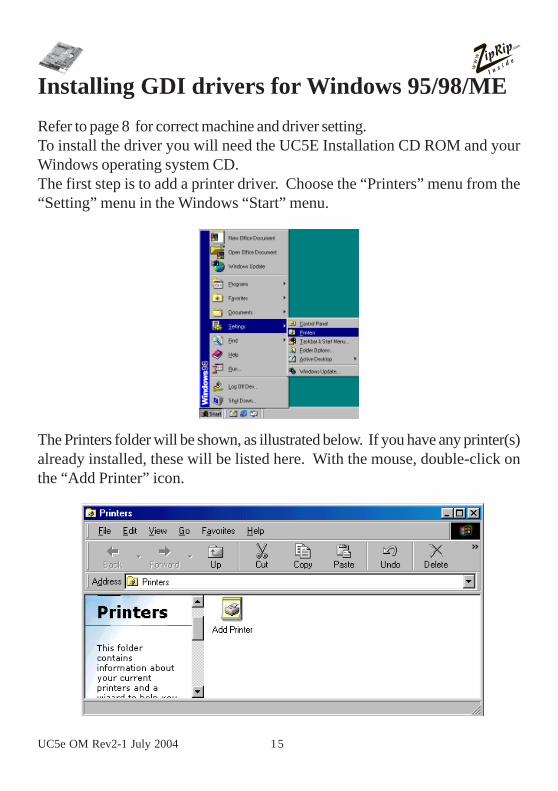
Installing GDI drivers for Windows 95/98/MERefer to page 8 for correct machine and driver setting.To install the driver you will need the UC5E Installation CD ROM and yourWindows operating system CD.The first step is to add a printer driver. Choose the “Printers” menu from the“Setting” menu in the Windows “Start” menu.
The Printers folder will be shown, as illustrated below. If you have any printer(s)already installed, these will be listed here. With the mouse, double-click onthe “Add Printer” icon.
16 UC5e OM Rev2-1 July 2004
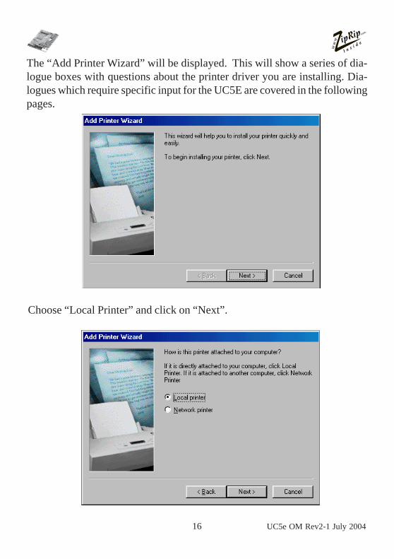
The “Add Printer Wizard” will be displayed. This will show a series of dia-logue boxes with questions about the printer driver you are installing. Dia-logues which require specific input for the UC5E are covered in the followingpages.
Choose “Local Printer” and click on “Next”.

UC5e OM Rev2-1 July 2004 17
You should now click on “Have Disk”. A dialogue box labelled “Install from Disk”will appear. Enter the location of the directory containing the UC5E printer driver.This will be on the supplied UC5E Installation CD ROM in a directory called“win95”. Select “Browse” and locate the drive that contains the UC5E CD ROM.For example, if the drive used for your CD ROM drive is “X” then enter “X:\win95”.
The following dialogue box will appear. Select the driver name that matches theDigital Duplicator you are installing the UC5E on and click “Next”. (Refer to page7 for the driver list).

18 UC5e OM Rev2-1 July 2004
The files needed for the UC5E printer driver will now be installed. Dependingon how your system is configured, you may need to insert your WindowsOperating System CD as this holds some of the files needed by the printerdriver.You now need to select the “Port” that the UC5E will be connected to. This isnormally LPT1:. If you have more than one parallel port on you PC, be sureto select the appropriate port in this dialogue. Click “Next” once the port isselected.
Enter the name that you wish the UC5E to be seen as on the computer. Click“Next” once the name has been entered.

UC5e OM Rev2-1 July 2004 19
You can now set windows to print out a test page ,once the driver is installed,to ensure that the UC5E is functioning correctly.
The UC5E printer driver will now start to install. As this is installing, youmay be prompted to insert the Windows Operating System CD. If you selected“print test page” earlier on, the UC5E should print a Windows 95/98/ME testpage.

20 UC5e OM Rev2-1 July 2004
Installing GDI drivers for Windows NT.Refer to page 8 for correct machine and driver setting.To install the printer driver you will need the UC5E Installation CD ROM aswell as the Windows NT operating system CD.The first step is to add a printer driver. Choose the “Printers” menu from the“Setting” menu in the Windows “Start” menu.
The Printers folder will be shown, as illustrated below. If you have any printer(s)already installed, these will be listed here. With the mouse, double-click onthe “Add Printer” icon.

UC5e OM Rev2-1 July 2004 21
The “Add Printer Wizard” will be displayed. This will show a series of dialogueboxes with questions about the printer driver you are installing. Dialogues whichrequire specific input for the UC5E are covered in the following pages.If you are installing the printer driver on the computer connected directly to the
UC5E, the choose “My Computer” and click “Next”. Alternatively, if you areinstalling the driver onto a machine that will be connected to the UC5E attached toanother computer over a network, then choose “Network printer server”.
If “My computer” was selected then a list of available ports will be displayed asillustrated below. Select the port you have connected the UC5E to and click“Next”. LPT1: is the most likely port to be used.
If “Network print server” was selected then a dialogue box will appear askingfor you to specify the network path of the shared printer. Enter the networkpath and continue the installation.
After defining the port to be used Windows NT displays a dialogue box listingstandard drivers supplied on the Windows NT operating system CD. The UC5E

22 UC5e OM Rev2-1 July 2004
drivers must be installed from the supplied UC5E Installation CD ROM. Click“have disk” at this dialogue box.
In the dialogue box shown enter the letter of the CD ROM drive of YOURcomputer. For example if X is the CD ROM drive letter then enter “X:\winnt4”and click “OK”.
UC5e OM Rev2-1 July 2004 23
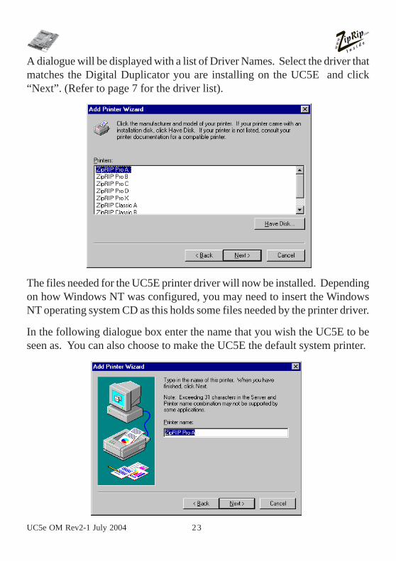
A dialogue will be displayed with a list of Driver Names. Select the driver thatmatches the Digital Duplicator you are installing on the UC5E and click“Next”. (Refer to page 7 for the driver list).
The files needed for the UC5E printer driver will now be installed. Dependingon how Windows NT was configured, you may need to insert the WindowsNT operating system CD as this holds some files needed by the printer driver.
In the following dialogue box enter the name that you wish the UC5E to beseen as. You can also choose to make the UC5E the default system printer.

24 UC5e OM Rev2-1 July 2004
You can now choose to share the UC5E over your local area network. To dothis select “Shared” and specify a suitable name for the printer to be identifiedas across the network. It is also possible to share the printer at a later stage ifrequired. Select “Next” when done.
In the final dialogue box you can specify that Windows NT prints a test pageto the UC5E once the drivers are installed. Click “Next” to continue. Thedrivers will now be installed, depending on your NT installation you may beprompted for the Windows NT installation CD. The driver should now becorrectly installed.
UC5e OM Rev2-1 July 2004 25
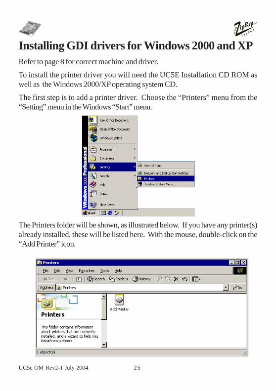
Installing GDI drivers for Windows 2000 and XPRefer to page 8 for correct machine and driver.
To install the printer driver you will need the UC5E Installation CD ROM aswell as the Windows 2000/XP operating system CD.
The first step is to add a printer driver. Choose the “Printers” menu from the“Setting” menu in the Windows “Start” menu.
The Printers folder will be shown, as illustrated below. If you have any printer(s)already installed, these will be listed here. With the mouse, double-click on the“Add Printer” icon.

26 UC5e OM Rev2-1 July 2004
The “Add Printer Wizard” will be displayed. This will show a series of dialogueboxes with questions about the printer driver you are installing. Dialogues whichrequire specific input for the UC5E are covered in the following pages.
If you are installing the printer driver on the computer connected directly to theUC5E, the choose “Local Printer” and click “Next”. Alternatively, if you are in-stalling the driver onto a machine that will be connected to the UC5E attached toanother computer over a network, then choose “Network printer”.

UC5e OM Rev2-1 July 2004 27
If “Local printer” was selected then a list of available ports will be displayed asillustrated below. Select the port you have connected the UC5E to and click“Next”. LPT1: is the most likely port to be used.
If “Network printer” was selected then a dialogue box will appear asking foryou to specify the network path of the shared printer. Enter the network pathand continue the installation.
After defining the port to be used, Windows 2000/XP displays a dialogue boxlisting standard drivers supplied on the Windows 2000/XP operating systemCD. The UC5E drivers must be installed from the supplied UC5E InstallationCD ROM. Click “have disk” at this dialogue box.

28 UC5e OM Rev2-1 July 2004
In the dialogue box shown enter YOUR CD ROM Drive Letter eg “D:\” andclick “OK”.
A dialogue will be displayed with a list of driver names (Refer to the driver liston page 8 for the model of machine you are installing onto). Select the model thatmatches the Digital Duplicator you are installing the UC5E on and click “Next”.
The files needed for the UC5E printer driver will now be installed. Depending onhow Windows 2000/XP was configured, you may need to insert the Windows2000/XP operating system CD as this holds some files needed by the printer driver.

UC5e OM Rev2-1 July 2004 29
In the following dialogue box enter the name that you wish the UC5E to be seenas. You can also choose to make the UC5E the default system printer.
You can now choose to share the UC5E over your local area network. To do thisselect “share as” and specify a suitable name for the printer to be identified asacross the network. It is also possible to share the printer at a later stage if re-quired. Select “Next” when done.
In the next dialogue box you can specify that Windows 2000 prints a test page tothe UC5E once the drivers are installed. Click “Next” to continue. The driverswill now be installed, depending on your system specifications you may be re-quired to type a path to the UC5 drivers, or to your Win 2000/XP installation CD.The drivers should now be correctly installed.

30 UC5e OM Rev2-1 July 2004
Once the printer installation is completed the following dialog box appearsto confirm installation information. Click “Finish”.

UC5e OM Rev2-1 July 2004 31
Select “Yes” in the Digital Signature Not Found dialog box.
The newly installed printer will now be shown in the printers dialog box.

32 UC5e OM Rev2-1 July 2004
Basic Operation of the UC5E.After you have completed all the installation procedures and loading of therelevent driver for the Digital Duplicator you are printing to, the UC5E isready for use.
Powering the UC5E on.The power for the UC5E comes from the Digital Duplicator. When the Dig-ital Duplicator is switched on the UC5E is switched on. If the ZipRip Pro Aand B have been installed, the right RED indicator on the UC5E keypad willbe on.
Powering the UC5E off.The power for the UC5E comes from the Digital Duplicator. When the Dig-ital Duplicator is switched off the UC5E is switched off. If the ZipRip Pro Aand B have been installed, the right RED indicator on the UC5E keypad willbe off.
Printing to the UC5E.To print to the UC5E, select the print option from the file menu of your appli-cation. In the print dialogue window select the ZipRip driver you have in-stalled (NB if you are unsure as to which machine model you have, refer to theGeneric Driver List on page 8 of this manual) and the quantity you wish toprint. In the properties section, in the print dialogue box, you can choosewhat size paper you are printing on and select a paper tray, if your machinesupports this feature. Once you have made your selection press “print” or“OK”, depending on the application. The file is processed by your computerand transfered to the UC5E. For installations on the ZipRip Pro A and B, theLEFT RED indicator light on the UC5E keypad will flash rapidly indicating itis receving and processing your file. For installations on the ZipRip Pro X theLED on the front of the Digital Duplicator will flash. (Refer to your machineoperating manual for the name and position of this LED). Once this is com-plete your Digital Duplicator will cut a master and print the quantity you havespecified.

UC5e OM Rev2-1 July 2004 33
Reset Button.
This button is located on the UC5E keypad. It is the “R” button. If youwish to reset your UC5E without switching the machine off then you canpress the “R”.
Test Button.
This button is located on the UC5E keypad. It is the “T” button. If youwish to check that the UC5E is operating correctly press the “T” and theDigital Duplicator will cut a master and print test pages. Please refer topage 10 of this manual for the full test page description.
Please Note:If you have installed the UC5E on the ZipRip Pro X range of machinesthe UC5E KEYPAD is not accessible.

34 UC5e OM Rev2-1 July 2004
Frequently Asked QuestionsQ: How far can I have the Digital Duplicator from the Computer?A: The official specification allows for 6 feet (appro. 2 metres) cable.This cable is supplied with the UC5E.Q: How many computers can you run from the UC5E?A: One IBM or compatible connected to the parallel port.
Q: Will the UC5E work with a laptop or notebook computer?A: Yes, all computers connect to the UC5E as if it were a standard
computer printer. The GDI driver will need to be installed in eachcomputer.
Q: How much RAM memory does the UC5E have?A: It comes standard with a maximum 16 megabytes RAM.
Q: What if my file size is over 1 megabyte? Will the UC5E be ableto print the file?
A: Yes, the UC5E is not limited by your file size. If your PC can processthe file, the UC5E can print it to the Digital Duplicator.
Q: Can you add additional memory?A: No, the UC5E comes with maximum memory installed as standard. If
you wish to improve the speed of the UC5E then upgrade your comput-ers RAM, processor or parallel port.
Q: Must you configure all software when you install the UC5E?A: No. Once the driver is installed in any operating system on the com-
puter, all software application programs can use it.
Q: Will the UC5E work with Windows 3.11 Windows 95? Windows98? Windows ME? Windows NT? Windows 2000?
A: Yes. Printer drivers must be installed for each operating system.

UC5e OM Rev2-1 July 2004 35
Q: Will the UC5E work with all application software programs?A: The customised printer drivers provided allow all Windows 3.11, Win-
dows 95, Windows 98, Windows ME, Windows NT, and Windows2000 programs to send documents to the UC5E.
Q: What fonts are built into the UC5E?A: None. True Type fonts installed on your operating system will print
to the UC5E.Q: Will the UC5E allow the Digital Duplicator to create an A3 / 11” x
17” image?A: Yes, as long as the Digital Duplicator model has the image output
capability.Q: Can you combine two A4 / US Letter pages side by side into a single
A3 / 11” x 17” image?A: No. The laying out of two pages A4 / US Letter has to be done in the
software where you are sending the image from.Q: Can you reverse scan with the Controller and the Digital Duplica-
tor?A: No.Q: Can you set the number of copies to print from the computer?A: Yes, all the newer Digital Duplicator models allow you to set the copy
count from your computer.Q: If I have a software or hardware question, who do I call?A: Your local sales/service organisation should be contacted first or con-
nect to the web site www.ziprip.com.Q: I have entered a custom page size but the print job comes out too
small?A: It is possible that you have input the page size incorrectly. The Unit
of measurement used for page size is 0.01 inches or 0.1 mm. Thismeans that you need to multiply by a factor of 100 to get the correctsize in inches or a factor of 10 to get the correct size in mm.

36 UC5e OM Rev2-1 July 2004
Q: The image I am getting is larger than it should be and has fine hori-zontal lines running through it?
A: It is possible that you have entered a page size greater than the maxi-mum image area of the Digital Duplicator connected to the UC5E.Check the maximum page size of your Digital Duplicator and the pagesize entered in the UC5E. Also check that you have used the correctmultiplication factor for your page measurements. (see FAQ above)
Q: When I define a custom page size the image I get is printed trans-verse (across) the drum.
A: The “width” value in the page setup refers to the size of the leadingedge of the page. The leading edge is the edge that feeds into theDigital Duplicator. The “length” value refers to the size of the sideof the page. By entering a “width” value greater than the “length”value the image will be positioned transverse on the drum. This meansthat the operator will need to use the longest edge of the sheet as theleading edge.
Q: Missing Tabs in the Printer Properties dialogue box.A: There are two possible causes for this problem:-
1. Corrupt UC5E driver installation
2. Corrupt Windows Operating System file(s)
First try resolving the problem by reinstalling the UC5E drivers. Ifthis does not solve the problem then you will need to reinstall theWindows Operating System.
WHY?A: Certain printer installations can overwrite or modify some of the Win-
dows Operating System files used by the UC5E drivers. As a resultsome of the dialogue boxes go missing. By restoring the OperatingSystem files back to the original version the Dialogue Boxes reappearand work as normal.

UC5e OM Rev2-1 July 2004 37
Q: I keep getting a time out error printing from Windows 95.A: Increase the time out settings within the printer driver. These are found under
the details tabs in the properties window. Set “not selected” to 300 seconds.Set “transmission retry” to 9999 seconds.
If none of the above resolves your problem you can send a description ofthe error to the ZipRip web site. Please include all details such as PCspecification, Operating System, Application and version being used aswell as a detailed account of the error and any preceding events that mighthave led to it. www.ziprip.com
38 UC5e OM Rev2-1 July 2004
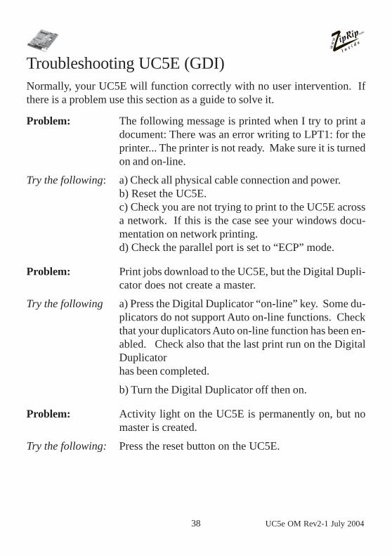
Troubleshooting UC5E (GDI)Normally, your UC5E will function correctly with no user intervention. Ifthere is a problem use this section as a guide to solve it.
Problem: The following message is printed when I try to print adocument: There was an error writing to LPT1: for theprinter... The printer is not ready. Make sure it is turnedon and on-line.
Try the following: a) Check all physical cable connection and power.b) Reset the UC5E.c) Check you are not trying to print to the UC5E acrossa network. If this is the case see your windows docu-mentation on network printing.d) Check the parallel port is set to “ECP” mode.
Problem: Print jobs download to the UC5E, but the Digital Dupli-cator does not create a master.
Try the following a) Press the Digital Duplicator “on-line” key. Some du-plicators do not support Auto on-line functions. Checkthat your duplicators Auto on-line function has been en-abled. Check also that the last print run on the DigitalDuplicatorhas been completed.
b) Turn the Digital Duplicator off then on.
Problem: Activity light on the UC5E is permanently on, but nomaster is created.
Try the following: Press the reset button on the UC5E.

UC5e OM Rev2-1 July 2004 39
Contact Local Dealer:
Web contact:- For further FAQ’s and downloads visitwww.ziprip.com