Installation manual Residental door EXT with tensional springs · Installation manual Residental...
26
Installation manual Residental door EXT with tensional springs Rev: 1530 T09-080-10-0022
Transcript of Installation manual Residental door EXT with tensional springs · Installation manual Residental...

V 1530
Installation manual Residental door EXT with tensional springs
Rev: 1530 T09-080-10-0022
V 1530 2
ABOUT THESE INSTRUCTIONS About These Instructions The following instructions include text sections, but also an illustrated section showing the main installation steps. The illustrated section can be found in section installation guide of this document.
These instructions are original instructions as described in the EC Directive 2006/42/EC. They contain im-portant information regarding the product. Please read and follow the instructions attentively. Pay particular attention to all safety and warning notices.
Keep these instructions in a safe place for further reference!
Warnings used
The general warning symbol indicates a danger that can lead to injury or death. In the text, the general warning symbol will be used with the caution levels described below.
WARNING
Indicates a potentially hazardous situation which, if not avoided, could result in death or serious injuries.
NOTICE
Indicates a potentially hazardous situation which, if not avoided, could result I n damage or destruction of the product.
V 1530 3
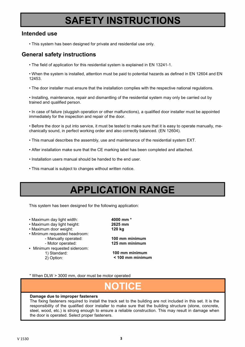
NOTICE Damage due to improper fasteners The fixing fasteners required to install the track set to the building are not included in this set. It is the responsibility of the qualified door installer to make sure that the building structure (stone, concrete, steel, wood, etc.) is strong enough to ensure a reliable construction. This may result in damage when the door is operated. Select proper fasteners.
APPLICATION RANGE
• Maximum day light width: • Maximum day light height: • Maximum door weight: • Minimum requested headroom: - Manually operated: - Motor operated: • Minimum requested sideroom: 1) Standard: 2) Option:
4000 mm * 2625 mm 120 kg 100 mm minimum 125 mm minimum 100 mm minimum < 100 mm minimum
This system has been designed for the following application:
* When DLW > 3000 mm, door must be motor operated
SAFETY INSTRUCTIONS Intended use
• This system has been designed for private and residential use only.
General safety instructions • The field of application for this residential system is explained in EN 13241-1. • When the system is installed, attention must be paid to potential hazards as defined in EN 12604 and EN 12453. • The door installer must ensure that the installation complies with the respective national regulations. • Installing, maintenance, repair and dismantling of the residential system may only be carried out by trained and qualified person. • In case of failure (sluggish operation or other malfunctions), a qualified door installer must be appointed immediately for the inspection and repair of the door. • Before the door is put into service, it must be tested to make sure that it is easy to operate manually, me-chanically sound, in perfect working order and also correctly balanced. (EN 12604). • This manual describes the assembly, use and maintenance of the residential system EXT. • After installation make sure that the CE marking label has been completed and attached. • Installation users manual should be handed to the end user. • This manual is subject to changes without written notice.

V 1530 4
INSTALLATION GUIDE
WARNING Danger of injury as the result of structural modifications Modifying or removing functional parts may put important safety components out of action. Uncon-
trolled door movement could occur and persons or objects may be trapped and injured as a result.
-Do not modify or remove any functional parts.
-Do not attach any additional parts. The extension springs are precisely matched to the door leaf-
weight. Additional components may overload the springs.
-If equipping the door with a motor operator, pay attention to the instructions provided by the manufac-
turers of the door and a motor operator. Only use the original connections of the door manufacturer!
Before installing this system, the door opening and the building floor must be completely finished. Observe the following during installation:
• Some parts can have sharp edges. Use protective gloves.
• Make sure you can always perform your work in a stable environment.
• Make sure there is enough light.
• When performing installation or maintenance, always wear at least gloves and safety boots.
• When drilling or cutting always wear safety goggles.
• Only use appropriate tools.
• Ensure adequate water run-off in the area of the bottom seal and the frame parts.
To ensure simple and secure installation, please follow the work steps listed in the illustrated
section.
WARNING Danger due to high tension Springs are under high tension and may discharge high forces if they are not secured during tensioning. Fix the door leaf in safe way in fully open position before tensioning the springs.
Each time the door is maintained, the tension of the springs should be checked and, if necessary, sub-sequently re-adjusted.
DISMANTLING INSTRUCTIONS Dismantling can only be performed by a qualified service providers and competent service technicians.

V 1530 5
Manual = 100 Min Motor = 125 Min
DLH ≤ 2625
DLH + 575
DLH - 35
165
140
FREE HEIGHT Manual: DLH - 350 Motor: DLH
Minimum load = 100 kg DLW > 3000 or DLH > 2500 Minimum load = 100 kg
General dimensional requirements:

V 1530 18
DLW + 40
≥100
DLW + 40
≤100
STANDARD
OPTION 1
General dimensional requirements/Dimensions générales requises/ Allgemeine Maßanforderungen/Základní rozměry/
80mm
40mm 30mm (HOLE)
DLW + 40
≤100 OPTION 2
V 1530 19
13 mm
13mm
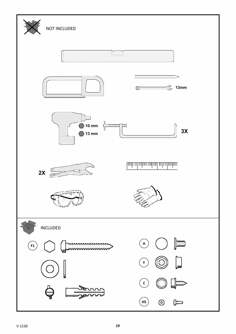
NOT INCLUDED
10 mm
F1 H
Y
C
H5
INCLUDED
2X
3X

V 1530 20
1
1.1
Y
OPTION/OPTIONAL/ALTERNATIVA
H
1.3
2.1
2
2.2
< 25mm H5
H5
1.2
> 0mm
OPTION/OPTIONAL/ALTERNATIVA

V 1530 21
OR
3
3.1 3.2
H Y
60mm
2.3
C
2.5
> 0mm
2.4
C
OPTION/OPTIONAL/ALTERNATIVA

V 1530 22
3.3
4
4.1 4.2
H
> 0mm
Y

V 1530 23
5
4.3
5.1 5.2
5.2 - 5.3 5.4 5.4
F1 > 150mm
5.4
F1
5.3
> 150mm F1
DLW / 2
DLW / 2
DLW / 2 DLW / 2
DLW / 3 DLW / 3 DLW / 3
DLW < 3000mm
DLW ≥ 3000mm
5.4 5.4
DLW < 3000mm
OPTION/OPTIONAL/ALTERNATIVA

V 1530 24
6
6.1 6.2
F1
7
7.1
H
Y
6.2
6.2
6.2
6.2
6.2
6.2
6.3 6.4
H Y
F1
OPTION OPTION/OPTIONAL/ALTERNATIVA OPTION/OPTIONAL/ALTERNATIVA

V 1530 25
7.4
H
7.2
H
Y
7.3
H
Y
H
H
Y
OPTION/OPTIONAL/ALTERNATIVA

V 1530 26
9
H Y H Y
9.1
8
8.1 8.2
8.3
F1

V 1530 27
< 500mm
10
a = b
a b
10.1
11
Y
H F1
11.1
< 1000mm
DLW > 3000mm OR DLH > 2500mm
F1 F1
H Y
OPTION/OPTIONAL/ALTERNATIVA

V 1530 28
12
< 500mm < 1000mm
H Y
H
Y
F1
12.1
Minimum load = 100kg Minimum load = 100kg
= =
13
13.1
OPTION/OPTIONAL/ALTERNATIVA

V 1530 29
13.2 13.3
13.4 13.5
C
14
1 2 3 4
a = b
a b
13.6 13.7
14.1
C
1 2 3 4 5

V 1530 30
14.2 14.3
14.4 14.5
C
C
a b
14.6
14.7 14.8
C
2X
1X
10mm
5mm
14.2 14.2
a = b
1 2 3 4
1 2 3 4 5
V 1530 31
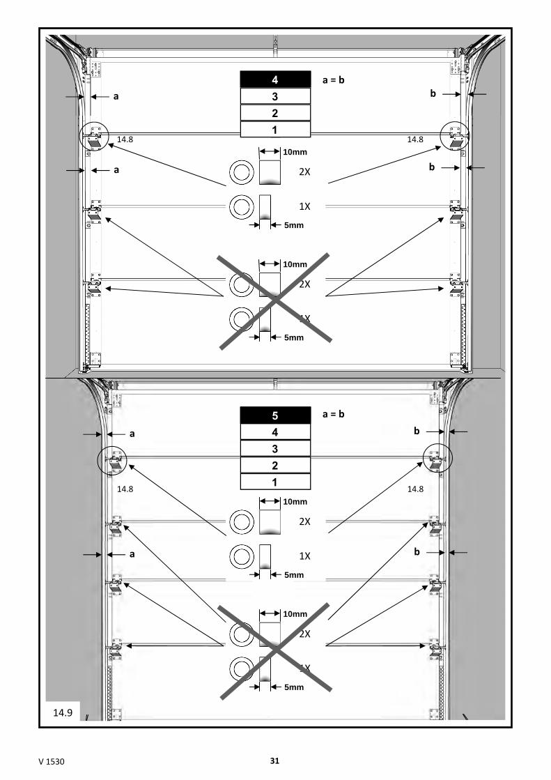
14.8 14.8 1 2 3 4
a b
a b
a = b
2X
1X
10mm
5mm
2X
1X
10mm
5mm
14.8 14.8
a b
a b
a = b
14.9
2X
1X
10mm
5mm
2X
1X
10mm
5mm
1 2 3 4 5

V 1530 32
15.3
15.1
15.2
15
15.4
C

V 1530 33
4x C
16
17
≥ 2mm AND ≤ 3mm

V 1530 34
18
18.1
18.2 18.3
18.4

V 1530 35
18.5
C
18.7
See door label information/ Voir informa�on
Siehe Information auf dem Torschild/
Viz informace na štítku vrat/
18.6
15 14 13 12 11 10 9 8 7 6 5 4 3 2 1 0

V 1530 36
19.1
19
20.1
20
21.1
21

V 1530 37
OPERATION
WARNING Danger of injury during door travel The sectional door closes to the bottom vertically; persons or objects may be trapped.
-When operating, make sure that neither persons, children in particular, nor objects are located within
the door's area of travel.
-Always keep the opening area of the door clear.
WARNING Danger of injury due to improper operation
Persons or objects may be trapped if the door is operated improperly.
-Only open and close the door using the supplied operating elements; these ensure a controlled,
smooth action.
The door must only be operated by properly instructed persons. If the sectional door is adequately assembled and inspected, it can be easily operated and moved.
Operating the door
Power operated doors The automation of a sectional door requires that special safety regulations be observed. Consult your door
operator supplier.
PARTS EXPOSED TO WEAR AND TEAR TO BE Mandated Test: Durability test conducted at SP. The worst case scenario was tested = MAX door weight of 120 kg.
The following parts listed below have to be replaced during the product’s expected lifetime:
After 25,000 cycles: • Springs
• Lifting cables
Read the User Manual supplied by manufacturer or door supplier before usage.

V 1530 41
http://door-documents.com/en/guardy-installation-manual-ext
Olav
Fasadelogo
Olav
HD Sol