Installation Instructions/Operation and Maintenance Manual
20
EdgeSafe® Smart Gate Series 1 © 2021 PS Industries ® Incorporated. All Rights Reserved. Rev021721 IMPORTANT! Read entire Instruction and Operations Manual to become familiar with the product. NOTICE This product is designed to work with the EdgeSafe® Single Gates. The effectiveness of the product is directly related to the proper installation and operation of this product. Failure to properly maintain this product will affect performance. Publication Notice This manual has been compiled and published covering the latest product descriptions and specifications. The contents of this manual and the specifications of this product are subject to change without notice. PS Safety Access TM reserves the right to make changes without notice in the specifications and materials contained herein and shall not be responsible for any damages (including consequential) caused by reliance on the materials presented, including but not limited to typographical and other errors relating to the publication. PS Safety Access and/or its respective suppliers may make improvements and/or changes in the product(s)/ service(s) offered and/or the program(s) at any time without notice. Retain this manual for future reference. If you would like a copy of this manual, please send an email to [email protected] Product registration is an essential step to protecting your product, register Online at psindustries.com/contact/register-your-product/ Mail PS Safety Access 1150 South 48th Street Grand Forks, ND 58201 Website pssafetyaccess.com Email [email protected] Local Phone 701.746.4519 Toll Free Phone 877.446.1519 Hours of Operation 8 A.M. to 5 P.M. CT Monday – Friday Contact Information PN 515218 A Installation Instructions/Operation and Maintenance Manual Patent Pending Table of Contents: Safety Precautions ............................................................. 2 Product Information ........................................................... 2 Size Reference Drawing ..................................................... 4 Installation Instructions ..................................................... 5 Disassembling of Gate..................................................... 12 Operation .......................................................................... 14 Replacement Parts List ................................................... 15 Inspection and Maintenance........................................... 18 Warranty Certificate ......................................................... 19 Models: ESG-60-PCY ESG-96-PCY ESG-120-PCY ESG-144-PCY
Transcript of Installation Instructions/Operation and Maintenance Manual

EdgeSafe® Smart Gate Series 1© 2021 PS Industries® Incorporated. All Rights Reserved.
Rev021721
IMPORTANT! Read entire Instruction and Operations Manual to become familiar with the product.
NOTICE This product is designed to work with the EdgeSafe® Single Gates. The effectiveness of the product is directly related to the proper installation and operation of this product. Failure to properly maintain this product will affect performance.
Publication NoticeThis manual has been compiled and published covering the latest product descriptions and specifications.
The contents of this manual and the specifications of this product are subject to change without notice.
PS Safety AccessTM reserves the right to make changes without notice in the specifications and materials contained herein and shall not be responsible for any damages (including consequential) caused by reliance on the materialspresented, including but not limited to typographical and other errors relating to the publication.
PS Safety Access and/or its respective suppliers may make improvements and/or changes in the product(s)/service(s) offered and/or the program(s) at any time without notice.
Retain this manual for future reference.If you would like a copy of this manual, please send an email to [email protected]
Product registration is an essential step to protecting your product, register Online at psindustries.com/contact/register-your-product/
MailPS Safety Access
1150 South 48th StreetGrand Forks, ND 58201
Websitepssafetyaccess.com
Local Phone701.746.4519
Toll Free Phone877.446.1519
Hours of Operation8 A.M. to 5 P.M. CT
Monday – Friday
Contact Information
PN 515218 A
Installation Instructions/Operation and Maintenance ManualPatent Pending
Table of Contents:Safety Precautions ............................................................. 2Product Information ........................................................... 2Size Reference Drawing ..................................................... 4Installation Instructions ..................................................... 5Disassembling of Gate .....................................................12Operation ..........................................................................14Replacement Parts List ...................................................15Inspection and Maintenance...........................................18 Warranty Certificate .........................................................19
Models: ESG-60-PCY ESG-96-PCYESG-120-PCY ESG-144-PCY

EdgeSafe® Smart Gate Series2
Rev021721
© 2021 PS Industries® Incorporated. All Rights Reserved.
Safety Precautions
Product Information
The following icons are used throughout this Manual.
DANGER Indicates an imminently hazardous situation which, if not avoided, will result in death or serious injury. WARNING Indicates a potentially hazardous situation which, if not avoided, could result in death or serious injury. CAUTIONCAUTION Indicates a potentially hazardous situation which, if not avoided, may result in minor or moderated injury.
NOTICE Indicates manufacturer’s statement of additional information.IMPORTANT! Indicates a required action.CRITICAL Indicates a vital component to product performance.
NOTICE Unauthorized modification of or to the Product voids this Limited Warranty. Authorized modifications, received in writing from PS Industries® Incorporated, as long as the modification is accomplished in strict accordance with PS Industries’ instructions, does not void warranty. If this product is modified or altered without manufactures permission, manufacturer is no longer responsible for the product design, engineering, or performance and owner assumes all responsibility. To request product modifications contact PS Industries Incorporated, 1150 S. 48th Street, Grand Forks, ND 58201, phone 877-446-1519, email: [email protected]
I. General InformationA. This manual contains information regarding installation, operation, and maintenance of the PS Safety Access’
Smart Gate.B. PS Safety Access recommends that the owner implement a regular preventative maintenance program to
inspect and maintain the Smart Gate at a minimum, in accordance with the recommendations in this manual.
II. Operation GuidelinesA. The Smart Gate is designed to meet:
1. OSHA Railing Standard OSHA 1910.29, ANSI A1264.1-2017, Canada OHS SOR-86-304 Part II, and ISO 14122-3:2016.
B. Operation in a manner other than intended could result in damage or less than acceptable performance at time of need, for which the manufacturer will not be held responsible.
III. Safety PrecautionsA. Ensure opening is clear of all obstructions through the entire proposed travel of the Smart Gate during
operation.B. Comply with all OSHA and ANSI Safety Regulations and/or company safety policies when installing.
DANGER If installed on edge, ensure area below installation edge is blocked off from personnel during installation.
DANGER Ensure mounting surface is capable of supporting all loading. Structural analysis of mounting surface is the responsibility of the owner.
IMPORTANT! Verification of the structural sufficiency of supplied anchors based on site specific conditions and the existing structure is the responsibility of the installer/customer. Refer to the anchor manufacturer’s installation instructions for installation requirements.
IV. Storage Prior to Installation of ProductA. Store materials in a dry, ventilated location. If outdoor storage is required, block materials and tarp in a tent-like
arrangement, elevated above the product with open sides to allow airflow.
V. Installation Site PreparationNOTICE Before starting site preparation and installation of the Smart Gate, read the entire Operation and
Maintenance Manual and review Approved for Construction Drawings and all additional installation instructions thoroughly. A. Clear work area of any debris.B. Ensure you have the necessary tools available.C. Obtain all required permits.

EdgeSafe® Smart Gate Series 3© 2021 PS Industries® Incorporated. All Rights Reserved.
Rev021721
Product Information
D. Personnel: Determine the appropriate number of personnel required to perform installation and have them readily available at the project site.
E. Ensure all installation personnel utilize appropriate fall protection equipment and procedures during installation.
VI. Recommended Tools for Installation:A. Tools:
1. One (1) Drill for Anchoring2. Two (2) 9/16” Socket and Ratchets3. Two (2) 1/2” Socket and Ratchets4. Two (2) 7/16” Socket and Ratchets5. One (1) Rubber Mallet6. One (1) Tape Measure7. One (1) 3/16” Allen Wrench
VII. Smart Gate Parts List A. Review inventory to ensure all parts are present for assembly/installation. Refer to parts list below.
ITEM # DESCRIPTION QTY1 ESG;GATE POST PCY 12 ESG;GATE CATCH PCY 13 ESG;ADJ CLEVIS PCY 14 ESG;2” UPR ARM PCY 15 ESG;2” LWR ARM PCY 16 ESG;1.75” UPR ARM PCY 17 ESG;1.75” LWR ARM PCY 18 ESG;GATE END PCY 19 ESG;DAMPENER # W/ ENDS *
10 ESG;HARDWARE BAG 111 ESG;TOE BOARD KIT ~1
Smart Gate Part List(As Shipped)
*Quantity is dependent on Gate Size.~Available Options: To Order Contact PS Safety Access
at 877.446.1519
Not to Scale: Shipped in Hardware Bags
218
3
9
4
6
7 5
10
9
~Optional Toe Board Kit11

EdgeSafe® Smart Gate Series4
Rev021721
© 2021 PS Industries® Incorporated. All Rights Reserved.
Size Reference Drawing
DETAIL A8”
3/4”3/4”
8”3 /
4”3 /
4”
FRONT VIEW
22 3 /
8” 43 5 /
16” M
IN.
CLEA
RAN
CE H
EIGH
T
EQUAL DIM.EQUAL DIM.
Centerline
CLEAR OPENING WIDTH
TOP VIEW
A
ESG Size Reference Table
GATE MODELCLEAR
OPENING WIDTH
CLEARANCE HEIGHT
OVERALL GATE WIDTH
*ESG-60-PCY
48” 95 1/2” 64”54” 101 1/2” 70”60” 107 1/2” 76”66” 113 1/2” 82”72” 119 1/2” 88”78” 125 1/2” 94”
*ESG-96-PCY84” 131 1/2” 100” 96” 153 1/2” 112”
108” 164 1/2” 124”
ESG-120-PCY108” 164 1/2” 124”120” 176 1/2” 136”132” 188 1/2” 148”
ESG-144-PCY132” 188 1/2” 148”144” 200 1/2” 160”156” 212 1/2” 172”
*Toe Board Kits on these models reduce clear opening by 5 1/2”, refer to chart in Toe Board O&M for dimensions.
VIII. ESG Size Reference Drawing
8”8”
OVERALL GATE WIDTH

EdgeSafe® Smart Gate Series 5© 2021 PS Industries® Incorporated. All Rights Reserved.
Rev021721
Installation
IX. Smart Gate Installation A. Refer to parts list on Page 3 for part item numbers and descriptions.
NOTICE Base Plates are slotted to allow adjustment for alignment.
STEP 1. Choose your proper gate measurements from provided Size Reference Table (refer to Page 4) and measure centered across the opening.a. Mark holes for Gate Post and Catch Post; anchor with concrete floor anchors.b. Level both posts in both directions, shim anchors as required (additional washers provided by installer).c. Install the bumper shelf and grommets using supplied hardware from “Step 1” bag (as shown in
Illustration II).
CONCRETE REQUIREMENTS FOR SUPPLIED CONCRETE ANCHORS:MIN. 3000 PSI CONCRETE4” MIN. CONCRETE THICKNESS3” MIN. EDGE DISTANCE (ALL SIDES)2 3/8” MIN. EMBEDMENT DEPTH
Step 1Illustration I
Step 1Illustration II
CL
1
Centerline of Clear Opening 10.
1
2
Equal Dim.(Base Plate to )CL
Equal Dim.(Base Plate to )CL
10. 10
10. 12
10. 9
2
10. 21
43 5 /
16”
CLEA
RAN
CE H
EIGH
T
CRITICAL If existing floor structure differs, or if shimming more than 1/4”, selection of anchors to withstand service loads and meet code requirements is by installer.

EdgeSafe® Smart Gate Series6
Rev021721
© 2021 PS Industries® Incorporated. All Rights Reserved.
Installation
STEP 2. Attach Adjustable Clevis with supplied hardware from “Step 2” bag.a. Tighten bolts, bracket height will be adjusted later in installation steps.
Step 2Illustration I
STEP 3. Use rubber mallet to gently hammer flange bearings into both sides of 2” Lift Arm.a. Slide 2” Lift Arm into Adjustable Clevis and fasten with supplied hardware from “Step 3” bag.
IMPORTANT! Matching dot colors is critical for performance, as well as orientation of all EdgeSafe Smart Gate components.
Step 3Illustration I
Step 3Illustration II
1
5
10. 3
10. 7
10. 7
10. 2 3
10. 8
10. 2
10. 4
White Dotto
White Dot
NOTICE It is best practice to use the bolt as an alignment pin to be sure the flange is square to the hole.
1
White Dotto
White Dot

EdgeSafe® Smart Gate Series 7© 2021 PS Industries® Incorporated. All Rights Reserved.
Rev021721
NOTICE The 1 3/4” Lift Arms have a series of pre-drilled holes to allow for adjustable gate width. See Size Reference Table to determine available width adjustment (refer to Page 4 for Table).
NOTICE To protect the Powder Coat finish, do NOT slide beyond desired length.
STEP 4. Slide 1 3/4” Lower Lift Arm into 2” Lift Arm to the desired gate width.a. Secure gate to desired gate width using supplied hardware from “Step 4” bag.
Installation
Both fasteners are required to secure tubes together
Step 4Illustration I
Step 4Illustration II
STEP 5. Use rubber mallet to gently hammer flange bearings into both sides of 1 3/4” Lower Lift Arm.a. Align smaller opening of Gate End piece with end of Lower Lift Arm.b. Attach using supplied hardware from “Step 5” bag.
Step 5Illustration I
Step 5Illustration II
Desired Length as obtained from Size Reference Table
TOP VIEW
7
8
10. 6
10. 2
10. 8
10. 2
10. 5
Green Dotto
Green Dot
EdgeSafe® Smart Gate Series8
Rev021721
© 2021 PS Industries® Incorporated. All Rights Reserved.
4
10. 8
10. 2
Red Dotto
Red Dot
1
Red Dotto
Red Dot
Installation
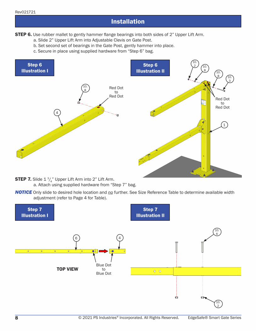
STEP 6. Use rubber mallet to gently hammer flange bearings into both sides of 2” Upper Lift Arm.a. Slide 2” Upper Lift Arm into Adjustable Clevis on Gate Post.b. Set second set of bearings in the Gate Post, gently hammer into place. c. Secure in place using supplied hardware from “Step 6” bag.
Step 6Illustration I
Step 6Illustration II
STEP 7. Slide 1 3/4” Upper Lift Arm into 2” Lift Arm.a. Attach using supplied hardware from “Step 7” bag.
NOTICE Only slide to desired hole location and no further. See Size Reference Table to determine available width adjustment (refer to Page 4 for Table).
Step 7Illustration I
Step 7Illustration II
6 4
10. 3
10. 8 10.
8
10. 6
10. 2
TOP VIEWBlue Dot
toBlue Dot

EdgeSafe® Smart Gate Series 9© 2021 PS Industries® Incorporated. All Rights Reserved.
Rev021721
STEP 8. Use bolt inserted in flange to align bearing with both holes in 1 3/4” Upper Lift Arm.a. Slide the Gate End over the 1 3/4” Upper Lift Arm.b. Secure using supplied hardware from “Step 8” bag.
Installation
Step 8Illustration I
Step 8Illustration II
NOTICE Base Plates are slotted to allow adjustment for alignment.
STEP 9. Loosen Catch Post anchors for final placement.a. Adjust the Catch Post to leave 1/4” gap from Gate End to Catch Post.b. Keep Catch Post level and tighten anchors.
DETAIL B
Step 9Illustration I
2
1/4” GAP
8
6
10. 8
10. 2
10. 5
10. 1
B B
8
Base Plate Slotted

EdgeSafe® Smart Gate Series10
Rev021721
© 2021 PS Industries® Incorporated. All Rights Reserved.
Installation
STEP 10. Add bumpers to Lower Lift Arms at both locations.a. Attach snugly with 1/4” bolts and nylock capped nuts found in “Step 10” hardware bag.
NOTICE Do NOT over-tighten, bumper should be snug but NOT compressed.
Step 10Illustration I
Step 10Illustration II
Step 11Illustration I
Step 11Illustration II
STEP 11. Open Hardware Bag “Steps 11-13” and slide Dampener Mount Link into slot in .a. Slide Dampener Mount Link into slot in 1 3/4” Lift Arm.b. Secure with one of the supplied 3/8” bolt and nylock nut from hardware bag (install in rear hole only).
Washer Location for Clear Openings:48”, 54”, or 60”
Location of Washer for all other Clear Openings
7
10. 11
10. 9
10. 15
10. 12
10. 11
10. 9
10. 12
10. 20
10. 2
10. 6
Rear Hole

EdgeSafe® Smart Gate Series 11© 2021 PS Industries® Incorporated. All Rights Reserved.
Rev021721
ESG Estimated Weight Reference TableGATE MODEL GATE WEIGHT*
ESG-60-PCY 65 LBSESG-96-PCY 86 LBS
ESG-120-PCY 94 LBSESG-144-PCY 102 LBS
Installation
Step 12Illustration I
Step 13Illustration I
Step 13Illustration II
STEP 12. With the Gate in the lowered position and resting in the Catch Post, remove the anchor nuts on the Gate Post.a. Use team lift to lay on the ground as shown for improved access during dampener installation.
NOTICE To protect the Powder Coat finish, lay on cardboard.
WARNING The Smart Gates are heavy. Verify weights and use appropriate lifting procedures and equipment.
STEP 13. Install dampener first into the Gate End with 3/8” shoulder bolt.a. Carefully assemble spacers, bolts, and nuts per images shown.
1). For ESG-60-PCY Gates refer to Illustrations I and II.2). For ESG-96/120/144-PCY Gates refer to Illustrations III and IV.
9 9
*Weight of components as shown in Illustration.
Step 13Illustration III
Step 13Illustration IV
9
10. 16
10. 13
10. 19
10. 19
10. 18
910. 17
10. 14
10. 14
10. 19
10. 16
10. 13
10. 19

EdgeSafe® Smart Gate Series12
Rev021721
© 2021 PS Industries® Incorporated. All Rights Reserved.
Installation
Step 15Illustration I
Step 16Illustration I
WARNING This step requires multiple personnel and safe lifting techniques and/or equipment as required.
STEP 14. Safely lift and place the gate on the concrete anchors, level the post, and tighten anchor nuts.a. As the gate approaches fully closed, you should hear a loud “click” noise of the dampener self-setting.
STEP 15. Visually verify that the dampener and dampener link self-set into the appropriate location.a. Insert 3/8” hex bolt and tighten nylock nut.
DANGER KEEP FINGERS CLEAR OF DAMPENER PIVOT POINTS, DAMPENER IS UNDER HIGH PRESSURE!
STEP 16. Final adjustments of Smart Gate.a. To ensure the gate opens to precisely 90º, the Adjustable Clevis needs to be set.
1). Loosen 3/8” hex bolts and nylock nuts in Adjustable Clevis (DO NOT REMOVE BOLTS).2). Tip gate vertically to 90º to re-tighten 3/8” hex bolts and nylock nuts.
b. To center Gate End into Catch Post:1). Note direction of rotation the gate is “off”.2). Raise Gate to vertical, loosen the anchor nuts, rotate the base plate an appropriate amount, tighten
nuts, and close gate to check centering.3). Repeat as necessary until Gate End falls centered into the Catch Post.
c. Place Warning decal on the top arm, in the center, facing out, for gates installed at a trip or fall hazard.
NOTICE Installer MUST apply all appropriate labels to warn of the hazards that exist beyond the gate and labels to be installed on the appropriate side.
DETAIL CC
10. 2
10. 6
Step 15Illustration II
10. 2
10. 6

EdgeSafe® Smart Gate Series 13© 2021 PS Industries® Incorporated. All Rights Reserved.
Rev021721
Installation
Step 1Illustration I
Step 4Illustration I
X. Disassembling Gate Instructions A. Only complete depressurization process if disassembling Smart Gate.
DANGER SYSTEM UNDER HIGH PRESSURE! Refer to depressurization instructions in Operation and Maintenance Manual before doing any maintenance on the gate.
STEP 1. With gate in the closed position (gate arms horizontal).a. Remove only the leading 3/8” hex bolt and nylock nut from Dampener Mount Link (as shown in
Illustration).
STEP 2. Open or lift gate to the “open” position (gate arms vertical) before proceeding with Step 3.a. You will hear a click as the link rocks out of position, this is normal during the disassembly step.
WARNING High internal gate forces! Before removing Gate Post base plate fasteners, the gate must be in the open position (gate arms vertical) so the dampener is in a non-compressed state.
STEP 3. With the Gate in the “open” position, remove the anchor nuts on the Gate Post.a. Use team lift to lay on the ground as shown for improved access during dampener installation.
NOTICE To protect the Powder Coat finish, lay on cardboard.
WARNING The Smart Gates are heavy. Verify weights and use appropriate lifting procedures and equipment.
STEP 4. Carefully remove spacers, bolts, and nuts from Dampener end.a. For ESG-60-PCY Gates refer to Illustration I.b. For ESG-96/120/144-PCY Gates refer to Illustration II.
STEP 5. Remove the 3/8” shoulder bolt, spacer(s), and nut from Dampener at Gate end.
IMPORTANT! RETURN TO INSTALLATION STEP 13 THROUGH STEP 16 (Located on pages 11 and 12), AS SHOWN IN THIS OPERATIONS AND MAINTENANCE MANUAL.
10.2
10.6
10.18
10.19
Step 4Illustration II
10.17
10.19
10. 14
10. 14

EdgeSafe® Smart Gate Series14
Rev021721
© 2021 PS Industries® Incorporated. All Rights Reserved.
Operation
OperationIllustration I
OperationIllustration II
XI. Operation
Counter-balanced design to enable easy, One-Handed operation
Uniquely placed Dampener is mounted high up to prevent potential Pallet, Forklift damage, and Pinch Points
Gate lifts vertically at a full 90º without Pinch Points
Slam-proof Dampening System allows for smooth Gate operation
Integral LOTO Hole for Safety Lock in the
Closed Position
Adjustable Clear Opening SizeHazard Safety Decal (Installed on Site)
OSHA Compliance Decal (Installed on Site)
NOTICE Installer MUST apply all appropriate labels to warn of the hazards that exist beyond the gate and labels to be installed on the appropriate side.

EdgeSafe® Smart Gate Series 15© 2021 PS Industries® Incorporated. All Rights Reserved.
Rev021721
Replacement Parts List
XII. Replacement Parts ListA. This Replacement Parts List is for all EdgeSafe™ Safety Gate Models.B. The Replacement Parts Diagrams are located on Page 16 and Page 17.
Replacement Parts ListITEM # DESCRIPTION QTY PART #
1 ESG;GATE POST PCY 1 513414
2 ESG;GATE CATCH PCY 1 513424
3 ESG;ADJ CLEVIS PCY 1 513420
4 REFER TO HARDWARE VARIANT
5 REFER TO HARDWARE VARIANT
6 REFER TO HARDWARE VARIANT
7 REFER TO HARDWARE VARIANT
8 ESG;GATE END PCY 1 513437
9 REFER TO HARDWARE VARIANT
10 ESG;HARDWARE BAG 1 514647
10.1 ANCHOR;PWRSTUD+SD1-3/8”X3”CS 8 513454
10.2 NUT;NYLOCK 3/8”16 ZN 14 501120
10.3 BOLT;HEX3/8”16X3 3/4GR5ZN 3 502934
10.4 BOLT;HEX3/8”16X3GR5ZN 1 500411
10.5 BOLT;HEX3/8”16X2 3/4GR5ZN 2 500406
10.6 BOLT;HEX3/8”16X2 1/4GR5ZN 6 500405
10.7 WASHER;FLAT 3/8”ZN 4 501947
10.8 BEARING;FLANGE STAINLESS 10 514921
10.9 BUMPER;ROUND 1-1/2”DIAX1-1/2 4 513133
10.10 BOLT;HEX 1/4”20X3 3/4GR5ZN 1 502652
10.11 BOLT;HEX 1/4”20X3 1/2GR5ZN 2 502651
10.12 NUT;NYLOCK 1/4”20 ZN NYL CAP 3 514472
10.13 SPACER;NYLON .406 X .625 X .60 2 514165
10.14 SPACER;NYLON .80X.625X .125 2 515303
10.15 WASHER;NYLON .274X.1.75X.25 1 514164
10.16 BOLT;SHOULDER 3/8”X2-1/4 1 513779
10.17 BOLT;SHOULDER 3/8”X1-1/2 1 515314
10.18 BOLT;HEX5/16”18X1GR5ZN 1 500422
10.19 NUT;NYLOCK 5/16”18 HEAVY ZN 2 513780
10.20 ESG;DAMPENER MOUNT LINK SS 1 514162
10.21 BUMPER;SBR60 1/2”x1/8” 2 515343
~11 REFER TO HARDWARE VARIANT
Finish OptionsPCY Powder Coat Safety Yellow
Hardware Variant for ESG-60-PCYITEM # DESCRIPTION QTY PART #
4 ESG;2” UPR ARM 5FT PCY 1 514158
5 ESG;2” LWR ARM 5FT PCY 1 515307
6 ESG;1.75” UPR ARM 5 FT PCY 1 514160
7 ESG;1.75” LWR ARM 5FT PCY 1 515310
9 ESG;DAMPENER 5 W/ENDS 1 514163
~11 ESG;60”TOE BOARD KIT 1 515186
Hardware Variant for ESG-96-PCYITEM # DESCRIPTION QTY PART #
4 ESG;2” UPR ARM 8FT PCY 1 513920
5 ESG;2” LWR ARM 8FT PCY 1 515308
6 ESG;1.75” UPR ARM PCY 1 513430
7 ESG;1.75” LWR ARM PCY 1 515311
9 ESG;DAMPENER 8 W/CLEVIS ENDS 2 513918
~11 ESG;96”TOE BOARD KIT 1 515187
Hardware Variant for ESG-120-PCYITEM # DESCRIPTION QTY PART #
4 ESG;2” UPR ARM 10FT PCY 1 513428
5 ESG;2” LWR ARM 10FT PCY 1 515309
6 ESG;1.75” UPR ARM PCY 1 513430
7 ESG;1.75” LWR ARM PCY 1 515311
9 ESG;DAMPENER 10 W/CLEVIS ENDS 2 513462
Hardware Variant for ESG-144-PCYITEM # DESCRIPTION QTY PART #
4 ESG;2” UPR ARM 12FT PCY 1 513726
5 ESG;2” LWR ARM 12FT PCY 1 515312
6 ESG;1.75” UPR ARM PCY 1 513430
7 ESG;1.75” LWR ARM PCY 1 515311
9 ESG;DAMPENER 12 W/CLEVIS ENDS 2 513718
~AVAILABLE OPTIONS: To Order Contact PS Safety Access.
TO ORDER PARTS CONTACT PS SAFETY ACCESS AT877.446.1519 or [email protected]

EdgeSafe® Smart Gate Series16
Rev021721
© 2021 PS Industries® Incorporated. All Rights Reserved.
Replacement Parts Diagram
XIII. Replacement Parts DiagramA. These Replacement Parts Diagrams for ESG-60-PCY Models.B. The Replacement Parts List is located on Page 15.
10. 21
10. 10
10. 12
10. 5
10. 2
10. 1
10. 5
10. 210.
19
10. 16
10. 8
10. 6
10. 6
10. 2
10. 2
10. 11
10. 9
10. 12
10. 18
10. 19
10. 6
10. 2
DETAIL F
F
DETAIL EDETAIL D
D
E
10. 15
10. 9 10.
13
9
10. 3
10. 7
10. 2
10. 710.
2
10. 8
10. 4
3
10. 11
10. 20
110. 3
10. 8
10. 8
10. 2
10. 8
10. 9
8
2
7
5
6
4
10. 12

EdgeSafe® Smart Gate Series 17© 2021 PS Industries® Incorporated. All Rights Reserved.
Rev021721
Replacement Parts Diagram
XIII. Replacement Parts Diagram ContinuedA. These Replacement Parts Diagrams for ESG-96-PCY, ESG-120-PCY, and ESG-144-PCY Models.B. The Replacement Parts List is located on Page 15.
10. 17
10. 10
10. 1
10. 5
10. 2
10. 19
10. 16
10. 8
10. 6
10. 2
10. 11
10. 9
10. 12
10. 2
10. 19
10. 6
10. 20
DETAIL I
I
DETAIL HDETAIL G
G
H
10. 15
10. 9
10. 13
9
10. 3
10. 7
10. 2
10. 710.
2
10. 8
10. 4
3
10. 11
10. 5
110. 3
10. 8
10. 8
10. 2
10. 8
10. 9
8
2
7
5 6
4
10. 12
10. 8
10. 14 10.
2
10. 12
10. 21

EdgeSafe® Smart Gate Series18
Rev021721
© 2021 PS Industries® Incorporated. All Rights Reserved.
XIV. Inspection and MaintenanceA. Environmental conditions may affect the maintenance and repair requirements of the product, and
recommended preventative maintenance frequency.B. If any of the inspection items are found to not meet the standard IMMEDIATELY “TAG OUT” the EdgeSafe®
Smart Gate removing it from active use and guard the opening until repairs are completed.NOTICE PS Safety Access recommends that the owner implement a regular and preventative maintenance program
to inspect and maintain Smart Gate at a minimum, in accordance with the recommendations in the table below.
WARNING While performing maintenance and inspection ensure personnel utilize appropriate fall protection equipment and procedures.
Inspection and Maintenance
Recommended Preventative MaintenanceITEM FREQUENCY ITEM DESCRIPTION WHAT TO INSPECT STANDARD REPAIR ACTION
1 Each Use General Housekeeping Opening Opening must be kept free of debris and obstructions. Always keep area clean.
2 Weekly Gate Gate for corrosion or damage. To protect the structural integrity and provide engineered safety protection.
Touch up finishes, or refinish as necessary.
Welds Welds are intact without visible cracks or crazing.
Repair or Replace component immediately.
Gate alignment and free movement.
Gate must move freely without any interference; levelness from ground/
walking surface.Adjust gate as necessary.
3 Weekly Posts Post assemblies for corrosion or damage.
To protect the structural integrity and provide engineered safety protection.
Touch up finishes, or refinish as necessary.
Welds Welds are intact without visible cracks or crazing.
Repair or Replace component immediately.
4 Monthly Structural Attachment All Fasteners (Structural Attachment)
Fasteners must be present and be Snug Tight; connections pulled into
firm contact by the fastener, no gaps between material.
Tighten fasteners to snug tight. Replace any missing fasteners.
5 Monthly Dampener Dampener for free movement and no corrosion or damage.
Must be free of all debris, operates smoothly without interference.
Replace if damage or deterioration to Dampener has occurred. Use only Factory approved products.
Self-lubrication Must be well lubricated. Run Dampeners through full stroke length to re-lubricate.
6 Monthly Labels All labels Manufacturer's labels in place and legible.
Replace. Contact manufacturer for FREE replacement labels.

EdgeSafe® Smart Gate Series 19© 2021 PS Industries® Incorporated. All Rights Reserved.
Rev021721
Rev. 011221
PS INDUSTRIES® INCORPORATED – LIMITED WARRANTY
Limited Warranty: Subject to the terms of this Limited Warranty, PS Industries® Incorporated warrants to the original user or consumer (the “Owner”) of a PS Industries product (the “Product”) that, for a period of one (1) year from date of shipment, the Product will be free from defects in material and workmanship under normal use and service, and provided the Product is installed, operated and maintained in accordance with instructions supplied by PS Industries. The terms and limitations of this Limited Warranty apply to all repaired or replacement Products for a term equal to the balance of the warranty remaining on the Product that was repaired or replaced as of the date of such repair or replacement. Register online at: www.psindustries.com/contact/register-your-product
PS Flood BarriersTM Product Warranty Registration: For PS Flood BarriersTM Products, this Limited Warranty will only be valid if the Owner completes the Warranty Registration Form provided within thirty (30) days of Product installation. To request a copy of the Warranty Registration Form, contact PS Industries Incorporated, 1150 S. 48th Street, Grand Forks, ND 58201, phone 877-446-1519, email: [email protected]. Register online at: www.psindustries.com/contact/register-your-product/ Additional Warranty Registration Forms can be downloaded at www.psfloodbarriers.com/download-center/
Warranty Exclusions: Notwithstanding anything to the contrary, this Limited Warranty does not cover any of the following: 1. Normal wear and tear (including, but not limited to, normal wear and tear to gaskets and weather seals); damage or accidents resulting
from freight damage, from failure to follow precautionary safety measures, or applied paint failure; abuse, misuse or unauthorized modification of the Product; misapplication; improper installation; or any defects, damage or other harm that is not the result of the acts or omissions of PS Industries.
2. Cost of field labor or other charges incurred by Owner in removing and/or re-affixing the Product or any part or component thereof. 3. Transportation costs.
Unauthorized modification of or to the Product voids this Limited Warranty. Authorized modifications, received in writing from PS Industries, as long as the modification is accomplished in strict accordance with PS Industries’ instructions, does not void warranty. To request product modifications contact PS Industries, 1150 S. 48th Street, Grand Forks, ND 58201, phone 877-446-1519, email: [email protected].
Claim Procedure: To make a claim under this Limited Warranty, the claim must be received by PS Industries before the expiration of the above stated Limited Warranty period together with proof of purchase. Contact PS Industries at the address shown below.
PS Industries Incorporated Toll Free: 877-446-1519 Attention: Warranty Phone: 701-746-4519 1150 S. 48th Street Fax: 701-746-8340 Grand Forks, ND 58201 E-mail: [email protected]
An authorized PS Industries representative must be given a reasonable opportunity to inspect and investigate the alleged Product defect prior to any work being done that affects the Product or its installation. PS Industries reserves the right to charge reasonable amounts for travel and labor associated with investigation of claims. PS Industries may also require photographs of the alleged Product defect or return of the Product or part to a designated PS Industries location, freight prepaid. A return goods authorization must be received prior to the return of the Product or part. Please contact PS Industries to determine the designated location for return and to obtain the return material authorization.
Exclusive Remedy: In the event of a warranty claim that PS Industries determines to be covered by this Limited Warranty, PS Industries will replace or repair, at PS Industries’ discretion, the Product or any part of the Product found to be defective.
Disclaimers: The above warranty and remedy is the sole express warranty and remedy given by PS Industries on its Product. No warranties or representations at any time made by any representative from PS Industries shall vary or expand the provisions hereof. TO THE EXTENT PERMITTED BY LAW, ALL EXPRESS AND IMPLIED WARRANTIES (INCLUDING IMPLIED WARRANTIES OF MERCHANTABILITY, FITNESS FOR A PARTICULAR PURPOSE AND NON-INFRINGEMENT) OTHER THAN THE EXPRESS LIMITED WARRANTY SET FORTH ABOVE ARE EXPRESSLY DISCLAIMED. UPON THE EXPIRATION OF THE ABOVE STATED LIMITED WARRANTY PERIOD, ANY AND ALL APPLICABLE IMPLIED WARRANTIES, INCLUDING, WITHOUT LIMITATION, WARRANTIES OF MERCHANTABILITY, FITNESS FOR A PARTICULAR PURPOSE AND NON-INFRINGEMENT, ARE DISCLAIMED. SOME STATES DO NOT ALLOW LIMITATION ON HOW LONG AN IMPLIED WARRANTY LASTS, SO THE ABOVE LIMITATION MAY NOT APPLY TO OWNER.
LIABILITY LIMITATION: In no event will PS Industries’ liability to Owner or any other person or entity exceed the price paid to PS Industries for the defective Product. IN NO EVENT SHALL PS INDUSTRIES BE LIABLE TO OWNER OR ANY OTHER PERSON OR ENTITY FOR INCIDENTAL, CONSEQUENTIAL, INDIRECT OR SPECIAL DAMAGES OF ANY DESCRIPTION, WHETHER ARISING OUT OF WARRANTY (INCLUDING ANY IMPLIED WARRANTIES) OR ANY OTHER CONTRACT, STRICT LIABILITY, NEGLIGENCE OR OTHER TORT, OR OTHERWISE, INCLUDING ARISING FROM INSPECTION OR REMEDY DELAYS. SOME STATES DO NOT ALLOW THE EXCLUSION OR LIMITATION OF INCIDENTAL OR CONSEQUENTIAL DAMAGES, SO THE ABOVE LIMITATION AND EXCLUSION MAY NOT APPLY TO OWNER.
THIS WARRANTY GIVES OWNER SPECIFIC LEGAL RIGHTS AND OWNER MAY ALSO HAVE OTHER RIGHTS, WHICH VARY FROM STATE TO STATE.

[email protected] | pssafetyaccess.com1150 South 48th Street | Grand Forks, ND 58201
Product Registration:psindustries.com/contact/register-your-product