
Installation Instructions T-400 WICKED QUICK ... - ATI Racing
2
T-400 WICKED QUICK™ BILLET ALUMINUM TRANSBRAKE Part # 403086 P-R-N-3-2 NOTE: Brake works in both forward gears 6718 Whitestone Road • Baltimore, MD 21207 • (410) 298-4343 • FAX: (410) 298-3579 www.atiracing.com Installation Instructions (6) 5/16-18 1” Counterbore Screws (#951248) (3) 5/16-18 1½” Counterbore Screws (#951249) (3) 1/4-20 1¼” Counterbore Screws (#951441) (1) 1/4-20 3/4” Button Head Cap Screw (951066) (1) Instruction Sheet (#403086-I) (1) Wicked Quick Set-Up Notice (#919091) (1) Safety Notice (#919142) (2) Wicked Quick Decals (#Z20035) PACKING LIST (1) Billet aluminum Valve Body Assy. Includes: • Separator Plate • (2) Valve Body Gaskets #403222 • Manual Valve • 1/2” Nylon Ball (1) Solenoid with Adapter (1) Modulator Plug (1) Electrical Connector (16) HD Direct Drum Springs Accidental transbrake engagement poses a serious safety risk! You must have safety electronics in place to safeguard against accidental engagement of the transbrake solenoid when not intended. ATI can assume no responsibility for workmanship or driving procedures that are out of our control. Read all instructions carefully Failure to comply may cause extreme damage, possible explosion of the transmission and/or injury or death to the driver! For your protection, always use a transmission shield, blanket or SFI case! ** DO NOT SHUT OFF THE ENGINE WHILE IN THE TRAPS! ** VOLTS! All modifications are essential. Follow as shown! STEP 1 - High Drum Preparation of the high clutch drum is extremely important. Removal of the piston is necessary. A 1/16” inch (.063”) bleed hole is drilled through the drum in the area behind the piston. It is best to drill from the inside out placing the hole as close to the outer sealing portion as possible (big lip seal). The drill may be held at an angle for more drilling room (Figure 1). Reinstall the piston in the drum using only two (2) lip seals, the outer and the inner. Do not use the center seal! Discard the 16 original piston springs and replace with the special springs provided with this kit. HIGH 1/16” DRILL (.063) LEAVE OUT CENTER LIP SEAL! Figure 1 Note: For units running more than 250 psi, you MUST have a minimum of 14 volts at the starting line with all necessary accessories operating.
Transcript of Installation Instructions T-400 WICKED QUICK ... - ATI Racing
T-400 WICKED QUICK™BILLET ALUMINUM TRANSBRAKE
Part # 403086P-R-N-3-2
NOTE: Brake works in both forward gears
6718 Whitestone Road • Baltimore, MD 21207 • (410) 298-4343 • FAX: (410) 298-3579www.atiracing.com
Installation Instructions
(6) 5/16-18 1” Counterbore Screws (#951248)(3) 5/16-18 1½” Counterbore Screws (#951249) (3) 1/4-20 1¼” Counterbore Screws (#951441)(1) 1/4-20 3/4” Button Head Cap Screw (951066)(1) Instruction Sheet (#403086-I)(1) Wicked Quick Set-Up Notice (#919091)(1) Safety Notice (#919142)(2) Wicked Quick Decals (#Z20035)
PACKING LIST(1) Billet aluminum Valve Body Assy.Includes: • Separator Plate • (2) Valve Body Gaskets #403222 • Manual Valve • 1/2” Nylon Ball
(1) Solenoid with Adapter(1) Modulator Plug(1) Electrical Connector(16) HD Direct Drum Springs
For your protection, always use a transmission shield, blanket or SFI case!
Accidental transbrake engagement poses a serious safety risk! You must have safety electronics in place to safeguard against accidental engagement of the transbrake solenoid when not intended.
ATI can assume no responsibility for workmanship or driving procedures that are out of our control. Read all instructions carefully Failure to comply may cause extreme damage, possible explosion of the transmission and/or injury or death to the driver!
For your protection, always use a transmission shield, blanket or SFI case!
** DO NOT SHUT OFF THE ENGINE WHILE IN THE TRAPS! **
VOLTS!
All modifications are essential. Follow as shown!
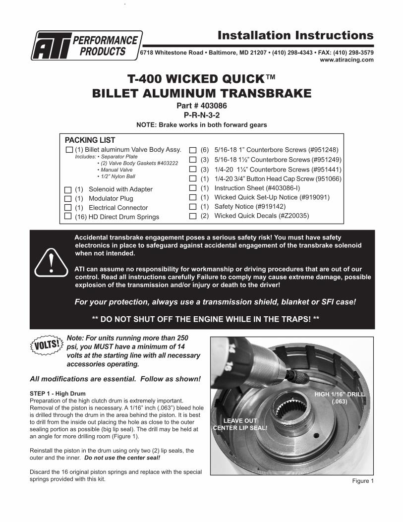
STEP 1 - High DrumPreparation of the high clutch drum is extremely important. Removal of the piston is necessary. A 1/16” inch (.063”) bleed hole is drilled through the drum in the area behind the piston. It is best to drill from the inside out placing the hole as close to the outer sealing portion as possible (big lip seal). The drill may be held at an angle for more drilling room (Figure 1).
Reinstall the piston in the drum using only two (2) lip seals, the outer and the inner. Do not use the center seal!
Discard the 16 original piston springs and replace with the special springs provided with this kit.
HIGH 1/16” DRILL (.063)
LEAVE OUT CENTER LIP SEAL!
Figure 1
Note: For units running more than 250 psi, you MUST have a minimum of 14 volts at the starting line with all necessary accessories operating.
STEP 2 - Transbrake Electrical ConnectionThis connection is activated by applying 12 (or 16) volts into the spade connector where the kickdown lever used to be in the OEM case. An SFI case will require 940340 Pass Thru Connector. Use minimum 16 gauge wire and a 20 amp fuse. Solenoid pulls about 6 to 8 Amps.
STEP 3 - Use a Stock 400 Modulator valveInspect the valve. It cannot be modified or ground in any way!
(Figure 2)
INST. # 403086 - I 5/2018
Case Preparation: Try to find a complete transmission, or an unaltered core and keep the parts together to prevent problems. This valve body requires no case modifications.
Intermediate Servo: Leave out the intermediate servo, servo spring, parts and intermediate band.
Valve Body Gaskets: Run a flat file or a whetstone over the case to remove any high spots that might cause a crossover leak and install supplied gaskets.
Manual Valve: Use supplied manual valve, dip it in clean transmission fluid and install in your ATI valve body.
Rear Servo: The rear servo is installed in the normal manner. The two (2) accumulator rings may be removed if desired. Use stock springs and parts.
PLACE BALLBETWEEN SEATS
AS SHOWN
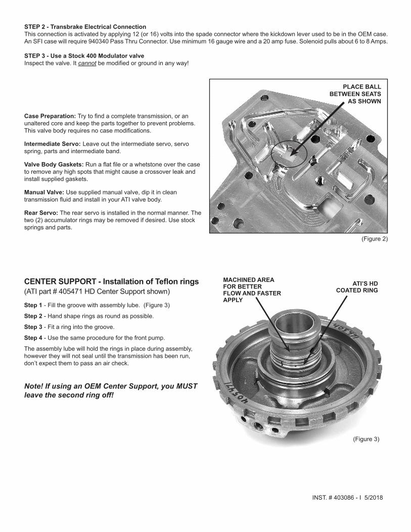
CENTER SUPPORT - Installation of Teflon rings(ATI part # 405471 HD Center Support shown)
Step 1 - Fill the groove with assembly lube. (Figure 3)
Step 2 - Hand shape rings as round as possible.
Step 3 - Fit a ring into the groove.
Step 4 - Use the same procedure for the front pump.
The assembly lube will hold the rings in place during assembly, however they will not seal until the transmission has been run, don’t expect them to pass an air check.
Note! If using an OEM Center Support, you MUST leave the second ring off!
MACHINED AREA FOR BETTER FLOW AND FASTER APPLY
ATI’S HD COATED RING
(Figure 3)