INSTALLATION INSTRUCTIONS REMOTE OIL TANK KIT … · INSTALLATION INSTRUCTIONS REMOTE OIL TANK KIT...
8
DSS05141I 1 of 8 Printed in the United States. © 2006 BRP US Inc. All rights reserved. TM, ® Trademarks and registered trademarks of Bombardier Recreational Products Inc. or its affiliates. INSTALLATION INSTRUCTIONS REMOTE OIL TANK KIT APPLICATION This instruction sheet is a guide for proper installation of components supplied in this kit. These components are designed for use on Evinrude and Johnson outboards. Refer to service manual and installation guides for additional assembly information. SAFETY INFORMATION For safety reasons, this kit should be installed by an authorized Evinrude ® /Johnson ® dealer. This instruction sheet is not a substitute for work experience. Additional helpful information may be found in other service literature for your engine. This instruction sheet uses the following signal words identifying important safety messages. IMPORTANT: Identifies information that will help prevent damage to machinery and appears next to information that controls correct assembly and op- eration of the product. These safety alert signal words mean: ATTENTION! BECOME ALERT! YOUR SAFETY IS INVOLVED! Always follow common shop safety practices. If you have not had training related to common shop safety practices, you should do so to protect yourself, as well as the people around you. It is understood that this instruction sheet may be translated into other languages. In the event of any discrepancy, the English version shall prevail. DO NOT do any repairs until you have read the in- structions and checked the pictures relating to the re- pairs. Be careful, and never rush or guess a service procedure. Human error is caused by many factors: carelessness, fatigue, overload, preoccupation, unfamiliarity with the product, and drugs and alcohol use, to name a few. Damage to a boat and outboard can be fixed in a short period of time, but injury or death has a lasting effect. When replacement parts are required, use Evinrude/ Johnson Genuine Parts or parts with equivalent char- acteristics, including type, strength and material. Us- ing substandard parts could result in injury or product malfunction. Torque wrench tightening specifications must be strictly followed. Replace any locking fastener (lock- nut or patch screw) if its locking feature becomes weak. Definite resistance to turning must be felt when reusing a locking fastener. If replacement is specified or required because the locking fastener has become weak, use only authorized Evinrude/Johnson Genu- ine Parts. If you use procedures or service tools that are not recommended in this instruction sheet, YOU ALONE must decide if your actions might injure people or damage the outboard. TO THE INSTALLER: Give this sheet to the owner. Advise the owner of any special operation or mainte- nance information contained in the instructions. TO THE OWNER: Save these instructions in your owner’s kit. This document contains information im- portant to the future use and maintenance of your en- gine. DANGER Indicates an imminently hazardous situa- tion which, if not avoided, WILL result in death or serious injury. WARNING Indicates a potentially hazardous situation which, if not avoided, CAN result in severe injury or death. CAUTION Indicates a potentially hazardous situation which, if not avoided, MAY result in minor or moderate personal injury or property damage. It also may be used to alert against unsafe practices.
Transcript of INSTALLATION INSTRUCTIONS REMOTE OIL TANK KIT … · INSTALLATION INSTRUCTIONS REMOTE OIL TANK KIT...

INSTALLATION INSTRUCTIONSREMOTE OIL TANK KIT
APPLICATIONThis instruction sheet is a guide for proper installation of components supplied in this kit. Thesecomponents are designed for use on Evinrude and Johnson outboards. Refer to service manual andinstallation guides for additional assembly information.
SAFETY INFORMATIONFor safety reasons, this kit should be installed byan authorized Evinrude®/Johnson® dealer. Thisinstruction sheet is not a substitute for workexperience. Additional helpful information may befound in other service literature for your engine.This instruction sheet uses the following signal wordsidentifying important safety messages.
IMPORTANT: Identifies information that will helpprevent damage to machinery and appears next toinformation that controls correct assembly and op-eration of the product.
These safety alert signal words mean:ATTENTION!BECOME ALERT!YOUR SAFETY IS INVOLVED!
Always follow common shop safety practices. If youhave not had training related to common shop safetypractices, you should do so to protect yourself, aswell as the people around you.It is understood that this instruction sheet may betranslated into other languages. In the event of anydiscrepancy, the English version shall prevail.DO NOT do any repairs until you have read the in-structions and checked the pictures relating to the re-pairs.Be careful, and never rush or guess a serviceprocedure. Human error is caused by many factors:carelessness, fatigue, overload, preoccupation,unfamiliarity with the product, and drugs and alcoholuse, to name a few. Damage to a boat and outboardcan be fixed in a short period of time, but injury ordeath has a lasting effect.When replacement parts are required, use Evinrude/Johnson Genuine Parts or parts with equivalent char-acteristics, including type, strength and material. Us-ing substandard parts could result in injury or productmalfunction.Torque wrench tightening specifications must bestrictly followed. Replace any locking fastener (lock-nut or patch screw) if its locking feature becomesweak. Definite resistance to turning must be felt whenreusing a locking fastener. If replacement is specifiedor required because the locking fastener has becomeweak, use only authorized Evinrude/Johnson Genu-ine Parts.If you use procedures or service tools that are notrecommended in this instruction sheet, YOU ALONEmust decide if your actions might injure people ordamage the outboard.TO THE INSTALLER: Give this sheet to the owner.Advise the owner of any special operation or mainte-nance information contained in the instructions.TO THE OWNER: Save these instructions in yourowner’s kit. This document contains information im-portant to the future use and maintenance of your en-gine.
DANGER
Indicates an imminently hazardous situa-tion which, if not avoided, WILL result indeath or serious injury.
WARNING
Indicates a potentially hazardous situationwhich, if not avoided, CAN result in severeinjury or death.
CAUTION
Indicates a potentially hazardous situationwhich, if not avoided, MAY result in minoror moderate personal injury or propertydamage. It also may be used to alertagainst unsafe practices.
DSS05141I 1 of 8
Printed in the United States.© 2006 BRP US Inc. All rights reserved.TM, ® Trademarks and registered trademarks of Bombardier Recreational Products Inc. or its affiliates.

OIL TANK – 1.8 GALLON
3
4
2
1
7
6
9
8
1110
5
15
16
12
13
14
17 18
19
20
28
27
26
2524
222123 24
21
26
2930
33
31
32
3435
EPC3374
Ref P/N Name of Part Qty Ref P/N Name of Part Qty- 177284 OIL TANK. Assy, 1.8 Gallon New 1 18 176295 **CONNECTOR, 2-pin 11 176712 *OIL TANK 1 19 514788 ***SEAL, 2-socket 12 127670 *COVER, Oil tank 1 20 127287 **LOCK WEDGE, 2-socket 13 176217 *CAP ASSEMBLY 1 21 126945 **CLAMP, Band, small 24 123231 **GASKET, Cap 1 22 175985 **PRIMER BULB ASSEMBLY 15 175001 *ROD ASSEMBLY, Cover to bracket 2 23 436191 ***NIPPLE & VALVE Assy., Inlet 16 124292 *BRACKET, Mounting 1 24 553166 ***CLAMP, Band, Large 27 124073 *LAG SCREW 2 25 436145 ***NIPPLE & VALVE Assy., Outlet 18 176724 *OIL RETURN ASSEMBLY 1 26 778707 **HOSE, Oil Supply A 19 125529 *SCREW 5 27 329661 **HOLDER, Plug 1
10 315391 *PLUG, Oil return fitting 1 28 347108 **CLAMP, Engine oil connector 111 320107 *TIE STRAP 1 29 512746 **CONNECTOR, 2-pin B 112 177285 *OIL TANK PICKUP KIT New 1 30 511469 **TERMINAL, Pin B 213 124485 **SCREW, Pickup Assy. to tank 4 31 510818 **TERMINAL, Ring B 114 322654 **CLAMP, Snap 1 32 512876 **TERMINAL, Socket B 115 126793 **SEAL, Pickup Assy. to tank 1 33 512947 **TERMINAL, Bullet B 116 174377 **FILTER ASSEMBLY, Oil 1 34 513185 **SLEEVE, Bullet terminal B 117 514680 **TERMINAL, Pin 2 35 513186 **SLEEVE, Socket B 1
A Cut to length from bulk rollB Use to adapt harness to older style wiring connectors
2 of 8

OIL TANK – 3.0 GALLON
22
2
3
1
4
5
6
7
8
9
10
11
12
13
14
15,16,17,18
19
1920
21
22
22
23
24
26 25
25
2728
2930
EPC3373
Ref P/N Name of Part Qty Ref P/N Name of Part Qty- 176996 OIL TANK Assy, (3.0 gallon) 1 16 514788 ***SEAL, 2-socket 11 176722 *OIL TANK 1 17 127287 **LOCK WEDGE, 2-socket 12 176217 *CAP ASSEMBLY 1 18 514680 **TERMINAL, Pin 23 123231 **GASKET, Cap 1 19 778707 **HOSE, Oil Supply A 14 121470 *LOCKNUT, Hook bolt to cross bar 2 20 347108 **CLAMP, Engine Oil Connector 15 121497 *WASHER 2 21 329661 **HOLDER, Plug 16 124694 *CROSS BAR 1 22 126945 **CLAMP, Band, small 27 124691 *HOOK BOLT 2 23 175985 **PRIMER BULB Assy. 18 124693 *BRACKET, Mounting 1 24 436145 ***VALVE, Outlet 19 124073 *LAG SCREW 2 25 553166 ***CLAMP, Band, large 2
10 176366 *OIL PICKUP Assy. 1 26 436191 ***VALVE, Inlet 111 124485 **SCREW, Pickup Assy, to tank 4 27 176724 *OIL RETURN ASSEMBLY 112 126793 **SEAL 1 28 125529 **SCREW, Oil return 513 322654 **CLAMP, Snap 1 29 315391 *PLUG 114 174377 **FILTER ASSEMBLY, Oil 1 30 320107 *TIE STRAP 115 176295 **CONNECTOR, 2-pin 1
A Cut to Length from bulk roll
3 of 8

Oil Tank LocationIMPORTANT: Consider the installation locationof the oil tank carefully. The oil tank is vented tothe atmosphere. To avoid serious powerheaddamage, be sure the oil tank is installed in a lo-cation that does not allow constant exposure tosunlight, rain, bilge water or spray.
Select mounting location which provides:• A solid place to mount the tank;• A dry location that prevents exposure to rain
or spraying water;• Access for adding oil;• Access to oil-primer bulb; and• Interference-free hose and wire routing to out-
board.
Each oil tank is originally fitted with a single oilpickup assembly with 15 ft. (4.5 m) of oil supplyhose and 17 ft. (5.2 m) of sending unit wiringharness.
If necessary, the oil tank can be mounted furtherfrom the outboard than the supplied hose andharness allow. The maximum length of oil supplyhose that can be fitted to the oil tank is 25 ft.(7.6 m).
IMPORTANT: Do not add hose to an existing oilsupply hose.
If the oil tank requires more than 15 ft. (4.5 m) ofoil supply hose:• Oil supply hose from primer bulb to outboard
must be one continuous length of 1/4 in. (6.4mm) hose.
• Maximum length for hose is 25 ft. (7.6 m).• Replacement hose must be designated for
fuel or oil use and approved for marine use.• Extend wiring harness with 16 gauge AWG
wire.• Protect connections with heat shrink tube.• Maintain wire color and polarity when extend-
ing harness.
An appropriately sized battery box may be usedto conceal and protect the oil tank, if desired.
IMPORTANT: Be sure box includes drain holesso it does not fill with water and contaminate oil.
Oil Tank MountingPlace tank in selected position. Mark one lineunder groove in tank bottom and one line at eachend of tank as shown.
WARNING
To prevent accidental starting while ser-vicing, disconnect battery leads from bat-tery. Twist and remove all spark plugleads.
Nautical Orientation
000074
1. Groove of tank2. End of tank
44737
1
2 2
4 of 8
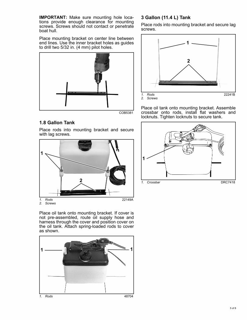
IMPORTANT: Make sure mounting hole loca-tions provide enough clearance for mountingscrews. Screws should not contact or penetrateboat hull.
Place mounting bracket on center line betweenend lines. Use the inner bracket holes as guidesto drill two 5/32 in. (4 mm) pilot holes.
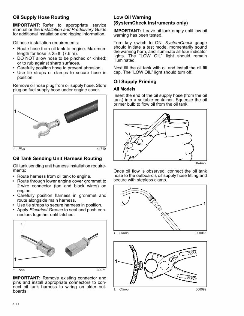
1.8 Gallon TankPlace rods into mounting bracket and securewith lag screws.
Place oil tank onto mounting bracket. If cover isnot pre-assembled, route oil supply hose andharness through the cover and position cover onthe oil tank. Attach spring-loaded rods to coveras shown.
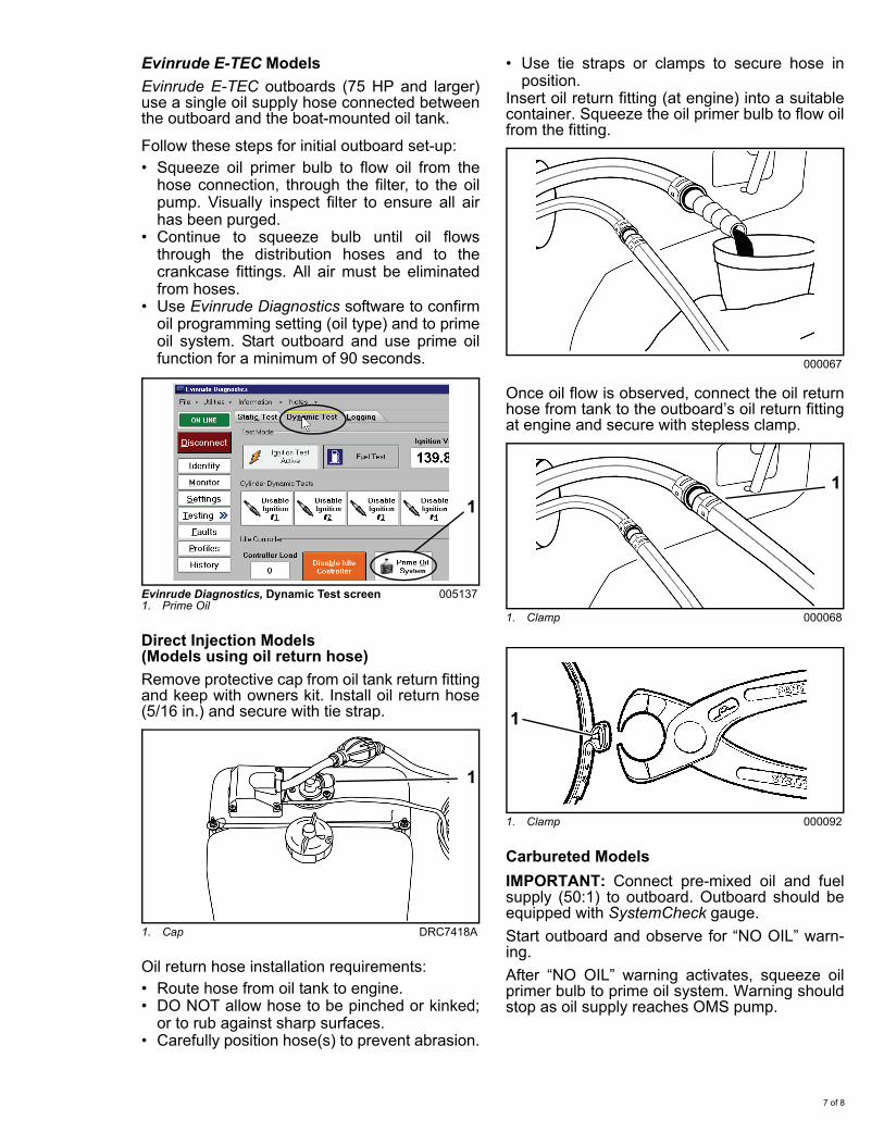
3 Gallon (11.4 L) TankPlace rods into mounting bracket and secure lagscrews.
Place oil tank onto mounting bracket. Assemblecrossbar onto rods, install flat washers andlocknuts. Tighten locknuts to secure tank.
COB5381
1. Rods2. Screws
22149A
1. Rods 48704
1
2
1 1
1. Rods2. Screws
22241B
1. Crossbar DRC7418
2
1
1
5 of 8
Oil Supply Hose RoutingIMPORTANT: Refer to appropriate servicemanual or the Installation and Predelivery Guidefor additional installation and rigging information.
Oil hose installation requirements:• Route hose from oil tank to engine. Maximum
length for hose is 25 ft. (7.6 m).• DO NOT allow hose to be pinched or kinked;
or to rub against sharp surfaces.• Carefully position hose to prevent abrasion.• Use tie straps or clamps to secure hose in
position.
Remove oil hose plug from oil supply hose. Storeplug on fuel supply hose under engine cover.
Oil Tank Sending Unit Harness RoutingOil tank sending unit harness installation require-ments:• Route harness from oil tank to engine.• Route through lower engine cover grommet to
2-wire connector (tan and black wires) onengine.
• Carefully position harness in grommet androute alongside main harness.
• Use tie straps to secure harness in position.• Apply Electrical Grease to seal and push con-
nectors together until latched.
IMPORTANT: Remove existing connector andpins and install appropriate connectors to con-nect oil tank harness to wiring on older out-boards.
Low Oil Warning(SystemCheck instruments only)IMPORTANT: Leave oil tank empty until low oilwarning has been tested.
Turn key switch to ON. SystemCheck gaugeshould initiate a test mode, momentarily soundthe warning horn, and illuminate all four indicatorlights. The “LOW OIL” light should remainilluminated.
Next fill the oil tank with oil and install the oil fillcap. The “LOW OIL” light should turn off.
Oil Supply PrimingAll ModelsInsert the end of the oil supply hose (from the oiltank) into a suitable container. Squeeze the oilprimer bulb to flow oil from the oil tank.
Once oil flow is observed, connect the oil tankhose to the outboard’s oil supply hose fitting andsecure with stepless clamp.
1. Plug 44710
1. Seal 39971
1
1
DR4422
1. Clamp 000066
1. Clamp 000092
1
1
6 of 8
Evinrude E-TEC ModelsEvinrude E-TEC outboards (75 HP and larger)use a single oil supply hose connected betweenthe outboard and the boat-mounted oil tank.
Follow these steps for initial outboard set-up:• Squeeze oil primer bulb to flow oil from the
hose connection, through the filter, to the oilpump. Visually inspect filter to ensure all airhas been purged.
• Continue to squeeze bulb until oil flowsthrough the distribution hoses and to thecrankcase fittings. All air must be eliminatedfrom hoses.
• Use Evinrude Diagnostics software to confirmoil programming setting (oil type) and to primeoil system. Start outboard and use prime oilfunction for a minimum of 90 seconds.
Direct Injection Models(Models using oil return hose)Remove protective cap from oil tank return fittingand keep with owners kit. Install oil return hose(5/16 in.) and secure with tie strap.
Oil return hose installation requirements:• Route hose from oil tank to engine. • DO NOT allow hose to be pinched or kinked;
or to rub against sharp surfaces.• Carefully position hose(s) to prevent abrasion.
• Use tie straps or clamps to secure hose inposition.
Insert oil return fitting (at engine) into a suitablecontainer. Squeeze the oil primer bulb to flow oilfrom the fitting.
Once oil flow is observed, connect the oil returnhose from tank to the outboard’s oil return fittingat engine and secure with stepless clamp.
Carbureted ModelsIMPORTANT: Connect pre-mixed oil and fuelsupply (50:1) to outboard. Outboard should beequipped with SystemCheck gauge.Start outboard and observe for “NO OIL” warn-ing. After “NO OIL” warning activates, squeeze oilprimer bulb to prime oil system. Warning shouldstop as oil supply reaches OMS pump.
Evinrude Diagnostics, Dynamic Test screen1. Prime Oil
005137
1. Cap DRC7418A
1
1
000067
1. Clamp 000068
1. Clamp 000092
1
1
7 of 8

Oil Tank Profiles
Remote Oil Fill Kit (Optional)The remote oil fill kit (P/N 176461) provides adeck-mounted fill tube, cap, and a tank-mountedtube and nut to replace the original oil tank capassembly.
Installation Recommendations• Select a location on the deck of the boat that
is above the oil tank fill cap.• Select a deck location which allows the
required length of 1½ in. I.D. fill hose to routeas directly and as vertically as possible.
• Avoid inappropriate hose routings that coulddistort the fill tube or tank tube.
• Refer to installation instructions provided withremote oil fill kit.
A slanted area of the deck will allow water todrain away from the fill and is best suited forthe installation.
Additional Items Required• 1½ in. I.D. fill hose cut to required length. Fill
hose (P/N 123956) is available in 25 ft. (7.6m) lengths.
• Two corrosion resistant 2 in. (50 mm) hoseclamps.
7.3"
9"
7.8"
2.9"
10.2"
1.8 Gallon
11.8"
9.2"
8"
3.15"
3 Gallon
11"
004949
DRC8123
8 of 8