Installation Instructions - Regal Ideas Inc...FRAMELESS GLASS RAILING SYSTEM ® Installation...
18
FRAMELESS GLASS RAILING SYSTEM ® Installation Instructions regalideas.com NAHB Best of IBS Winner for “Most Innovative Building Product” -International Builders Show
Transcript of Installation Instructions - Regal Ideas Inc...FRAMELESS GLASS RAILING SYSTEM ® Installation...

FRAMELESS GLASS RAILING SYSTEM
®
Installation Instructions
regalideas.com
NAHB Best of IBS Winner for “Most Innovative Building Product”
-International Builders Show

FRAMELESS GLASS RAILING SYSTEM
® Frameless Glass Railing Installation Instructions
regalideas.com
1
BEFORE YOU BEGIN 2PLANNING 3-4REQUIRED TOOLS 4
INSTALLATION (DECK OR FLAT SURFACE) 5GLASS MOUNTS 6
LED CONNECTION 6
TEMPERED GLASS PANELS 7
GATE 8-9
BRACING CLIPS 10-11
INSTALLATION ON STAIRS 13STAIR GLASS MOUNTS 14
TEMPERED STAIR GLASS 15SECONDARY HANDRAIL ON STAIRS 16-17
V1.2

regalideas.com
CrystalRail Frameless Glass Railing Information and Guidelines:
1. The following guide will illustrate how the various components of the CrystalRail Frameless Glass System work together.
2. The system is made of 5 major components: a) 10mm Tempered Glass Panels b) Glass Mounts w/LED c) LED Controller d) Clips and Accessories e) Stair Railing 3. The 10mm Tempered Glass panels are Low in iron content,
which produces a crystal clear glass panel. Regal Ideas will not sell the Crystal Rail components without the Regal Ideas glass panels included. Using any other glass panels that are not purchased from Regal ideas Inc. will VOID all warranties and testing approvals.
4. Codes may vary by area. We recommend that you check with your local Building Code Department for guidelines and limitations before installation.
5. LED lighting: Each base includes a 3Watt LED bulb. To make the LED system operate, you will need a Control Unit (CRLC) and Connector Cables (CRDT) (sold separately). The LED system is “plug and play”, meaning no hardwiring or splicing of wires is required.
6. Bracing Clips and Supports: Above grade applications and openings require the use of glass Bracing Clips between panels and on ends/openings.
2
Surfaces and Structures• When installing glass mounts, bracing clips
and other components into a wall, floor or fixed object, ensure you have a solid structure for the fasteners/anchors to bite into and help distribute the loads that get applied to the system when in use.
• Mounting surfaces for the glass mounts, bracing clips and components must be flat, solid, free from cracks,debris, and compliant with local building codes.
• Fasteners• Fastener type and length will vary depending on
the surface and material you are mounting into. • This manual will guide you on the recommended
fasteners and mounting plates to use.• Remember to always check with your local
building departments to ensure you are using the correct fasteners for your area.
•
Safety First• Whenever you work with glass, you need to wear safety glasses.• You should always wear safety gloves when you work with tempered glass. Make sure that the gloves are
strong enough to protect your hands in case of breakages.• CrystalRail Tempered Glass Panels are 10mm thick and can be heavy for a one person lift. To prevent person-
al injury and avoid glass damages, two persons are suggested to handle each glass panel during installation. Use of the Vacuum Cup (model: CVC) tool will make handling and installation of the tempered glass panels easier.
• DO NOT attempt to use a glass cutting tool to cut tempered glass. Attempting to cut tempered glass will result in the panels breaking and/or shattering.
• Tempered glass is strong, durable and safe when handled correctly. While the glass is strong, the corners are the most vulnerable points and need to be protected as much as possible. If you don’t pay attention when handling the glass, there’s a danger of catching the corner on a snagging point and it will cause the glass to shatter.
• With tempered glass, you need to be very careful how you stand the glass. Don’t stand a sheet of tempered glass on cement, tile or composites, where it can easily slip and shatter.
• DO NOT cut, splice or direct wire your LED system. This will VOID the warranty.
FRAMELESS GLASS RAILING SYSTEM
® Frameless Glass Railing Installation Instructions
BEFORE YOU BEGIN: CrystalRail Frameless Glass Railing System has specific requirements and certain preparations are needed before installation. This system may not be suitable for certain existing deck framing configurations and may require additional decking support prior to installation of the Crystal Rail system. Please ensure you read and follow the instructions outlined in this manual. For suitable applications, check with your local Regal ideas Dealer and ensure to refer to your local Building Code for guidelines and limitations before you begin installation.
7. Handrail requirements: A continuous stair railing is required to be installed when using the Crystal-Rail system on the stairs (Page 13). ADA/Second-ary rail may also be used on the horizontal portion of the CrystalRail if desired.
V1.2

regalideas.com
3
FRAMELESS GLASS RAILING SYSTEM
® Frameless Glass Railing Installation Instructions
Section 1 | Planning
General sequence of Crystal Rail installation1. Install mounting brackets on deck and stairs ( begin with openings for gates or stairs)2. Connect wiring and check that all LED lights are functioning properly3. Install glass panels4. Install stair glass panels5. Install gates6. Install all bracing clips7. Install top and bottom support posts8. Install handrail assembly
Planning Before beginning installation, it is critical to carefully plan the layout of the installation. It is strongly recommended to begin the layout and installation at openings for gates or stairs as this portion requires precise positioning of components and glass panels for proper assembly. The following points must be taken into consideration when measuring and planning your layout.1. Mounting brackets (CRH) generally can be installed
a minimum of 4”, to maximum of 14”, in from edge of glass to center of mounting bracket.
2. Gap between glass and wall must be a minimum of 1.5” and no more than 2.5” to allow for installation of wall bracing clip (CRBW). If wall bracing clip cannot be utilized, installing end bracing clip (CRBE) with end support post (CRSP) must be used as an alternative.
3. Gap between glass panels must be at least 1.25” to
allow for installation of bracing clip and no more than 3.75” to meet building code requirements.
4. When installing support posts at end panels, position mounting bracket (CRH) in at least 7” from edge of glass to center of mounting bracket, to allow clearance for installation of support post.
5. Corner sections of glass must be installed with an offset
of at least 0.5” to allow for installation of bracing clip and gap must be less than 4” to meet building code requirements.
6. End pieces of deck glass at openings for stairs must extend exactly 5/8” past where stair glass intersects with deck glass to ensure proper alignment of top and bottom support posts when installing handrail for stairs.
7. Standard glass panels are utilized for Crystal rail gates, typically 36” or 42” wide panels. Openings for gates must be at least 3” larger and no more than 4” larger than glass panel used for gate. NOTE: Maximum glass size for use as gate is 42” width.
Wall Tempered Glass Panel Tempered Glass Panel
CRBE
0.5”Openings between glass must be less than 4”
0.5”
5/8”
Gap can be 1.5”-2”on the hinge side
Gap must be 1.5”on the latch side
CRSP
CRH
CRBACRBW
Minimum 1.5”Maximum 2.5”
Minimum 4”Maximum 14” (from edge of glass to center of mounting bracket)
Minimum 1.25”Maximum 3.75”
Minimum 4”Maximum 14”
Minimum 7”(when installing support post at end panel/opening)
1
2 3
4
5
6
7
Diagram A
Diagram B
V1.2
regalideas.com
4
FRAMELESS GLASS RAILING SYSTEM
® Frameless Glass Railing Installation Instructions
Section 1 | Planning
Planning Continued...
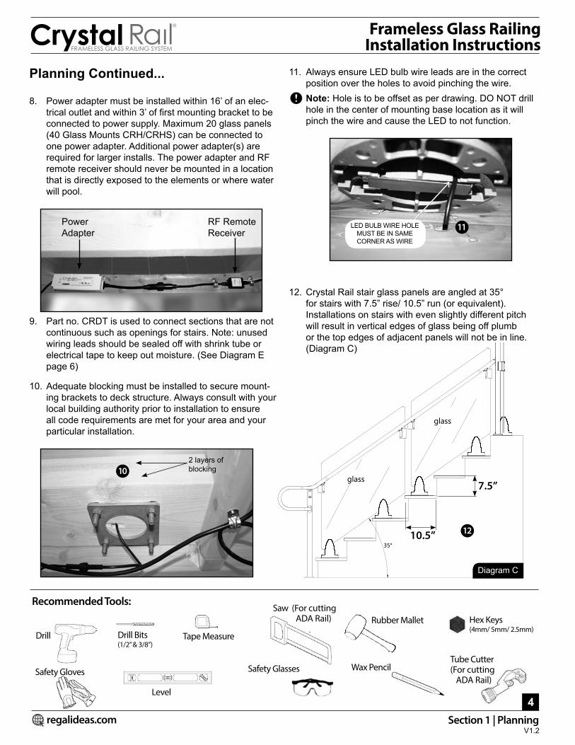
8. Power adapter must be installed within 16’ of an elec-trical outlet and within 3’ of first mounting bracket to be connected to power supply. Maximum 20 glass panels (40 Glass Mounts CRH/CRHS) can be connected to one power adapter. Additional power adapter(s) are required for larger installs. The power adapter and RF remote receiver should never be mounted in a location that is directly exposed to the elements or where water will pool.
9. Part no. CRDT is used to connect sections that are not continuous such as openings for stairs. Note: unused wiring leads should be sealed off with shrink tube or electrical tape to keep out moisture. (See Diagram E page 6)
10. Adequate blocking must be installed to secure mount-ing brackets to deck structure. Always consult with your local building authority prior to installation to ensure all code requirements are met for your area and your particular installation.
11. Always ensure LED bulb wire leads are in the correct position over the holes to avoid pinching the wire.
Note: Hole is to be offset as per drawing. DO NOT drill hole in the center of mounting base location as it will pinch the wire and cause the LED to not function.
12. Crystal Rail stair glass panels are angled at 35° for stairs with 7.5” rise/ 10.5” run (or equivalent). Installations on stairs with even slightly different pitch will result in vertical edges of glass being off plumb or the top edges of adjacent panels will not be in line. (Diagram C)
Recommended Tools:
Drill Drill Bits (1/2” & 3/8”)
Level
Saw (For cutting ADA Rail)
Safety GlassesSafety Gloves Wax Pencil
Tape Measure
About ADA armrest in glass railing test
glass
glass
35°
11
12
2 layers of blocking10
PowerAdapter
RF RemoteReceiver
7.5”
10.5”
Hex Keys (4mm/ 5mm/ 2.5mm)
Tube Cutter(For cutting ADA Rail)
Rubber Mallet
LED BULB WIRE HOLE MUST BE IN SAME CORNER AS WIRE
Diagram C
V1.2

CRH Horizontal Glass Mount with LED• To hold CrystalRail Low-Iron
tempered glass panels (CRG)• c/w white LED light inside mount
CRLCLED Controller & Remote• For use with Crystal Rail glass
mounts• Max 40 glass mounts per con-
troller
CRDTDouble-T Splitter Connection Cord• 78” (2 meter) cord• Connects power to LED’s• One required for each glass
section (per 2 mounts)
CRG24-60CrystalRail Low-Iron Tempered Glass• 10mm thickness
CVCVacuum Cup• Vacuum tool for easier moving
and handling of 3/8” (10mm) glass panels (2 required)
CRBWAdjustable Wall Bracing Clip• To secure 10mm CrystalRail
Tempered Glass panel to Wall.• Made from 100% aluminum.
CRBAAdjustable Angle and Line Clip• Secures two CrystalRail Tem-
pered Glass panels together. Used in-line or on corners.
• Made from 100% aluminum.
CRSPEnd Bracing Support • Provides support to
CrystalRail Tempered Glass panel that is open on one side. (i.e. stair opening).
CRBC Base Plate Cover for Support Post• Wraps post base to hide fasten-
ers and provide a more finished appearance.
CRBE End Bracing Clip• Bracing clip to connect Crystal
Rail glass panels to end support post at end section of horizontal glass.
CRGH Gate Hinge Set• Durable hinge set used to hold
the Crystal Rail Glass panel for the gate.
CRILMagnetic In-line Gate Latch • Adjustable magnetic in-line
latching system• For use in horizontal in-line gates
CRCLMagnetic Corner Gate Latch• Adjustable magnetic corner gate
latching system• For use in 90° corner gates
CRGGGlue Dispenser• Applicator for 2 part epoxy.• Used to fasten Crystal Rail brac-
ing clips to glass.
CREG Acrylic Adhesive• Used to fasten Crystal Rail
bracing clips to glass. Includes glue tube with mixer tips and 4 needle tips.
MP55” Aluminum Bolt-Through Mount-ing Plate• For undermount application.
FRAMELESS GLASS RAILING SYSTEM
® Frameless Glass Railing Installation Instructions
INSTALLATION INSTRUCTIONS (ON FLAT SURFACES)
Component Profiles:
regalideas.com
5Section 2 | Installation (Deck or Flat Surface)
1.25in - 3.75in
3-6i
n
1.25in - 3.75in
3-6i
n
3-6i
n
1.25in - 2.5in
CRSP-SA
CRBC-SA
CRBE-SA
CRBA-SA
OFF
ON
CRH-SADiagram D
V1.2

regalideas.com
6
FRAMELESS GLASS RAILING SYSTEM
® Frameless Glass Railing Installation Instructions
Installing CRH Mounting bracketsOnce installation layout has been determined and adequate blocking has been installed, you are now ready to install the CRH Mounting Brackets.
1. Pre-drill holes for securing mounting brackets using 3/8” drill bit and ensure you drill all the way through the block-ing for the bolts to pass through.
Note: ensure holes are drilled plumb for mounting plates to fit on bolts on underside of blocking.
2. Drill ½” holes for wiring of the LED lighting. Make sure ½” hole for wiring is NOT drilled directly in the center, it must be offset as per template.
3. Feed the lighting wire into the hole while positioning the mounting bracket in place.
Caution: Always check that you DO NOT pinch the wire between deck and bracket.
4. Secure mounting brackets to deck with appropriate length bolts depending on your decking material (5”-6” bolt length).
5. Use the Mounting Plate (MP5) on the underside of the blocking before adding nuts to bolts.
Note: Make sure to install base covers on all mounting bracket before installing glass.
Installing LED Wiring.
1. After mounting brackets have been installed, secure the power adapter to frame of deck and connect the RF re-ceiver to adapter. (Refer to point 8 of “Planning” section).
Note: Do not connect adapter to power supply until installation of all wiring is complete. Be careful not to dislodge O-rings from connector ends during installation. This will compromise water tightness.
2. Attach first LED connector cord (CRDT) to the RF receiver plug and attach the two male leads of the first connector cord to the female leads of the LED bulbs of first 2 brack-ets (each connector cord connects 2 bulbs for one section of glass). See above Diagram E.
Section 2 | Installation (Deck or Flat Surface)
Connection Detail:
CrystalRail Tempered Glass
CRLC
CRDTCRDT CRDTCRH
CRBA CRBA
3.75”
1.375”
0.5”
1/2”
3/8”
3.75”
1
2
3
4 5
2 layers of blocking
1
14 2 3 33
3 33
3 3
5
Diagram E
V1.2

regalideas.com
7
FRAMELESS GLASS RAILING SYSTEM
® Frameless Glass Railing Installation Instructions
Section 2 | Installation (Deck or Flat Surface)
3. Complete installation of wiring to remaining sections by connecting each connector cord to the previous and connecting female leads of bulbs to male leads of the connector cords. (See Diagram E)
4. After all sections have been connected, plug in the adapt-er to power supply, insert battery (included) in remote controller and press both on and off buttons at the same time to initialize the remote.
5. Activate the lighting to check that all lights are func-tioning before installing glass panels. Disconnect from power supply before continuing the installation. Secure wiring to deck structure using 1/4” cable clips (use 3/8” for power adapter cord) As shown on page 6.
Installing Tempered Glass PanelsPlease read tempered glass handling and safety instructions on page 2 before handling tempered glass panels.Tip: Use CVC Vacuum Cup to lift tempered glass panels into position.1. Ensure base covers are installed before installing glass.2. Begin with all four set screws of each mounting bracket
exactly flush with inside surface of mounting brackets.3. Insert the rubber gasket/plates with the rubber side
facing towards the inside of the bracket, and the aluminum side against the aluminum base.
4. Insert tempered glass panel into CRH Mounting Brackets. Ensure glass is placed in between both rubber gasket/plates.
Tip: If plate is difficult to fully install, spray some warm water or window cleaner onto the rubber gasket, and gently rock the glass while pushing the plate into place.
5. Adjust the glass vertically (if necessary) by turning the 4mm hex socket bolts located at the base of each glass mount (counter clockwise). Bolt may require several turns before the glass begins to adjust.
IMPORTANT: Vertical adjusting MUST be done before tightening set screws on side of brackets to secure glass in place.6. Once all vertical adjustments have been made, secure
the glass by tightening the set screws located on each side of the glass mounts (2 per side). Begin by tighten-ing each of the upper set screws on each bracket two full turns.
7. Next, tighten each of the lower set screws on each bracket one and a half turns. DO NOT over tighten. Glass can be plumbed by backing off one of the upper set screws and tightening the opposite upper set screw the same amount.
8. Glass is now secure and plastic covers can be installed over the adjustment screws.
4
4
1
62
7
8
2
5
3
Connects to CRDTConnector Cord
Glass Mounting Bracket (CRH) shown with glass installed.
4
2
V1.2

regalideas.com
8
FRAMELESS GLASS RAILING SYSTEM
® Frameless Glass Railing Installation Instructions
Section 2 | Installation (Deck or Flat Surface)
Installing Gate Hinge Assembly (CRGH)IMPORTANT: Gap on the latch side of the gate panel is a fixed measurement of 1.5”. Make sure hinge assembly is installed to leave the correct gap on the latch side.1. Begin by removing all plastic covers from hinge assembly
and put aside.2. Mount lower bracket receiver to deck at a distance of 3”
from edge of glass panel end.(Diagram F)3. Slide upper bracket onto end of the glass panel, and
flush with the edge of the glass. 4. Beginning with the set screws flush with the set screw
holes, secure bracket to glass by turning each of the 8 set screws (4 per side) exactly two full turns.
5. Slide the lower gate panel pin bracket into position on gate panel and secure by tightening all 8 set screws two full turns. Gap between end panel and gate panel is determined by the positioning of the upper and lower gate panel brackets. Brackets can be set in a minimum of 0.5” for 2.5” gap or up to 1.5” set in from edge of glass for 1.5” gap.
6. Position upper gate panel pin bracket onto glass with same inset distance as lower bracket and secure by tightening the 8 set screws two full turns from flush position.
7. Use a piece of wood to hold up the latch side of gate panel up 2” to keep level, then lift glass into position with lower pin into pin receiver bracket.
8. Insert pin of top hinge connector into top gate panel pin receiver. Then secure top hinge connector to end panel bracket with by firmly tightening the four 5mm set screws (Make sure lock washers are installed).
9. If deck is uneven and gate panel requires leveling, back off the set screws on the bottom gate panel pin brack-et, adjust and hold the glass in level position until set screws are tightened.
10. Install covers back on all re-tightened brackets. Hinge assembly installation is now complete.
31 1
1 1
1
1
6
8
5
2
3
6
8
5
7
CRIL
4 4
4
5
6
8
4
Front/Back Covers
1
7
10/
3
Hinge
1.5”-2.5” 0.5”-1.5”
Lower Bracket Receiver
min 7”
3”Diagram F
2
V1.2
Gate assembly shown above. CRSP post is required at ends of ALL openings. (See page 10 for details)

regalideas.com
FRAMELESS GLASS RAILING SYSTEM
® Frameless Glass Railing Installation Instructions
Installing Corner Gate Latch (CRCL)
IMPORTANT: CRH (Glass Mounting Bracket) must be set back 7” minimum from the edge of the glass to the outside of the bracket to give enough clearance for gate to swing open. (Diagram F)1. Gap between end panel and edge of gate panel must be
exactly 1.5”.2. End panel glass must extend 0.75” past outside of gate
panel glass to keep gate parallel with edge of deck3. Ensure gate panel and end panel glass are leveled and
secured before installing latch. 4. Fasten the male half of the gate latch to end panel at
desired height. 5. Position the latch over the glass panel with the white
spacers up against edge of glass. 6. Firmly tighten the two 4mm set screws to secure. 7. Slide the female half of latch onto gate panel glass at
same height as male half. 8. With rubberized plate between set screws and glass
with the rubber side against glass, tighten the two 4mm set screws exactly 1 full turn past the flush position. Latch assemble is now complete.
Installing In-Line Gate Latch (CRIL)
IMPORTANT: Gap between end panel and edge of gate panel must be 1.5” exactly.1. Ensure gate panel and end panel glass are leveled and
secured before installing latch. 2. Fasten the male half of the gate latch to end panel at
desired height. 3. Position the latch over the glass panel with the white
spacers up against edge of glass. 4. Firmly tighten the two 4mm set screws to secure. 5. Slide the female half of latch onto gate panel glass at
some height as male half. 6. With rubberized plate between set screws and glass
with the rubber side against glass.7. Tighten the two 4mm set screws exactly 1 full turn past
the flush position. Latch assemble is now complete.
Section 2 | Installation (Deck or Flat Surface)
1.5” 0.75”
1
4
2
5
7
8
8
66
Front
Back
1
2 5
6
3
7
7
4
4
9
Rubber side facing glass
1.5”
V1.2
Gate opens this way
Rubberized Plate
Screw
MaleFemale

IMPORTANT: All openings in a CrystalRail system must have support posts (CRSP) installed on the open side of the glass panels. See below various installation options:
Installing Support Post (CRSP w/CRBE)*For use at end panels of deck glassNote: When end panel bracing clip is being used at an opening where a gate is to be installed, the clip must be installed 3” down from top of glass to allow for installation of the gate hardware.1. With set screws backed off, slide the CRBE clip over the
end panel. 2. Slide CRSP into flanges on the end bracing clip. 3. Level post and secure to deck using appropriate
approved fasteners and proper under-blocking. Reference Regal Post Fastening detail found at: regalideas.com/resources/downloads4. Ensuring glass is plumb, use two ¾” screws per side to
secure post to clip.5. Position set screw plate between the set screws and the
glass.6. Tighten the two set screws (2.5mm) firmly. Install
plastic covers over the top and bottom end of the clip. Installation is complete.
Note: CRBE End Bracing Clip is designed to ensure the support post is a minimum of 1” away from deck glass to allow clearance for gate hardware. Post can be mounted up to 1.5” from glass if required to ensure opening between post and edge of stair glass is less than 4” (code requirement).
Installing Support Post (CRSP)*At an opening, when the deck glass is in line with stair glass.1. Slide a Wall Bracing Clip (CRBW) onto the end panel
of glass. Position and secure post so that the post is centered with the line of the stair & deck glass. If post base is close to edge of deck, use the holes located in the middle of the base rather than outside corner hole.
2. Attach the bracing clip to the support post with four self-drilling screws.
3. Secure the wall bracing clip to the glass with acrylic adhesive. (See Diagram G, page 12)
Note: If a gate latch is being used at the end panel, make sure the post is positioned a minimum of 1.5” away from edge of glass and that the wall bracing clip is installed at a height not to interfere with the gate latch.4. Make sure the gaps on either side of the post to the deck
glass and stair glass are less than 4” (code requirement)
regalideas.com
10Section 2 | Installation (Deck or Flat Surface)
FRAMELESS GLASS RAILING SYSTEM
® Frameless Glass Railing Installation Instructions
Top View
CRSP
CRBE
Post Base
12
4
4
3
12
5
6
6
V1.2
If post base is close to edge of deck, use the holes located in the middle of the base rather than outside corner holes.

regalideas.com
11
FRAMELESS GLASS RAILING SYSTEM
® Frameless Glass Railing Installation Instructions
Installing Adjustable Clip (CRBA)*For use between 2 glass panels1. Slide clips into position on glass. Make sure the holes for the glue cavity are facing up.2. Space between glass panes should be minimum
1.25” to 3.75” maximum. If space between glass panels is larger than 4”, it will not be code compliant. (See Diagram D, page 5)
3. Clips to be installed 3” to 6” from top of glass panel. (See Diagram D, page 5)
4. Secure brackets in place using the CrystalRail Acrylic Adhesive (See instructions page 12)
Installing Adjustable Clip (CRBW)*For securing glass panel to wall1. Slide clips into position on glass. Make sure the holes
for the glue cavity are facing up. 2. Space between glass panes should be minimum 1.25”
to 2.5” maximum. If space between glass panels is larger than 4”, it will not be code compliant.
3. Clips to be installed 3” to 6” from top of glass panel. (See drawing, page 5)
4. Use appropriate fasteners to mount bracket into wall or post.
5. Secure brackets in place using the CrystalRail Acrylic Adhesive (See instructions page 12)
Installing Base Plate Cover (CRBC)1. Position the two piece base plate cover around base of
post and push to lock in place. TIP: Apply dab of silicone on heads of post mounting bolts before installing base plate covers to secure in place.
Section 2 | Installation (Deck or Flat Surface)
1
1
1
1.25” - 3.75”
3”-6”
3”-6”
2
3
3
4
4
V1.2

regalideas.com
12
FRAMELESS GLASS RAILING SYSTEM
® Frameless Glass Railing Installation Instructions
GLUE DISPENSER AND ADHESIVEWarning!: Please read and carefully follow ALL safety precautions as noted on the product packaging before using the Acrylic adhesive.
GLUE DISPENSER FOR ACRYLIC ADHESIVE (CRGG) 1. Press and hold metal lever while inserting plunger to
start position.2. With locking mechanism in up position, load glue car-
tridge in gun, then secure in place with locking mecha-nism.
3. Remove cap from glue cartridge by rotating it 90 degrees counter clockwise and pull cap from cartridge.
4. Attach nozzle and turn 90 degrees clockwise to secure in place.
5. Firmly press dispensing needle onto nozzle.6. Insert needle into filling hole and dispense adhesive until
glue reaches overflow hole at top of clip.7. Disengage plunger after usage and remove nozzle and
replace cap on glue cartridge.Note: Nozzles and dispensing needles cannot be reused. Glue will begin to set within a few minutes of non usage. For this reason, it is suggested that all parts requiring glue be installed first and then glue applied at the same time.
2 PART ACRYLIC ADHESIVE Read directions and test a small area before use.
SET TIME: 5 minutes to apply and position. HANDLING TIME: 5 minutes undisturbed.CURE TIME: 24 hours for load bearing weight. Application in cooler temperatures and moist conditions may cause longer cure times. CURED COLOUR: Semi-clearTEMP RANGE: Bond withstands -50°C to 150°C. STORAGE: Store in a cool, dry place.CLEAN UP: Remove excess glue immediately from project surfaces with dry cloth, Scrape off any excess cured adhesive.
FIRST AID TREATMENT: If swallowed, call a Poison Control Centre or doctor immediately. Do not induce vomiting. If in eyes or on skin, rinse well with water for min 15 minutes. If breathed in, move person into fresh air.
Contains: Methyl methacrylate (80-62-6), Methacrylic acid (79-41-4), Benzoyl Peroxide (94-36-0)Diisononyl phthalate (28553-12-0), High molecular polymer.
CRH
CRBWCRBA
CRBA
Section 2 | Installation (Deck or Flat Surface)
Diagram G
CONTENTS MAY BE HARMFUL. MAY IRRITATE EYES AND SKIN. Do not mix with other chemicals. Do not Swallow. Do not get in eyes or on skin or clothing. KEEP OUT OF REACH OF CHILDREN. WEAR SAFETY GLASSES AND CHEMICAL RESISTANT GLOVES. Do not breathe fumes. Use in a well-ventilated area. Wash hands thoroughly after handling. Do not eat, drink or smoke when using this product.
V1.2

FRAMELESS GLASS RAILING SYSTEM
® Frameless Glass Railing Stair Installation Instructions
Component Profiles:
regalideas.com
13Section 3 | Installation on Stairs
CRHS Stair Glass Mount with LED• To hold CrytalRail Low-Iron
tempered glass panels on stairs (CRSG)
• c/w white LED light inside mount
CRSG03-05CrystalRail Low-Iron Tempered Stair Glass (10mm thickness)
HBG10mm Glass Bracket• To attach hand/stair rail to Crystal-
Rail 10mm glass• WCS-50-SA screws required to
attach handrail to HBG bracket.
HGCAdhesive Mounted Handrail Bracket• Used with CrystalRail stair glass
where handrail brackets are required to be placed 4ft or less apart.
HSFHandrail Sleeve Fitting• Sleeve fitting attaches handrail
to end support post when using ADA handrail with CrystalRail stair glass.
• WCS-50-SA screws required.
CRSPEnd Bracing Support • Provides support to
CrystalRail Tempered Glass panel that is open on one side. (i.e. stair opening).
CRBC Base Plate Cover for Support Post• Wraps post base to hide fasten-
ers and provide a more finished appearance.
MP55” Bolt-Through Mounting Plate• For undermount application.
HR088ft Hand/Stair Rail• Wraps post base to hide fasten-
ers and provide a more finished appearance.
HCR 90° Corner/Return Rail Section• To accommodate 90°corner or
ground return.
HW9090° Wall Return• To accommodate 90° return into
wall or post.
HLRHandrail Loop Return • 180° return to finish handrail
system.
HE3535° Elbow • Connects 180° handrail return to
hand/stair rail on stair applica-tions.
HSCRail Splice and Cap• 6” splice to connect sections of
hand/stair rail. • Requires four (4) WCS-50-SA.
HECEnd Rail Cap• End cap for rails.
HWCHandrail Wall/Post Return Connector• Used to cap the end of the hand
rail tube against a wall, post or ground return.
About ADA armrest in glass railing test
glass
glass
35°
12”
Crystal Rail Stair & ADA HandrailConnection Detail:
CRSP
HE35
HBG
HBG
HCRHSC
CRBC
CRHS
CRBE
HSF
Diagram H
About ADA armrest in glass railing test
glass
glass
35°
Glass 1”-1.5” in from tread nosing
7/8”
V1.2

regalideas.com
14
FRAMELESS GLASS RAILING SYSTEM
® Frameless Glass Railing Stair Installation Instructions
Installing Stair Mounting brackets (CRHS)
1. Decide the layout of the stair glass panels to determine the treads on which to place the mounting
brackets. Brackets must be installed on the treads closest to each end of glass panel.
2. To ensure proper alignment of all components when installing support posts and ADA, position the CRHS stair mounting brackets so that the line of the stair glass intersects with deck glass as described in point #6 of the Planning Layout section.
3. Drill the 4 mounting holes for 3/8” bolts and 1/2” hole for LED wiring. Sweep or vacuum all dust and files immediately after drilling is complete to avoid scratch-ing components while installing.
4. Position mounting bracket in place while feeding the LED wire through the stair tread, taking care that wire is not pinched when mount is in place.
5. Make sure the mounting bracket is facing in the correct direction so that the adjustment plate is following the same angle as the stairs.
6. Insert 4 mounting bolts and position mounting plate (MP5) onto bolts underneath the stair tread.
7. Tighten nuts onto bolts to secure. Make sure LED wire is through center mounting plate hole before tightening.
8. Connect LED bulb leads to the connector cord.
9. Use UV stabilized cable ties to secure wiring if using metal stair stringers. Use 1/4” cable clips for wood stringers.
Note: Make sure to install base covers on all mounting bracket before installing glass.
Section 3 | Installation on Stairs
About ADA armrest in glass railing test
glass
glass
35°
3/8”
1/2”3
1
3
4
End glass panel must extend exactly 5/8” past inside edge of stair glass for top and bottom support post to align.
Diagram I
Diagram J
Glass 1”-1.5” in from tread nosing
5/8”
7/8”
About ADA armrest in glass railing test
glass
glass
35°11” Above tread nose
5
6 6
66
7
V1.2

regalideas.com
15
FRAMELESS GLASS RAILING SYSTEM
® Frameless Glass Railing Stair Installation Instructions
Installing Tempered Glass Panels on StairsPlease read tempered glass handling and safety instructions on page 2 before handling tempered glass panels.
Tip: Use CVC Vacuum Cup to lift tempered glass panels into position.
1. Ensure base covers are installed before installing glass.2. Begin with all four set screws of each mounting bracket
exactly flush with inside surface of mounting brackets. Set screws for the stair mounting brackets are in the top hole and the third from top hole, on the side of the brackets.
3. Insert the rubber gasket/plates with the rubber side facing towards the inside of the bracket, and the aluminum side against the aluminum base.
4. Position glass panel into mounting brackets. (2 persons are required to complete installation).
5. Vertical edges of glass should be 1”-1.5” away from stair tread nose at the upper and lower ends of the glass.
6. Space between glass panels must be less than 4” as required by building code.
7. With glass still being held in place by person one, secure the glass in place by turning the set screws as noted below. First, turn inside and outside upper set screws exactly 3 turns on each bracket.
8. Second, turn inside and outside lower set screws ex-actly 2 turns on each bracket. Do NOT over tighten set screws.
9. Glass is now secure and plastic covers can be installed over adjustment screws.
NOTE: Stair glass must also be supported with ADA hand-rail and top and bottom support posts.
Section 3 | Installation on Stairs
1
72
2
89
2
3
Connects to CRDTConnector Cord
Glass Mounting Bracket (CRH) shown with glass installed.
4 About ADA armrest in glass railing test
glass
glass
35°
5
6
Diagram K About ADA armrest in glass railing test
glass
glass
35°5
Glass 1”-1.5” in from tread nosing
7/8”
V1.2

About ADA armrest in glass railing test
glass
glass
35°
About ADA armrest in glass railing test
glass
glass
35°
regalideas.com
16
FRAMELESS GLASS RAILING SYSTEM
® Frameless Glass Railing Stair Installation Instructions
INSTALLING SECONDARY HANDRAIL NOTE: Stair glass is designed to be 1” above from tread nosing to give overall height of 42” measured vertically from stair tread nosing to top edge of glass. Measurements in this section are assuming stair glass is installed to these parameters. All “height” measurements are measured vertically from stair tread nose.
Installing Handrail Support Post (CRSP) at Bottom of Stairs1. Install support post centered with the line of the stair
glass at ground or landing using appropriate approved fasteners for substrate
2. Distance of post from bottom tread will depend on the handrail configuration chosen.
3. Position the two piece base plate cover around base of post and push to lock in place.
A) Install Handrail Brackets on Glass Edge (HBG) Below measurements are based on a typical 34” hand-
rail height.
1. Install the HBG bracket on the lower side of glass: 9” down from top of glass
2. Install the HBG bracket on the upper side of glass: 11” down from top of glass.
3. To install the HBG, position the handrail connector portion of the bracket into the clamping portion. Make sure the setscrews are backed off flush with inside sur-face of the clamping part of the bracket.
4. Slide bracket into position onto the glass. If bracket is
tight to fit on glass, hold the bracket against the glass at a slight angle and gently tap the bracket to start it onto the glass (taking care not to impact the glass).
5. Firmly tighten the two 2.5mm hex socket set screws to secure in place.
Section 3 | Installation on Stairs
Line up center of Handrail Support Post (CRSP) to cen-ter of stair glass.
3
5
1
2
5
4
Diagram L
Diagram M
9”
11”
About ADA armrest in glass railing test
glass
glass
35°!1” Above tread nose
1
2
V1.2

regalideas.com
17
FRAMELESS GLASS RAILING SYSTEM
® Frameless Glass Railing Stair Installation Instructions
B) Install Handrail Sleeve Fitting (HSF)1. To determine the positioning of the sleeve fitting on the
top support post, temporarily connect a 90 degree cor-ner to a handrail section.
2. Slide the sleeve fitting onto the 90 corner. Position (do not fasten) handrail onto HBG brackets with pivoting tabs at the same angle as glass.
3. With the 90 degree elbow sitting horizontally and point-ing away from the stairs, mark the position of the HSF on the support post and mark the portion of the elbow to be cut away. Elbow should extend minimum 1” past the support post.
4. Cap the open end with the HEC cap.5. Fasten to the support post using three ¾” screws.
C) ADA/Secondary handrail configuration ADA/Secondary handrail instructions can be downloaded at: http://regalideas.com/products/ada_secondary_handrail/
D) Installing Face Mount Handrail Bracket (HGC)
1. Install HGC after handrail has been secured to glass using the edge mounted brackets.
2. Remove the adhesive backing and position the bracket on the glass.
3. Connect the bracket to the handrail using two ¾” self-drilling screws.
4. Secure the bracket to glass by filling the cavity with acrylic adhesive.
5. Remove the adhesive backing from the finishing plate and apply to outside face of glass to complete installation.
Section 3 | Installation on Stairs
1
2
4
35Minimum 1”
CRSPHEC
HCR
HSC
HSF
C) ADA/Secondary handrail configuration
Note: HGC is only required on CRSG5 (5-step stair glass) applications where code requires brackets to be less than 48” apart.
ADA/Secondary handrail instructions can be downloaded at: http://regalideas.com/products/ada_secondary_handrail/
2
3
4
5
3
V1.2