INSTALLATION INSTRUCTIONS MOONRING 1.5 MOONRING 3
14
A 1035 22nd Avenue, Unit 1 n Oakland, CA 94606 P 510.489.2530 E [email protected] W alwusa.com INSTALLATION INSTRUCTIONS MOONRING 1.5 MOONRING 3 (Rings, Arcs, & Ellipses) MR1.5 & MR3 | Suspended, Ceiling| LED | Standard & Acoustic
Transcript of INSTALLATION INSTRUCTIONS MOONRING 1.5 MOONRING 3

A 1035 22nd Avenue, Unit 1 n Oakland, CA 94606 P 510.489.2530 E [email protected] W alwusa.com
INSTALLATION INSTRUCTIONS
MOONRING 1.5MOONRING 3
(Rings, Arcs, & Ellipses)
MR1.5 & MR3 | Suspended, Ceiling| LED | Standard & Acoustic
MR1.5/MR3 Installation Guide 2 of 14 102-000021 - IG050720
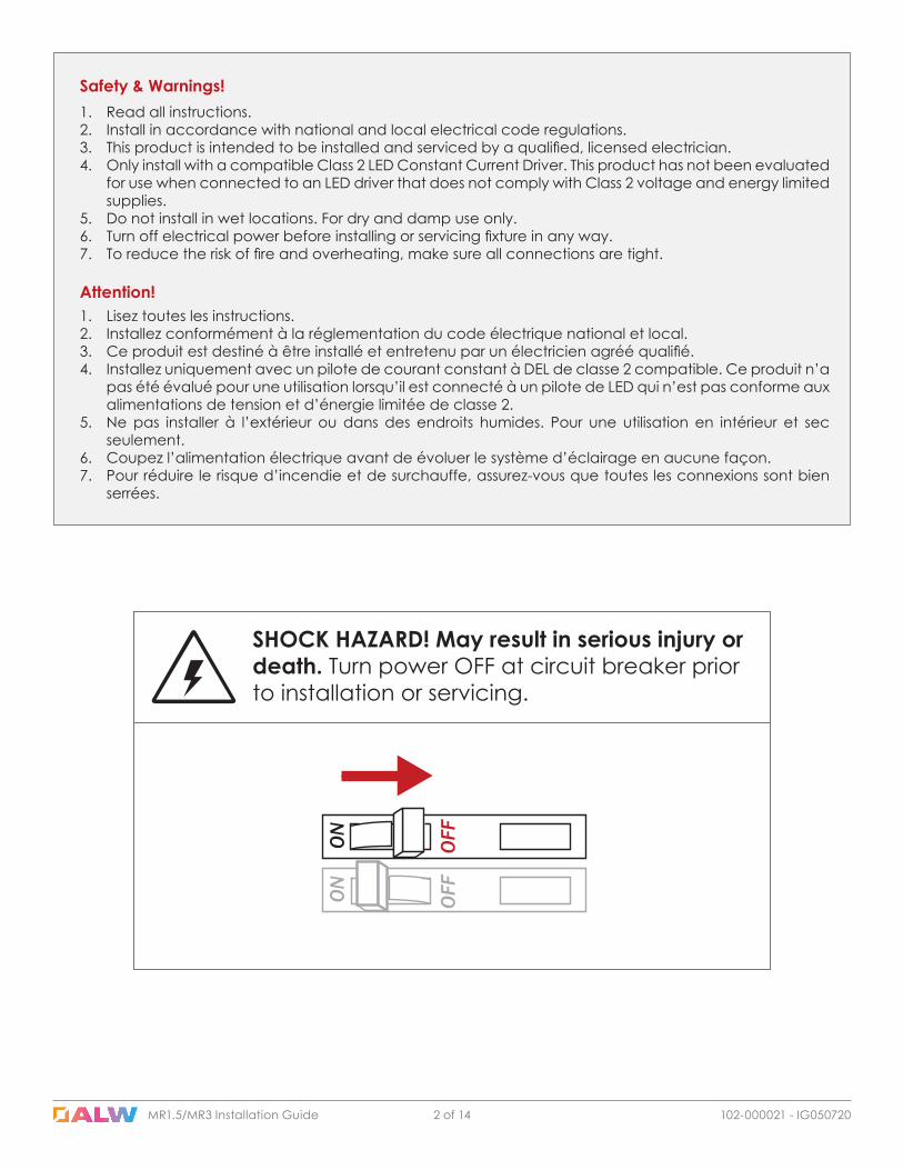
Safety & Warnings!1. Read all instructions.2. Install in accordance with national and local electrical code regulations.3. This product is intended to be installed and serviced by a qualified, licensed electrician.4. Only install with a compatible Class 2 LED Constant Current Driver. This product has not been evaluated
for use when connected to an LED driver that does not comply with Class 2 voltage and energy limited supplies.
5. Do not install in wet locations. For dry and damp use only.6. Turn off electrical power before installing or servicing fixture in any way.7. To reduce the risk of fire and overheating, make sure all connections are tight.
1. Lisez toutes les instructions.2. Installez conformément à la réglementation du code électrique national et local.3. Ce produit est destiné à être installé et entretenu par un électricien agréé qualifié.4. Installez uniquement avec un pilote de courant constant à DEL de classe 2 compatible. Ce produit n’a
pas été évalué pour une utilisation lorsqu’il est connecté à un pilote de LED qui n’est pas conforme aux alimentations de tension et d’énergie limitée de classe 2.
5. Ne pas installer à l’extérieur ou dans des endroits humides. Pour une utilisation en intérieur et sec seulement.
6. Coupez l’alimentation électrique avant de évoluer le système d’éclairage en aucune façon.7. Pour réduire le risque d’incendie et de surchauffe, assurez-vous que toutes les connexions sont bien
serrées.
Attention!
SHOCK HAZARD! May result in serious injury or death. Turn power OFF at circuit breaker prior to installation or servicing.
MR1.5/MR3 Installation Guide MR1.5/MR3 Installation Guide 3 of 14 102-000021 - IG050720
Table of Contents
Troubleshooting 13
Installation 5Prepare Ceiling 5
Central Axis Suspension - Cable Coupler 8
Ceiling Mount 12
Standard Suspension 5
Lens 7
Central Axis & Collared Central Suspension - Wedge Plate 10
Luminaire Overview 4Diagrams 4Components 4Parts (by others) 4Tools Required 4Quick Specs 4
MR1.5/MR3 Installation Guide 4 of 14 102-000021 - IG050720
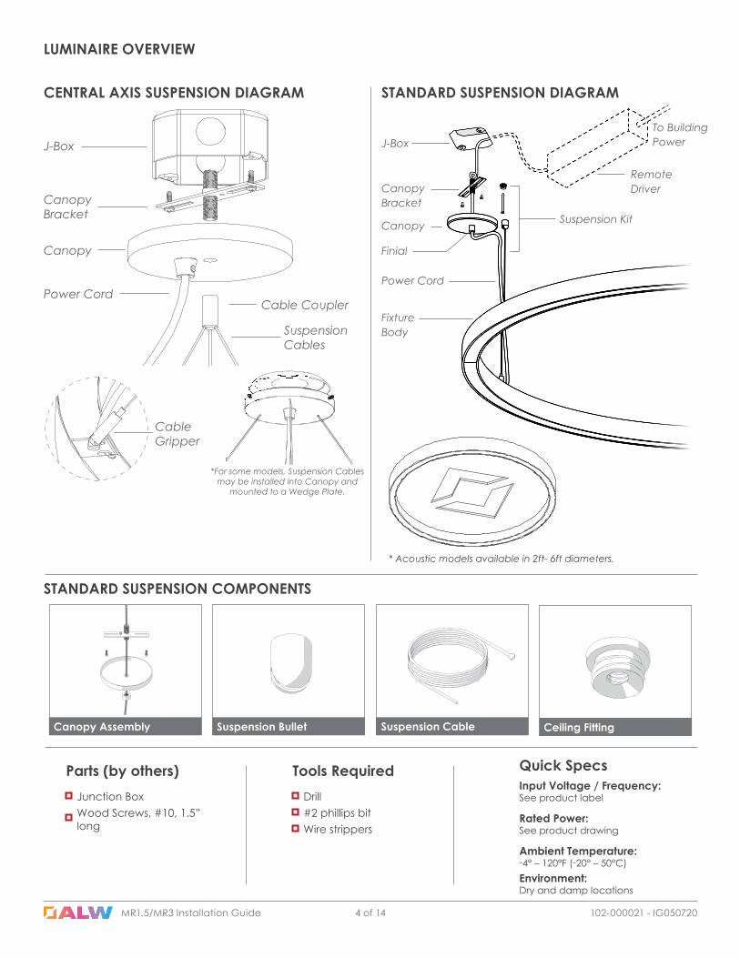
LUMINAIRE OVERVIEW
Drill#2 phillips bit
Tools Required
Wire strippers
Input Voltage / Frequency:See product label
Rated Power:See product drawing
Ambient Temperature:-4° – 120°F (-20° – 50°C)Environment:Dry and damp locations
Quick Specs
Junction Box
Parts (by others)
Wood Screws, #10, 1.5” long
STANDARD SUSPENSION DIAGRAMCENTRAL AXIS SUSPENSION DIAGRAM
STANDARD SUSPENSION COMPONENTS
Suspension BulletCanopy Assembly Suspension Cable Ceiling Fitting
J-Box
Canopy Bracket
Canopy
Power CordCable Coupler
Suspension Cables
Cable Gripper
*For some models, Suspension Cables may be installed into Canopy and
mounted to a Wedge Plate.
* Acoustic models available in 2ft- 6ft diameters.

MR1.5/MR3 Installation Guide 5 of 14 102-000021 - IG050720MR1.5/MR3 Installation Guide
Install remote driver J-Box(es) in an accessible/serviceable location. Run low voltage wire from Remote Driver J-Box to Canopy J-Box in accordance with local/state/federal regulations.
3 Install Remote Driver J-Box
Canopy Fittings may also be mounted using toggle bolts.
4B Install Canopy Fitting - Toggle Bolts
Canopy Fittings may also be mounted on 1/4”-20 Threaded Rods.
4C Install Canopy Fitting - 1/4”-20 Threaded Rods
Installation: Prepare Ceiling Installation: Standard Suspension
Canopy Fittings may be installed directly into framing with appropriate hardware.
4A Install Canopy Fitting - FramingSee final/record drawings for mounting locations. Install framing or 1/4-20 ceiling rods with consideration for alignment of wiring and suspension mounting locations.
1 See Final/Record Drawings for Mounting Locations
SAMPLE DRAWING
Install Canopy J-Box (sold separately) at power feed location per final/record drawing.
2 Install Canopy J-Box
SAMPLE
DRAWIN
G
MR1.5/MR3 Installation Guide 6 of 14 102-000021 - IG050720
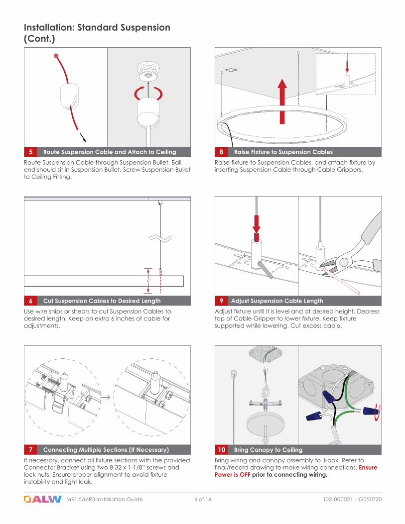
Bring wiring and canopy assembly to J-box. Refer to final/record drawing to make wiring connections. Ensure Power is OFF prior to connecting wiring.
10 Bring Canopy to Ceiling
Route Suspension Cable through Suspension Bullet. Ball end should sit in Suspension Bullet. Screw Suspension Bullet to Ceiling Fitting.
5 Route Suspension Cable and Attach to Ceiling
Installation: Standard Suspension(Cont.)
6"
Use wire snips or shears to cut Suspension Cables to desired length. Keep an extra 6 inches of cable for adjustments.
6 Cut Suspension Cables to Desired Length 9 Adjust Suspension Cable LengthAdjust fixture until it is level and at desired height. Depress top of Cable Gripper to lower fixture. Keep fixture supported while lowering. Cut excess cable.
Raise fixture to Suspension Cables, and attach fixture by inserting Suspension Cable through Cable Grippers.
8 Raise Fixture to Suspension Cables
7 Connecting Multiple Sections (If Necessary)If necessary, connect all fixture sections with the provided Connector Bracket using two 8-32 x 1-1/8” screws and lock nuts. Ensure proper alignment to avoid fixture instability and light leak.
MR1.5/MR3 Installation Guide MR1.5/MR3 Installation Guide 7 of 14 102-000021 - IG050720
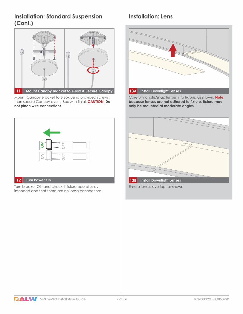
Mount Canopy Bracket to J-Box using provided screws, then secure Canopy over J-Box with finial. CAUTION: Do not pinch wire connections.
11 Mount Canopy Bracket to J-Box & Secure Canopy
Installation: Standard Suspension (Cont.)
Ensure lenses overlap, as shown.
13B Install Downlight Lenses
Carefully angle/snap lenses into fixture, as shown. Note: because lenses are not adhered to fixture, fixture may only be mounted at moderate angles.
13A Install Downlight Lenses
Installation: Lens
Turn breaker ON and check if fixture operates as intended and that there are no loose connections.
12 Turn Power On
MR1.5/MR3 Installation Guide 8 of 14 102-000021 - IG050720
Installation: Central Axis Suspension (CAS) - Cable Coupler
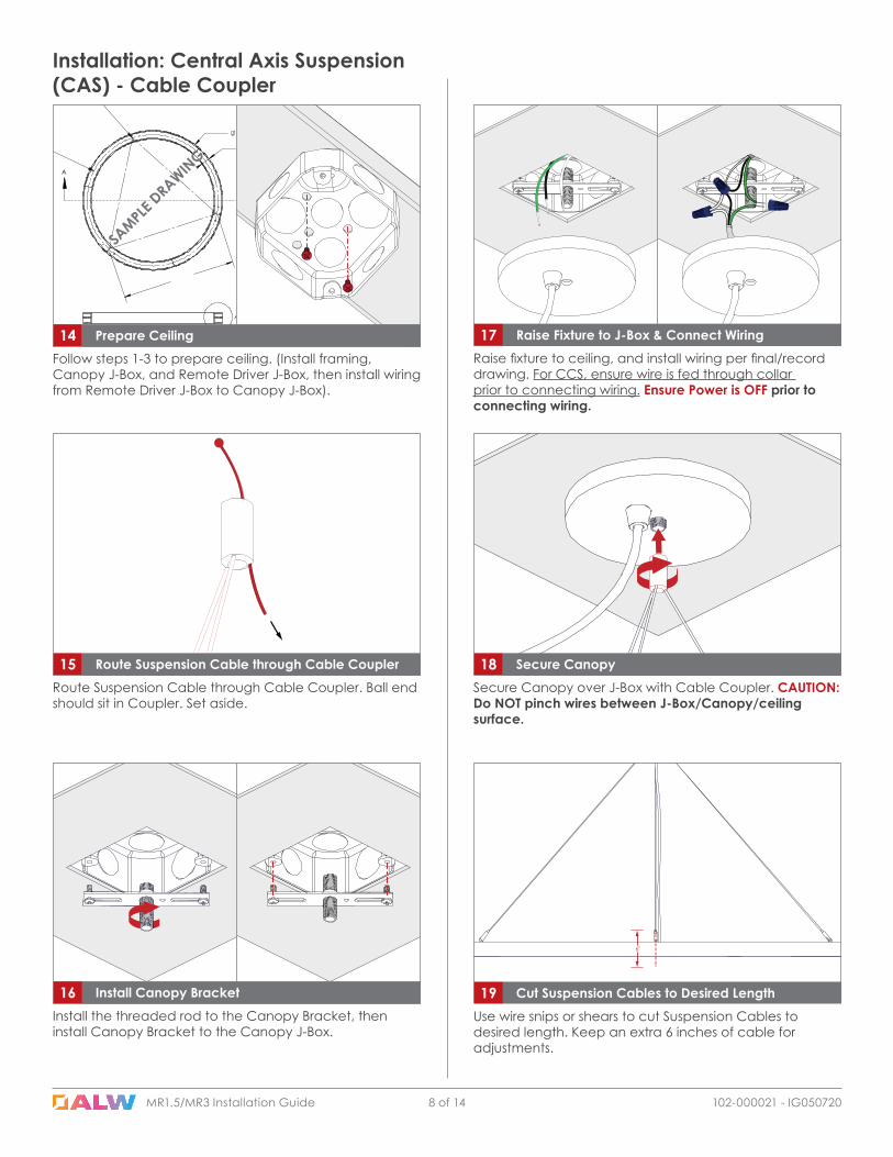
17 Raise Fixture to J-Box & Connect Wiring Raise fixture to ceiling, and install wiring per final/record drawing. For CCS, ensure wire is fed through collar prior to connecting wiring. Ensure Power is OFF prior to connecting wiring.
16 Install Canopy BracketInstall the threaded rod to the Canopy Bracket, then install Canopy Bracket to the Canopy J-Box.
Secure Canopy over J-Box with Cable Coupler. CAUTION: Do NOT pinch wires between J-Box/Canopy/ceiling surface.
18 Secure CanopyRoute Suspension Cable through Cable Coupler. Ball end should sit in Coupler. Set aside.
15 Route Suspension Cable through Cable Coupler
Follow steps 1-3 to prepare ceiling. (Install framing, Canopy J-Box, and Remote Driver J-Box, then install wiring from Remote Driver J-Box to Canopy J-Box).
14 Prepare Ceiling
SAMPLE
DRAWIN
G
6"
Use wire snips or shears to cut Suspension Cables to desired length. Keep an extra 6 inches of cable for adjustments.
19 Cut Suspension Cables to Desired Length
MR1.5/MR3 Installation Guide MR1.5/MR3 Installation Guide 9 of 14 102-000021 - IG050720
Installation: CAS - Cable Coupler (Cont.)
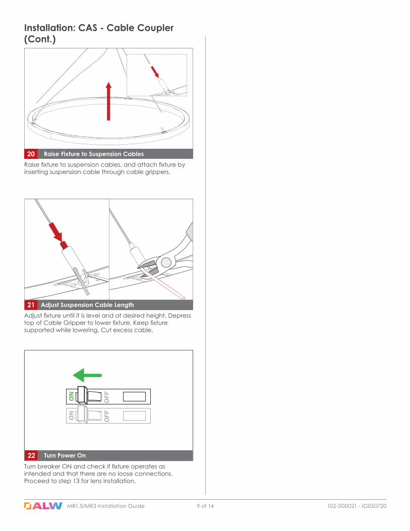
Turn breaker ON and check if fixture operates as intended and that there are no loose connections. Proceed to step 13 for lens installation.
22 Turn Power On
Raise fixture to suspension cables, and attach fixture by inserting suspension cable through cable grippers.
20 Raise Fixture to Suspension Cables
21 Adjust Suspension Cable LengthAdjust fixture until it is level and at desired height. Depress top of Cable Gripper to lower fixture. Keep fixture supported while lowering. Cut excess cable.
MR1.5/MR3 Installation Guide 10 of 14 102-000021 - IG050720
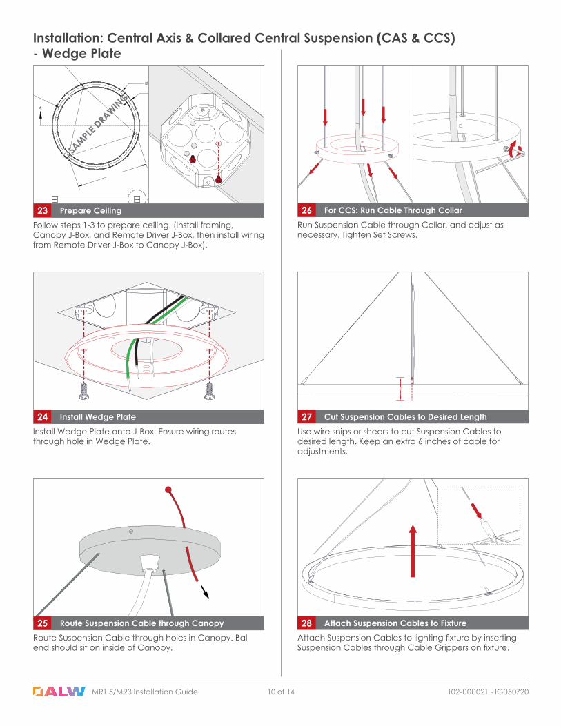
Installation: Central Axis & Collared Central Suspension (CAS & CCS) - Wedge Plate
Install Wedge Plate onto J-Box. Ensure wiring routes through hole in Wedge Plate.
24 Install Wedge Plate
Follow steps 1-3 to prepare ceiling. (Install framing, Canopy J-Box, and Remote Driver J-Box, then install wiring from Remote Driver J-Box to Canopy J-Box).
23 Prepare Ceiling
SAMPLE
DRAWIN
G
Route Suspension Cable through holes in Canopy. Ball end should sit on inside of Canopy.
25 Route Suspension Cable through Canopy
26 For CCS: Run Cable Through CollarRun Suspension Cable through Collar, and adjust as necessary. Tighten Set Screws.
6"
Use wire snips or shears to cut Suspension Cables to desired length. Keep an extra 6 inches of cable for adjustments.
27 Cut Suspension Cables to Desired Length
Attach Suspension Cables to lighting fixture by inserting Suspension Cables through Cable Grippers on fixture.
28 Attach Suspension Cables to Fixture
MR1.5/MR3 Installation Guide MR1.5/MR3 Installation Guide 11 of 14 102-000021 - IG050720
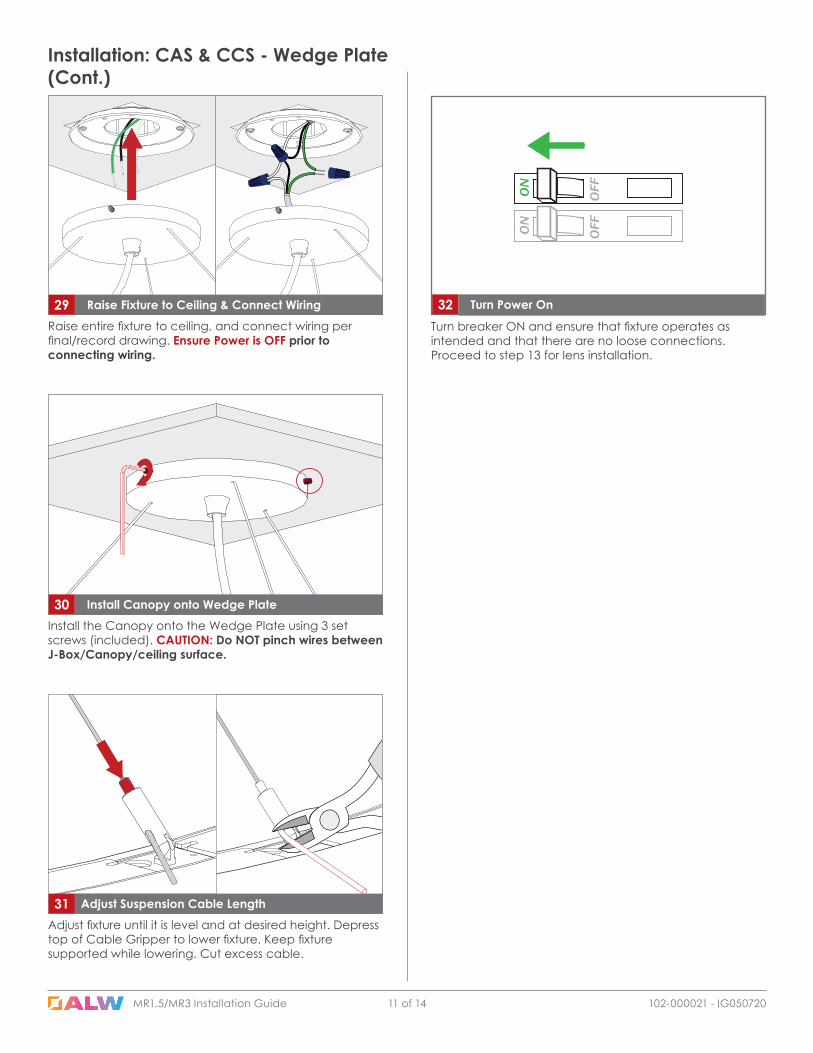
Installation: CAS & CCS - Wedge Plate (Cont.)
29 Raise Fixture to Ceiling & Connect Wiring Raise entire fixture to ceiling, and connect wiring per final/record drawing. Ensure Power is OFF prior to connecting wiring.
Install the Canopy onto the Wedge Plate using 3 set screws (included). CAUTION: Do NOT pinch wires between J-Box/Canopy/ceiling surface.
30 Install Canopy onto Wedge Plate
Turn breaker ON and ensure that fixture operates as intended and that there are no loose connections. Proceed to step 13 for lens installation.
32 Turn Power On
31 Adjust Suspension Cable LengthAdjust fixture until it is level and at desired height. Depress top of Cable Gripper to lower fixture. Keep fixture supported while lowering. Cut excess cable.
MR1.5/MR3 Installation Guide 12 of 14 102-000021 - IG050720
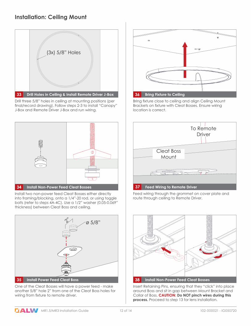
36 Bring Fixture to CeilingBring fixture close to ceiling and align Ceiling Mount Brackets on fixture with Cleat Bosses. Ensure wiring location is correct.
33 Drill Holes in Ceiling & Install Remote Driver J-BoxDrill three 5/8” holes in ceiling at mounting positions (per final/record drawing). Follow steps 2-3 to install “Canopy” J-Box and Remote Driver J-Box and run wiring.
Installation: Ceiling Mount
34 Install Non-Power Feed Cleat BossesInstall two non-power feed Cleat Bosses either directly into framing/blocking, onto a 1/4”-20 rod, or using toggle bolts (refer to steps 4A-4C). Use a 1/2” washer (0.05-0.069” thickness) between Cleat Boss and ceiling.
38 Install Non-Power Feed Cleat BossesInsert Retaining Pins, ensuring that they “click” into place around Boss and sit in gap between Mount Bracket and Collar of Boss. CAUTION: Do NOT pinch wires during this process. Proceed to step 13 for lens installation.
Feed wiring through the grommet on cover plate and route through ceiling to Remote Driver.
37 Feed Wiring to Remote Driver
To Remote Driver
Cleat Boss Mount
35 Install Power Feed Cleat BossOne of the Cleat Bosses will have a power feed - make another 5/8” hole 2” from one of the Cleat Boss holes for wiring from fixture to remote driver.
2” ø 5/8”
(3x) 5/8” Holes
MR1.5/MR3 Installation Guide 13 of 14 102-000021 - IG050720MR1.5/MR3 Installation Guide
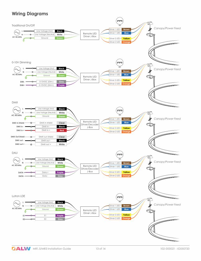
Wiring Diagrams
BrownBlue
Driver 1 LED +
Driver 1 LED -
YellowOrange
Driver 2 LED +
Driver 2 LED -
DC
BlackWhite GreenGround
Line Voltage (Hot)
Line Voltage (Neutral)
L
NAC 50/60Hz
Traditional On/Off
Remote LED Driver J-Box
BrownBlue
Driver 1 LED +
Driver 1 LED -
YellowOrange
Driver 2 LED +
Driver 2 LED -
DCBlackWhite Green
GreyPurple
Line Voltage (Hot)
Line Voltage (Neutral)
Ground
0-10VDC (Dim-)
0-10VDC (Dim+)
L
NAC 50/60Hz
DIM-
DIM+
0-10V Dimming
Remote LED Driver J-Box
BrownBlue
Driver 1 LED +
Driver 1 LED -
YellowOrange
Driver 2 LED +
Driver 2 LED -
DC
BlackWhite Green
ClearBlack
DMX in shield
DMX in -
Line Voltage (Hot)
Line Voltage (Neutral)
Ground
L
NAC 50/60Hz
DMX In Shield
DMX in -
RedDMX in +DMX in +
ClearBlack
DMX out shield
DMX out -
WhiteDMX out +
DMX Out Shield
DMX out -
DMX out +
DMX
Remote LED Driver/Decoder
J-Box
BrownBlue
Driver 1 LED +
Driver 1 LED -
YellowOrange
Driver 2 LED +
Driver 2 LED -
DCBlackWhite Green
PurpleGrey
Line Voltage (Hot)
Line Voltage (Neutral)
Ground
Data +
Data -
L
NAC 50/60Hz
DATA +
DATA -
DALI
Remote LED Driver/Decoder
J-Box
BrownBlue
Driver 1 LED +
Driver 1 LED -
YellowOrange
Driver 2 LED +
Driver 2 LED -
DCBlackWhite Green
PurpleGrey
Line Voltage (Hot)
Line Voltage (Neutral)
Ground
E1
E2
L
NAC 50/60Hz
E1
E2
Lutron LDE
Remote LED Driver J-Box
Canopy/Power Feed
Canopy/Power Feed
Canopy/Power Feed
Canopy/Power Feed
Canopy/Power Feed

MR1.5/MR3 Installation Guide 14 of 14 102-000021 - IG050720
Troubleshooting
Full Fixture does not illuminate • Ensure all wire connections are made.• Ensure fixture is wired correctly and power is on. • Check that circuit breaker is on and not off or tripped.• Class 2 LED remote driver may be defective.
Full fixture is flickering • 0-10V, DMX, and DALI Dimming Models: Ensure polarity is correct for DATA + and - connections. Swapping DATA + and - connections can cause flickering.
• TRIAC Dimming Models: Ensure a compatible TRIAC Forward Phase dimmer is connected to fixture. Call tech support for further information.
• Possible loose DATA + and - connections from fixture to 0-10V, DMX, or DALI control.
• Possible loose low voltage DC + or - connection from driver to LED. Call customer support.
Only a certified electrician can service and troubleshoot product field issues. Always turn main power off before servicing fixture.
Fixture section(s) do not illuminate
• Possible loose low voltage DC + or - connection between LED boards or from LED driver to LED boards.
• Some fixtures contain multiple LED drivers. In this case, it’s possible one of the drivers is defective, which will cause the LED connected to the driver not to illuminate. Call tech support.
Fixture section(s) are flickering • Possible loose low voltage DC + or - connection between LED boards.
Fixture does not dim • 0-10V, DMX, and DALI Dimming Models: Ensure polarity is correct for DATA + and - connections. Swapping DATA + and - connections can cause flickering. TEST.
• TRIAC Dimming Models: Ensure a compatible TRIAC Forward Phase dimmer is connected to fixture. Call tech support for further information.
• Possible loose DATA + and - connections from fixture to 0-10V, DMX, or DALI control.