
INSTALLATION INSTRUCTIONS - hvac.com the following guidelines to select a suitable location for...
16
02/06 *2P0206* 505,174M *P505174M* Page 1 RETAIN THESE INSTRUCTIONS FOR FUTURE REFERENCE E 2005 Lennox Industries Inc. Dallas, Texas, USA INSTALLATION INSTRUCTIONS 13GCS SERIES UNITS GAS PACKAGED UNITS (2−5 TONS) 505,174M (38152A073) 02/06 Table of Contents Unit Dimensions 2 . . . . . . . . . . . . . . . . . . . . . . . . . . . . . . . Parts Arrangement 3 . . . . . . . . . . . . . . . . . . . . . . . . . . . . . Shipping & Packing List 3 . . . . . . . . . . . . . . . . . . . . . . . . . General 3 . . . . . . . . . . . . . . . . . . . . . . . . . . . . . . . . . . . . . . . Safety Information 3 . . . . . . . . . . . . . . . . . . . . . . . . . . . . . . Location Selection 4 . . . . . . . . . . . . . . . . . . . . . . . . . . . . . . Rigging & Setting Unit 5 . . . . . . . . . . . . . . . . . . . . . . . . . . Clearances 5 . . . . . . . . . . . . . . . . . . . . . . . . . . . . . . . . . . . . Installing Vent Hood 6 . . . . . . . . . . . . . . . . . . . . . . . . . . . . Existing Common Vent Systems 6 . . . . . . . . . . . . . . . . . . Condensate Drain 7 . . . . . . . . . . . . . . . . . . . . . . . . . . . . . . Filters 7 . . . . . . . . . . . . . . . . . . . . . . . . . . . . . . . . . . . . . . . . . Supply & Return Connections 7 . . . . . . . . . . . . . . . . . . . . Compressors 8 . . . . . . . . . . . . . . . . . . . . . . . . . . . . . . . . . . Gas Supply and Piping 8 . . . . . . . . . . . . . . . . . . . . . . . . . . Electrical 10 . . . . . . . . . . . . . . . . . . . . . . . . . . . . . . . . . . . . . Blower Speed Settings 12 . . . . . . . . . . . . . . . . . . . . . . . . . Cooling Start−Up 13 . . . . . . . . . . . . . . . . . . . . . . . . . . . . . . Heating Start−up 14 . . . . . . . . . . . . . . . . . . . . . . . . . . . . . . Unit Controls 15 . . . . . . . . . . . . . . . . . . . . . . . . . . . . . . . . . Condenser Fan Clearances 16 . . . . . . . . . . . . . . . . . . . . . Maintenance 17 . . . . . . . . . . . . . . . . . . . . . . . . . . . . . . . . . . Repair Parts & Accessories 17 . . . . . . . . . . . . . . . . . . . . . WHAT TO DO IF YOU SMELL GAS: Do not store or use gasoline or other flammable vapors and liquids in the vicinity of this or any other ap- pliance. Installation and service must be performed by a qualified installer, service agency or the gas supplier. D Do not try to light any appliance. D Do not touch any electrical switch; do not use any phone in your building. D Immediately call your gas supplier from a neighbor’s phone. Follow the gas supplier’s instructions. D If you cannot reach your gas supplier, call the fire department. FIRE OR EXPLOSION HAZARD. Failure to follow safety warnings exact- ly could result in serious injury, death, or property damage. WARNING D Leave the building immediately. Litho U.S.A.
Transcript of INSTALLATION INSTRUCTIONS - hvac.com the following guidelines to select a suitable location for...

02/06
��������505,174M
��������Page 1
RETAIN THESE INSTRUCTIONSFOR FUTURE REFERENCE
� 2005 Lennox Industries Inc.
Dallas, Texas, USA
INSTALLATIONINSTRUCTIONS
13GCS SERIES UNITS
GAS PACKAGED UNITS (2−5 TONS)505,174M
(38152A073) 02/06
Table of Contents
Unit Dimensions 2. . . . . . . . . . . . . . . . . . . . . . . . . . . . . . . Parts Arrangement 3. . . . . . . . . . . . . . . . . . . . . . . . . . . . . Shipping & Packing List 3. . . . . . . . . . . . . . . . . . . . . . . . . General 3. . . . . . . . . . . . . . . . . . . . . . . . . . . . . . . . . . . . . . . Safety Information 3. . . . . . . . . . . . . . . . . . . . . . . . . . . . . . Location Selection 4. . . . . . . . . . . . . . . . . . . . . . . . . . . . . . Rigging & Setting Unit 5. . . . . . . . . . . . . . . . . . . . . . . . . . Clearances 5. . . . . . . . . . . . . . . . . . . . . . . . . . . . . . . . . . . . Installing Vent Hood 6. . . . . . . . . . . . . . . . . . . . . . . . . . . . Existing Common Vent Systems 6. . . . . . . . . . . . . . . . . . Condensate Drain 7. . . . . . . . . . . . . . . . . . . . . . . . . . . . . . Filters 7. . . . . . . . . . . . . . . . . . . . . . . . . . . . . . . . . . . . . . . . . Supply & Return Connections 7. . . . . . . . . . . . . . . . . . . . Compressors 8. . . . . . . . . . . . . . . . . . . . . . . . . . . . . . . . . . Gas Supply and Piping 8. . . . . . . . . . . . . . . . . . . . . . . . . . Electrical 10. . . . . . . . . . . . . . . . . . . . . . . . . . . . . . . . . . . . . Blower Speed Settings 12. . . . . . . . . . . . . . . . . . . . . . . . . Cooling Start−Up 13. . . . . . . . . . . . . . . . . . . . . . . . . . . . . . Heating Start−up 14. . . . . . . . . . . . . . . . . . . . . . . . . . . . . . Unit Controls 15. . . . . . . . . . . . . . . . . . . . . . . . . . . . . . . . . Condenser Fan Clearances 16. . . . . . . . . . . . . . . . . . . . . Maintenance 17. . . . . . . . . . . . . . . . . . . . . . . . . . . . . . . . . . Repair Parts & Accessories 17. . . . . . . . . . . . . . . . . . . . .
WHAT TO DO IF YOU SMELL GAS:Do not store or use gasoline or otherflammable vapors and liquids in thevicinity of this or any other ap-pliance.
Installation and service must beperformed by a qualified installer,service agency or the gas supplier.
� Do not try to light any appliance.
� Do not touch any electrical switch; do notuse any phone in your building.
� Immediately call your gas supplier from aneighbor’s phone. Follow the gas supplier’sinstructions.
� If you cannot reach your gas supplier, callthe fire department.
FIRE OR EXPLOSION HAZARD.
Failure to follow safety warnings exact-ly could result in serious injury, death,or property damage.
WARNING
� Leave the building immediately.
Litho U.S.A.

GAS PIPING INLET
HORIZONTALSUPPLY AIR
OPENING
BACK VIEW
END VIEW
TOP VIEW
A
B
FLUEOUTLET
FRONT VIEW
HORIZONTALRETURN AIR
OPENING
C
L
F G
H
JK
DE E
D
DOWN−FLOWSUPPLY AIR
OPENING
DOWN−FLOWRETURN AIR
OPENING
ED
ED
END VIEWCONDENSATE DRAIN
ELECTRICAL INLET
2−1/2 (64)2−1/2 (64)
2−3/4(70)
2−3/4(70)
2−3/4(70)
2−1/2 (64)
3−1/4 (83)
4−1/4 (108)
AA
CCDD
FF
BB
EE
Page 2
13GCS Unit Dimensions − inches (mm)
ModelCorner Weights
Center OfGravityModel
Number AA BB CC DD EE FFNumber
lbs. lbs. lbs. lbs. in. in.
13GCS−24 74 94 125 97 15.5 28.5
13GCS−30 74 94 125 97 15.5 28.5
13GCS−36 84 101 126 105 16 29.5
13GCS−42 108 136 176 140 20 33
13GCS−48 112 137 177 144 20 33.5
13GCS−60 117 143 184 151 20 33.5
Model NoA B C D E F
Model No.in. mm in. mm in. mm in. mm in. mm in. mm
13GCS−2413GCS−3013GCS−36
34−1/4 870 65−3/8 1661 36−1/2 927 11−1/4 286 17−1/4 438 20 508
13GCS−4213GCS−4813GCS−60
38−1/4 972 75 1905 46 1168 11−1/4 286 19−1/4 489 22 559
Model NoG H J K L
Model No.in. mm in. mm in. mm in. mm in. mm
13GCS−2413GCS−3013GCS−36
8−1/2 216 3 76 20−1/4 514 4−1/2 114 19 483
13GCS−4213GCS−4813GCS−60
9−1/4 241 3−1/4 83 22−1/4 572 4 102 16−1/4 413

Page 3
Parts Arrangement
Shipping & Packing List
1 − Assembled gas package unit
1 − Vent hood assembly with screen and screws
As soon as the unit is received, it should be inspected forpossible damage during transit. If you find any damage,immediately contact the last carrier.
General
These installation instructions are intended as a generalguide only, for use by an experienced, qualified contractor.
The Merit® Series 13GCS units are single−package airconditioners designed for outdoor installation on a rooftopor a slab.
The unit must be sized based on heat loss and heat gaincalculations made according to the methods of the AirConditioning Contractors of America (ACCA).
The units are shipped assembled. All piping, refrigerantcharge, and electrical wiring are factory−installed andtested. The units require electric power, gas piping,condensate drain and duct connections at the point ofinstallation. In addition, the heating vent hood must beinstalled before the unit is placed into operation
Safety Information
WARNINGProduct contains fiberglass wool.
Disturbing the insulation in this product duringinstallation, maintenance, or repair will expose youto fiberglass wool dust. Breathing this may causelung cancer. (Fiberglass wool is known to the Stateof California to cause cancer.)
Fiberglass wool may also cause respiratory, skin,and eye irritation.
To reduce exposure to this substance or for furtherinformation, consult material safety data sheetsavailable from address shown below, or contact yoursupervisor.
Lennox Industries Inc.
P.O. Box 799900Dallas, TX 75379−9900

Page 4
WARNINGImproper installation, adjustment, alteration, serviceor maintenance can cause property damage, personalinjury or loss of life. Installation and service must beperformed by a qualified installer or service agency.
These units must be installed in accordance with allapplicable national and local safety codes.
These instructions are intended as a general guide and donot supersede local codes in any way. Consult authoritieshaving jurisdiction before installation.
If components are to be added to a unit to meet local codes,they are to be installed at the dealer’s and/or customer’sexpense.
These units are design listed by UL in both the UnitedStates and Canada as follows:
� For use as a forced air furnace with cooling.
� For outdoor installation only.
� For installation on combustible material.
� For use with natural gas or L.P./propane gas only. Useof L.P./propane gas requires installation of an L.P. con-version kit, which must be ordered separately.
These units are not suitable for use with conventionalventing systems.
The following safety requirements must also be met whenthe 13GCS units are installed:
1 − Use only with the type of fuel approved for use with thisappliance. Refer to the unit rating plate.
2 − Position, locate and install the 13GCS unit only as out-lined in these instructions.
3 − Provide adequate clearance around the vent hood asspecified in these instructions.
4 − Do not use an open flame to check for gas leaks. Use acommercially available soap solution, which has beendesigned specifically to check for gas leaks. Refer tothe Gas Supply and Piping section.
5 − Check the unit operation after start−up to make surethat the 13GCS is operating within the intended tem-perature rise range. The duct system must be de-signed to provide an external static pressure within theallowable range. Refer to the unit rating plate.
Lennox does not recommend the use of 13GCS units as aconstruction heater during any phase of construction. Verylow return air temperatures, harmful vapors and operationof the unit with clogged or misplaced filters will damage theunit.
13GCS units may be used for heating of buildings or struc-tures under construction, if the following conditions aremet:
� The vent hood must be installed per these installation in-
structions.
� A room thermostat must control the unit. The use of
fixed jumpers that will provide continuous heating is not
allowed.
� The return air duct must be provided and sealed to the
unit.
� Return air temperature range between 60°F (16°C) and
80°F (27°C) must be maintained.
� Air filters must be installed in the system and must be
maintained during construction.
� Air filters must be replaced upon construction comple-
tion.
� The input rate and temperature rise must be set per the
unit rating plate.
� One hundred percent (100%) outdoor air must be pro-
vided for combustion air requirements during construc-
tion. Installation of this unit in its intended outdoor loca-
tion will accomplish this.
� The heat exchanger, components, duct system, air fil-
ters and evaporator coil must be thoroughly cleaned fol-
lowing final construction clean−up.
� The unit operating conditions (including ignition, input
rate, temperature rise and venting) must be verified ac-
cording to these installation instructions.
NOTE − The Commonwealth of Massachusetts stipu-
lates these additional requirements:
� Gas furnaces shall be installed by a licensed plumb-
er or gas fitter only.
� The gas cock must be �T handle" type.
� When flexible connectors are used, the maximum
length shall not exceed 36".
Location Selection
Use the following guidelines to select a suitable location forthese units.
1 − Unit is designed for outdoor installation only. Unit mustbe installed so all electrical components are protectedfrom water.
2 − Condenser coils must have an unlimited supply of air.
3 − For ground level installation, use a level pre−fabricatedpad or use a level concrete slab with a minimum thick-ness of 4 inches. The length and width should be atleast 6 inches greater than the unit base. Do not tie theslab to the building foundation.
4 − Maintain level within a tolerance of 1/4 inch maximumacross the entire length or width of the unit.
5 − Do not locate the unit where the combustion air supplywill be exposed to any corrosive substance, includingthe following:Permanent wave solutions,Chlorinated waxes or cleaners,Chlorine−based swimming pool chemicals,Water−softening chemicals,De−icing salts or chemicals,Carbon tetrachloride,Halogen−type refrigerants,Cleaning solvents (e.g., perchloroethylene),Printing inks, paint removers, varnishes, etc.,Cements and glues,Anti−static fabric softeners used in clothes dryers,Masonry acid−washing materials,Chlorinated laundry products,Hydrochloric acid.

Page 5
Rigging & Setting Unit
Exercise care when moving the unit. Do not remove anypackaging until the unit is near the place of installation. Anoptional lifting lug kit (92M51) may be purchasedseparately for use in rigging the unit for lifting. Spreaderswhose length exceeds the largest dimension across theunit MUST be used across the top of the unit.
CAUTIONBefore lifting a unit, make sure that the weight is dis-tributed equally on the cables so that it will lift evenly.
Figure 1
Accessory Lift Kit
Lifting BracketAccessory
Sheet MetalScrew
Units may also be moved or lifted with a forklift while still inthe factory supplied packaging.
NOTE − Length of forks must be a minimum of 42 inches.
Clearances
All units require certain clearances for proper operationand service. Refer to figure 2 for the clearances requiredfor combustible construction, servicing, and proper unitoperation.
NOTE − Do not permit overhanging structures or shrubs toobstruct condenser air discharge outlet or vent outlet.
In the U.S. units may be installed on combustible floorsmade from wood or class A, B, or C roof covering material.In Canada, units may be installed on combustible floors.
The products of combustion are discharged through ascreened vent outlet in the front mullion.
Install the unit so that the products of combustion will notdamage the outer building structure.
The vent outlet must be at least 4 feet below, 4 feethorizontally from and 1 foot above any door, window orgravity air inlet into the building. In addition, install the unitso that the vent outlet is at least 3 feet above any forced airinlet located within 10 feet.
Clearances to the vent outlet must also be consistent withthe requirements of the current National Fuel Gas Code(Z223.1) and/or the standards of the current CSA B149codes.
Figure 2
Service Clearances
3* (76)
48 (1219)
30(762)
24(610)
* Maintain 18 in. (457 mm) service clearance foraccessory maintenance, if equipped.NOTE − Top Clearance − 36 in. (914 mm)NOTE − Entire perimeter of unit base requiressupport when elevated above mounting surface.
Figure 3 shows the minimum clearances to combustiblesrequired above and below the vent hood. The minimumclearance in front of the vent hood is 24 inches.
Install the unit so that snow accumulation will not restrictthe flow of the flue products. Allow a required minimumhorizontal clearance of 4 feet from electric meters, gasmeters, regulators and relief equipment. In addtion to theabove requirements, ensure that unwanted ice caused bycondensate is not allowed to accumulate around the unit.Do not locate the unit on the side of the building where theprevailing winter winds could trap moisture, causing it tofreeze on the walls or on overhangs (under eaves). Thevent outlet should not discharge flue products on asidewalk, patio or other walkway where the condensatecould cause the surface to become slippery.
Do not install the unit so that the products ofcombustion will be allowed to accumulate within aconfined space and recirculate.
Figure 3
Minimum ClearanceAbove�Vent Hood:Distance from�Topof�Vent Hoodto�Top of Unit
Minimum ClearanceBelow�Vent Hood:Distance from Bottomof�Vent Hood to Baseof Unit
Minimum Clearances to Combustible MaterialsAbove and Below Vent Hood

Page 6
Vent Hood Installation
The vent hood, screen and screws are shipped inside theunit in the plastic bag which contains the installationinstructions.
1 − Insert the vent screen into the vent tube Once in-serted, the screen should be flush with the end of thetube as shown in figure 4.
Vent Hood Installation
Figure 4
Screen
Vent Hood
Top�View
Slotted side of
vent hood faces
condenser coil.
Screen
Vent�Tube
Front�View
Screen is pre−formed
Vent�Tube
NOTE −Screws
should passthroughsides of
screen tohold screen
in place.
2 − Position the vent hood over the vent tube so that theslotted side of the hood faces the condenser coil. Usethe four sheet metal screws (provided) to secure thevent hood to the vent tube. The screws should passthrough the sides of the screen in order to hold thescreen in place.
The vent hood must be installed prior to unit start−up.
Existing Common Vent Systems
The 13GCS packaged unit may replace an existing fur-nace which is being removed from a venting system com-monly run with separate gas appliances. In this case, theexisting vent system is likely to be too large to properlyvent the remaining attached appliances.
Conduct the following test while each appliance is operat-ing and the other appliances (which are not operating) re-main connected to the common venting system. If theventing system has been installed improperly, you mustcorrect the system as indicated in the general venting re-quirements section.
1 − Seal any unused openings in the common venting sys-
tem.
2 − Inspect the venting system for proper size and horizontal
pitch. Determine that there is no blockage, restriction,
leakage, corrosion, or other deficiencies which could
cause an unsafe condition.
3 − Close all building doors and windows and all doors be-
tween the space in which the appliances remaining
connected to the common venting system are located
and other spaces of the building. Turn on clothes dry-
ers and any appliances not connected to the common
venting system. Turn on any exhaust fans, such as
range hoods and bathroom exhausts, so they will oper-
ate at maximum speed. Do not operate a summer ex-
haust fan. Close fireplace dampers.
4 − Follow the lighting instructions. Turn on the appliance
that is being inspected. Adjust the thermostat so that
the appliance operates continuously.
5 − After the main burner has operated for 5 minutes, test
for leaks of flue gases at the draft hood relief opening.
Use the flame of a match or candle, or smoke from a
cigarette, cigar, or pipe.
6 − After determining that each appliance connected to the
common venting system is venting properly, (step 3)
return all doors, widows, exhaust fans, fireplace damp-
ers, and any other gas−burning appliances to their pre-
vious mode of operation.
7 − If a venting problem is found during any of the preced-
ing tests, the common venting system must be modi-
fied to correct the problem.
Resize the common venting system to the minimum
vent pipe size determined by using the appropriate
tables in Appendix G. (These are in the current stan-
dards of the National Fuel Gas Code
ANSI-Z223.1/NFPA 54 in the USA, and the appropri-
ate Category 1 Natural Gas and Propane appliances
venting sizing tables in the current standards of the
CSA B149 Natural Gas and Propane Installation
Codes in Canada.)
Condensate Drain
The 13GCS unit is equipped with a 3/4 inch FPT couplingfor condensate line connection. Plumbing must conform tolocal codes. Use a sealing compound on male pipethreads.
The drain line must be properly trapped and routed to asuitable drain. See figure 5 for proper drain arrangement.The drain line must pitch to an open drain or pump aminimum of 1 inch per 10 feet to prevent clogging of theline. Seal around drain connection with suitable material toprevent air leakage into return air system.
Drain piping should not be smaller than drain connection atcoil. An open vent in drain line will some times be requireddue to line length, friction and static pressure. Drainsshould be constructed in a manner to facilitate future clean-ing.
NOTE − The condensate drain line MUST be trapped toprovide proper drainage.
CAUTIONCondensate line connection must be hand−tight-ened. Do not use tools.

Page 7
ÁÁÁÁÁÁÁÁÁÁÁÁÁÁÁÁÁÁ
unit
Minimum Pitch1 in. (25 mm) per10’ (3 m) of line
mountingframe
Figure 5
openvent
Trap must be deep enough to offset maximumstatic difference (Generally, 3 inches minimum).
Typical Condensate Drain
Filters
Filters are not factory−supplied with the unit; however,optional internally installed filter kits are available. Filter kit92M54 is used with 2, 2−1/2 and 3−ton units. Filter kit 92M55is used with 3−1/2, 4 and 5−ton units. The filter kitsaccommodate the use of 1", 2" or 4" filters. If the optionalfilter kit is not used, a filter must be field−installed.
Filters must always be installed ahead of evaporator coiland must be kept clean or replaced. Dirty filters will reducethe airflow of the unit. Filter sizes are shown in table 1.
Table 1Unit Filter Size
Unit Model Filter Size Filter Quantity
−24, −30, −36 20 in. X 25 in. 1
−42, −48, −60 16 in. X 25 in. 2
Supply & Return Duct Connections
The duct system should be designed and sized accordingto the methods in Manual Q of the Air ConditioningContractors of America (ACCA).
A closed return duct system shall be used. This shall notpreclude use of economizers or outdoor fresh air intake. Itis recommended that supply and return duct connectionsat the unit be made with flexible joints.
The supply and return air duct systems should be designedfor the CFM and static requirements of the job. Theyshould NOT be sized by simply matching thedimensions of the duct connections on the unit.
CAUTIONWhen fastening duct system to side duct flanges onunit, insert screws through duct flanges only. Do notinsert screws through casing. Outdoor duct must beinsulated and waterproofed.
The 13GCS unit is shipped ready for horizontal airdischarge (side duct connections). If bottom air discharge
is desired, the covers must be removed from the supplyand return air openings on the bottom of the unit andre−installed to cover the side openings.
Figure 6
Removing Supply and ReturnAir Opening Covers
Base1.�Remove screw and lift.2.�Slide cover to free back pin.
1
2
Compressors
Units are shipped with the compressor mountingsfactory−adjusted and ready for operation.
CAUTIONDo not loosen compressor mounting bolts.
Gas Supply and Piping
Check the unit rating plate to confirm whether unit isequipped for use with natural gas or LP/propane. Ifconversion is required use the approved conversion kit.
NOTE − Units are shipped equipped for natural gas, but canbe converted to LP/propane with a conversion kit. Conver-sion must be performed by an approved licensed pipefitter or technician.
All LP/propane gas equipment must conform to the safetystandards of the National Fire Protection Association.
Complete information regarding tank sizing forvaporization, recommended regulator settings, and pipesizing is available from most regulator manufacturers andLP/propane gas suppliers.
Proper sizing of gas piping depends on the cubic feet perhour of gas flow required, specific gravity of the gas andlength of run. In the United States, the current National FuelGas Code Z223.1 should be followed in all cases unlesssuperseded by local codes or gas company requirements.Refer to tables 2 and 3. In Canada, refer to the current CSAB.149 installation codes.
Table 2Gas Heat Application Data
UnitHeating Size
Input Rating(Btu)
Output Rating(Btu)
Gas Capacity*(FT3 / HR)
68 67,500 54,000 63
83 82,500 66,000 77
90 90,000 72,000 84
110 110,000 88,000 102
138 137,500 110,000 128
*Based on 1075 Btu per cubic foot of natural gas.

Page 8
Before connecting piping, check with gas company orauthorities having jurisdiction for local codes or require-ments. When installing gas supply piping, length of runfrom gas meter must be considered in determining pipesize for 0.5 inch w.c. maximum pressure drop. Do notuse supply pipe smaller than unit gas connection. Fornatural gas unit, supply pressure at the unit gas connec-tion must be a minimum of 5 inches w.c. and a maximumof 10.5 w.c. For LP/propane gas units, supply pressureat the unit gas connection must be a minimum of 11 inch-es w.c. and a maximum of 13.0 inches w.c.
Table 3Gas Pipe Capacity−FT3 / HR
Length in FeetNominal Iron Pipe Size (inches)
Length in Feet1/2 in. 3/4 in. 1 in. 1−1/4 in.
10 132 278 520 1050
20 92 190 350 730
30 73 152 285 590
40 63 130 245 500
50 56 115 215 440
60 50 105 195 400
70 46 96 180 370
80 43 90 170 350
90 40 84 160 320
100 38 79 150 305
The gas supply piping should be routed through the grom-met on the side of the unit. Refer to figure 7.
Figure 7
Gas Piping and Electrical Conduit Access
Gas Line Entry
ThermostatEntry
Line VoltageEntry
When making piping connections, a drip leg should beinstalled on vertical runs to serve as a trap for sediment orcondensate. A 1/8 inch N.P.T. tap accessible for test gaugeconnection must be provided in field piping upstream fromgas supply connection to unit. Install a ground joint unionbetween gas control manifold and the manual main shut−off valve. See figure 8.
Compounds used on threaded joints of gas piping shall beresistant to the action of propane/LP gases.
Figure 8
unitground joint
union
field provided1/8 in. pressure tap
manual mainshut−off valve
dripleg
gas pipingsupport
Drip Leg Installation
Pressure Test Gas Piping
When pressure testing gas lines, the gas valve must be dis-connected and isolated. Gas valve can be damaged if sub-jected to more than 0.5 psig (14 inch w.c.). See figure 9.
If test pressure is equal to or less than 0.5 psig (14 inchw.c.) shutoff the manual main shut-off valve before pres-sure testing to isolate unit from gas supply system.
gas valve cap
Manual Main Shut−off Valve Will Not Hold TestPressures in Excess of 0.5 PSIG (14 in. w.c.)
Figure 9
unit
Isolate Gas Valve To Pressure Test
NOTE − Codes may require that manual main shut off valve
and union (furnished by installer) be installed in gas line ex-
ternal to unit. Union must be of the ground joint type.
Danger of explosion. Can cause injury orproduct or property damage. Do not usematches, candles, flame or other sourcesof ignition to check for leaks.
WARNING!
After gas piping is complete, carefully check all piping con-nections (factory and field) for gas leaks. Use soap solutionor other preferred means.NOTE − In case of emergency shutdown, shut off main
manual gas valve and disconnect main power to unit.
These devices should be properly labeled by installer.
The heating value of the gas may differ with locality. Thevalue should be checked with the local gas utility.

Page 9
NOTE − There may be a local gas utility requirement speci-fying a minimum diameter for gas piping. All units require a1/2 inch pipe connection at the gas valve.
Gas piping recommendations:
1 − A drip leg and a ground joint union must be installed inthe gas piping.
A ground joint union is recommended by the man-ifold/valve.
2 − When required by local codes, a manual shut-off valvemay have to be installed outside of the unit.
3 − Use pipe thread sealing compound resistant to pro-pane gas sparingly on male threads.
4 − The gas supply should be a separate line and installedin accordance with all safety codes. After the gas con-nections have been completed, open the main shut-offvalve admitting normal gas pressure to the mains.Check all joints for leaks with soap solution or othermaterial suitable for the purpose.
CAUTIONSome soaps used for leak detection are corrosive tocertain metals. Carefully rinse piping thoroughly af-ter leak test has been completed. Do not usematches, candles, flame or other sources of ignitionto check for gas leaks.
5 − The unit and its individual manual shut-off valve mustbe disconnected from the gas supply piping systemduring any pressure testing of that system at test pres-sures in excess of 1/2 PSIG (3.48kPa).
IMPORTANTThe unit must be isolated from the gas supply pipingsystem by closing its individual manual shut−offvalve during any pressure testing of the gas supplypiping system at test pressures equal to or less than1/2 psig. See figure 9.
The unit and its individual shut−off valve must be dis-connected from the gas supply piping system duringany pressure testing of the system at test pressuresgreater than 1/2 psig.
6 − A 1/8 inch N.P.T. plugged tapping, accessible for testgage connections, must be installed immediately up-stream of the gas supply connection to the furnace.
Electrical
All wiring should be done in accordance with thecurrent National Electric Code ANSI/NFPA No. 70 in theUnited States. In Canada, wiring must be done inaccordance with the current CSA C22.2 Part 1. Localcodes may take precedence.
Use wiring with a temperature limitation of 75�C min.; runthe 208 or 230 volt, 60 hertz electric power supply through afused disconnect switch to control box of unit and connect
as shown in the wiring diagram located on the inside of thecontrol access panel.
Unit must be electrically grounded in accordance with localcodes or in the absence of local codes with the NationalElectric Code, ANSI/NFPA No. 70 (latest edition) or CSAC22.2 Part 1 (latest edition).
Power supply to the unit must comply with all applicablecodes and NEC or CEC. A fused disconnect switch shouldbe field provided for the unit. The switch must be separatefrom all other circuits. If any of the wire supplied with theunit must be replaced, replacement wire must be of thetype shown on the wiring diagram.
Electrical wiring must be sized to carry minimum circuitampacity marked on the unit. USE COPPERCONDUCTORS ONLY. Each unit must be wired with aseparate branch circuit and be properly fused.
CAUTIONWhen connecting electrical power and control wir-ing to the unit, waterproof type connectors MUST beused so that water or moisture cannot be drawn intothe unit during normal operation.
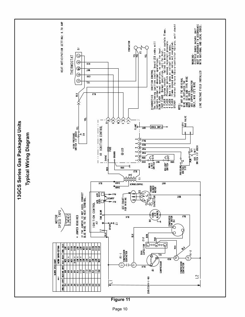
See figure 10 for field connection of line voltage wiring. Seefigure 11 for typical wiring diagram.
208/230 Line Voltage Wiring
NOTE − If 208 voltage is supplied, transformerconnections must be made.
L1
groundlug
L2
Figure 10
contactor
fused disconnect switch(furnished by installer)
Thermostat
The room thermostat should be located on an inside wallwhere it will not be subject to drafts, sun exposure or heatfrom electrical fixtures or appliances. Followmanufacturer’s instructions enclosed with thermostat forgeneral installation procedure. Color coded insulated wires(# 18 AWG) should be used to connect thermostat to unit.Four wires are required for cooling.
Heat Anticipator Setting
It is important that the anticipator setpoint be correct. Toohigh of a setting will result in longer heat cycles and agreater temperature swing in the conditioned space.Reducing the value below the correct setpoint will giveshorter �ON" cycles and may result in the lowering of thetemperature within the conditioned space.
Heat Anticipator Setting: 0.70 AMP
Page 10
Figure 11
13
GC
S S
eri
es
Ga
s P
ac
ka
ge
d U
nit
s
Typ
ical
Wir
ing
Dia
gra
m

Page 11
Blower Speed Settings
Electric shock hazard. Can cause injury ordeath. Before attempting to perform anyservice or maintenance, turn the electricalpower to unit OFF at disconnect switch(es).Unit may have multiple power supplies.
WARNING!
13GCS units are equipped with an indoor blower that iscontrolled by the integrated ignition control board.
Factory settings for the blower speed jumpers are given inthe wiring diagram in figure 11. Use tables 4, 5 and 6 to de-termine the correct air volume for operation in heat andcool mode.
To change blower speeds, move blower speed tap wire onthe blower motor. Refer to figure 14.
Table 413GCS−24, 13GCS−30 Blower Performance
0 through 0.80 in. w.g. (0 through 200 Pa)
External Static Pressure Range
Horizontal Air Flow
External Static Air Volume at Various Blower SpeedsExternal StaticPressure High Medium Low
in. w.g. Pa cfm L/s cfm L/s cfm L/s
.20 50 1470 695 1070 505 880 415
.30 75 1420 670 1060 500 870 410
.40 100 1360 640 1020 480 850 400
.50 125 1290 610 1000 470 820 385
.60 150 1220 575 950 450 790 375
.70 175 1140 540 900 425 740 350
.80 200 1050 495 830 390 690 325
NOTE − All air data is measured external to unit without air filters.1 For down-flow air volume, add 0.05 in. w.g. (12 Pa) to duct static.
Table 513GCS−36 Blower Performance
0 through 0.80 in. w.g. (0 through 200 Pa)
External Static Pressure Range
Horizontal Air Flow
External Static Air Volume at Various Blower SpeedsExternal StaticPressure High Medium Low
in. w.g. Pa cfm L/s cfm L/s cfm L/s
.20 50 1510 715 1060 500 870 410
.30 75 1460 690 1050 495 860 405
.40 100 1400 660 1030 485 840 395
.50 125 1330 630 990 465 820 385
.60 150 1250 590 950 450 790 375
.70 175 1180 555 900 425 750 355
.80 200 1100 520 850 400 680 320
NOTE − All air data is measured external to unit without air filters.1 For down-flow air volume, add 0.05 in. w.g. (12 Pa) to duct static.
Table 613GCS−42, 13GCS−48, 13GCS−60
Blower Performance0 through 0.80 in. w.g. (0 through 200 Pa)
External Static Pressure Range
Horizontal Air Flow
External Static Air Volume at Various Blower SpeedsExternal StaticPressure High Medium Low
in. w.g. Pa cfm L/s cfm L/s cfm L/s
.20 50 2090 985 1820 860 1520 715
.30 75 2000 945 1780 840 1480 700
.40 100 1930 910 1730 815 1450 685
.50 125 1820 860 1650 780 1440 680
.60 150 1710 805 1570 740 1410 665
.70 175 1590 750 1480 700 1360 640
.80 200 1480 700 1370 645 1260 595
NOTE − All air data is measured external to unit without air filters.1 For down-flow air volume, add 0.05 in. w.g. (12 Pa) to duct static.

Page 12
Cooling Start−Up
The cooling section is a complete factory package utilizingan air−cooled condenser. The system is factory−chargedwith R22 refrigerant. The compressor is hermeticallysealed, internally sprung and base−mounted withrubber−insolated hold−down bolts.
Pre−Start Check List:
1 − Make sure refrigerant lines do not rub against the cabi-net or each other.
2 − Inspect all electrical wiring, both factory− and field−installed, for loose connections.
3 − Check voltage at the disconnect switch. Voltage mustbe within the range listed on the unit nameplate. If not,consult power company and have voltage conditioncorrected before starting unit.
4 − Recheck voltage with unit running. If power is not with-in the range listed on the unit nameplate, stop the unitand consult the power company. Check unit amper-age. Refer to unit nameplate for correct running amps.
5 − Make sure filter is in place before unit start−up.
6 − Before placing the unit into full operation, energize theunit for three false starts. Energize the compressorjust long enough for it to make a few revolutions, waitfive to seven minutes before repeating a second andthird time.
Cooling Sequence of Operation
When the thermostat calls for cooling, �R" is closed to �G"and �Y" (figure 11). This completes the low voltage controlcircuit, energizing the compressor, condenser fan motorand blower motor.
NOTE − At the start of the each cooling demand, thecombustion air blower (draft motor) will operate for 10seconds.
Unit compressors have internal protection. If there is anabnormal rise in the compressor temperature, theprotector will open and the compressor will stop.
Blower Delay − Cooling
In the cooling mode, the circulating air blower operation isdelayed for 5 seconds after the compressor starts. Theblower continues to operate for 90 seconds after thecompressor is de−energized.
NOTE − With the proper thermostat and subbase, continu-ous blower operation is possible by closing the R to G cir-cuit. Cooling blower delay is also functional in this mode.
System Performance
For maximum performance of this cooling system, theoperating temperatures and pressure should be checkedand superheat determined at Standard ARI test conditionsof 82� F outdoor temperature / 80� F indoor dry bulb / 67� Findoor wet bulb. If superheat measured deviates fromvalues in table 7, refrigerant charge should be adjustedaccordingly for maximum performance.
Table 7
Suction Superheat Values
Unit Model No.Suction Superheat
82�F OD / 80�F IDDB/ 67�F IDWB
13GCS−24 22�F
13GCS−30 20�F
13GCS−36 20�F
13GCS−42 20�F
13GCS−48 20�F
13GCS−60 20�F
Verify system performance using table 8 as a general guide.Table 8 should not be used for charging unit. Minor varia-tions in these pressures may be expected due to differencesin installations. Significant differences could mean that thesystem is not properly charged or that a problem exists withsome component in the system.
Used carefully, this table could serve as a useful serviceguide. Data is based on 80°F dry bulb / 67°F wet bulb returnair. Allow unit operation to stabilize before taking pressurereadings.
Table 8Normal Operating Pressures
80°F db / 67°F wb RETURN AIR Air Temperature Entering Outdoor Coil (°F)
UNIT PRESSURE 65 70 75 80 82 85 90 95 100 104 105 110 115
13GCS−24 78 80 82 84 85 86 88 90 91 92 92 93 94
13GCS−30 78 79 81 82 83 84 85 87 87 88 88 89 90
13GCS−36Suction
79 80 81 83 83 84 85 86 87 88 88 89 90
13GCS−42Suction
75 76 78 79 80 81 83 84 87 89 89 90 91
13GCS−48 76 77 79 80 81 82 83 85 85 86 86 88 91
13GCS−60 78 79 81 82 83 84 85 87 88 89 89 91 92
13GCS−24 131 146 161 176 182 191 207 221 238 250 250 268 286
13GCS−30 132 148 164 181 187 197 213 229 246 259 259 277 295
13GCS−36Liquid
146 161 176 191 197 206 221 236 250 262 262 280 298
13GCS−42Liquid
129 144 159 175 181 190 205 221 236 248 248 267 286
13GCS−48 131 146 161 177 183 193 208 223 240 253 253 272 291
13GCS−60 143 159 175 191 197 206 221 238 252 264 264 283 302

Page 13
Heating Start−Up
Pre−Start Check List:
1 − Check the type of gas being supplied. Be sure it is thesame as listed on the unit nameplate.
2 − Make sure the vent hood has been properly installed.
FOR YOUR SAFETY READ BEFORE LIGHTING
BEFORE LIGHTING the unit, smell all around the fur-nace area for gas. Be sure to smell next to the floor be-cause some gas is heavier than air and will settle on thefloor.
Electric shock hazard. Can cause injury
or death. Do not use this unit if any part
has been under water. Immediately call a
qualified service technician to inspect
the unit and to replace any part of the con-
trol system and any gas control which
has been under water.
WARNING!
WARNINGDanger of explosion and fire. Can causeinjury or product or property damage. Youmust follow these instructions exactly.
!
Danger of explosion. Can cause injury or
product or property damage. If overheating
occurs or if gas supply fails to shut off, shut
off the manual gas valve to the appliance
before shutting off electrical supply.
WARNING!
Electric shock hazard. Can cause injury ordeath. Before attempting to perform anyservice or maintenance, turn the electricalpower to unit OFF at disconnect switch(es).Unit may have multiple power supplies.
WARNING!
The gas valve on may be equipped with either a gas con-trol switch or gas control knob. Use only your hand topush the switch or turn the gas control knob. Never usetools. If the the switch will not move or the knob will notpush in or turn by hand, do not try to repair it. Call a quali-fied service techni cian. Force or attempted repair mayresult in a fire or explosion.
This unit is equipped with a direct ignition control. Do notattempt to manually light the burners.
1 − Turn off electrical power to unit.
2 − Set thermostat to lowest setting.
3 − HoneywellVR8205 Gas Valve with ON/OFF Switch −
Set gas valve switch to ON. See figure 12.
Honeywell VR8205 Gas Valve with Knob − Turn knob
on gas valve counterclockwise to ON. Do not
force. See figure 13.
4 − Turn on electrical power to unit.
5 − Set room thermostat to desired temperature. (If ther-mostat setpoint temperature is above room tempera-ture after the pre−purge time expires, main burners willlight).
Figure 12
Honeywell VR8205 Series Gas Valve(With ON/OFF Switch)
Gas Control Switch
Inlet Pressure Tap1/8” NPT
Outlet Pressure Tap1/8” NPT
RegulatorAdjustment
Cap
ON
OFF
Honeywell VR8205 Gas Valve with Control Knob
GAS VALVE SHOWN IN OFF POSITION
MANIFOLDPRESSURE
OUTLET
INLETPRESSURE
PORT
MANIFOLDPRESSURE
ADJUSTMENTSCREW(underbarbedfitting)
Figure 13
To Shut Down:
1 − Turn off electric power to unit.
2 − HoneywellVR8205 Gas Valve with ON/OFF Switch − Set gas valve switch to OFF.Honeywell VR8205 Gas Valve with Knob − Turn gas
valve knob clockwise to OFF. Do not force.
Post Start−up Check List (Gas)
After the control circuit has been energized and the heatingsection is operating, make the following checks:
1 − Use soap solution to check for gas leaks in the unit pip-ing as well as the supply piping.
2 − Check for correct manifold gas pressures. See �Man-ifold Gas Pressure Adjustment."
3 − Check the supply gas pressure. It must be within thelimits shown on rating nameplate. Supply pressureshould be checked with all gas appliances in the build-ing at full fire. At no time should the supplygas pressure exceed 10.5 inches w.c., nor drop below

Page 14
5.0 inches w.c. for natural gas units. For propane gas,supply gas pressure should not drop below 11 inchesw.c. If gas pressure is outside these limits, contactyour gas supplier for corrective action.
4 − Adjust temperature rise to the range specified on therating plate.
Checking and Adjusting Gas Input
NOTE − Units must be converted for use with LP/propanegas. Conversion kit is ordered separately. Conversionmust be performed by an approved licensed pipe fitteror technician.
The minimum permissible gas supply pressure is 5.0inches W.C. for natural gas or 11.0 inches W.C. forLP/propane gas. The maximum inlet gas supply pressureis 10.5 inches W.C. for natural gas and 13.0 inches W.C. forLP/propane gas. Gas input must never exceed the inputcapacity shown on the rating plate.
Units fueled by natural gas are rated for manifold pressuresof 3.5 inches W.C.
Units fueled by LP/propane gas are rated for manifoldpressures of 10.0 inches W.C.
Measure manifold pressure: Shut off gas supply to theunit. Remove plug from pressure tap. See figure 12 or 13.Connect manometer or gauge to the proper pressure tap,then turn on the gas supply.
The Honeywell VR8205 gas valve has an adjusting screw.See figure 12 or 13 for adjusting screw location. Removethe cap and turn the adjusting screw clockwise to increasepressure and input; turn counterclockwise to decreasepressure and input. The pressure regulator adjustment issensitive. One turn of the adjusting screw results in a largechange in manifold pressure. Replace the adjusting screwcap.
Final manifold pressure must be within the allowable rangefor the gas being used.
For Natural Gas: Check the furnace rate by observing gasmeter, making sure all other gas appliances are turned off.The test hand on the meter should be timed for at least onerevolution. Note the number of seconds for one revolution.
BTU/HR = Cubic Feet Per Revolution X 3600 X Heating Value
INPUT No. Seconds Per Revolution
The heating value of your gas can be obtained from yourlocal utility.
For LP/Propane Gas: The only check for the output rate is
to properly adjust the manifold pressure using a manome-
ter. Typical manifold setpoint for installations at altitudes
from 0 to 4500 feet above sea level is 10.0 inches W.C.
High Altitude Information
Ratings shown on the rating plate for elevations up to 4,500feet. For elevations above 4,500 feet, ratings should bereduced at a rate of four percent for each 1,000 feet abovesea level. See National Fuel Gas Code Z223.1 (latest
edition) or the requirements of the CSA B149 installationcodes.
Heating Sequence of Operation
When the thermostat calls for heating, W1 is energized.
The ignition control checks high temperature limit androllout switches to make sure they are closed. The controlthen verifies that the pressure switch is open. If thepressure switch is closed, the control will flash code 3 onthe LED and will wait indefinitely for the pressure switch toopen. If the pressure switch is open, the control proceedsto the 30−second pre−purge.
The ignition control energizes the combustion air inducer,flashes a code 3 on the LED, and waits for the pressureswitch to close.
When the pressure switch has closed, the LED code 3 flashstops and the control begins the 30−second pre−purgeperiod. When the pre−purge time has expired, the controlbegins the ignition trial.
The ignition control energizes the gas valve, sparkelectrode and flame sensor. If the flame is establishedwithin 10 seconds, the control de−energizes the spark. Ifflame is not established within 10 seconds, the gas valveand spark are de−energized. The ignition control will initiatethree ignition trials. If the flame sensor does not sense anestablished flame at the end of the third ignition trial, theigntion control will allow a 1−hour Watchguard period topass before allowing additional ignition trials.
Approximately 30 seconds after the flame has beenestablished, the circulating air blower starts. The ignitioncontrol inputs are continuously monitored to ensure thatlimit switch(es), rollout switch and pressure switch are allclosed, and that the flame remains established and heatingdemand is present.
When the heating demand is satisfied, the controlimmediately de−energizes the gas valve and combustionair inducer. The circulating air blower operates for 120seconds after the gas valve is de−energized.
Blower Delay − Heating
In the heating mode, the circulating air blower operation isdelayed for 30 seconds after the flame is established. Theblower continues to operate for 120 seconds after the gasvalve is de−energized.
NOTE − With the proper thermostat and subbase, continu-ous blower operation is possible by closing the R to G cir-cuit.
Unit Controls
Integrated Ignition Control Board (A3)
The 13GCS unit includes an integrated ignition controlboard which controls the combustion air inducer, gas valve,spark electrode and indoor blower. The control boardreceives signals from the main and auxiliary limit switches,the rollout switch, the pressure switch and the flamesensor. LED codes and flash rates are given on page 16.The ignition control board is shown in figure 14.

Page 15
Figure 14
Ignition Control Board
T1 − SPARK TRANSFORMER
MAIN LIMIT AND ROLLOUT SWITCH RETURN
MAIN LIMIT AND ROLLOUT SWITCH OUT
PRESSURE SWITCH OUT
Integrated Ignition Control Board LED Codes
The ignition control board LED flashes codes which indi-cate normal or abnormal operations:
Slow Flash −− Normal operation, no call for heat.One flash per second.
Fast Flash −− Normal operation, call for heat.Two flashes per second.
Steady On −− Internal control failure.(Micro−controller failure; self−check).
Code 2 −− System lockout −− Failed to detect or sustainflame.Two flashes in 1 second with a 1−second pause.
Code 3 −− Pressure switch senses incorrect pressure oris stuck in the closed position.Three flashes in 1−1/2 seconds with a 1−second pause.
Code 4 −− Main limit or rollout switch open.Four flashes in 2 seconds with a 1−second pause.
Code 5 −− Flame sensed while gas valve de−energized.Five flashes in 2−1/2 seconds with a 1−second pause.
Limit Control
This control is located inside the heating compartment andis designed to open at abnormally high air temperatures. Itresets automatically. The limit switch operates when a hightemperature condition, caused by inadequate blowersupply airflow, occurs. The main gas valve is closed. Thecirculating air blower will continue to operate until the limitcontrol closes and the blower off delay period has elapsed.
Pressure Switch
If the combustion air inducer motor should fail or if the ventsystem is blocked, the pressure switch prevents the gasvalve from being energized.
Spark Electrode and Flame Sensor Rod
The spark electrode and flame sensor rod are part of theburner assembly. The spark electrode is typically locatedon the far−left burner. The flame sensor rod is typicallylocated on the far−right burner. If the ignition control doesnot receive a signal from the flame sensor indicating thatthe burners have established flame, the main gas valve willclose after the 10−second ignition trial period built into theignition control.
Rollout Switch
The switch is located above the main burners. In the eventof a sustained main burner rollout the main gas valve isclosed. To reset, push the button on top of the switch.
Auxiliary Limit (−42, −48 & −60 units only)
This control is located in the side of the circulating air blowerhousing. If the circulating air blower fails to operate, thetemperature rises and opens the auxiliary limit. The maingas valve closes. This control resets automatically.
Condenser Fan Clearances
The top of the condenser fan should be 1−1/2 inchs from thebottom of the top grille. This dimension should be checkedand the fan should be adjusted accordingly any time servic-ing of the outdoor fan system is required.

Page 16
Maintenance
Periodic inspection and maintenance normally consists ofchanging or cleaning filters and (under some conditions)cleaning the main burners.
Filters
Not supplied. Inspect once a month. Replace disposable orclean permanent type as necessary. DO NOT replace per-manent type with disposable.
Motors
Indoor, outdoor fan and vent motors are permanentlylubricated and require no further lubrication. Motorsshould be cleaned yearly to prevent the accumulation ofdust and dirt on the windings or motor exterior.
Coil
Dirt and debris should not be allowed to accumulate on thecoil surfaces or other parts in the air conditioning circuit.Cleaning should be performed as often as necessary. Usea brush, vacuum cleaner attachment, or other suitablemeans. If water is used to clean the coil, be sure the powerto unit is shut off prior to cleaning.
NOTE − Care should be used when cleaning the coil so thatthe coil fins are not damaged.
Do not permit the hot condenser air discharge to be ob-structed by overhanging structures or shrubs.
To Clean Burners
Light the burners and allow unit to operate for a few min-
utes to establish normal burning conditions. Observe theburner flames. Compare this observation to figure 15 todetermine if flame is properly adjusted. Flame should bepredominantly blue in color and strong in appearance.Verify that all burners are lit and that the flame does notimpinge on the sides of the heat exchanger.
Distorted flame or yellow tipping of the natural gas flame(or long yellow tips on LP/propane flame) may be causedby one or more of the following: lint or dirt inside the burn-er or burner ports; lint or dirt at the air inlet between theburner and manifold pipe; or an obstruction over theburner orifice.
Use a soft brush or vacuum to clean the affected areas.
Burner Flame
Figure 15
Burner
HeatExchanger
Burner Flame(Blue Only)
GasManifold
Vent OutletVisually inspect vent outlet periodically to make sure that thethere is no buildup of soot and dirt . If necessary, clean tomaintain adequate opening to discharge flue products.
Repair Parts & Accessories
The following repair parts are available from your local dealer. When ordering parts, include the complete model numberand serial number which are printed on the unit rating plate.
Controls Blower Components Heating Components
Rollout Switch Blower Housing Assembly Gas Manifold
Transformer Blower Wheel Main Burner Orifices
Limit Control Blower Motor Main Burners
Gas Valve Blower Motor Mount Heat Exchanger
Ignition Control Blower Motor Capacitor (if used) Cooling Components
Electrode Combustion Air Inducer Compressor
Flame Sensor Fan Blade Evaporator Coil
Auxiliary Limit Fan Motor Drier
Pressure Switch Fan Motor Capacitor Contactor
Blower Control Capacitor
Condenser Coil
Accessories
DescriptionLENNOX Cat.
Number
LP/Propane Gas Conversion Kit (heat sizes 68 and 90) 92M57
LP/Propane Gas Conversion Kit (heat sizes 83, 110 and 138) 92M58
Filter Kit (2−ton to 3−ton capacity units) 92M54
Filter Kit (3−1/2−ton to 5−ton capacity units) 92M55


