
Installation Instructions for the MICRO SWITCH VPX Series ... · of IP66 was confirmed according to...
12
Installation Instructions for the MICRO SWITCH VPX Series Valve Position Indicator for Hazardous Locations Sensing and Internet of Things Issue K 32312068 Multiple language versions of installation instructions and other documents are available on Honeywell’s website. To access: 1. Go to http://sensing.honeywell.com/hazardousareaswitches 2. Select the product’s instructions from the installation instruc- tion section. Installationsanweisungen und andere Dokumente stehen in mehreren Sprachen auf der Honeywell-Website zur Verfü- gung. So greifen Sie darauf zu: 1. Gehen Sie auf die Webseite http://sensing.honeywell.de/ hazardousareaswitches 2. Wählen Sie im Bereich “Installationsanweisungen” die zum entsprechenden Produkt gehörenden Anweisungen aus. Versiones de las instrucciones de instalación y otros docu- mentos se encuentran disponibles en el sitio de internet de Honeywell en múltiples idiomas. Para acceder: 1. Vaya a http://sensing.honeywell.com/hazardousareaswitches 2. Seleccione las instrucciones del producto en la sección de instruccions de instalación. Les instructions d’installation et d’autres documents sont disponibles dans plusieurs langues sur le site Web d’Honeywell. Procédure d’accès : 1. Accédez à la page http://sensing.honeywell.com/hazardou- sareaswitches 2. Sélectionnez les instructions relatives au produit qui vous intéresse dans la section « Installation Instructions Sul sito Web di Honeywell sono disponibili istruzioni per l’installazione in più lingue e altra documentazione. Per ac- cedere: 1. Andare a http://sensing.honeywell.com/hazardousareas- witches 2. Selezionare le istruzioni per il prodotto nella sezione istruzioni per l’installazione. As versões em diversos idiomas das instruções de instalação e outros documentos estão disponíveis no site da Honeywell. Para acessar: 1. Vá para http://sensing.honeywell.com/hazardousareaswitch- es 2. Selecione as instruções do produto na seção de instruções de instalação. 多语种安装指南和其他文档均可从霍尼韦尔的网站上获取。访问 网站: 1.前往 http://sensing.honeywell.com/hazardousareaswitches 2.从安装指南部分选择具体的产品指南。 На веб-сайте Honeywell имеются инструкции по установке и другие документы на различных языках. Для доступа к ним выполните следующие действия. 1. Перейдите по адресу http://sensing.honeywell.com/ hazardousareaswitches 2. Выберите инструкции для изделия в разделе инструкций по установке. mWARNING PERSONAL INJURY DO NOT USE these products as safety or emergency stop devices or in any other application where failure of the product could result in personal injury. Failure to comply with these instructions could result in death or serious injury. mWARNING IMPROPER CONDUIT THREAD USE DO NOT USE any other conduit thread than the one identified on the product. Verify that the mating threaded fitting is identical with the conduit thread marked near the conduit opening (see Figure 6). Failure to comply with these instructions could result in death or serious injury. mWARNING To maintain ATEX/IECEx protection methods, an Ex cable gland or Ex conduit sealing device, rated Ex db IIC Gb IP66, Ex tb IIIC Db IP66 shall be installed. For Intrinsically Safe models, cable glands must have a minimum service temperature of 80 o C. mWARNING Enclosure contains aluminum. Care must be taken to avoid hazard due to impact or friction mWARNING To reduce the risk of ignition in hazardous atmospheres, conduit runs must have a sealing fitting connected within 18 inches of enclosure. mWARNING Substitution of components may impair intrinsic safety. mWARNING OPENING PRODUCTS HAZARD DO NOT OPEN these products when energized or in a flammable gas atmosphere. Failure to comply with these instructions could result in death or serious injury. mWARNING RISK TO LIFE OR PROPERTY Never use this product for an application involving serious risk to life or property without ensuring that the system as a whole has been designed to address these risks, and that this product is properly rated and installed for the intended use within the overall system. Failure to comply with these instructions could result in death or serious injury. mWARNING This equipment has a non-conducting coating and may generate an ignition-capable level of electrostatic charges under certain extreme conditions. The user should ensure that the equipment is not installed in a location where it may be subjected to external conditions (such as high pressure steam) which might cause a build up of electrostatic charges on non-conducting surfaces. Additionally, cleaning of the equipment should be done with a damp cloth.
-
Upload
truongtruc -
Category
Documents
-
view
216 -
download
0
Transcript of Installation Instructions for the MICRO SWITCH VPX Series ... · of IP66 was confirmed according to...

Installation Instructions for theMICRO SWITCH VPX Series Valve Position Indicator for Hazardous Locations
Sensing and Internet of Things
Issue K
32312068Multiple language versions of installation instructions and other documents are available on Honeywell’s website. To access: 1. Go to http://sensing.honeywell.com/hazardousareaswitches2. Select the product’s instructions from the installation instruc-
tion section.Installationsanweisungen und andere Dokumente stehen in mehreren Sprachen auf der Honeywell-Website zur Verfü-gung. So greifen Sie darauf zu: 1. Gehen Sie auf die Webseite http://sensing.honeywell.de/
hazardousareaswitches2. Wählen Sie im Bereich “Installationsanweisungen” die zum
entsprechenden Produkt gehörenden Anweisungen aus.Versiones de las instrucciones de instalación y otros docu-mentos se encuentran disponibles en el sitio de internet de Honeywell en múltiples idiomas. Para acceder: 1. Vaya a http://sensing.honeywell.com/hazardousareaswitches2. Seleccione las instrucciones del producto en la sección de
instruccions de instalación.Les instructions d’installation et d’autres documents sont disponibles dans plusieurs langues sur le site Web d’Honeywell. Procédure d’accès : 1. Accédez à la page http://sensing.honeywell.com/hazardou-
sareaswitches2. Sélectionnez les instructions relatives au produit qui vous
intéresse dans la section « Installation Instructions
Sul sito Web di Honeywell sono disponibili istruzioni per l’installazione in più lingue e altra documentazione. Per ac-cedere: 1. Andare a http://sensing.honeywell.com/hazardousareas-
witches2. Selezionare le istruzioni per il prodotto nella sezione istruzioni
per l’installazione.As versões em diversos idiomas das instruções de instalação e outros documentos estão disponíveis no site da Honeywell. Para acessar: 1. Vá para http://sensing.honeywell.com/hazardousareaswitch-
es2. Selecione as instruções do produto na seção de instruções de
instalação.
多语种安装指南和其他文档均可从霍尼韦尔的网站上获取。访问网站: 1.前往 http://sensing.honeywell.com/hazardousareaswitches2.从安装指南部分选择具体的产品指南。
На веб-сайте Honeywell имеются инструкции по установке и другие документы на различных языках. Для доступа к ним выполните следующие действия. 1. Перейдите по адресу http://sensing.honeywell.com/
hazardousareaswitches2. Выберите инструкции для изделия в разделе инструкций
по установке.
mWARNINGPERSONAL INJURYDO NOT USE these products as safety or emergency stop devices or in any other application where failure of the product could result in personal injury.Failure to comply with these instructions could result in death or serious injury.
mWARNINGIMPROPER CONDUIT THREAD USEDO NOT USE any other conduit thread than the one identified on the product. Verify that the mating threaded fitting is identical with the conduit thread marked near the conduit opening (see Figure 6).Failure to comply with these instructions could result in death or serious injury.
mWARNINGTo maintain ATEX/IECEx protection methods, an Ex cable gland or Ex conduit sealing device, rated Ex db IIC Gb IP66, Ex tb IIIC Db IP66 shall be installed. For Intrinsically Safe models, cable glands must have a minimum service temperature of 80oC.
mWARNINGEnclosure contains aluminum. Care must be taken to avoid hazard due to impact or friction
mWARNINGTo reduce the risk of ignition in hazardous atmospheres, conduit runs must have a sealing fitting connected within 18 inches of enclosure.
mWARNINGSubstitution of components may impair intrinsic safety.
mWARNINGOPENING PRODUCTS HAZARDDO NOT OPEN these products when energized or in a flammable gas atmosphere.Failure to comply with these instructions could result in death or serious injury.
mWARNINGRISK TO LIFE OR PROPERTYNever use this product for an application involving serious risk to life or property without ensuring that the system as a whole has been designed to address these risks, and that this product is properly rated and installed for the intended use within the overall system.Failure to comply with these instructions could result in death or serious injury.
mWARNINGThis equipment has a non-conducting coating and may generate an ignition-capable level of electrostatic charges under certain extreme conditions. The user should ensure that the equipment is not installed in a location where it may be subjected to external conditions (such as high pressure steam) which might cause a build up of electrostatic charges on non-conducting surfaces. Additionally, cleaning of the equipment should be done with a damp cloth.

2 sensing.honeywell.com
MICRO SWITCH VPX Series ISSUE K 32312068GENERAL INFORMATIONThe VPX Valve Position Indicator is designed specifically for use in potentially hazardous locations where explosive gases or dusts may be present. To comply with explosion proof require-ments the VPX has flame paths within the housing, which cool any explosion below the ignition temperature before it reach explosive gases or dusts in the surrounding atmosphere. Flame paths on the VPX are 1) an extended shaft between the switch cavity and head and 2) the cover-housing flange joint.
The equipment has a non-conducting coating and may gener-ate an ignition-capable level of electrostatic charges under cer-tain conditions. The user should ensure that the equipment is not installed in a location where it may be subjected to external conditions (such as high pressure steam) that might cause a build up of electrostatic charges on non-conducting surfaces. Additionally, cleaning of the equipment should be done with a damp cloth.
Figure 1. VPX Valve Position Indicator
Figure 2. Flame Paths
Flange flame paths
Shaftflamepaths
ENVIRONMENTAL PROTECTIONThe VPX Valve Position Indicator is often ideal for outdoor use or in potentially adverse environments. The enclosure is sealed for protection against corrosion, water, dust and oil as defined in UL 50E to enclosure types 4, 4X, 6, and 13 as well as to IP66 and IP67 as defined in IEC 60529. An ingress protection rating of IP66 was confirmed according to IEC 60079-0 along with the hazardous location approvals. A rating of IP67 was con-firmed by Honeywell according to IEC 60529.
HAZARDOUS LOCATION RATINGS
0518 IECEx UL 16.0102XDEMKO 16 ATEX 1733X
Compliance with the Essential Health and Safety Requirements has been assured by compliance with:
• CENELEC EN 60079-0 EXPLOSIVE ATMOSPHERES - PART 0: EQUIPMENT - GENERAL REQUIREMENTS - Issue Date 2012/08/01 - Revision Date 2013/01/01
• CENELEC EN 60079-1 EXPLOSIVE ATMOSPHERES - PART 1: EQUIPMENT PROTECTION BY ENCLOSURES “d” -Issue Date 2014/10/01- Revision Date 2014/10/23
• CENELEC EN 60079-11 EXPLOSIVE ATMOSPHERES - PART 11: EQUIPMENT PROTECTION BY INTRINSIC SAFETY “I” - Issue Date 2012/01/01
• CENELEC EN 60079-31 EXPLOSIVE ATMOSPHERES - PART 31: EQUIPMENT DUST IGNITION PROTECTION BY ENCLOSURE “T” - Issue Date 2014/07/01- Revision Date 2014/07/22
• IEC 60079-0 EXPLOSIVE ATMOSPHERES. PART 0: EQUIP-MENT GENERAL REQUIREMENTS - Edition 6 - Issue Date 2011/06/01 - Revision Date 2014/10/01
• IEC 60079-1 EXPLOSIVE ATMOSPHERES. PART 1: EQUIP-MENT PROTECTION BY ENCLOSURES “d” - Edition 7 - Is-sue Date 2014/06/01 - Revision Date 2014/06/01
• IEC 60079-11 EXPLOSIVE ATMOSPHERES – PART 11: EQUIPMENT PROTECTION BY INTRINSIC SAFETY “I” - Edition 6 - Issue Date 2011/06/01 - Revision Date 2014/10/01
• IEC 60079-31 EXPLOSIVE ATMOSPHERES. PART 31: EQUIPMENT DUST IGNITION PROTECTION BY ENCLO-SURE “T” - Edition 2 - Issue Date 2013/11/01 - Revision Date 2013/11/01
• EUROPEAN DIRECTIVE ON EQUIPMENT AND PROTEC-TIVE SYSTEMS INTENDED FOR USE IN POTENTIALLY EXPLOSIVE ATMOSPHERES (2014/34/EU) commonly referred to as the ATEX Directive.
• UL 1203 Explosion-Proof and Dust-Ignition-Proof Electri-cal Equipment for Use in Hazardous (Classified) Locations, 5th Edition, Revision 2013-11-22
• CSA C22.2 No. 30 Explosion-proof enclosures for use in class I hazardous locations, 3rd Edition, Reaffirmed 2012
• CSA C22.2 No. 25 Enclosures for Use in Class II Groups E, F, and G Hazardous Locations, Reaffirmed 2014

Sensing and Internet of Things 3
MICRO SWITCH VPX Series ISSUE K 32312068The explosion-proof ratings per these standards are:
II 2 G, II 2 D CL 1 DIV 1 Groups B, C, DCL II DIV 1 Groups E, F, GEx db IIC T6 Gb
Ex tb IIIC T85°C DbTa -40 °C to +50 °C (Switch Code 4A or 4B)Ta -40 °C to +60 °C (Switch Code 2A or 2B)
In addition, versions of the VPX with proximity switches carry an intrinsically safe rating:
II 1 G, II 1 D
Ex ia IIC T4 GaEx ia IIIC 135°C DaTa -40 °C to 80 °C (Switch Code 2C)
Honeywell ensures all the elements, requirements and provi-sions adopted comply with the product’s Ex certificate and technical documentation. As detailed in section 5.1 of EN/IEC 60079-1 the requirements of the flamepath joints are met as follows:
Table 1. Flame Path Measurements
Flame Path Comments
Shaft & bearing Cylindrical spigot joint 0,06 mm maximum gap
Cover to base Flanged joint, 9,5 mm min. surface mate at any location within the joint, 0,038 mm max. clearance between cover and base
North America Hazardous location ratings per UL 1203:2013 and CSA C22.2 No. 30:2003 and CSA C22.2 No. 25:1966 are:• Division 1, Class I, Groups B, C, D• Division 1, Class II, Groups E, F, G
NEPSI RATING一、 防爆等级
1. 切换开关:
Ex d ⅡC T6 Gb,Ex tD A21 IP66 T85℃
Ta -40 ℃ to +50 ℃ (Switch Code 4A or 4B)
Ta -40 ℃ to +60 ℃ (Switch Code 2A or 2B)
2. NAMUR接近开关:
Ex ia ⅡC T4 Ga,Ex iaD 20 T135
Ta -40 ℃ to +80 ℃ (Switch Code 2C)
二、 产品的安全使用特殊条件
1. 产品外壳材质为铝合金,安装方式必须具有防止由于冲击或摩
擦引起点燃危险的安全措施。
2. 产品内部装配德国P+F公司生产的NCB2–V3–N0矩型接近开关已
由国家级仪器仪表防爆安全监督检验站依据GB3836.1–2010
和GB3836.4–2010防爆标准规定的要求予以认可,防爆合格证
号为GYJ16.1394X;接近开关的内部等效参数、最高使用环境温度
之间的对应关系详见GYJGYJ16.1394X防爆合格证附件。
同时,阀位回讯器的使用环境温度必须同时满足接近开关和阀
位回讯器在同一温度组别条件下对环境温度的要求。
3. 涉及到隔爆接合面尺寸的确认请参见安装说明书(文件编
号:32312068);外壳紧固件的最小屈服强度为205MPa。
三、 产品使用注意事项
1. 额定电气参数:
NAMUR开关:8.2V,接通电流<1mA,切断电流>3mA
切换开关:150VAC/15A,250VAC/10A,250VDC/0.5A
2. 本安参数:
当产品防爆标志为Ex ia ⅡC T4 Ga或Ex iaD 20 T135时,
产品的本安电气参数和内部等效参数详见GYJGYJ16.1394X
防爆合格证附件。
3. 除非防爆标志为Ex ia ⅡC T4 Ga,否则产品不得在爆炸性环
境开盖。
4. 应当保持产品外壳表面清洁,以防粉尘堆积,但严禁用压缩空
气吹扫。
5. 用户不得自行更换该产品的零部件,应会同产品制造商共同解
决运行中出现的故障,以杜绝损坏现象的发生。
6. 产品的安装、使用和维护应同时遵守产品说明书、
GB3836.13–2013“爆炸性环境第13部分:设备的修理、检修、
修复和改造”、GB3836.15–2000“爆炸性气体环境用电气设备
第15部分:危险场所电气安装(煤矿除外)”、
GB3836.16–2006“爆炸性气体环境用电气设备 第16部分:电气
装置的检查和维护(煤矿除外)”、GB15577–2007“粉尘防爆安
全规程”、GB12476.2–2010“可燃性粉尘环境用电气设备 第2
部分:选型和安装”和GB50257–2014“电气装置安装工程爆炸
和火灾危险环境 电气装置施工及验收规范”的有关规定。
SAFETY INTEGRITY LEVEL (SIL)SIL 3 per IEC 61508-2 as evaluated by Sira Certification Service.
SAFETY FUNCTIONThe safety function of the certified equipment is:‘To provide indication of a monitored valve position upon rota-tion of the shaft via switches or proximity sensors and a visual indicator.’UNDETECTABLE DANGEROUS FAILURE‘If an undetected dangerous failure of the VPX Valve Position Indicator were to occur it would fail to respond and would give an incorrect indication of valve position. However this would only ever occur if both the switches or sensors and visual indi-cator were to have failed’. PROOF TEST REQUIREMENTSA maximum proof test interval of 1 year is recommended for the VPX products. The proof test procedure must be carried out by a competent person who is trained in safety operations and is familiar with the VPX product. A generic proof test procedure can be found in Table 2, however depending on application may vary.
MATERIALS OF CONSTRUCTIONThe following materials are used in the VPX Valve Position Indi-cator: aluminum housing, buna-N seals, polycarbonate indica-tor and indicator cover and stainless steel shaft and fasteners. The suitability of these materials for the application environ-ment is solely up to the customer.
ELECTROMECHANICAL SNAP ACTION SWITCHESThe electrical ratings of the VPX with snap-action switches are• 15 A @ 150 Vac, 10 A @ 250 Vac, 0.5 A @ 250 Vdc

4 sensing.honeywell.com
MICRO SWITCH VPX Series ISSUE K 32312068
Ui = 16V
Ii = 25 mA
Pi = 34 mW
Ci = 100 nF
Li = 100 µH
Uo ≤ Ui
Ui = 16V Io ≤ Ii
Ii = 25 mA Po ≤ Pi
Pi = 34 mW Co ≥ Ci + Ccable
Ci = 100 nF Lo ≥ Li + Lcable
Li = 100 µH
A certi�ed associated apparatus withzone and group approval and
with entity parameters:
VPX VALVE POSITION INDICATOR SWITCHING AMPLIFIER
Proximity Switch #1
Proximity Switch #2
Switch 1 L+
Switch 1 L-
Switch 2 L+
Switch 2 L-
HAZARDOUS (CLASSIFIED) LOCATION NON-HAZARDOUS LOCATION
Zone 0, 1, 2
Figure 3. Intrinsically Safe Zone Diagram
Table 2. Proof Test Procedure
Step Action
1 Bypass safety PLC and/or take alternative actions to avoid false trip.
2 Visually inspect the VPX Valve Position Indicator for signs of wear or damage.
3 Perform the proof test by manually operating the valve being monitored and perform a full stroke.
4 Monitor the visual indication and switch outputs and record test results as per local procedure.
5 Remove the safety PLC bypass and restore the safety system for normal operation.
MCTF Mechanical Life(Cycles) MCTF Electrical Life(Cycles) Highest SIL
S.NO Catalog Value Reference Value Reference SIL Level HFT1 SC2 PTI3 PT4 Staandard Reference
1
VPX Series - Electro-mechanical snap-
action switches loaded at 16 A, 250 Vac
> 500,000 with Single Sided
Confidence Limit of 100%.
SIRA TA 16002/01
> 25,000 with Single Sided Confidence
Limit of 50%
SIRA TA 16001/01 SIL 3 0 SC 3 1 year Type A
IEC 61508-2:
2010
SIRA FSP 16005/00
2
VPX Series - Electro-mechanical snap-
action switches loaded at 0.5 A, 250 Vdc
> 500,000 with Single Sided
Confidence Limit of 100%.
SIRA TA 16002/01
> 10,000 with Single Sided Confidence
Limit of 100%.
SIRA TA 16001/01 SIL 3 0 SC 3 1 year Type A
IEC 61508-2:
2010
SIRA FSP 16005/00
3VPX Series - Intrensi-cally safe proximity
switches
> 500,000 with Single Sided
Confidence Limit of 100%.
SIRA TA 16004/01
> 50,000 with Single Sided Confidence
Limit of 100%.
SIRA TA 16003/01
SIL 3 0 SC 3 1 year Type AIEC
61508-2: 2010
SIRA FSP 16005/00
Notes: 1 HFT: Hardware Fault Tolerance; 2 SC: Systematic Capability; 3 PTI: Proof Test Interval; 4 PT: Product Type
INTRINSICALLY SAFE PROXIMITY SWITCHESA VPX equipped with proximity switches is considered intrinsi-cally safe when used with an appropriate switching amplifier, also referred to as an associated apparatus, which complies with EN 60947-5-6:2000 or IEC 60947-5-6:1999. The ampli-fier contains a dc source to supply the control circuit and is controlled by the variable internal resistance of the proximity switch. This amplifier is placed outside of the hazardous area. A diagram of the typical installation is shown in Figure 3.
Cable capacitance, Ccable, plus intrinsically safe equipment capacitance, Ci, must be less than the marked capacitance, CO, shown on any associated apparatus used. The same applies for
inductance (Lcable, Li and Lo, respectively). Where the cable capacitance and inductance per foot are not known, the follow-ing values shall be used: Ccable = 200 pF/m., Lcable = 1 μH/m.
The associated apparatus output current must be limited by a resistor such that the output voltage-current plot is a straight line drawn between open-circuit voltage and short-circuit cur-rent. The associated apparatus must be installed in accordance with its manufacturer’s control drawing. When required by the manufacturer’s control drawing, the associated apparatus must be connected to a suitable ground electrode per local instal-lation codes, as applicable. The resistance of the ground path must be less than 1 Ohm. Associated apparatus must not be

Sensing and Internet of Things 5
MICRO SWITCH VPX Series ISSUE K 32312068used in combination unless permitted by the associated appa-ratus certification. Control equipment must not use or generate more than 250 V rms or dc with respect to earth. Where mul-tiple circuits extend from the same piece of intrinsically safe equipment to the associated apparatus, they must be installed in separate cables or in one cable having suitable insulation. Installation must be done in accordance with all local codes.
, ATTENTIONThe following additional previous editions of Standards noted under the “Standards” section of this Certificate where ap-plied to integral Components as itemized below. There are no significant safety related changes between these previous editions and the editions noted under the “Standards” sec-tion.Inductive Proximity Sensor, Part No. NCB2-V3-N0 manufac-tured by Pepperl+Fuchs GmbH IEC 60079-0:2004, IEC 60079-11:2006
INSTALLATION INSTRUCTIONS1. DO NOT OPEN the VPX when energized or in a flammable
atmosphere.
2. Mount VPX using (4) M6 x 1 screws or (4) M8 x 1.25 screws into the tapped holes at the base of the product. Mount-ing dimension drawings for the hole locations are shown in Figure 17. Fasten M6 screws to 18 Nm ±2 Nm [13.3 ft-lb ±1.5 ft-lb]. Fasten M8 screws to 6 Nm ±1 Nm [53 in-lb ±9 in-lb]. Accessory brackets are available that mate directly to the base of the VPX. Proper alignment of the shaft of the VPX to the mating valve actuator or coupling is essential in order to ensure smooth rotary motion of the VPX shaft as well as to avoid premature wear.
3. After mounting the VPX, remove the (4) socket head cap screws that fasten the cover to the base using a 6 mm hex wrench.
4. Remove the cover and refer to circuit diagram on the inside of the cover, or refer to document 32325422. The diagram depicts the available connections of each switch inside the VPX. A terminal strip is labeled for each switch connection.
Figure 4. Circuit Diagram Location
Figure 5. Terminal Strip Location
Terminal stripconnections
5. For installations utilizing the UL or cUL certifications, use Class I, Division 1, Class II, Division 1, and Class III wiring methods in accordance with the National Electrical Code (NEC), Canadian Electrical Code (CEC), or other code(s) where applicable. For installations utilizing the ATEX/IEC Ex certifications, use applicable requirements from EN/IEC 60079-14, EN/IEC 60079-17, and EN/IEC 60079-19 as required by local codes and regulations.
Figure 6. Conduit Size ID Locations
Conduit thread identification locations
6. Insert the wires through the conduit openings so that they are accessible inside the VPX. Ensure enough wire is avail-able to reach each terminal strip location.
7. Wire should be stripped back to 4 mm ±1 mm [0.16 in ±0.04 in]. Wire sizes should be chosen to comply with local codes and practices and capable of carrying the rated load. The terminal strip will accept 0,1 mm2 to 4 mm2 [26-12 AWG] wire. Insert the stripped ends of the wire to each connection and tighten the screws to 0,4 Nm ±0,1 Nm [3.5 in-lb ±1 in-lb].
8. Ground screws are located both inside and outside the enclosure, suitable for wire sizes up to 4 mm2 [12 AWG]. Fasten all M4 grounding screws to 1,6 Nm ±0,3 Nm [14 in-lb ±2.7 in-lb]. The internal grounding terminal must be used for the equipment grounding connection and the external terminal is for supplementary bonding connec-tion where local codes or authorities permit or require such connections. See Figure 7.
6 sensing.honeywell.com
MICRO SWITCH VPX Series ISSUE K 32312068Figure 7. Ground Screw Locations
9. Spare terminal strip positions are available for making junction connections for accessories such as pneumatic solenoid valves. The terminal strip will accept 0,5 mm2 to 4 mm2 [20-16 AWG] wire. Insert the stripped ends of the wire to each connection and tighten the screws to 0,4 Nm ±0,1 Nm [3.5 in-lb ±1 in-lb].
Figure 8. Spare Terminal Block Locations
Spare terminal blocks
10. For installations utilizing the UL or cUL certifications, install conduit plugs in unused openings. For installations utilizing the ATEX/IEC Ex certifications, install blanking elements rated Ex db IIC Gb IP66 and Ex tb IIIC Db IP66 in unused openings. Conduit size is marked on the inside of the housing near the conduit openings. See Figure 6.
11. For installation utilizing the UL or cUL certifications, install a conduit seal suitable for Class I Groups B, C and D or Class II Groups E, F or G within 450 mm [18 inches] of every conduit opening. For installations utilizing the ATEX/IEC Ex certifications, if an Ex conduit sealing device is used, it must be installed immediately at each entry. If an Ex cable glad is used, it must be installed per the manufac-turer’s instructions.
12. It may be desirable to adjust the cams of the product at this point to set the switch points. See the adjustment, repair and maintenance section for instructions on how to adjust the cams.
13. Reassemble cover, making sure to align the arrows on the cover and the base, per Figure 9. Fasten the (4) socket head cap screws that fasten the cover to the base using a 6 mm hex wrench to 18 Nm ±2 Nm [13.3 ft-lb ±1.5 ft-lb]. Screw minimum yield strength: 205 MPa. Confirm with a shim or “feeler” gauge that the gap between the cover and the base does not exceed 0,038 mm [0.0015 in].
, CAUTIONCover joints must be cleaned before replacing the cover. Use care when reassembling the cover in order to prevent damage to the switch assembly or to the flange surface.
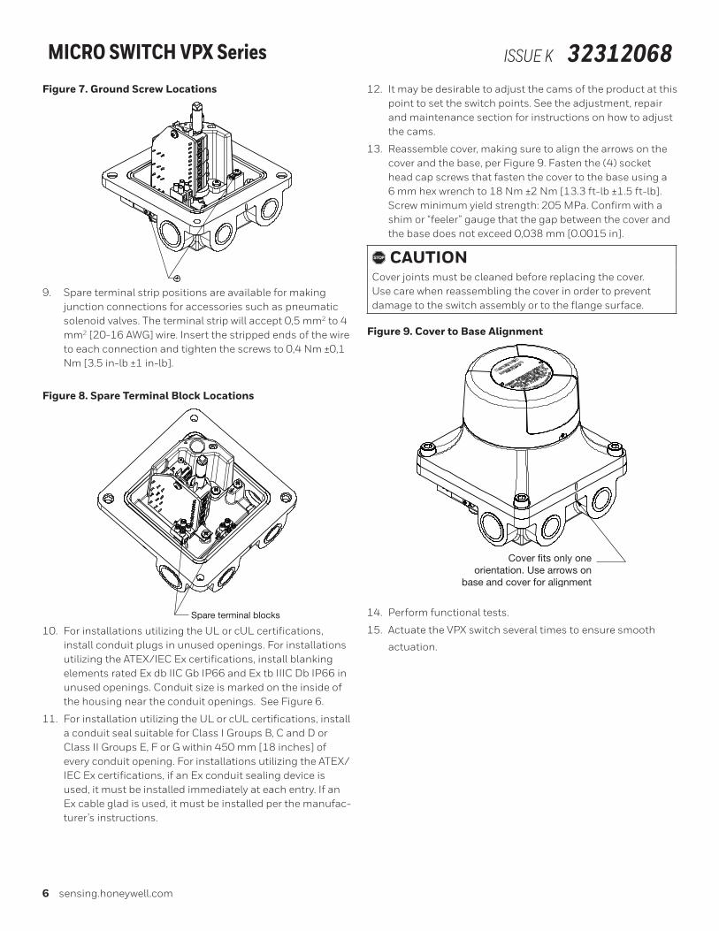
Figure 9. Cover to Base Alignment
Cover fits only oneorientation. Use arrows on
base and cover for alignment
14. Perform functional tests.
15. Actuate the VPX switch several times to ensure smooth
actuation.

Sensing and Internet of Things 7
MICRO SWITCH VPX Series ISSUE K 32312068VISUAL INDICATOR ADJUSTMENTThe visual indicator can be adjusted in two ways, either by rotat-ing the window through which the indicator is visible or actually repositioning the indicator to swap the OPEN and CLOSED positions.
To rotate the window, loosen the two set screws of the indicator cover (See Figure 10) by 1 turn each using a 2 mm hex wrench, rotate the cover and then tighten the set screws one turn again until the face of the set screw is flush to the cover. Tighten to 0,15 Nm [1.3 in-lb] max. Do not over tighten these screws as it may impact the ingress protection of this cover.
Figure 10. Indicator Cover Alignment
Set screws
Indicator cover rotated 90°
To reposition the indicator, loosen the two set screws of the in-dicator cover by 4 ½ turns using a 2 mm hex wrench and lift this cover off the VPX. Next, lift the indicator off and rotate it to the desired orientation and position it back in place. The indicator
is adjustable in 90° increments. Finally, reposition the indicator cover to the desired orientation and tighten the set screws by 4 ½ turns again until the face of the set screw is flush to the cover. Tighten to 0,15 Nm [1.3 in-lb] max. Do not over tighten these screws as it may impact the ingress protection of this cover.
Figure 11. Indicator Adjustment
Loosen set screws.Lift off cover.
Lift off indicator.Rotate todesired position.
CAM ADJUSTMENTThe switch points of each switch are factory set relative to the shaft position. See VPX Series Chart 1 drawing for these set points, as they vary by model. The switch points can be adjust-ed by repositioning the cams inside the product.
mWARNINGDO NOT OPEN the VPX when energized or in a flammable atmosphere
1. DO NOT OPEN the VPX when energized or a flammable atmosphere.
2. To access the cams, remove the (4) socket head cap screws that fasten the cover to the base using a 6 mm hex wrench.
3. Each cam mates with the shaft disc. Move cam axially to disengage teeth on wheel from teeth on shaft disc.

8 sensing.honeywell.com
MICRO SWITCH VPX Series ISSUE K 32312068Figure 12. Cam Adjustment
Shaft disc
Cam
4. Turn cam to desired position. Each notch on the shaft disk represents an operating point change of 4°. Arrows on the cam indicate the high point as a reference for alignment to the switch or to align one cam with another.
Figure 13. Cam Detail
Arrows on camindicate high point
5. In versions that use the snap action switches, you will hear an audible click with the switch actuates or releases.
6. When cam has been rotated to desired location, release cam to engage with mating shaft disc.
, CAUTIONDuring the cam adjustment it may be desirable to remove the spacer part (see Figure 14). Make sure to reassemble this piece after adjustment as it is a necessary part to ensure the maximum internal volume of the VPX meets agency requirements.
Figure 14. Spacer
Spacer
7. When cam adjustment is complete reassemble cover and torque the (4) socket head cap screws that fasten the cover to the base using a 6 mm hex wrench to 18 Nm ±2 Nm [13.3 ft-lb ±1.5 ft-lb].
SPECIAL CONDITIONS FOR SAFE USE• Aluminum enclosure - Care should be taken to minimize
the risk of ignition due to impact or friction.
• Potential electrostatic discharge - Clean product only with a damp cloth.
LEVER POSITIONINGVarious levers can be attached to the VPX products equipped with the knurled shaft option. See 7CX Series Chart 1, 2 and 3 drawings for a list of lever accessories. To install or reposition a lever, loosen the screw with a 9/64 inch hexagon key wrench, move the lever to the desired position and securely tighten the screw until the “teller tab” can no longer be moved by hand. Then tighten the screw another 1/8 to 1/4 turn to assure that the lever is tight on the shaft. Hexagon key wrenches are pro-vided in adjusting tool set LSZ4005 for this purpose.
Figure 15. Lever Adjustment
Teller tabLever lockingscrew

Sensing and Internet of Things 9
MICRO SWITCH VPX Series ISSUE K 32312068To order replacement levers, order the part number which is metal stamped on either the lever or the hub. Only non-sparking levers can be used to retain the explosion-proof properties.
ACCESSORIESA mounting bracket kit is available as an accessory, Honeywell part number VPZB1.
Figure 16. Accessory Bracket80,0[3.15]
30,0[1.18]
30,0[1.18]
130,0[5.12]
47 ±10[1.8 ±0.3] 47 ±10
[1.8 ±0.3]
In addition, conduit plugs are available in the following sizes:
Table 3. Conduit Plug Accessories
Size Honeywell Part Number Tightening Specification
1/2-14 NPT VPZPA Hand tight and then 1 to 2 full turns using a wrench
3/4-14 NPT VPZPB Hand tight and then 1 to 2 full turns using a wrench
M20 x 1.5 VPZPC Hand tight and then 1/4 to 1 full turn using a wrench
M25 x 1.5 VPZPD Hand tight and then 1/4 to 1 full turn using a wrench

10 sensing.honeywell.com
MICRO SWITCH VPX Series ISSUE K 32312068Figure 17. Mounting Dimensions
CLOSED
75 [3.0] min.to remove cover
95,8[3.77]
Ø 105,8[Ø 4.16]
52,0[2.05]
4,5[0.18]
2 X 32,5[1.28]
65,0 [2.56]
29,0[1.14]
140,0[5.51]
Conduit Position “C”
Conduit Position “D”
Conduit Position “B”
Conduit Position “A”
35,36[1.392]
140,0[5.51]
57,15[2.25]
57,15[2.25]
35,36[1.392]
4 X M6 x 1 8
4 X M8 x 1.25 8

Sensing and Internet of Things 11
MICRO SWITCH VPX Series ISSUE K 32312068

Warranty/RemedyHoneywell warrants goods of its manufacture as being free of defective materials and faulty workmanship during the applicable warranty period. Honeywell’s standard product warranty applies unless agreed to otherwise by Honeywell in writing; please refer to your order acknowledgement or consult your local sales office for specific warranty details. If warranted goods are returned to Honeywell during the period of coverage, Honeywell will repair or replace, at its option, without charge those items that Honeywell, in its sole discretion, finds defective. The foregoing is buyer’s sole remedy and is in lieu of all other warranties, expressed or implied, including those of merchantability and fitness for a particular purpose. In no event shall Honeywell be liable for consequential, special, or indirect damages.
While Honeywell may provide application assistance personally, through our literature and the Honeywell web site, it is buyer’s sole responsibility to determine the suitability of the product in the application.
Specifications may change without notice. The information we supply is believed to be accurate and reliable as of this writing. However, Honeywell assumes no responsibility for its use.
Honeywell serves its customers through a worldwide network of sales offices, representatives and distributors. For application assistance, current specifications, pricing or name of the nearest Authorized Distributor, contact your local sales office or:
E-mail: [email protected]: sensing.honeywell.comPhone and Fax: USA/Canada +1-800-537-6945International +1-815-235-6847; +1-815-235-6545 Fax
Honeywell Sensing and Internet of Things9680 Old Bailes Road
Fort Mill, SC 29707
honeywell.com32312068-K-EN | 10 | 11/18© 2017 Honeywell International Inc. All rights reserved.
MICRO SWITCH VPX Series ISSUE K 32312068
Honeywell Sensing and Controla division of Honeywell International Inc.11 West Spring StreetFreeport, IL 61032


