INSTALLATION INSTRUCTIONS FOR HORN KITS - … INSTRUCTIONS FOR HORN KITS ... (use mounting gasket...
2
INSTALLATION INSTRUCTIONS FOR HORN KITS ECR 5594 Rev E Filename: H15296.doc SOLENOID CLEANING PROCEDURE 1. Drain all air from tank. (Compressor to be turned OFF to prevent it from running due to pressure drops in the air tank). 2. Using 1/2" wrench, disconnect horn air line from solenoid by loosening 1/2" compression nut. 3. Using 3/4" wrench, loosen and remove brass outlet fitting that the air line was attached to. Removal of this fitting allows access to inside chamber of solenoid valve. 4. Slowly remove plunger and spring from inside of valve to permit cleaning. 5. Inspect metal surface of plunger and plunger housing for corrosion build-up and remove with 1000 grit wet/dry sand paper, steel wool, emery board, or similar product. After thoroughly cleaning plunger surface and plunger housing surface, inspect rubber tip. Tip should be relatively smooth to allow proper seating against the brass outlet fitting. 6. After cleaning and inspecting the plunger and plunger housing, reassemble the solenoid. Place the spring back into the hole in the plunger and re-insert plunger (Spring end first) into the solenoid. To check for proper placement, simply depress plunger with fingertip. Plunger should travel in and out the plunger housing smoothly. (Lubricate grease may be using to lubricate the spring). 7. Place brass outlet fitting back into position and tighten with 3/4" wrench. 8. Re-attach air line to the outlet of the solenoid and tighten compression nut. 9. Procedure is now complete. Next turn ON compressor and allow air tank to re-fill and your system will be back in full operation. 10. This procedure may have to be performed several times per year depending on horn use, climate, and/or horn mounting location. 11. If plunger and spring are not reusable, a replacement kit is available. Hadley part number is HPB550B All Hadley products carry a limited warranty for 12 months from date of purchase. We will repair or replace, at our option, defects in material and workmanship during that period when product and proof of purchase are returned to our service department at the address below. Hadley Attn: Service Department 2851 Prairie SW Grandville, MI 49418 Service Department: (616) 249-8462 www.hadleyadvantage.com Main: (616) 530-1717 Fax: (616) 530-3283 IMPORTANT: REVIEW ALL INSTRUCTIONS, PARTS LISTS, & INSTALLATION DIAGRAMS BEFORE STARTING INSTALLATION HORN ASSEMBLY 1. For best results, mount horns in an unobstructed opening for sound to carry straight ahead. If possible mount horn with slight downward angle to allow moisture to drain out. 2. For roof mount installation: If vehicle is equipped with interior roof trim panel, remove to install horns. 3. Drill (1) 1/2 in. and (2) 5/16 in. holes (use mounting pad for template, item# 3) in position desired for horn. 4. Place mounting pad between base of horn and top of vehicle roof. 5. Place tensions washer (item# 4) on mounting elbow (item# 7) as shown in Group I, next thread the elbow into the base of the horn from under the roof. Insert (2) screws (item# 1) through hole of horn base and roof, attach lock washer (item#5) and hex nut (item# 6). Connect nylon tubing (item# 10) to mounting elbow using brass insert (item# 8) and compression nut (item# 9). Then run tube down to tank location and replace interior roof trim panel. 6. For projector support installation: Slide the projector support (item# 12) toward the horn bell until grommet (item# 11) firmly contacts with horn projector body. Drill (2) 5/16 in holes (use mounting gasket for template, item# 13). Place gasket between projector support base and top of mounting surface. Insert (2) screws (item# 1) through hole of projector support base and mounting surface, attach lock washer (item # 5) and hex nut (item# 6). (See Group I for sample installation). TANK ASSEMBLY 1. Select mounting location for air tank (item# 25) keeping in mind the orientation of the tank and visibility of the pressure gauge (item# 21).Use thread sealant on all uncoated pipe threads components. (See Group II for sample installation) 2. Thread 2 brass fittings (item# 16) and check valve (item# 20) into brass cross (item# 18), then install the brass fitting into either one of the air tank outlet (item# 25). Next thread the solenoid threaded inlet (item# 15) into the brass fitting (item# 16). Thread the tire valve (item# 17) into remaining opening threaded hole in brass cross (item# 18). Connect nylon tubing (item# 10) to solenoid outlet using brass insert (item# 8) and compression nut (item# 9). (See group II for sample installation). 3. Thread brass tee fitting (item# 19) into the remaining tank outlet. Thread the pressure gauge (item# 21) and pressure switch (item# 22) into the tee. CAUTION: Tighten pressure switch and pressure gauge on brass hex body only. 4. To mount tank drill (2) 11/32 in. diameter holes spaced 4 in. apart in a rigid surface. Insert tank studs through the holes and secure with locknuts (item# 26). COMPRESSOR ASSEMBLY 1. As shown in group III, slide the (2) grommets (item# 31) into slots. Next push the (2) brass eyelets (item# 30) into the grommets. Pull the (4) bumpers (item# 33) through the (4) round holes on the bracket. 2. Clamp compressor head and install brass fitting (item#27) into air outlet as shown in group III. 3. Mount compressor on rigid support. Do not mount on fender well, firewall or other flexible material. Do locate compressor in area with good air flow and away from road surface to avoid excessive water and dirt conditions. 4. Mounting requires (2) holes spaced 2- 3/16 in. apart, each having a diameter of 7/32 in. 5. To mount compressor, insert #10-32 bolt (item# 29) through the brass eyelet and through the 7/32 in. hole. Secure with the #10-32 nut (item# 32) as shown in group III. Do not over tighten mounting bolts. 6. Connect nylon tubing from air outlet fitting (item# 27) to the check valve (item# 20) on the tank using brass inserts (item# 8) and compression nut (item# 9) as shown in Group II and Group III. ELECTRICAL ASSEMBLY 1. As shown in group III connect orange (+) wire from compressor motor to either pressure switch terminal using ¼” receptacle terminal (item# 23). Next, connect fuse holder (item#24) to the other pressure switch terminal. Install other end of fuse holder to "ignition activated" accessory terminal in fuse panel. Attach motor's black wire (-) to vehicle ground. 2. As shown in schematic wiring mount toggle switch (item#34) on or under the dash in a location easily accessible to the driver. Connect wire (item#35) from vehicle ground to either solenoid terminal (item# 15). Connect other solenoid terminal to either terminal on the toggle switch. Connect remaining toggle switch terminal in line with the existing horn wire using a wire splice connector (item#37). With toggle switch in "off" position, only the vehicles electric horn will operate. With switch in "on" position, air horns and electric horn will be operated. NOTE: Compressor starts automatically when pressure drops below 110 psi. If more than 4 minutes are required to pump tank to full pressure (110-135 psi) with engine running and compressor does not shut off, check all connections with soapy water or bubble solution for leaks. Use thread sealant on all uncoated pipe threads. Maximum cycle time 7 minutes with 30 minute cool down. CAUTION: Check local noise abatement ordinances to avoid legal violations.
-
Upload
nguyendung -
Category
Documents
-
view
224 -
download
1
Transcript of INSTALLATION INSTRUCTIONS FOR HORN KITS - … INSTRUCTIONS FOR HORN KITS ... (use mounting gasket...
INSTALLATION INSTRUCTIONS FOR HORN KITS
ECR 5594 Rev E Filename: H15296.doc
SOLENOID CLEANING PROCEDURE
1. Drain all air from tank. (Compressor to be turned OFF to prevent it from running due to pressure drops in the air tank).
2. Using 1/2" wrench, disconnect horn air line from solenoid by loosening 1/2" compression nut.
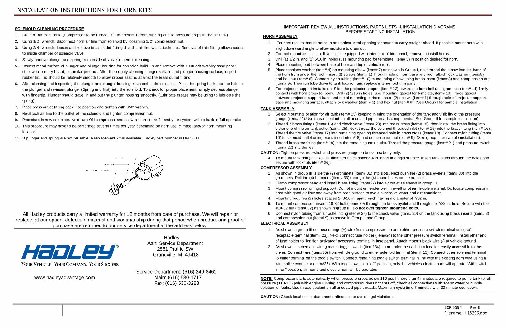
3. Using 3/4" wrench, loosen and remove brass outlet fitting that the air line was attached to. Removal of this fitting allows access to inside chamber of solenoid valve.
4. Slowly remove plunger and spring from inside of valve to permit cleaning.
5. Inspect metal surface of plunger and plunger housing for corrosion build-up and remove with 1000 grit wet/dry sand paper, steel wool, emery board, or similar product. After thoroughly cleaning plunger surface and plunger housing surface, inspect rubber tip. Tip should be relatively smooth to allow proper seating against the brass outlet fitting.
6. After cleaning and inspecting the plunger and plunger housing, reassemble the solenoid. Place the spring back into the hole in the plunger and re-insert plunger (Spring end first) into the solenoid. To check for proper placement, simply depress plunger with fingertip. Plunger should travel in and out the plunger housing smoothly. (Lubricate grease may be using to lubricate the spring).
7. Place brass outlet fitting back into position and tighten with 3/4" wrench.
8. Re-attach air line to the outlet of the solenoid and tighten compression nut.
9. Procedure is now complete. Next turn ON compressor and allow air tank to re-fill and your system will be back in full operation.
10. This procedure may have to be performed several times per year depending on horn use, climate, and/or horn mounting location.
11. If plunger and spring are not reusable, a replacement kit is available. Hadley part number is HPB550B
All Hadley products carry a limited warranty for 12 months from date of purchase. We will repair or
replace, at our option, defects in material and workmanship during that period when product and proof of purchase are returned to our service department at the address below.
Hadley
Attn: Service Department 2851 Prairie SW Grandville, MI 49418
Service Department: (616) 249-8462 www.hadleyadvantage.com Main: (616) 530-1717 Fax: (616) 530-3283
IMPORTANT: REVIEW ALL INSTRUCTIONS, PARTS LISTS, & INSTALLATION DIAGRAMS BEFORE STARTING INSTALLATION HORN ASSEMBLY
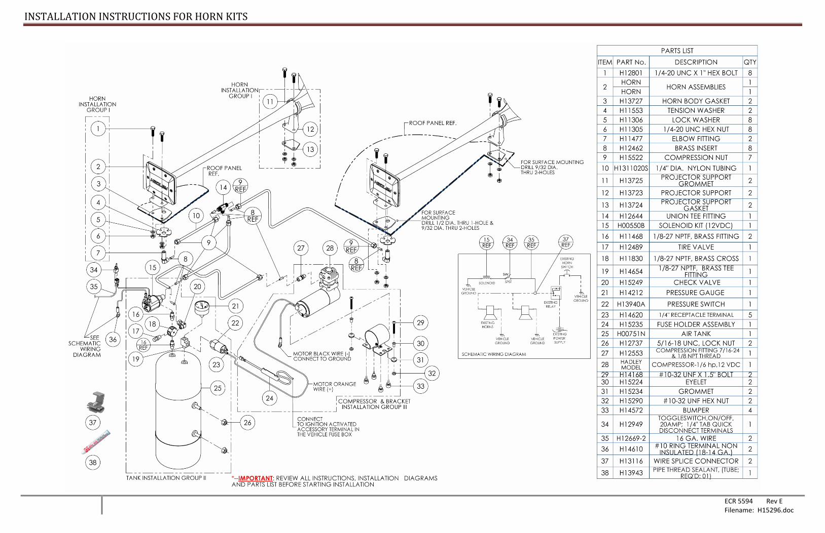
1. For best results, mount horns in an unobstructed opening for sound to carry straight ahead. If possible mount horn with slight downward angle to allow moisture to drain out.
2. For roof mount installation: If vehicle is equipped with interior roof trim panel, remove to install horns. 3. Drill (1) 1/2 in. and (2) 5/16 in. holes (use mounting pad for template, item# 3) in position desired for horn. 4. Place mounting pad between base of horn and top of vehicle roof. 5. Place tensions washer (item# 4) on mounting elbow (item# 7) as shown in Group I, next thread the elbow into the base of
the horn from under the roof. Insert (2) screws (item# 1) through hole of horn base and roof, attach lock washer (item#5) and hex nut (item# 6). Connect nylon tubing (item# 10) to mounting elbow using brass insert (item# 8) and compression nut (item# 9). Then run tube down to tank location and replace interior roof trim panel.
6. For projector support installation: Slide the projector support (item# 12) toward the horn bell until grommet (item# 11) firmly contacts with horn projector body. Drill (2) 5/16 in holes (use mounting gasket for template, item# 13). Place gasket between projector support base and top of mounting surface. Insert (2) screws (item# 1) through hole of projector support base and mounting surface, attach lock washer (item # 5) and hex nut (item# 6). (See Group I for sample installation).
TANK ASSEMBLY 1. Select mounting location for air tank (item# 25) keeping in mind the orientation of the tank and visibility of the pressure
gauge (item# 21).Use thread sealant on all uncoated pipe threads components. (See Group II for sample installation) 2. Thread 2 brass fittings (item# 16) and check valve (item# 20) into brass cross (item# 18), then install the brass fitting into
either one of the air tank outlet (item# 25). Next thread the solenoid threaded inlet (item# 15) into the brass fitting (item# 16). Thread the tire valve (item# 17) into remaining opening threaded hole in brass cross (item# 18). Connect nylon tubing (item# 10) to solenoid outlet using brass insert (item# 8) and compression nut (item# 9). (See group II for sample installation).
3. Thread brass tee fitting (item# 19) into the remaining tank outlet. Thread the pressure gauge (item# 21) and pressure switch (item# 22) into the tee.
CAUTION: Tighten pressure switch and pressure gauge on brass hex body only. 4. To mount tank drill (2) 11/32 in. diameter holes spaced 4 in. apart in a rigid surface. Insert tank studs through the holes and
secure with locknuts (item# 26). COMPRESSOR ASSEMBLY
1. As shown in group III, slide the (2) grommets (item# 31) into slots. Next push the (2) brass eyelets (item# 30) into the grommets. Pull the (4) bumpers (item# 33) through the (4) round holes on the bracket.
2. Clamp compressor head and install brass fitting (item#27) into air outlet as shown in group III. 3. Mount compressor on rigid support. Do not mount on fender well, firewall or other flexible material. Do locate compressor in
area with good air flow and away from road surface to avoid excessive water and dirt conditions. 4. Mounting requires (2) holes spaced 2- 3/16 in. apart, each having a diameter of 7/32 in. 5. To mount compressor, insert #10-32 bolt (item# 29) through the brass eyelet and through the 7/32 in. hole. Secure with the
#10-32 nut (item# 32) as shown in group III. Do not over tighten mounting bolts. 6. Connect nylon tubing from air outlet fitting (item# 27) to the check valve (item# 20) on the tank using brass inserts (item# 8)
and compression nut (item# 9) as shown in Group II and Group III. ELECTRICAL ASSEMBLY
1. As shown in group III connect orange (+) wire from compressor motor to either pressure switch terminal using ¼” receptacle terminal (item# 23). Next, connect fuse holder (item#24) to the other pressure switch terminal. Install other end of fuse holder to "ignition activated" accessory terminal in fuse panel. Attach motor's black wire (-) to vehicle ground.
2. As shown in schematic wiring mount toggle switch (item#34) on or under the dash in a location easily accessible to the driver. Connect wire (item#35) from vehicle ground to either solenoid terminal (item# 15). Connect other solenoid terminal to either terminal on the toggle switch. Connect remaining toggle switch terminal in line with the existing horn wire using a wire splice connector (item#37). With toggle switch in "off" position, only the vehicles electric horn will operate. With switch in "on"
position, air horns and electric horn will be operated.
NOTE: Compressor starts automatically when pressure drops below 110 psi. If more than 4 minutes are required to pump tank to full pressure (110-135 psi) with engine running and compressor does not shut off, check all connections with soapy water or bubble solution for leaks. Use thread sealant on all uncoated pipe threads. Maximum cycle time 7 minutes with 30 minute cool down. CAUTION: Check local noise abatement ordinances to avoid legal violations.
INSTALLATION INSTRUCTIONS FOR HORN KITS
ECR 5594 Rev E Filename: H15296.doc