Generic Quick Coupler Lock Kit Installation Instructions ...
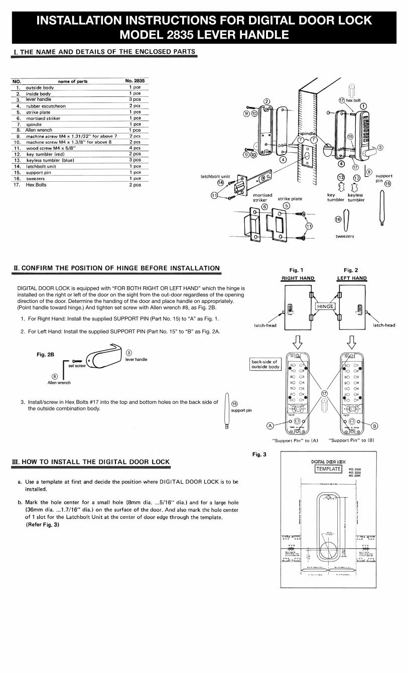
1. For Right Hand: Install the supplied SUPPORT PIN (Part No. 15) to “A” as Fig. 1.
2. For Left Hand: Install the supplied SUPPORT PIN (Part No. 15” to “B” as Fig. 2A.
3. Install/screw in Hex Bolts #17 into the top and bottom holes on the back side of the outside combination body.
INSTALLATION INSTRUCTIONS FOR DIGITAL DOOR LOCKMODEL 2835 LEVER HANDLE
lever handle 3 pcs
8. Allen wrench 1 pce
17. Hex Bolts 2 pcs
17 hex bolt
17
7 7
8
15
support pin
8
Fig. 2B
Allen wrench
3
lever handle
set screw
No. 2835
DIGITAL DOOR LOCK is equipped with “FOR BOTH RIGHT OR LEFT HAND” which the hinge is installed on the right or left of the door on the sight from the out-door regardless of the opening direction of the door. Determine the handing of the door and place handle on appropriately. (Point handle toward hinge.) And tighten set screw with Allen wrench #8, as Fig. 2B.
2 pcs3 pcs
15
17
3
NO. 2285
For door thickness from 1.5” up to 2.25” use full spindle #7
For door thickness for 1.125” to 1.75” cut spindle tab off.
Making sure the spindle is the correct length according to the door thickness (if spindle is too long it will cause the lock to bind, it is too short it will not engage the lock mechanism. Insert it into the spindle hole of the front body and through the spindle hole in the latch bolt from the inside of the door.
Break the spindle according to the door thickness.
spindle10:00 - 4:00 position
X off
cut line
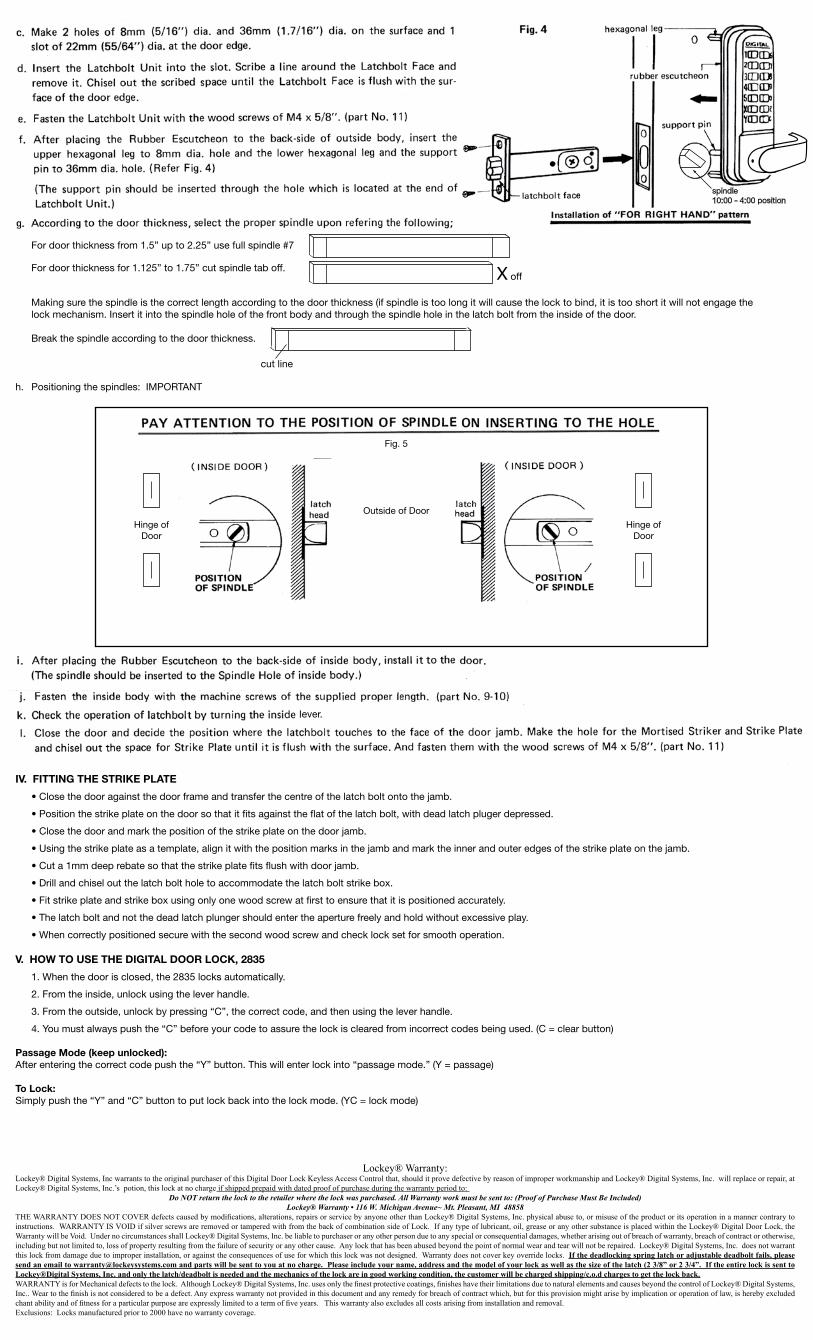
h. Positioning the spindles: IMPORTANT
Hinge of Door
Hinge of Door
lever.
IV. FITTING THE STRIKE PLATE
•Closethedooragainstthedoorframeandtransferthecentreofthelatchboltontothejamb.
•Positionthestrikeplateonthedoorsothatitfitsagainsttheflatofthelatchbolt,withdeadlatchplugerdepressed.
•Closethedoorandmarkthepositionofthestrikeplateonthedoorjamb.
•Usingthestrikeplateasatemplate,alignitwiththepositionmarksinthejambandmarktheinnerandouteredgesofthestrikeplateonthejamb.
•Cuta1mmdeeprebatesothatthestrikeplatefitsflushwithdoorjamb.
•Drillandchiseloutthelatchboltholetoaccommodatethelatchboltstrikebox.
•Fitstrikeplateandstrikeboxusingonlyonewoodscrewatfirsttoensurethatitispositionedaccurately.
•Thelatchboltandnotthedeadlatchplungershouldentertheaperturefreelyandholdwithoutexcessiveplay.
•Whencorrectlypositionedsecurewiththesecondwoodscrewandchecklocksetforsmoothoperation.
V. HOW TO USE THE DIGITAL DOOR LOCK, 2835
1.Whenthedoorisclosed,the2835locksautomatically.
2. From the inside, unlock using the lever handle.
3. From the outside, unlock by pressing “C”, the correct code, and then using the lever handle.
4. You must always push the “C” before your code to assure the lock is cleared from incorrect codes being used. (C = clear button)
Passage Mode (keep unlocked):After entering the correct code push the “Y” button. This will enter lock into “passage mode.” (Y = passage)
To Lock:Simply push the “Y” and “C” button to put lock back into the lock mode. (YC = lock mode)
Fig. 5
Outside of Door
Lockey® Warranty:Lockey® Digital Systems, Inc warrants to the original purchaser of this Digital Door Lock Keyless Access Control that, should it prove defective by reason of improper workmanship and Lockey® Digital Systems, Inc. will replace or repair, at Lockey® Digital Systems, Inc.’s potion, this lock at no charge if shipped prepaid with dated proof of purchase during the warranty period to:
Do NOT return the lock to the retailer where the lock was purchased. All Warranty work must be sent to: (Proof of Purchase Must Be Included)Lockey® Warranty • 116 W. Michigan Avenue~ Mt. Pleasant, MI 48858
THE WARRANTY DOES NOT COVER defects caused by modifications, alterations, repairs or service by anyone other than Lockey® Digital Systems, Inc. physical abuse to, or misuse of the product or its operation in a manner contrary to instructions. WARRANTY IS VOID if silver screws are removed or tampered with from the back of combination side of Lock. If any type of lubricant, oil, grease or any other substance is placed within the Lockey® Digital Door Lock, the Warranty will be Void. Under no circumstances shall Lockey® Digital Systems, Inc. be liable to purchaser or any other person due to any special or consequential damages, whether arising out of breach of warranty, breach of contract or otherwise, including but not limited to, loss of property resulting from the failure of security or any other cause. Any lock that has been abused beyond the point of normal wear and tear will not be repaired. Lockey® Digital Systems, Inc. does not warrant this lock from damage due to improper installation, or against the consequences of use for which this lock was not designed. Warranty does not cover key override locks. If the deadlocking spring latch or adjustable deadbolt fails, please send an email to [email protected] and parts will be sent to you at no charge. Please include your name, address and the model of your lock as well as the size of the latch (2 3/8” or 2 3/4”. If the entire lock is sent to Lockey®Digital Systems, Inc. and only the latch/deadbolt is needed and the mechanics of the lock are in good working condition, the customer will be charged shipping/c.o.d charges to get the lock back.WARRANTY is for Mechanical defects to the lock. Although Lockey® Digital Systems, Inc. uses only the finest protective coatings, finishes have their limitations due to natural elements and causes beyond the control of Lockey® Digital Systems, Inc.. Wear to the finish is not considered to be a defect. Any express warranty not provided in this document and any remedy for breach of contract which, but for this provision might arise by implication or operation of law, is hereby excluded chant ability and of fitness for a particular purpose are expressly limited to a term of five years. This warranty also excludes all costs arising from installation and removal. Exclusions: Locks manufactured prior to 2000 have no warranty coverage.