Installation Instructions - AlarmHow.net Express/Concord Express... · Bypassing ... System Alarm...
76
Document No. 466-1665 Rev. B Installation Instructions This document describes the installation, programming, test- ing, and troubleshooting procedures for installing Concord Express security systems. About This Manual ........................... 5 Special Installation Requirements ........................ 5 UL Listed Systems......................................... 5 UL-Canada Listed Systems ........................... 6 California State Fire Marshall Listed Systems ............................................... 6 Planning the Installation.................. 6 Standard Panel ...................................................... 6 Touchpads ............................................................. 6 SnapCards ............................................................. 7 Installing the System ....................... 7 Determine the Panel Location............................... 7 Total System Power and Wire Length Guidelines ............................................................. 8 Mounting the Panel ............................................... 9 Identify Panel Components ................................... 10 Connecting the Panel to Earth Ground ................. 10 Installing Optional SnapCards .............................. 10 Connecting Detection Devices to Panel Zone Inputs ........................................................... 11 Connecting Intrusion Detection Devices ....... 11 Connecting 2-Wire Smoke Detectors ............ 12 Connecting 4-Wire Smoke Detectors ............ 12 Connecting Sirens ................................................. 13 Hardwire Interior Siren (13-374) ................... 13 Hardwire Siren (13-046) ................................ 14 Interior Piezo Siren (30-006) ......................... 14 Connecting Siren Drivers, Self Contained Sirens, Bells .......................................................... 14 Connecting Touchpads ......................................... 15 Installing an RJ-31X Phone Jack (13-081) ........... 15 Connecting the Phone Line to the Panel with a DB-8 Cord .................................................. 17 Connecting the AC Power Transformer (60-822) 17 Powering Up the Panel ......................................... 17 Programming the Panel ................... 18 Entering Programming Mode ............................... 18 Touchpad Button Programming Functions ........... 19 Moving Through Program Mode Tiers and Menus ............................................................. 19 Programming Tier 1 Menu Items.......................... 20 Programming Tier 2 Menu Items ..........................20 Using Shortcut Numbers................................21 Security Menu ................................................ 21 Phones Menu..................................................24 Phone Options Menu .....................................27 Timers Menu ..................................................30 Touchpad Options Menu ............................... 32 Reporting Menu ............................................. 33 Siren Options Menu .......................................38 Sensors Menu.................................................39 Accessory Modules Menu .............................41 Onboard Options Menu .................................43 Exiting Programming Mode.................................. 44 Entering User Programming Mode .......................44 Time and Date Menu .....................................44 User Codes Menu...........................................45 Options Menu ................................................ 46 System Version Menu....................................47 Downloader Programming ....................................47 ToolBox Downloader Programming .................................................47 Testing the System .......................... 48 Basic System Commands ...................................... 48 Testing Zones/Sensors ..........................................48 If a Wireless Sensor Does Not Test ...............49 Testing Phone Communication .............................49 Testing Central Station/Pager Communication.....49 Testing Outputs/Sirens ..........................................50 Changing Fixed English LCD Touchpad Chime and Trouble Beep Tones .......................................50 Troubleshooting .............................. 51 Table T1. Panel Power ..........................................52 Table T2. Access Codes ........................................53 Table T3. Arming and Disarming .........................54 Table T4. Bypassing ............................................. 54 Table T5. Wireless Sensor and Touchpad Batteries................................................ 55 Table T6. Central Station/Pager Reporting ...........55 Table T7. Alphanumeric Touchpads..................... 56 Table T8. Sirens .................................................... 56 Table T9. Hardwire Zones ....................................57 Table T10. Wireless Sensor Zones .......................58
Transcript of Installation Instructions - AlarmHow.net Express/Concord Express... · Bypassing ... System Alarm...
Document No. 466-1665 Rev. BInstallation Instructions
This document describes the installation, programming, test-ing, and troubleshooting procedures for installing Concord Express security systems.
88
0
3
8
About This Manual ........................... 5Special Installation Requirements ........................5
UL Listed Systems.........................................5UL-Canada Listed Systems ...........................6California State Fire MarshallListed Systems...............................................6
Planning the Installation.................. 6Standard Panel ......................................................6Touchpads.............................................................6SnapCards .............................................................7
Installing the System....................... 7Determine the Panel Location...............................7Total System Power and Wire LengthGuidelines .............................................................8Mounting the Panel ...............................................9Identify Panel Components...................................10Connecting the Panel to Earth Ground .................10Installing Optional SnapCards ..............................10Connecting Detection Devices to PanelZone Inputs ...........................................................11
Connecting Intrusion Detection Devices.......11Connecting 2-Wire Smoke Detectors ............12Connecting 4-Wire Smoke Detectors ............12
Connecting Sirens .................................................13Hardwire Interior Siren (13-374)...................13Hardwire Siren (13-046)................................14Interior Piezo Siren (30-006) .........................14
Connecting Siren Drivers, Self ContainedSirens, Bells ..........................................................14Connecting Touchpads .........................................15Installing an RJ-31X Phone Jack (13-081) ...........15Connecting the Phone Line to the Panelwith a DB-8 Cord..................................................17Connecting the AC Power Transformer (60-822) 17Powering Up the Panel .........................................17
Programming the Panel ................... 18Entering Programming Mode ...............................18Touchpad Button Programming Functions...........19Moving Through Program Mode Tiersand Menus.............................................................19Programming Tier 1 Menu Items..........................20
Programming Tier 2 Menu Items..........................20Using Shortcut Numbers................................21Security Menu................................................21Phones Menu..................................................24Phone Options Menu .....................................27Timers Menu..................................................30Touchpad Options Menu ...............................32Reporting Menu .............................................33Siren Options Menu.......................................38Sensors Menu.................................................39Accessory Modules Menu .............................41Onboard Options Menu .................................43
Exiting Programming Mode..................................44Entering User Programming Mode.......................44
Time and Date Menu .....................................44User Codes Menu...........................................45Options Menu ................................................46System Version Menu....................................47
Downloader Programming....................................47ToolBox DownloaderProgramming .................................................47
Testing the System .......................... 48Basic System Commands......................................4Testing Zones/Sensors ..........................................4
If a Wireless Sensor Does Not Test ...............49Testing Phone Communication.............................49Testing Central Station/Pager Communication.....49Testing Outputs/Sirens..........................................50Changing Fixed English LCD Touchpad Chimeand Trouble Beep Tones .......................................5
Troubleshooting .............................. 51Table T1. Panel Power ..........................................52Table T2. Access Codes........................................5Table T3. Arming and Disarming .........................54Table T4. Bypassing .............................................54Table T5. Wireless Sensor and Touchpad
Batteries................................................55Table T6. Central Station/Pager Reporting...........55Table T7. Alphanumeric Touchpads.....................56Table T8. Sirens ....................................................56Table T9. Hardwire Zones ....................................57Table T10. Wireless Sensor Zones .......................5
1
7
Table T11. Wireless Touchpads............................59Table T12. Phones.................................................59Table T13. Downloader ........................................60
Appendix A: System PlanningWorksheets ...................................... 61
Programming Mode Menus andSettings ............................................ 71
System Wiring Diagram ........Back Page
List of FiguresFigure 1. Determining Panel Location.................. 7Figure 2. Mounting the Cabinet ............................ 9Figure 3. Installing the Antenna Housing ............. 9Figure 4. Installing the Circuit Board ................... 9Figure 5. Main Component Locations .................. 10Figure 6. Connecting the Panel to Earth Ground .. 10Figure 7. Installing a SnapCard onto thePanel’s SnapCard Header...................................... 11Figure 8. Connecting N/C and N/O IntrusionDetection Circuits ................................................. 11Figure 9. Connecting a PIR Motion Detector ....... 11Figure 10. Connecting 2-Wire Smoke Detectors .. 12Figure 11. Connecting 4-Wire Smoke Detectors .. 13Figure 12. Connecting Hardwire InteriorSiren 13-374.......................................................... 13Figure 13. Connecting Hardwire Siren 13-046..... 14Figure 14. Connecting an Interior Piezo Siren...... 14Figure 15. Connecting 2x16 Alphanumeric andFixed English LCD Touchpads ............................15Figure 16. Connecting 2x20 LCD/VFD Touchpads 15Figure 17. Installing an RJ-31X Phone Jack......... 16Figure 18. Connecting the DB-8 Cord to thePanel and RJ-31X Jack ......................................... 17Figure 19. Connecting a Power Transformer........ 17Figure 20. Connecting the Backup Battery........... 18Figure 21. Connecting a Programming Touchpad 18Figure 22. Tier 1 Programming Menus................. 19Figure 23. Tier 2 Programming Menus ................ 19Figure 24. Tier 2 Programming Menus ................ 20
List of TablesTable 1. Panel Voltage/Current Output Ranges.... 8Table 2. Maximum/Standby Device Current Draw8Table 3. Maximum Device Wire Lengths............. 8Table 4. Alphanumeric Touchpad ButtonProgramming Functions........................................ 19Table 5. Basic System Commands........................ 48Table 6. Pager System Event Codes ..................... 49Table 7. Pager Sensor/Zone and UserNumber Codes.......................................................50Table 8. System Alarm Sounds ............................50Table A1. System Hardwire Devices ...................59Table A2. Zone/Sensor Assignments ...................59Table A3. Sensor Group Characteristics ..............60
Table A4. Sensor Text/Item Numbers ................. 62Table A5. System Settings .................................. 63Table A6. System Event Trigger Numbers ......... 65Table A7. Sensor Group Event Trigger Numbers 65Table A8. Sensor Number Event Trigger
Numbers ............................................. 66Table A9. System Feature Event Trigger
Numbers ............................................. 66Table A10. Response Numbers ........................... 6
2
d
d
o
nt
Notices
FCC Notices
This equipment has been tested and found to comply with the limits for a class B digital device, pursuant to part 15 of the FCC rules. These limits are designed to provide
reasonable protection against harmful interference in a residential installation. This equipment generates, uses, and can radiate radio frequency energy and, if not installed an
used in accordance with the instructions, may cause harmful interference to radio communications. However, there is no guarantee that interference will not occur in a particular
installation. If this equipment does cause harmful interference to radio or television reception, which can be determined by turning the equipment off and on, the user is en-
couraged to try to correct the interference by one or more of the following measures:
• Install a quality radio or television outdoor antenna if the indoor antenna is not adequate.
• Reorient or relocate the panel.
• Move the panel away from the affected equipment.
• Move the panel away from any wire runs to the affected equipment.
• Connect the affected equipment and the panel to separate outlets, on different branch circuits.
• Consult the dealer or an experienced radio/TV technician for help.
• Send for the FCC booklet How to Identify and Resolve Radio-TV Interference Problems, available from the U.S. Government Printing Office, Washington, D.C.
20402. Stock Number: 004-000-00345-4.
Changes or modifications not expressly approved by Interactive Technologies, Inc. can void the user’s authority to operate the equipment.
This equipment complies with part 68 of the FCC rules. On the FCC label affixed to this equipment is the FCC Registration Number and Ringer Equivalence Number (REN)
for this equipment. If requested, provide this information to your telephone company.
The REN is used to calculate the maximum number of devices your telephone line will support with ringing service. In most areas the sum of all device RENs should not
exceed 5.0. Contact your local telephone company to determine the maximum REN for your calling area.
If your telephone equipment causes harm to the telephone network, your telephone company may temporarily disconnect your service. If possible, you will be notified in
advance. When advance notice is not practical, you will be notified as soon as possible. You will also be advised of your right to file a complaint with the FCC.
Your telephone company may make changes in its facilities, equipment, operations, or procedures that could affect the proper operation of your equipment. You will be given
advanced notice in order to maintain uninterrupted service.
If you experience trouble with this equipment, please contact
Interactive Technologies, Inc.2266 Second Street NorthNorth Saint Paul, MN 551091-800-777-1415
for service and repair information. The telephone company may ask you to disconnect this equipment from the network until the problem has been corrected or until you are
sure that the equipment is not malfunctioning.
This equipment may not be used on coin service provided by the telephone company. Connection to party lines is subject to state tariffs.
Declaration of Conformity (DoC)
Interactive Technologies, Inc. declares that the ITI model no. 60-806-95R is in conformity with Part 15 of the FCC Rules. Operation of this product is subject to the following
two conditions: (1) This device may not cause harmful interference, and (2) this device must accept any interference received, including interference that may cause undesire
operation.
Industry Canada Warnings
Notice:The Industry Canada Label identifies certified equipment. This certification means that the equipment meets telecommunications network protective, operational, and safety
requirements as prescribed in the appropriate Terminal Equipment Technical Requirement document(s). The Department does not guarantee the equipment will operate to the
user’s satisfaction.
Before installing this equipment, users should ensure that it is permissible to be connected to the facilities of the local telecommunications company. The equipment must als
be installed using an acceptable method of connection. The customer should be aware that compliance with the above conditions may not prevent degradation of service in
some situations.
Repairs to certified equipment should be coordinated by a representative designated by the supplier. Any repairs or alterations made by the user to this equipment, or equipme
malfunctions, may give the telecommunications company cause to request the user to disconnect the equipment.
Users should ensure for their own protection that the electrical ground connections of the power utility, telephone lines, and internal metallic water pipe system, if present, are
connected together. This precaution may be particularly important in rural areas.
Caution: Users should not attempt to make such connections themselves, but should contact the appropriate electric inspection authority, or electrician, as appropriate.
Notice:The Ringer Equivalence Number (REN) assigned to each terminal device provides an indication of the maximum number of terminals allowed to be connected to a telephone
interface. The termination on an interface may consist of any combination of devices subject only to the requirement that the sum of the Ringer Equivalence Number of all the
devices does not exceed 5.

s
t
e
,
-
AVIS D’INDUSTRIE CANADA
AVIS:
L’étiquette d’Industrie Canada identifie le matériel homologué. Cette étiquette certifie que le matériel est conforme aux normes de protection, d’ exploitation et de sécurité de
réseaux de télécommunications, comme le prescrivent les documents concernant les exigences techniques relatives au matérial terminal. Le Ministere n’assure toutefois pas
que le matériel fonctionnera à la satisfaction de l’utilisateur.
Avant d’installer ce matériel, l’utilisateur doit s’assurer qu’il est permis de le raccorder aux installations de l’enterprise locale de télécommunication. Le matériel doit égalemen
être installé en suivant une méthode acceptée de raccordement. L’abonné ne doit pas oublier qu’il est possible que la conformité aux conditions énoncées ci-dessus n’empêch
pas le dégradation du service dans certaines situations.
Les réparations de matériel homologué doivent être coordonnées par un représentant désigné par le fournisseur. L’entreprise de télécommunications peut demander à l’utili-
sateur de débrancher un appareil à la suite de réparations ou de modifications effectuées par l’utilisateur ou à cause de mauvais fonctionnement.
Pour sa propre protection, l’utilisateur doit s’assurer que tous les fils de mise à la terre de la source d’énergie électrique, des lignes téléphoniques et des canalisations d’eau
métalliques, s’il y en a, sont raccordés ensemble. Cette précaution est particulièrement importante dans les régions rurales.
Avertissment: L’utilisateur ne doit pas tenter de faire ces raccordements lui-meme; il doit avoir recours à un service d’inspection des installations électriques, ou à électricien
selon le cas.
AVIS:
L’indice d’équivalence de la sonnerie (IES) assigné à chaque dispositif terminal indique le nombre maximal de terminaux qui peuvent être raccordés à une interface. La ter
minaison d’une interface téléphonique peut consister en une combinaison de quelques dispositifs, à la seule condition que la somme d’indices d’équivalence de la sonnerie de
tous les dispositifs n’excède pas 5.
Trademarks
ITI, SuperBus, and ITI ToolBox are registered trademarks of Interactive Technologies, Inc. Concord and SnapCard are trademarks of Interactive Technologies, Inc. X-10 is a
registered trademark of X-10 (USA), Inc.
This manual may refer to products that are announced but are not yet available.
6 5 1 / 7 7 7 - 2 6 9 0
6 5 1 / 7 7 9 - 4 8 9 0
-
,
5-
ll
al g
About This Manual
This manual provides information for planning, in-stalling, programming, and testing this security sys-tem. When necessary, this manual refers you to other documentation included with compatible devices.
Planning sheets are included for you to record hard-ware layout and software programming settings.
Special Installation Require-ments
This security system can be used as a fire warning system, an intrusion alarm system, an emergency no-tification system, or any combination of the three.
Some installations may require configurations dictat-ed by city/state codes, insurance, or Underwriter’s Laboratories (UL). This section describes the various component and configuration listings.
UL Listed Systems
This section describes the requirements for UL Listed systems.
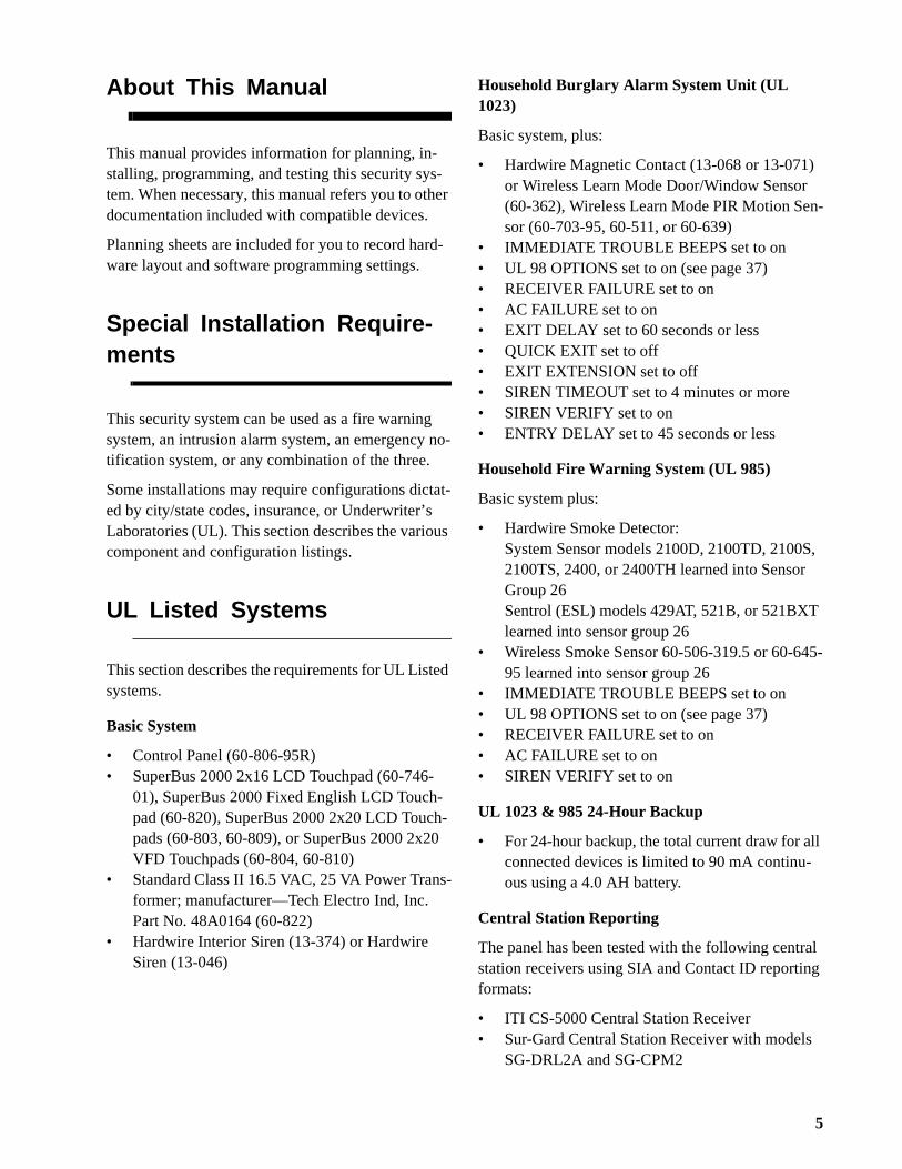
Basic System
• Control Panel (60-806-95R)• SuperBus 2000 2x16 LCD Touchpad (60-746-
01), SuperBus 2000 Fixed English LCD Touch-pad (60-820), SuperBus 2000 2x20 LCD Touch-pads (60-803, 60-809), or SuperBus 2000 2x20 VFD Touchpads (60-804, 60-810)
• Standard Class II 16.5 VAC, 25 VA Power Trans-former; manufacturer—Tech Electro Ind, Inc. Part No. 48A0164 (60-822)
• Hardwire Interior Siren (13-374) or Hardwire Siren (13-046)
Household Burglary Alarm System Unit (UL 1023)
Basic system, plus:
• Hardwire Magnetic Contact (13-068 or 13-071)or Wireless Learn Mode Door/Window Sensor (60-362), Wireless Learn Mode PIR Motion Sensor (60-703-95, 60-511, or 60-639)
• IMMEDIATE TROUBLE BEEPS set to on• UL 98 OPTIONS set to on (see page 37)• RECEIVER FAILURE set to on• AC FAILURE set to on• EXIT DELAY set to 60 seconds or less• QUICK EXIT set to off• EXIT EXTENSION set to off• SIREN TIMEOUT set to 4 minutes or more• SIREN VERIFY set to on• ENTRY DELAY set to 45 seconds or less
Household Fire Warning System (UL 985)
Basic system plus:
• Hardwire Smoke Detector:System Sensor models 2100D, 2100TD, 2100S2100TS, 2400, or 2400TH learned into SensorGroup 26Sentrol (ESL) models 429AT, 521B, or 521BXTlearned into sensor group 26
• Wireless Smoke Sensor 60-506-319.5 or 60-6495 learned into sensor group 26
• IMMEDIATE TROUBLE BEEPS set to on• UL 98 OPTIONS set to on (see page 37)• RECEIVER FAILURE set to on• AC FAILURE set to on• SIREN VERIFY set to on
UL 1023 & 985 24-Hour Backup
• For 24-hour backup, the total current draw for aconnected devices is limited to 90 mA continu-ous using a 4.0 AH battery.
Central Station Reporting
The panel has been tested with the following centrstation receivers using SIA and Contact ID reportinformats:
• ITI CS-5000 Central Station Receiver• Sur-Gard Central Station Receiver with models
SG-DRL2A and SG-CPM2
5
Planning the Installation
n n.
t s,
-
ts.
in .
t n.
-
UL-Canada Listed Systems
This section describes the requirements for ULC (UL Canada) Listed systems.
CSA Certified Accessories
Residential Burglary Alarm System Unit(ULC-S309)
Same as “UL Basic System and Household Burglary Alarm System Unit (UL 1023)” as described on pre-vious page.
Residential Fire Warning System Control Unit (ULC-S545-M89)
Same as “UL Basic System and Household Fire Warning System (UL 985)” as described on previous page.
NoteFor 24-hour backup, external power drain is limited to 90 mA continuous using a 4.0AH battery.
California State Fire Marshall Listed Systems
Same as Household Fire Warning System (UL 985), plus:
• SMOKE VERIFY must be set to off
Planning the Installation
This section describes the systems’s capabilities tohelp you get familiar with the system. Appendix A provides planning sheets with tables that let you record the hardware and programming configuratioof the system, to help prepare for system installatio
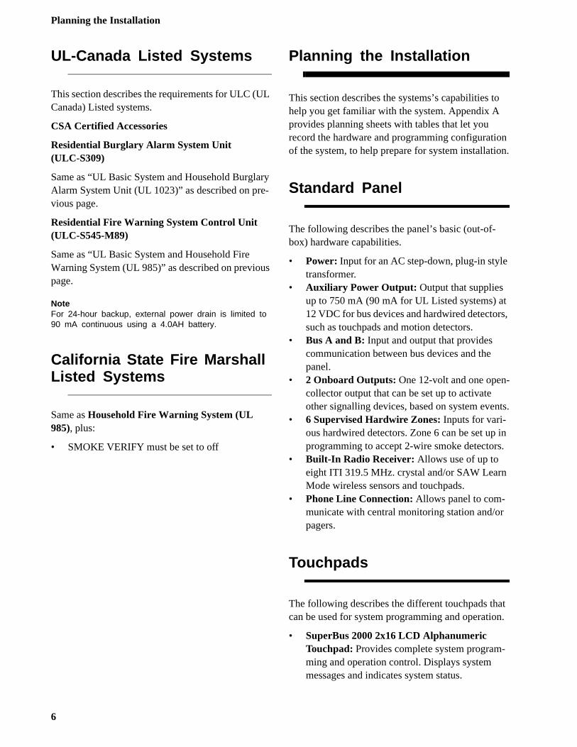
Standard Panel
The following describes the panel’s basic (out-of-box) hardware capabilities.
• Power: Input for an AC step-down, plug-in styletransformer.
• Auxiliary Power Output: Output that supplies up to 750 mA (90 mA for UL Listed systems) a12 VDC for bus devices and hardwired detectorsuch as touchpads and motion detectors.
• Bus A and B: Input and output that provides communication between bus devices and the panel.
• 2 Onboard Outputs: One 12-volt and one opencollector output that can be set up to activate other signalling devices, based on system even
• 6 Supervised Hardwire Zones: Inputs for vari-ous hardwired detectors. Zone 6 can be set upprogramming to accept 2-wire smoke detectors
• Built-In Radio Receiver: Allows use of up to eight ITI 319.5 MHz. crystal and/or SAW LearnMode wireless sensors and touchpads.
• Phone Line Connection: Allows panel to com-municate with central monitoring station and/orpagers.
Touchpads
The following describes the different touchpads thacan be used for system programming and operatio
• SuperBus 2000 2x16 LCD Alphanumeric Touchpad: Provides complete system programming and operation control. Displays system messages and indicates system status.
6
Installing the System
-
t -
r -
t
• SuperBus 2000 2x20 LCD/VFD Alphanu-meric Touchpads: Provide complete system programming and operation control, display sys-tem messages and indicate system status.
• SuperBus 2000 Fixed English LCD Touchpad: Provides operation control and user-program-ming access (not installer/dealer programming). Displays system messages and indicates systemstatus.
SnapCards
The following SnapCards expand the system as de-scribed:
• 8Z Input SnapCard: Provides eight additional hardwire zone inputs, of which two are dedicated for using 2-wire smoke detectors.
• 4 Output SnapCard: Provides four form C relay outputs that can be set up to activate other signalling devices, based on system events.
• 4Z Input/2 Output Combo SnapCard: Pro-vides three standard hardwire zone inputs, one 2-wire smoke detector loop input, and two outputs that can be set up to activate other signalling devices, based on system events.
Installing the System
This section describes how to install the system con-trol panel. Before starting the installation, plan your system layout and programming using the worksheets provided in Appendix A.
Installing the system consists of the following:
• Determining the Panel Location• Total System Power and Wire Length Guidelines• Mounting the Panel• Identifying Panel Main Components• Installing Optional SnapCards• Connecting Detection Devices to Panel Zone
Inputs• Connecting Sirens• Connecting Alphanumeric Touchpads• Installing an RJ-31X Phone Jack
• Connecting the Phone Line to the Panel with aDB-8 Cord
• Connecting the AC Power Transformer• Powering Up the Panel
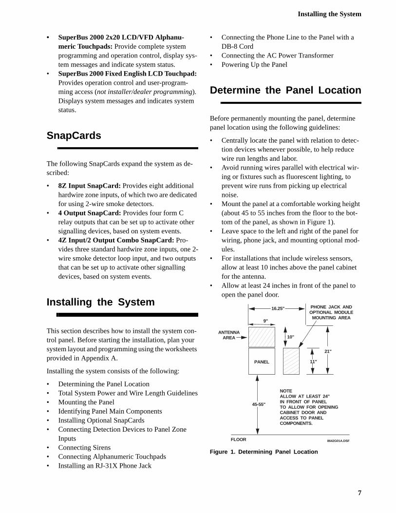
Determine the Panel Location
Before permanently mounting the panel, determinepanel location using the following guidelines:
• Centrally locate the panel with relation to detection devices whenever possible, to help reducewire run lengths and labor.
• Avoid running wires parallel with electrical wir-ing or fixtures such as fluorescent lighting, to prevent wire runs from picking up electrical noise.
• Mount the panel at a comfortable working heigh(about 45 to 55 inches from the floor to the bottom of the panel, as shown in Figure 1).
• Leave space to the left and right of the panel fowiring, phone jack, and mounting optional modules.
• For installations that include wireless sensors, allow at least 10 inches above the panel cabinefor the antenna.
• Allow at least 24 inches in front of the panel to open the panel door.
Figure 1. Determining Panel Location
PANEL
16.25"
9"
11"
21"
45-55"
PHONE JACK ANDOPTIONAL MODULE
MOUNTING AREA
ANTENNAAREA
NOTEALLOW AT LEAST 24"IN FRONT OF PANELTO ALLOW FOR OPENINGCABINET DOOR ANDACCESS TO PANELCOMPONENTS.
FLOOR 8642G01A.DSF
10"
7
Installing the System
ic-es .
d
Total System Power and Wire Length Guidelines
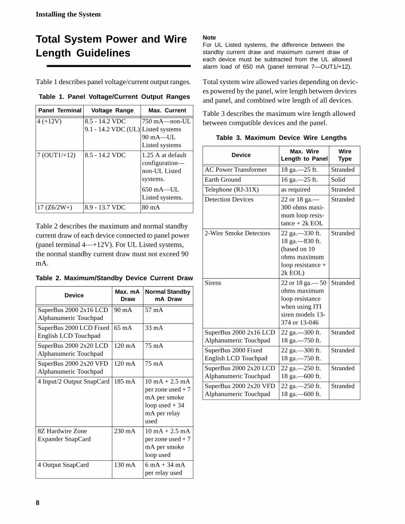
Table 1 describes panel voltage/current output ranges.
Table 2 describes the maximum and normal standby current draw of each device connected to panel power (panel terminal 4—+12V). For UL Listed systems, the normal standby current draw must not exceed 90 mA.
NoteFor UL Listed systems, the difference between the standby current draw and maximum current draw of each device must be subtracted from the UL allowed alarm load of 650 mA (panel terminal 7—OUT1/+12).
Total system wire allowed varies depending on deves powered by the panel, wire length between devicand panel, and combined wire length of all devices
Table 3 describes the maximum wire length allowebetween compatible devices and the panel.
Table 1. Panel Voltage/Current Output Ranges
Panel Terminal Voltage Range Max. Current
4 (+12V) 8.5 - 14.2 VDC9.1 - 14.2 VDC (UL)
750 mA—non-UL Listed systems90 mA—UL Listed systems
7 (OUT1/+12) 8.5 - 14.2 VDC 1.25 A at default configuration—non-UL Listed systems.
650 mA—UL Listed systems.
17 (Z6/2W+) 8.9 - 13.7 VDC 80 mA
Table 2. Maximum/Standby Device Current Draw
DeviceMax. mA
DrawNormal Standby
mA Draw
SuperBus 2000 2x16 LCD Alphanumeric Touchpad
90 mA 57 mA
SuperBus 2000 LCD Fixed English LCD Touchpad
65 mA 33 mA
SuperBus 2000 2x20 LCD Alphanumeric Touchpad
120 mA 75 mA
SuperBus 2000 2x20 VFD Alphanumeric Touchpad
120 mA 75 mA
4 Input/2 Output SnapCard 185 mA 10 mA + 2.5 mA per zone used + 7 mA per smoke loop used + 34 mA per relay used
8Z Hardwire Zone Expander SnapCard
230 mA 10 mA + 2.5 mA per zone used + 7 mA per smoke loop used
4 Output SnapCard 130 mA 6 mA + 34 mA per relay used
Table 3. Maximum Device Wire Lengths
DeviceMax. Wire
Length to PanelWire Type
AC Power Transformer 18 ga.—25 ft. Stranded
Earth Ground 16 ga.—25 ft. Solid
Telephone (RJ-31X) as required Stranded
Detection Devices 22 or 18 ga.—300 ohms maxi-mum loop resis-tance + 2k EOL
Stranded
2-Wire Smoke Detectors 22 ga.—330 ft.18 ga.—830 ft.(based on 10 ohms maximum loop resistance + 2k EOL)
Stranded
Sirens 22 or 18 ga.— 50 ohms maximum loop resistance when using ITI siren models 13-374 or 13-046
Stranded
SuperBus 2000 2x16 LCD Alphanumeric Touchpad
22 ga.—300 ft.18 ga.—750 ft.
Stranded
SuperBus 2000 Fixed English LCD Touchpad
22 ga.—300 ft.18 ga.—750 ft.
Stranded
SuperBus 2000 2x20 LCD Alphanumeric Touchpad
22 ga.—250 ft.18 ga.—600 ft.
Stranded
SuperBus 2000 2x20 VFD Alphanumeric Touchpad
22 ga.—250 ft.18 ga.—600 ft.
Stranded
8
Installing the System
l)
g -
Mounting the Panel
Use the following procedure to mount the panel to the wall or wall studs.
CautionMake sure you are free of static electricity whenever you work on the panel with the cover open. To discharge any static, first touch the metal panel chassis, then stay in contact with the chassis when touching the circuit board. Using an approved grounding strap is recom-mended.
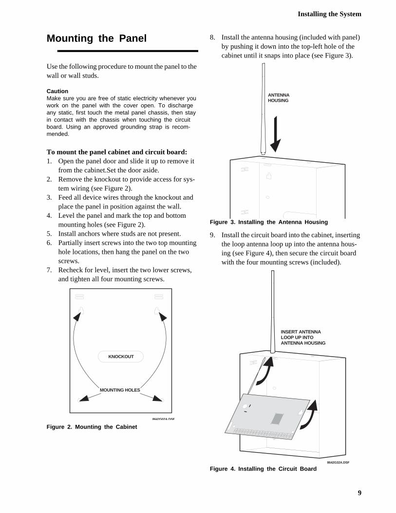
To mount the panel cabinet and circuit board:1. Open the panel door and slide it up to remove it
from the cabinet.Set the door aside.2. Remove the knockout to provide access for sys-
tem wiring (see Figure 2).3. Feed all device wires through the knockout and
place the panel in position against the wall.4. Level the panel and mark the top and bottom
mounting holes (see Figure 2).5. Install anchors where studs are not present.6. Partially insert screws into the two top mounting
hole locations, then hang the panel on the two screws.
7. Recheck for level, insert the two lower screws, and tighten all four mounting screws.
Figure 2. Mounting the Cabinet
8. Install the antenna housing (included with paneby pushing it down into the top-left hole of the cabinet until it snaps into place (see Figure 3).
Figure 3. Installing the Antenna Housing
9. Install the circuit board into the cabinet, insertinthe loop antenna loop up into the antenna housing (see Figure 4), then secure the circuit boardwith the four mounting screws (included).
Figure 4. Installing the Circuit Board
8642G02A.DSF
KNOCKOUT
MOUNTING HOLES
ANTENNAHOUSING
8642G32A.DSF
INSERT ANTENNA LOOP UP INTO ANTENNA HOUSING
9
Installing the System
ls:
-s,
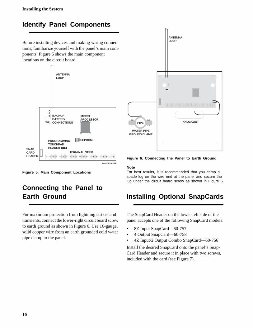
Identify Panel Components
Before installing devices and making wiring connec-tions, familiarize yourself with the panel’s main com-ponents. Figure 5 shows the main component locations on the circuit board.
Figure 5. Main Component Locations
Connecting the Panel to Earth Ground
For maximum protection from lightning strikes and transients, connect the lower-right circuit board screw to earth ground as shown in Figure 6. Use 16-gauge, solid copper wire from an earth grounded cold water pipe clamp to the panel.
Figure 6. Connecting the Panel to Earth Ground
NoteFor best results, it is recommended that you crimp a spade lug on the wire end at the panel and secure the lug under the circuit board screw as shown in Figure 6.
Installing Optional SnapCards
The SnapCard Header on the lower-left side of thepanel accepts one of the following SnapCard mode
• 8Z Input SnapCard—60-757• 4 Output SnapCard—60-758• 4Z Input/2 Output Combo SnapCard—60-756
Install the desired SnapCard onto the panel’s SnapCard Header and secure it in place with two screwincluded with the card (see Figure 7).
8642G03A.DSF
SNAPCARDHEADER
BACKUPBATTERYCONNECTIONS
TERMINAL STRIP
MICROPROCESSOR
BLA
CK
EEPROMPROGRAMMINGTOUCHPADHEADER
RED
ANTENNALOOP
WATER PIPEGROUND CLAMP
PIPE
ANTENNALOOP
KNOCKOUT
10
Installing the System
-
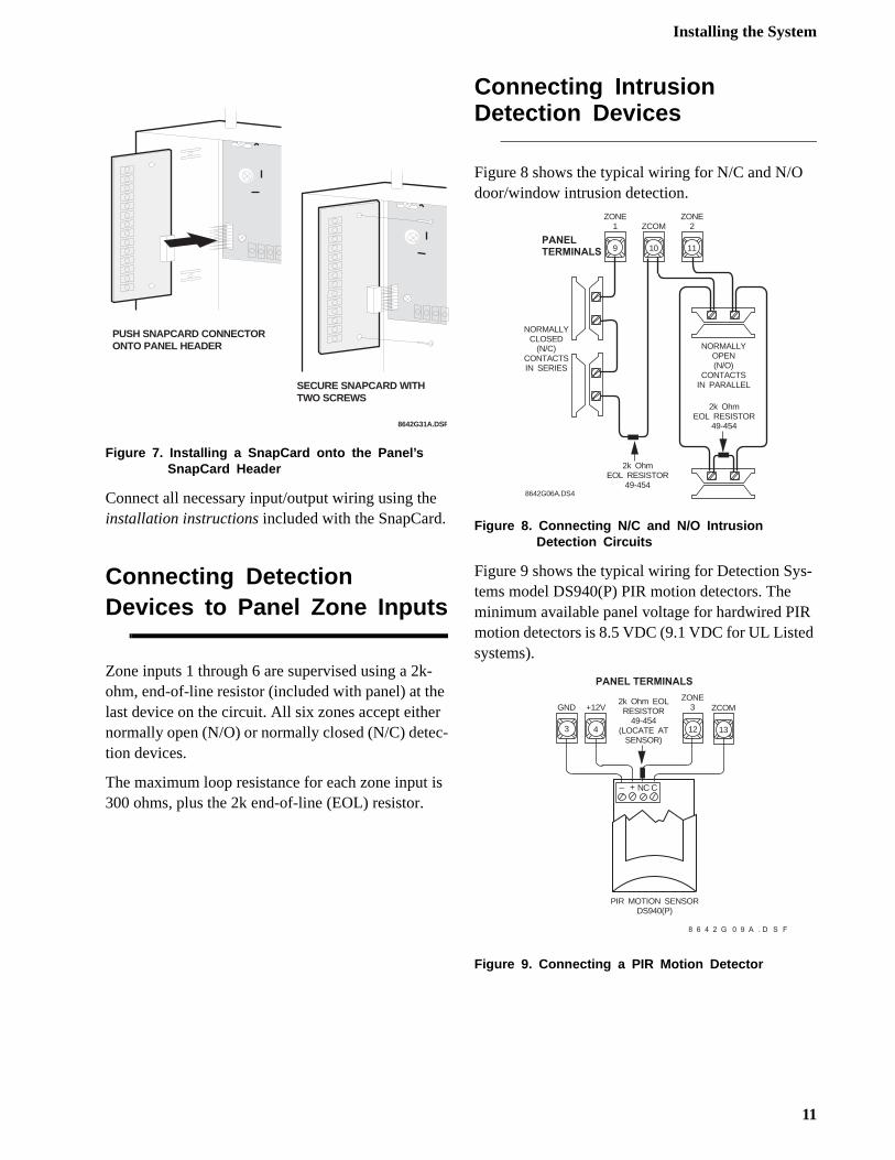
Figure 7. Installing a SnapCard onto the Panel’s SnapCard Header
Connect all necessary input/output wiring using the installation instructions included with the SnapCard.
Connecting Detection Devices to Panel Zone Inputs
Zone inputs 1 through 6 are supervised using a 2k-ohm, end-of-line resistor (included with panel) at the last device on the circuit. All six zones accept either normally open (N/O) or normally closed (N/C) detec-tion devices.
The maximum loop resistance for each zone input is 300 ohms, plus the 2k end-of-line (EOL) resistor.
Connecting IntrusionDetection Devices
Figure 8 shows the typical wiring for N/C and N/O door/window intrusion detection.
Figure 8. Connecting N/C and N/O IntrusionDetection Circuits
Figure 9 shows the typical wiring for Detection Systems model DS940(P) PIR motion detectors. The minimum available panel voltage for hardwired PIRmotion detectors is 8.5 VDC (9.1 VDC for UL Listedsystems).
Figure 9. Connecting a PIR Motion Detector
8642G31A.DSF
PUSH SNAPCARD CONNECTORONTO PANEL HEADER
SECURE SNAPCARD WITHTWO SCREWS
9 10 11
ZONE1 ZCOM
ZONE2
NORMALLYOPEN (N/O)
CONTACTSIN PARALLEL
2k OhmEOL RESISTOR
49-454
2k OhmEOL RESISTOR
49-454
NORMALLYCLOSED
(N/C)CONTACTSIN SERIES
P A N E LT E R M I N A L S
8642G06A.DS4
P A N E L T E R M I N A L S
8 6 4 2 G 0 9 A . D S F
2k Ohm EOLRESISTOR
49-454(LOCATE AT
SENSOR)4 12 13
ZONE3+12V ZCOM
PIR MOTION SENSORDS940(P)
_ + NC C
3
GND
11
Installing the System
e-
e e)
o
Connecting 2-Wire SmokeDetectors
Zone input 6 can be set up (in program mode) to ac-cept 12 VDC, 2-wire smoke detectors by the follow-ing manufacturers:
• System Sensor models 2100D, 2100TD, 2100S, 2100TS, 2400, 2400TH
• Sentrol (ESL) models 429AT, 521B, 521BXT—models 521B and 521BXT require the following dip switch settings: 1-on, 2-off.
WARNING!Use only the 2-wire smoke detector models de-scribed above. Alarm signals from other detectors may not be processed correctly if the panel has lost AC power and is operating only from the backup battery.
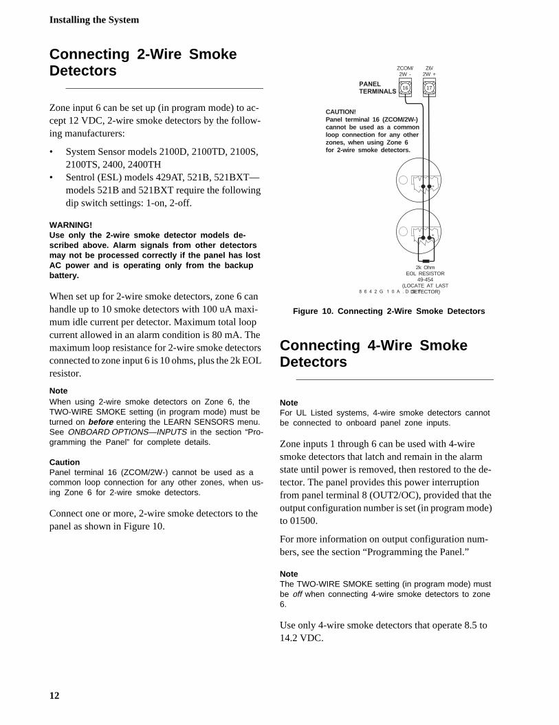
When set up for 2-wire smoke detectors, zone 6 can handle up to 10 smoke detectors with 100 uA maxi-mum idle current per detector. Maximum total loop current allowed in an alarm condition is 80 mA. The maximum loop resistance for 2-wire smoke detectors connected to zone input 6 is 10 ohms, plus the 2k EOL resistor.
NoteWhen using 2-wire smoke detectors on Zone 6, the TWO-WIRE SMOKE setting (in program mode) must be turned on before entering the LEARN SENSORS menu. See ONBOARD OPTIONS—INPUTS in the section “Pro-gramming the Panel” for complete details.
CautionPanel terminal 16 (ZCOM/2W-) cannot be used as a common loop connection for any other zones, when us-ing Zone 6 for 2-wire smoke detectors.
Connect one or more, 2-wire smoke detectors to the panel as shown in Figure 10.
Figure 10. Connecting 2-Wire Smoke Detectors
Connecting 4-Wire SmokeDetectors
NoteFor UL Listed systems, 4-wire smoke detectors cannot be connected to onboard panel zone inputs.
Zone inputs 1 through 6 can be used with 4-wire smoke detectors that latch and remain in the alarmstate until power is removed, then restored to the dtector. The panel provides this power interruption from panel terminal 8 (OUT2/OC), provided that thoutput configuration number is set (in program modto 01500.
For more information on output configuration num-bers, see the section “Programming the Panel.”
NoteThe TWO-WIRE SMOKE setting (in program mode) must be off when connecting 4-wire smoke detectors to zone 6.
Use only 4-wire smoke detectors that operate 8.5 t14.2 VDC.
16 17
ZCOM/2W -
Z6/2W +
+-
+-
2k OhmEOL RESISTOR
49-454(LOCATE AT LAST
DETECTOR)
P A N E LT E R M I N A L S
8 6 4 2 G 1 0 A . D S F
CAUTION!Panel terminal 16 (ZCOM/2W-)cannot be used as a commonloop connection for any otherzones, when using Zone 6for 2-wire smoke detectors.
12
Installing the System
-g g d
di-
is-2k
is-
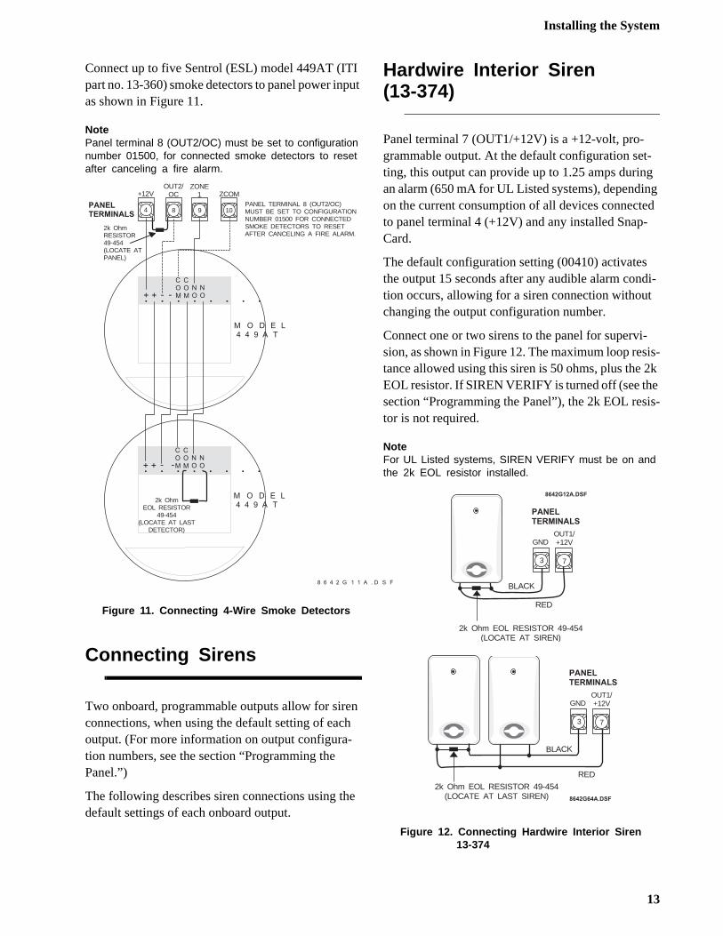
Connect up to five Sentrol (ESL) model 449AT (ITI part no. 13-360) smoke detectors to panel power input as shown in Figure 11.
NotePanel terminal 8 (OUT2/OC) must be set to configuration number 01500, for connected smoke detectors to reset after canceling a fire alarm.
Figure 11. Connecting 4-Wire Smoke Detectors
Connecting Sirens
Two onboard, programmable outputs allow for siren connections, when using the default setting of each output. (For more information on output configura-tion numbers, see the section “Programming thePanel.”)
The following describes siren connections using the default settings of each onboard output.
Hardwire Interior Siren(13-374)
Panel terminal 7 (OUT1/+12V) is a +12-volt, pro-grammable output. At the default configuration setting, this output can provide up to 1.25 amps durinan alarm (650 mA for UL Listed systems), dependinon the current consumption of all devices connecteto panel terminal 4 (+12V) and any installed Snap-Card.
The default configuration setting (00410) activatesthe output 15 seconds after any audible alarm contion occurs, allowing for a siren connection withoutchanging the output configuration number.
Connect one or two sirens to the panel for supervi-sion, as shown in Figure 12. The maximum loop restance allowed using this siren is 50 ohms, plus the EOL resistor. If SIREN VERIFY is turned off (see thesection “Programming the Panel”), the 2k EOL restor is not required.
NoteFor UL Listed systems, SIREN VERIFY must be on and the 2k EOL resistor installed.
Figure 12. Connecting Hardwire Interior Siren13-374
8 6 4 2 G 1 1 A . D S F
9 10
ZONE1 ZCOM
P A N E LT E R M I N A L S 8
OUT2/OC
+
COM. . . . . . . .+ - -
COM
NONO
M O D E L4 4 9 A T
+
COM. . . . . . . .+ - -
COM
NONO
M O D E L4 4 9 A T
2k OhmEOL RESISTOR
49-454(LOCATE AT LAST
DETECTOR)
4
+12V
PANEL TERMINAL 8 (OUT2/OC)MUST BE SET TO CONFIGURATIONNUMBER 01500 FOR CONNECTEDSMOKE DETECTORS TO RESETAFTER CANCELING A FIRE ALARM.
2k OhmRESISTOR49-454(LOCATE ATPANEL)
3 7
RED
BLACK
P A N E LT E R M I N A L S
8 6 4 2 G 1 2 A . D S F
GNDOUT1/+12V
2k Ohm EOL RESISTOR 49-454(LOCATE AT SIREN)
8 6 4 2 G 6 4 A . D S F
3 7
RED
BLACK
P A N E LT E R M I N A L S
GNDOUT1/+12V
2k Ohm EOL RESISTOR 49-454(LOCATE AT LAST SIREN)
13
Installing the System
ell )
-g
di-
d se
al-
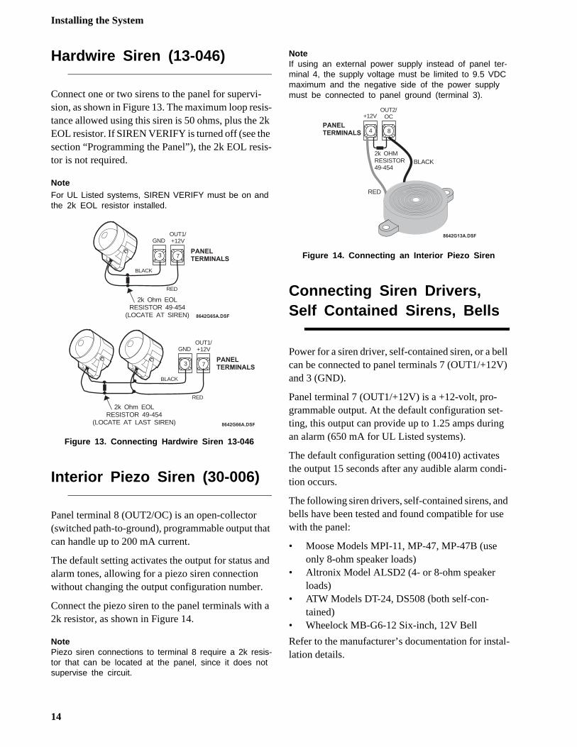
Hardwire Siren (13-046)
Connect one or two sirens to the panel for supervi-sion, as shown in Figure 13. The maximum loop resis-tance allowed using this siren is 50 ohms, plus the 2k EOL resistor. If SIREN VERIFY is turned off (see the section “Programming the Panel”), the 2k EOL resis-tor is not required.
NoteFor UL Listed systems, SIREN VERIFY must be on and the 2k EOL resistor installed.
Figure 13. Connecting Hardwire Siren 13-046
Interior Piezo Siren (30-006)
Panel terminal 8 (OUT2/OC) is an open-collector(switched path-to-ground), programmable output that can handle up to 200 mA current.
The default setting activates the output for status and alarm tones, allowing for a piezo siren connection without changing the output configuration number.
Connect the piezo siren to the panel terminals with a 2k resistor, as shown in Figure 14.
NotePiezo siren connections to terminal 8 require a 2k resis-tor that can be located at the panel, since it does not supervise the circuit.
NoteIf using an external power supply instead of panel ter-minal 4, the supply voltage must be limited to 9.5 VDC maximum and the negative side of the power supply must be connected to panel ground (terminal 3).
Figure 14. Connecting an Interior Piezo Siren
Connecting Siren Drivers, Self Contained Sirens, Bells
Power for a siren driver, self-contained siren, or a bcan be connected to panel terminals 7 (OUT1/+12Vand 3 (GND).
Panel terminal 7 (OUT1/+12V) is a +12-volt, pro-grammable output. At the default configuration setting, this output can provide up to 1.25 amps durinan alarm (650 mA for UL Listed systems).
The default configuration setting (00410) activatesthe output 15 seconds after any audible alarm contion occurs.
The following siren drivers, self-contained sirens, anbells have been tested and found compatible for uwith the panel:
• Moose Models MPI-11, MP-47, MP-47B (use only 8-ohm speaker loads)
• Altronix Model ALSD2 (4- or 8-ohm speaker loads)
• ATW Models DT-24, DS508 (both self-con-tained)
• Wheelock MB-G6-12 Six-inch, 12V Bell
Refer to the manufacturer’s documentation for instlation details.
3 7
GNDOUT1/+12V
RED
BLACK
P A N E LT E R M I N A L S
8 6 4 2 G 6 5 A . D S F
2k Ohm EOLRESISTOR 49-454
(LOCATE AT SIREN)
3 7
GNDOUT1/+12V
RED
BLACK
P A N E LT E R M I N A L S
8 6 4 2 G 6 6 A . D S F
2k Ohm EOLRESISTOR 49-454
(LOCATE AT LAST SIREN)
4 8P A N E LT E R M I N A L S
8 6 4 2 G 1 3 A . D S F
+12VOUT2/
OC
RED
BLACK2k OHMRESISTOR49-454
14
Installing the System
d n
w-.
-n-
a-s
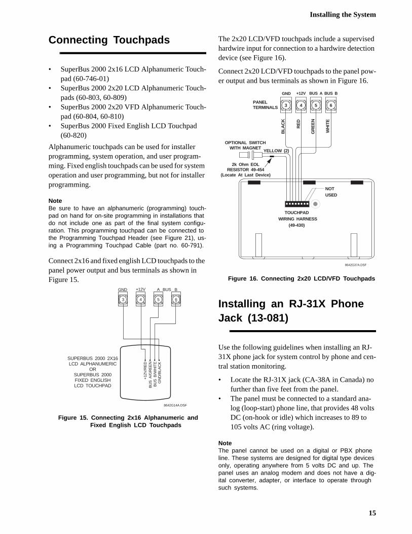
Connecting Touchpads
• SuperBus 2000 2x16 LCD Alphanumeric Touch-pad (60-746-01)
• SuperBus 2000 2x20 LCD Alphanumeric Touch-pads (60-803, 60-809)
• SuperBus 2000 2x20 VFD Alphanumeric Touch-pad (60-804, 60-810)
• SuperBus 2000 Fixed English LCD Touchpad(60-820)
Alphanumeric touchpads can be used for installer programming, system operation, and user program-ming. Fixed english touchpads can be used for system operation and user programming, but not for installer programming.
NoteBe sure to have an alphanumeric (programming) touch-pad on hand for on-site programming in installations that do not include one as part of the final system configu-ration. This programming touchpad can be connected to the Programming Touchpad Header (see Figure 21), us-ing a Programming Touchpad Cable (part no. 60-791).
Connect 2x16 and fixed english LCD touchpads to the panel power output and bus terminals as shown in Figure 15.
Figure 15. Connecting 2x16 Alphanumeric and Fixed English LCD Touchpads
The 2x20 LCD/VFD touchpads include a supervisehardwire input for connection to a hardwire detectiodevice (see Figure 16).
Connect 2x20 LCD/VFD touchpads to the panel poer output and bus terminals as shown in Figure 16
Figure 16. Connecting 2x20 LCD/VFD Touchpads
Installing an RJ-31X Phone Jack (13-081)
Use the following guidelines when installing an RJ31X phone jack for system control by phone and cetral station monitoring.
• Locate the RJ-31X jack (CA-38A in Canada) nofurther than five feet from the panel.
• The panel must be connected to a standard anlog (loop-start) phone line, that provides 48 voltDC (on-hook or idle) which increases to 89 to 105 volts AC (ring voltage).
NoteThe panel cannot be used on a digital or PBX phone line. These systems are designed for digital type devices only, operating anywhere from 5 volts DC and up. The panel uses an analog modem and does not have a dig-ital converter, adapter, or interface to operate through such systems.
3 4 5 6
SUPERBUS 2000 2X16LCD ALPHANUMERIC
ORSUPERBUS 2000FIXED ENGLISHLCD TOUCHPAD
GN
D/B
LAC
K
+12V
/RE
DB
US
A/G
RE
EN
BU
S B
/WH
ITE
8642G14A.DSF
+12V A BGND BUS
3 4 5 6
GND +12V BUS BBUS A
PANELTERMINALS
NOT USED
OPTIONAL SWITCHWITH MAGNET
YELLOW (2)
BLA
CK
RE
D
WH
ITE
GR
EE
N
TOUCHPAD WIRING HARNESS
(49-430)
8642G37A.DSF
2k Ohm EOLRESISTOR 49-454
(Locate At Last Device)
15
Installing the System
e .
-
• For full line seizure, install an RJ-31X phone jack on the premises phone line so the panel is ahead of all phones and other devices on the line. This allows the panel to take control of the phone line when an alarm occurs, even if the phone is in use or off-hook.
• If an analog line is not available, contact your customers’ telecommunications specialist and tell him/her you need an analog line off the phone switch (PBX mainframe) or a 1FB (stan-dard business line).
NoteConnecting the panel to an analog line off the phone switch places the panel ahead of the phone system, pre-venting panel access from phones on the premises. However, the panel can still be accessed from off-site phones.
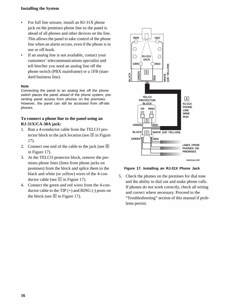
To connect a phone line to the panel using anRJ-31X/CA-38A jack:1. Run a 4-conductor cable from the TELCO pro-
tector block to the jack location (see A in Figure 17).
2. Connect one end of the cable to the jack (see B in Figure 17).
3. At the TELCO protector block, remove the pre-mises phone lines (lines from phone jacks on premises) from the block and splice them to the black and white (or yellow) wires of the 4-con-ductor cable (see C in Figure 17).
4. Connect the green and red wires from the 4-con-ductor cable to the TIP (+) and RING (-) posts on the block (see D in Figure 17).
Figure 17. Installing an RJ-31X Phone Jack
5. Check the phones on the premises for dial tonand the ability to dial out and make phone callsIf phones do not work correctly, check all wiringand correct where necessary. Proceed to the “Troubleshooting” section of this manual if problems persist.
BRN GRY
GRN RED
RE
D
WH
ITE
(OR
YE
LLO
W)
BLA
CK
TELCOPROTECTOR
BLOCK
GREEN RED
RING(-)
RJ-31XPHONELINEWIRERUN
GREEN RED
TIP(+)
LINES FROMPHONES ONPREMISES
RJ-31XJACK
GR
EE
N
BLACK WHITE (OR YELLOW)
A
B
C
D
8642G16A.DSF
16
Installing the System
wn
at-
ed
Connecting the Phone Line to the Panel with a DB-8 Cord
After installing the RJ-31X jack, you are ready to con-nect the phone line to the panel. A DB-8 cord (not in-cluded) uses a plug at one end for connecting to the RJ-31X module and flying leads on the other end for panel terminal connections.
To connect the DB-8 cord to the panel terminals and RJ-31X jack:1. Connect the green, brown, gray, and red flying
leads from the DB-8 cord to panel terminals 18, 19, 20, and 21 (see Figure 18).
2. Insert the DB-8 cord’s plug into the RJ-31X (see Figure 18).
Figure 18. Connecting the DB-8 Cord to the Panel and RJ-31X Jack
3. Check the phones on the premises for dial tone and the ability to dial out and make phone calls. If phones do not work correctly, check all wiring and correct where necessary. Proceed to the “Troubleshooting” section of this manual if prob-lems persist.
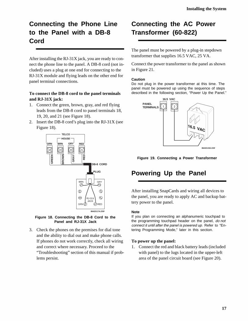
Connecting the AC PowerTransformer (60-822)
The panel must be powered by a plug-in stepdowntransformer that supplies 16.5 VAC, 25 VA.
Connect the power transformer to the panel as shoin Figure 21.
CautionDo not plug in the power transformer at this time. The panel must be powered up using the sequence of steps described in the following section, “Power Up the Panel.”
Figure 19. Connecting a Power Transformer
Powering Up the Panel
After installing SnapCards and wiring all devices tothe panel, you are ready to apply AC and backup btery power to the panel.
NoteIf you plan on connecting an alphanumeric touchpad to the programming touchpad header on the panel, do not connect it until after the panel is powered up. Refer to “En-tering Programming Mode,” later in this section.
To power up the panel:1. Connect the red and black battery leads (includ
with panel) to the lugs located in the upper-left area of the panel circuit board (see Figure 20).
TELCO
BRN GRY
GRN RED
GR
EE
N
BR
OW
N
GR
AY
RE
D
DB-8 CORD
19 20 21
HOUSE
GRY RED
RJ-31XJACK
PLUG
8642G17A.DSF
18
GRN BRN
PANELTERMINALS 1 2
16.5 VAC
8642G19A.DSF
17
Programming the Panel
o-
n de m
a-
ro-
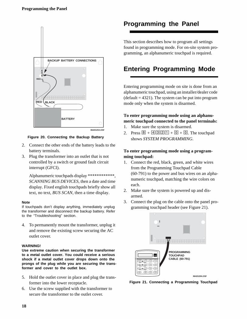
Figure 20. Connecting the Backup Battery
2. Connect the other ends of the battery leads to the battery terminals.
3. Plug the transformer into an outlet that is not controlled by a switch or ground fault circuit interrupt (GFCI).
Alphanumeric touchpads display ************, SCANNING BUS DEVICES, then a date and time display. Fixed english touchpads briefly show all text, no text, BUS SCAN, then a time display.
NoteIf touchpads don’t display anything, immediately unplug the transformer and disconnect the backup battery. Refer to the “Troubleshooting” section.
4. To permanently mount the transformer, unplug it and remove the existing screw securing the AC outlet cover.
WARNING!Use extreme caution when securing the transformer to a metal outlet cover. You could receive a serious shock if a metal outlet cover drops down onto the prongs of the plug while you are securing the trans-former and cover to the outlet box.
5. Hold the outlet cover in place and plug the trans-former into the lower receptacle.
6. Use the screw supplied with the transformer to secure the transformer to the outlet cover.
Programming the Panel
This section describes how to program all settingsfound in programming mode. For on-site system prgramming, an alphanumeric touchpad is required.
Entering Programming Mode
Entering programming mode on site is done from aalphanumeric touchpad, using an installer/dealer co(default = 4321). The system can be put into programode only when the system is disarmed.
To enter programming mode using an alphanu-meric touchpad connected to the panel terminals:1. Make sure the system is disarmed.
2. Press 8 + 4321 + 0 + 0. The touchpad shows SYSTEM PROGRAMMING.
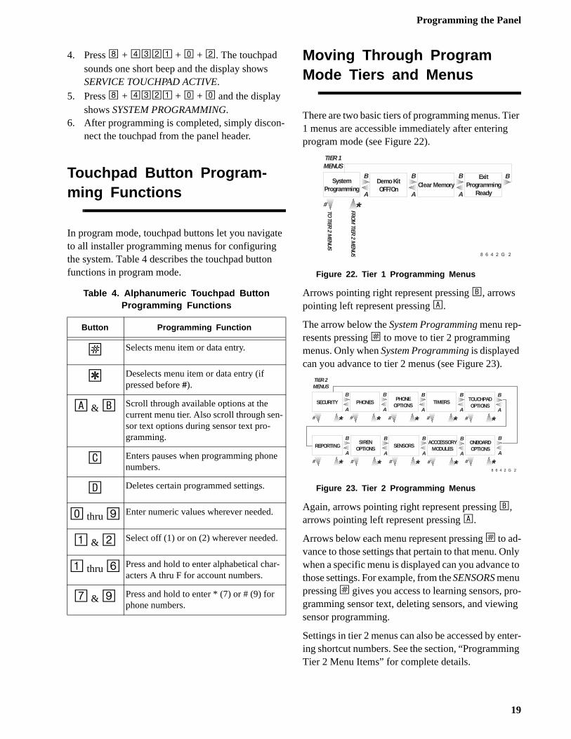
To enter programming mode using a program-ming touchpad:1. Connect the red, black, green, and white wires
from the Programming Touchpad Cable(60-791) to the power and bus wires on an alphnumeric touchpad, matching the wire colors oneach.
2. Make sure the system is powered up and dis-armed.
3. Connect the plug on the cable onto the panel pgramming touchpad header (see Figure 21).
Figure 21. Connecting a Programming Touchpad
8642G20A.DSF
BLA
CK
RED
BATTERY
BLACKRED
BACKUP BATTERY CONNECTIONS
8642G29A.DSF
S t a t u s
F e a t u r e s
p r e s s b o t h
L i g h t s
S y s t e m
A w a y
P a g e r
O f f
N o D e l a yp r e s s b o t h
p r e s s b o t h
T e s t S y s t e m W e e k l y
S i l e n t
S t a y
D *
7
0 #
8
B
A
4
1
5 6
2 3
B y p a s s
M e n u
C 9
PROGRAMMINGTOUCHPADCABLE (60-791)
18
Programming the Panel
ier
nly to
ro-ng
ter-ng
4. Press 8 + 4321 + 0 + 2. The touchpad sounds one short beep and the display shows SERVICE TOUCHPAD ACTIVE.
5. Press 8 + 4321 + 0 + 0 and the display shows SYSTEM PROGRAMMING.
6. After programming is completed, simply discon-nect the touchpad from the panel header.
Touchpad Button Program-ming Functions
In program mode, touchpad buttons let you navigate to all installer programming menus for configuring the system. Table 4 describes the touchpad button functions in program mode.
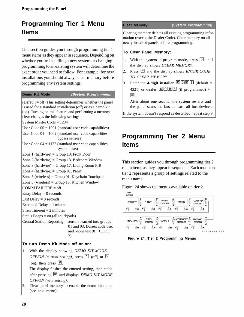
Moving Through Program Mode Tiers and Menus
There are two basic tiers of programming menus. T1 menus are accessible immediately after enteringprogram mode (see Figure 22).
Figure 22. Tier 1 Programming Menus
Arrows pointing right represent pressing B, arrows pointing left represent pressing A.
The arrow below the System Programming menu rep-resents pressing ƒ to move to tier 2 programming menus. Only when System Programming is displayed can you advance to tier 2 menus (see Figure 23).
Figure 23. Tier 2 Programming Menus
Again, arrows pointing right represent pressing B, arrows pointing left represent pressing A.
Arrows below each menu represent pressing ƒ to ad-vance to those settings that pertain to that menu. Owhen a specific menu is displayed can you advancethose settings. For example, from the SENSORS menu pressing ƒ gives you access to learning sensors, pgramming sensor text, deleting sensors, and viewisensor programming.
Settings in tier 2 menus can also be accessed by ening shortcut numbers. See the section, “ProgrammiTier 2 Menu Items” for complete details.
Table 4. Alphanumeric Touchpad Button Programming Functions
Button Programming Function
ƒ Selects menu item or data entry.
‚ Deselects menu item or data entry (if pressed before #).
A & B Scroll through available options at the current menu tier. Also scroll through sen-sor text options during sensor text pro-gramming.
C Enters pauses when programming phone numbers.
D Deletes certain programmed settings.
0 thru 9 Enter numeric values wherever needed.
1 & 2 Select off (1) or on (2) wherever needed.
1 thru 6 Press and hold to enter alphabetical char-acters A thru F for account numbers.
7 & 9 Press and hold to enter * (7) or # (9) for phone numbers.
#
SystemProgramming
Demo KitOFF/On
Clear MemoryExit
ProgrammingReadyA
B
A
B
A
B
TIER 1MENUS
B
*
8 6 4 2 G 2 1 A . D S F
TO TIER 2 MENUS
FROM TIER 2 M
ENUS
#
SECURITY PHONESPHONE
OPTIONSTIMERS TOUCHPAD
OPTIONSA
B
A
B
A
B
A
B
TIER 2MENUS
A
B
*
8 6 4 2 G 2 3 A . D S F
# * # * # * # *
REPORTINGSIREN
OPTIONS SENSORSACCCESSORY
MODULESA
B
A
B
A
B
A
B
# * # * # * # *
ONBOARDOPTIONS
A
B
# *
19
Programming the Panel
2 u on
-
.
3.
Programming Tier 1 Menu Items
This section guides you through programming tier 1 menu items as they appear in sequence. Depending on whether you’re installing a new system or changing programming to an existing system will determine the exact order you need to follow. For example, for new installations you should always clear memory before programming any system settings.
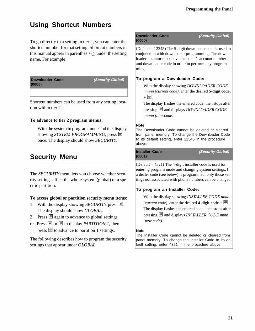
Programming Tier 2 Menu Items
This section guides you through programming tier menu items as they appear in sequence. Each mentier 2 represents a group of settings related to the menu name.
Figure 24 shows the menus available on tier 2.
Figure 24. Tier 2 Programming Menus
Demo Kit Mode (System Programming)
(Default = off) This setting determines whether the panel is used for a standard installation (off) or as a demo kit (on). Turning on this feature and performing a memory clear changes the following settings:
System Master Code = 1234
User Code 00 = 1001 (standard user code capabilities)
User Code 01 = 1002 (standard user code capabilities, bypass sensors)
User Code 04 = 1122 (standard user code capabilities, system tests)
Zone 1 (hardwire) = Group 10, Front Door
Zone 2 (hardwire) = Group 13, Bedroom Window
Zone 3 (hardwire) = Group 17, Living Room PIR
Zone 4 (hardwire) = Group 01, Panic
Zone 5 (wireless) = Group 01, Keychain Touchpad
Zone 6 (wireless) = Group 13, Kitchen Window
COMM FAILURE = off
Entry Delay = 8 seconds
Exit Delay = 8 seconds
Extended Delay = 1 minute
Siren Timeout = 2 minutes
Status Beeps = on (all touchpads)
Central Station Reporting = sensors learned into groups 01 and 03, Duress code use, and phone test (8 + CODE + 2)
To turn Demo Kit Mode off or on:
1. With the display showing DEMO KIT MODE
OFF/ON (current setting), press 1 (off) or 2
(on), then press ƒ.
The display flashes the entered setting, then stops
after pressing ƒ and displays DEMO KIT MODE
OFF/ON (new setting).2. Clear panel memory to enable the demo kit mode
(see next menu).
Clear Memory (System Programming)
Clearing memory deletes all existing programming information (except the Dealer Code). Clear memory on all newly installed panels before programming.
To Clear Panel Memory:
1. With the system in program mode, press B until
the display shows CLEAR MEMORY.
2. Press ƒ and the display shows ENTER CODE
TO CLEAR MEMORY.
3. Enter the 4-digit installer CODE (default =
4321) or dealer CODE (if programmed) +
ƒ.
After about one second, the system restarts andthe panel scans the bus to learn all bus devices
If the system doesn’t respond as described, repeat step
#
SECURITY PHONESPHONE
OPTIONSTIMERS TOUCHPAD
OPTIONSA
B
A
B
A
B
A
B
TIER 2MENUS
A
B
*
8 6 4 2 G 2 3 A . D S F
# * # * # * # *
REPORTINGSIREN
OPTIONS SENSORSACCCESSORY
MODULESA
B
A
B
A
B
A
B
# * # * # * # *
ONBOARDOPTIONS
A
B
# *
20
Programming the Panel
n
ter
If et-ed.
ter
Using Shortcut Numbers
To go directly to a setting in tier 2, you can enter the shortcut number for that setting. Shortcut numbers in this manual appear in parenthesis (), under the setting name. For example:
Shortcut numbers can be used from any setting loca-tion within tier 2.
To advance to tier 2 program menus:
With the system in program mode and the display showing SYSTEM PROGRAMMING, press ƒ once. The display should show SECURITY.
Security Menu
The SECURITY menu lets you choose whether secu-rity settings affect the whole system (global) or a spe-cific partition.
To access global or partition security menu items:1. With the display showing SECURITY, press ƒ.
The display should show GLOBAL.
2. Press ƒ again to advance to global settings
or--Press A or B to display PARTITION 1, then
press ƒ to advance to partition 1 settings.
The following describes how to program the security settings that appear under GLOBAL.
Downloader Code (Security-Global)(0000)
Downloader Code (Security-Global)(0000)
(Default = 12345) The 5-digit downloader code is used iconjunction with downloader programming. The down-loader operator must have the panel’s account numberand downloader code in order to perform any program-ming.
To program a Downloader Code:
With the display showing DOWNLOADER CODE nnnnn (current code), enter the desired 5-digit code,
+ ƒ.
The display flashes the entered code, then stops af
pressing ƒ and displays DOWNLOADER CODE
nnnnn (new code).
NoteThe Downloader Code cannot be deleted or cleared from panel memory. To change the Downloader Code to its default setting, enter 12345 in the procedure above.
Installer Code (Security-Global)(0001)
(Default = 4321) The 4-digit installer code is used for entering program mode and changing system settings. a dealer code (see below) is programmed, only those stings not associated with phone numbers can be chang
To program an Installer Code:
With the display showing INSTALLER CODE nnnn
(current code), enter the desired 4-digit code + ƒ.
The display flashes the entered code, then stops af
pressing ƒ and displays INSTALLER CODE nnnn
(new code).
NoteThe Installer Code cannot be deleted or cleared from panel memory. To change the Installer Code to its de-fault setting, enter 4321 in the procedure above.
21
Programming the Panel
ing
-
n ps s-
ld
The following describes how to program the security settings that appear under PARTITION 1.
Dealer Code (Security-Global)(0002)
(Default = none) The 4-digit dealer code is used to pre-vent unauthorized persons from changing the pro-grammed central station phone number. When changed from its default setting, all central station phone numbers can be changed only by entering program mode using the dealer code. (If a Dealer Code is programmed, entering program mode with the installer code lets you program all system settings except for the Dealer Code and central station phone numbers.)
To program a Dealer Code:
With the display showing DEALER CODE ****,
enter the desired 4-digit code + ƒ.
The display flashes the entered code, then stops after
pressing ƒ and displays the new code.
To delete a Dealer Code:
With the display showing DEALER CODE nnnn (current code), press D.The display shows DEALER CODE ****.
NoteThe Dealer Code cannot be deleted by clearing panel memory.
Account Number (Security—Partition 1)(0010)
(Default = 00000) The account number is used as panel (or customer) identification for the central monitoring station. The panel sends the account number every time it reports to the central station. Account numbers must be 1 to 10 characters long.
Alpha characters A-F can be assigned to the account number by pressing and holding buttons 1-6 respectively, until the character appears.
To program an Account Number:
With the display showing ACCOUNT NUMBER nnnnn (current number), enter the desired account
number, then press ƒ.
The display flashes the entered number, then stops
after pressing ƒ and displays the new number.
Quick Arm (Security—Partition 1)(0011)
(Default = off) Quick Arm allows system arming without using an access code. When turned on, the system armlevel can be increased from Level 1-OFF to LEVEL 2-STAY, from Level 1-OFF to LEVEL 3-AWAY, or from Level 2-STAY to LEVEL 3-AWAY without entering an access code.
A valid access code is still required to decrease the arming level or disarm the system.
To turn Quick Arm off or on:
With the display showing QUICK ARM OFF/ON
(current setting), press 1 (off) or 2 (on), then
press ƒ.
The display flashes the entered setting, then stops
after pressing ƒ and displays the new setting.
Quick Exit (Security—Partition 1)(0012)
(Default = on) This setting determines whether users caopen and close a standard entry/exit door (sensor grou10 and 19 only) while the system is armed, without cauing an alarm.
One example would be going out to get the morning paper while the system is armed. Another example woube leaving the armed premises without having to disarmand re-arm the system.
When turned on, pressing D on a touchpad while the system is armed starts a 2-minute timer that allows onestandard entry/exit door to be activated once (opened, then closed).
When turned off, the system must be disarmed before opening any protected door.
NoteFor UL Listed systems, Quick Exit must be turned off.
To turn Quick Exit off or on:
With the display showing QUICK EXIT OFF/ON
(current setting), press 1 (off) or 2 (on), then
press ƒ.
The display flashes the entered setting, then stops
after pressing ƒ and displays the new setting.
22
Programming the Panel
-
a-
s-
nd
n
Exit Extension (Security—Partition 1)(0013)
(Default = on) This setting determines whether the user can re-enter and exit again through an entry/exit delay door, without disarming and re-arming the system. This helps prevent exit faults and false alarms by allowing users to re-enter the premises for a forgotten item.
When turned on, the panel restarts the exit delay timer if the user re-enters the premises through a designated delay door, before the exit delay time expires.
When turned off, the exit delay timer does not restart if the user re-enters the premises, forcing them to disarm the system to avoid setting off an accidental alarm.
NoteFor UL Listed systems, Exit Extension must be turned off.
To turn Exit Extension off or on:
With the display showing EXIT EXTENSION OFF/
ON (current setting), press 1 (off) or 2 (on), then
press ƒ.
The display flashes the entered setting, then stops
after pressing ƒ and displays the new setting.
Auto Stay Arming (Security—Partition 1)(0014)
(Default = on) This setting determines whether the sys-tem automatically arms to STAY (level 2) if the user arms the system to AWAY (level 3) without exiting the pre-mises. This can help prevent accidental alarms by deacti-vating interior motion sensors during occupied arming periods.
With the feature turned on, the user arms the system to AWAY. Touchpads (and other status sounders) emit one exit delay beep every four seconds, then one every sec-ond during the last 10 seconds. If the exit delay time expires with no standard delay sensor activation, the sys-tem automatically arms to STAY.
NoteArming the system to AWAY with No Delay overrides the Auto Stay Arming feature.
To turn Auto Stay Arming off or on:
With the display showing AUTO STAY ARMING
OFF/ON (current setting), press 1 (off) or 2 (on),
then press ƒ.
The display flashes the entered setting, then stops
after pressing ƒ and displays the new setting.
Keyswitch Sensor (Security—Partition 1)(0015)
(Default = none) This feature lets users arm and disarmthe system using a keyswitch wired to a hardwire zone input or a wireless door/window sensor.
For example, if sensor/zone 1 is designated as the keyswitch sensor and the system is disarmed, tripping the sensor/zone arms the system to AWAY. If the system isarmed to STAY or AWAY, tripping the sensor disarms thesystem. The panel reports opening, closing, and force armed reports (if turned on) to the central monitoring sttion.
A bypassed keyswitch sensor cannot arm or disarm thesystem.
During an audible alarm, keyswitch sensors can disarmthe system (which sends a cancel report to the central monitoring station), but cannot arm the system. The sytem can be armed only after siren timeout expires.
Keyswitch sensors test the same as any other sensor ado not arm or disarm the system during a sensor test.
To assign a Keyswitch Sensor:
With the display showing KEYSWITCH SENSOR n (current sensor number), enter the desired sensor
number (01-16), then press ƒ.
The display flashes the entered sensor number, the
stops after pressing ƒ and displays the new number.
23
Programming the Panel
e-ar-
s
-d
Phones Menu
The PHONES menu lets you set up central station rporting for the system (global) and pager reports (ptition specific).
The following describes how to program the settingthat appear under CS PHONE 1-2.
Duress Code (Security—Partition 1)(0016)
(Default = none) The duress code is a unique 4-digit access code that allows users to operate the system and, at the same time, instructs the panel to send a silent alarm report to the central station.
NoteTo use this feature, the DURESS OPTION setting under the REPORTING—PARTITION 1 menu must be turned on.
CautionBecause using duress codes often results in false alarms due to code entry errors, it is strongly recom-mended not to program duress codes.
If a duress code is absolutely necessary, their use with an Interrogator is highly recommended to reduce false alarms and accidental dispatches.
To program a Duress Code:
With the display showing DURESS CODE ****,
enter the desired 4-digit duress code, then press ƒ.
The display flashes the entered setting, then stops
after pressing ƒ and displays the new code.
To delete a Duress Code:
With the display showing DURESS CODE nnnn
(current code), press D.
The display shows DURESS CODE ****.
Phone Number (Phones—CS Phone 1-2)(0100-cs phone 1, 0110-cs phone 2)
(Default = none) This setting is used for programming the central station receiver’s phone number. Phone numbers can be 1 to 24 digits long, including pauses or * an
# characters. To enter pauses, press C. To enter * , press
and hold 7 for one second. To enter #, press and hold 9 for one second.
NoteThe PHONE NUMBER menus are not accessible if a Dealer Code is programmed and the Installer Code is used to enter installer programming mode. To access these menus when a Dealer Code is programmed, you must enter installer programming mode using the Deal-er Code.
NoteCall-waiting services should be disabled to prevent in-terrupting panel communication to the central monitor-ing station or pager. To program a dialing prefix that disables call-waiting, see the CALL WAIT CANCEL set-ting under the menu PHONE OPTIONS—GLOBAL.
To program a Central Station Phone Number:
With the display showing PHONE NUMBER _ (or current number), enter the desired phone number +
ƒ.
The display flashes the entered number, then stops
after pressing ƒ and displays the new number.
To delete a Central Station Phone Number:
With the display showing PHONE NUMBER
(current number), press D.The display shows PHONE NUMBER _.
24
Programming the Panel
-
s-
t-
d
ts -
to e
High Level Rpts (Phones—CS Phone 1-2)(0101-cs phone 1, 0111-cs phone 2)
(Defaults: CS Phone 1 = on, CS Phone 2 = off) This set-ting determines whether the following conditions report to the central station:
Fire, Police, Auxiliary, Duress, and Freeze alarms, No Activity, Receiver Failure (or jam), System Tamper (40 incorrect keypresses or touchpad supervisory), and enter-ing or exiting Sensor Test mode.
To turn High-Level Reports off or on:
With the display showing HIGH LEVEL RPTS OFF/
ON (current setting), press 1 (off) or 2 (on), then
press ƒ.
The display flashes the entered setting, then stops
after pressing ƒ and displays the new setting.
Low Level Rpts (Phones—CS Phone 1-2)(0102-cs phone 1, 0112-cs phone 2)
(Defaults: CS Phone 1 = on, CS Phone 2 = off) This set-ting determines whether non-alarm conditions report to the central station, such as Force Armed, Hardwire Zone Trouble (open or short), Supervisory (wireless devices), Low Battery (wireless devices), and other non-alarm related conditions.
To turn Low-Level Reports off or on:
With the display showing LOW LEVEL RPTS OFF/
ON (current setting), press 1 (off) or 2 (on), then
press ƒ.
The display flashes the entered setting, then stops
after pressing ƒ and displays the new setting.
Open/Close Rpts (Phones—CS Phone 1-2)(0103-cs phone 1, 0113-cs phone 2)
(Defaults: all off) This setting determines whether opening and closing reports are sent to the central station. When turned on, the panel sends a closing report whenthe system is armed and an opening report when the sytem is disarmed.
NoteTo use this feature, the OPENING REPORTS and CLOSING REPORTS settings under the REPORTING menu must be turned on.
To turn Opening/Closing Reports off or on:
With the display showing OPEN/CLOSE RPTS
OFF/ON (current setting), press 1 (off) or 2 (on),
then press ƒ.
The display flashes the entered setting, then stops
after pressing ƒ and displays the new setting.
Backup (Phones—CS Phone 1-2)(0104-cs phone 1, 0114-cs phone 2)
(Defaults: CS Phone 1 = on, CS Phone 2 = off) This seting determines whether the panel uses another pro-grammed central station phone number for reporting if three initial attempts are unsuccessful. CS PHONE 1 isbacked up by CS PHONE 2, and CS PHONE 2 is backeup by CS PHONE 1. The panel makes up to 16 attemp(8 per phone number), alternating between the two programmed phone numbers.
For example, if BACKUP is on and three failed reporting attempts occur using CS PHONE 1, the panel switches CS PHONE 2 for three more reporting attempts. If thesattempts fail, the panel switches back to CS PHONE 1 for five more reporting attempts and, if necessary, switches back to CS PHONE 2 for five final attempts.
To turn Backup off or on:
With the display showing BACKUP OFF/ON (cur-
rent setting), press 1 (off) or 2 (on), then press
ƒ.
The display flashes the entered setting, then stops
after pressing ƒ and displays the new setting.
25
Programming the Panel
er-
The following describes how to program the phone settings that appear under PAGER PHONE 1 thru 3.
Reporting Format (Phones—CS Phone 1-2)(0105-cs phone 1, 0115-cs phone 2)
(Defaults: all CID) This setting determines whether the panel uses the SIA or CID (Contact ID) reporting format for central station communication.
To select SIA or CID Reporting Format:
With the display showing REPORTING FORMAT
SIA/CID (current setting), press 1 (for SIA) or 2
(for CID), then press ƒ.
The display flashes the entered setting, then stops
after pressing ƒ and displays the new setting.
Phone Number (Phones—Pager Phone 1-3)(0120-pager 1, 0130-pager 2, 0140-pager 3)
(Default = none) This setting is used for programming a phone number that communicates to a pager. Phone num-bers can be 1 to 24 digits long, and include pauses or *
and # characters. To enter pauses, press C. To enter * ,
press and hold 7 for one second. To enter #, press and
hold 9 for one second.
NoteCall-waiting services should be disabled to prevent in-terrupting panel communication to the central monitor-ing station or pager. To program a dialing prefix that disables call-waiting, see the CALL WAIT CANCEL set-ting under the menu PHONE OPTIONS—GLOBAL.
To program a Pager Phone Number:
With the display showing PHONE NUMBER _ (or current number), enter the desired pager phone
number including pauses, then press ƒ.
The display flashes the entered number, then stops
after pressing ƒ and displays the new number.
To delete a Pager Phone Number:
With the display showing PHONE NUMBER (cur-
rent number), press D.
The display shows PHONE NUMBER _.
High Level Rpts (Phones—Pager Phone 1-3(0121-pager 1, 0131-pager 2, 0141-pager 3)
(Default = on) This setting determines whether the fol-lowing alarm conditions report to a pager:
Fire, Police, Auxiliary, Duress, and Freeze alarms, No Activity, Receiver Failure (or jam), System Tamper (40 incorrect keypresses or touchpad supervisory), and enting or exiting Sensor Test mode.
To turn High-Level Reports off or on:
With the display showing HIGH LEVEL RPTS OFF/
ON (current setting), press 1 (off) or 2 (on), then
press ƒ.
The display flashes the entered setting, then stops
after pressing ƒ and displays the new setting.
Low Level Rpts (Phones—Pager Phone 1-3)(0122-pager 1, 0132-pager 2, 0142-pager 3)
(Default = off) This setting determines whether the fol-lowing non-alarm conditions report to a pager, such as Force Armed, Hardwire Zone Trouble (open or short), Supervisory (wireless devices), Low Battery (wireless devices), and other non-alarm related conditions.
To turn Low-Level Reports off or on:
With the display showing LOW LEVEL RPTS OFF/
ON (current setting), press 1 (off) or 2 (on), then
press ƒ.
The display flashes the entered setting, then stops
after pressing ƒ and displays LOW LEVEL RPTS
OFF/ON (new setting).
26
Programming the Panel
t
The following describes how to program the phonesettings that appear under DOWNLOADER PHONE.
Phone Options Menu
The PHONE OPTIONS menu lets you set up systemphone access and communications that affect the whole system (global) or a specific partition.
The following describes how to program the phoneoption settings that appear under GLOBAL.
Open/Close Rpts (Phones—Pager Phone 1-3)(0123-pager 1, 0133-pager 2, 0143-pager 3)
(Default = off) This setting determines whether opening and closing reports are sent to a pager. When turned on, the panel sends a closing report when the system is armed and an opening report when the system is dis-armed.
NoteTo use this feature, the OPENING REPORTS and CLOSING REPORTS settings under the REPORTING menu must be turned on.
To turn Opening/Closing Reports off or on:
With the display showing OPEN/CLOSE RPTS
OFF/ON (current setting), press 1 (off) or 2 (on),
then press ƒ.
The display flashes the entered setting, then stops
after pressing ƒ and displays the new setting.
Latchkey Reports (Phones—Pager Phone 1-3)(0124-pager 1, 0134-pager 2, 0144-pager 3)
(Default = on) This setting determines whether the panel reports to a pager when the system is disarmed, using the latchkey modifier (6) and latchkey designated access code.
To turn Latchkey reports off or on:
With the display showing LATCHKEY REPORTS
OFF/ON (current setting), press 1 (off) or 2 (on),
then press ƒ.
The display flashes the entered setting, then stops
after pressing ƒ and displays the new setting.
Streamlining (Phones—Pager Phone 1-3)(0125-pager 1, 0135-pager 2, 0145-pager 3)
(Default = on) This setting whether the panel includes (off) or excludes (on) the account number when reporting to a pager.
To turn Streamlining off or on:
With the display showing STREAMLINING OFF/
ON (current setting), press 1 (off) or 2 (on), then
press ƒ.
The display flashes the entered setting, then stops
after pressing ƒ and displays the new setting.
Phone Number (Downloader Phone)(0150)
(Default = none) This setting is used for programming the phone number of a computer used for programmingthe panel from off-site. Phone numbers can be 1 to 24 digits long, including pauses or * and # characters. To
enter pauses, press C. To enter * , press and hold 7 for
one second. To enter #, press and hold 9 for one second.
NoteCall-waiting services should be disabled to prevent in-terrupting panel communication to the central monitor-ing station or pager. To program a dialing prefix that disables call-waiting, see the CALL WAIT CANCEL set-ting under the menu PHONE OPTIONS—GLOBAL.
To program a downloader phone number:
With the display showing PHONE NUMBER (cur-rent number), enter the desired phone number +
ƒ.
The display flashes the entered number, then stops
after pressing ƒ and displays the new setting.
Phone Test (Phone Options—Global)(02000)
(Default = on) This setting determines if the user can, aany time, test the communication from the panel to the central station or a pager by entering 8 + CODE + 2.
To turn the Phone Test setting off or on:
With the display showing PHONE TEST OFF/ON
(current setting), press 1 (off) or 2 (on), then
press ƒ.
The display flashes the entered setting, then stops
after pressing ƒ and displays the new setting.
27
Programming the Panel
el hat
el
Auto Phone Test (Phone Options—Global)(02001)
(Default = off) This setting determines if the panel sends a phone test automatically to the central station or a pager on a predetermined schedule. (Refer to the “Phone Test Freq.” and “Next Phone Test” settings found under TIM-ERS—GLOBAL).
To turn Automatic Phone Test off or on:
With the display showing AUTO PHONE TEST
OFF/ON (current setting), press 1 (off) or 2 (on),
then press ƒ.
The display flashes the entered setting, then stops
after pressing ƒ and displays the new setting.
Auto Test Reset (Phone Options—Global)(02002)
(Default = on) This setting determines whether the Auto Phone Test interval is reset after any successful report to the central monitoring station. (Refer to the “Phone Test Freq.” and “Next Phone Test” settings found under TIM-ERS—GLOBAL).
When turned on, the panel reports an Auto Phone Test only if no other reports are made during any Phone Test Freq. time period. Any other successful panel report to the central monitoring station resets the Next Phone Test setting to the Phone Test Freq. value.
When turned off, an Auto Phone Test is always reported according to the Phone Test Freq. setting, even if the panel makes any other reports to the central monitoring station during that time period.
NotePHONE TEST FREQ must be set to 2 or higher for this feature to work.
To turn Auto Test Reset off or on:
With the display showing AUTO TEST RESET OFF/
ON (current setting), press 1 (off) or 2 (on), then
press ƒ.
The display flashes the entered setting, then stops
after pressing ƒ and displays the new setting.
Comm Failure (Phone Options—Global)(02003)
(Default = on) This setting determines whether the panactivates trouble beeps to alert users on the premises tcommunication to the central station failed. Failure noti-fication occurs after the third unsuccessful reporting attempt to the central station/pager.
NoteFor UL Listed systems, Comm Failure must be turned on.
To turn Communication Failure notification off or on:
With the display showing COMM FAILURE OFF/
ON (current setting), press 1 (off) or 2 (on), then
press ƒ.
The display flashes the entered setting, then stops
after pressing ƒ and displays the new setting.
DTMF Dialing (Phone Options—Global)(02004)
(Default = on) This setting determines whether the panuses DTMF tones (on) or pulse (off) for dialing pro-grammed phone numbers.
To turn DTMF Dialing off or on:
With the display showing DTMF DIALING OFF/ON
(current setting), press 1 (off) or 2 (on), then
press ƒ.
The display flashes the entered setting, then stops
after pressing ƒ and displays the new setting.
28
Programming the Panel
g he
l l
r.
Dialer Abort (Phone Options—Global)(02005)
(Default = on) This setting determines whether users can stop the panel’s first dialing attempt (within the Dialer Abort Delay time setting), to report to the central station. When turned on, alarm reports from sensors in groups 00-20, 34, and 35 can be aborted by entering 1 + CODE within the Dialer Abort Delay time setting (defaulted to 30 seconds). Cancel and restoral reports from these sen-sor groups are also aborted, if the related alarm report was aborted. Other reports that can be aborted include System Alarm Tamper/Cancel, No Activity Alarm/Can-cel, Touchpad Police and Auxiliary Panic/Cancel, Recent Closing, and Two Trip Error. Fire alarm reports to the central station cannot be aborted.
To turn Dialer Abort off or on:
With the display showing DIALER ABORT OFF/ON
(current setting), press 1 (off) or 2 (on), then
press ƒ.
The display flashes the entered setting, then stops
after pressing ƒ and displays the new setting.
Dial Abort Delay (Phone Options—Global)(02006)
(Default = 30 seconds) This setting determines how much time (15-120 seconds) the user has to enter the dis-arm command, to prevent the panel from reporting to the central monitoring station.
To change the Dial Abort Delay:
With the display showing DIAL ABORT DELAY nn (current setting), enter the desired time (15-120 sec-
onds), then press ƒ.
The display flashes the entered setting, then stops
after pressing ƒ and displays the new setting.
Cancel Message (Phone Options—Global)(02007)
(Default = on) This setting determines whether the panel reports a cancel message to the central monitoring sta-tion, after disarming the system to clear an alarm condi-tion.
To turn Cancel Message off or on:
With the display showing CANCEL MESSAGE
OFF/ON (current setting), press 1 (off) or 2 (on),
then press ƒ.
The display flashes the entered setting, then stops
after pressing ƒ and displays the new setting.
Pager Delay (Phone Options—Global)(02008)
(Default = 15 seconds) This setting determines how lona report is delayed to a pager (00 - 30 seconds), after tpanel dials the pager number.
NoteThe Pager Delay time should not be set below 5 sec-onds, unless absolutely necessary.
To set the Pager Delay time:
With the display showing PAGER DELAY nn (cur-rent setting), enter a two digit time (00 - 30), then
press ƒ.
The display flashes the entered setting, then stops
after pressing ƒ and displays the new setting.
Call Wait Cancel (Phone Options—Global)(02009)
(Default = none) This feature lets you set up a dialing prefix to disable the call waiting feature before the panemakes its first dialing attempt to any programmed centramonitoring station, pager, or downloader phone numbeThe prefix can be up to eight digits. For prefixes that
require dialing * or #, press and hold for two seconds 7
(for *) or 9 (for #).
To set up Call Wait Cancel:
With the display showing CALL WAIT CANCEL __ (or current setting), enter the desired prefix , then
press ƒ.
The display flashes the entered setting, then stops
after pressing ƒ and displays the new setting.
29
Programming the Panel
m or
not
r-
al ). d
The following describes how to program the phone option settings that appear under PARTITION 1.
Timers Menu
The TIMERS menu lets you set up the various systefeature times that affect the whole system (global) a specific partition.
The following describes how to program the timer settings that appear under GLOBAL.
Remote Access (Phone Options—Partition 1)(0210)
(Default = on) This setting determines whether the panel can be accessed from off-site for downloader program-mer.
To turn Remote Access off or on:
With the display showing REMOTE ACCESS OFF/
ON (current setting), press 1 (off) or 2 (on), then
press ƒ.
The display flashes the entered setting, then stops
after pressing ƒ and displays the new setting.
Ring/Hang/Ring (Phone Options—Partition 1)(0211)
(Default = on) This setting determines how the panel picks up (seizes) the phone line for downloader program-ming by remote access.
NoteThe REMOTE ACCESS setting (above) must be turned on for this feature to work.
When turned on, the caller must listen for one or two full rings, hang up, then call the premises again within the next 10-40 seconds. The system answers after the first ring. The “on” setting is recommended if an answering machine shares the phone line with the panel.
When turned off, the caller must listen for 12 full rings before the system answers. The “off” setting is recom-mended if there is no answering machine sharing the phone line with the panel.
To turn Ring/Hang/Ring access off or on:
With the display showing RING/HANG/RING OFF/
ON (current setting), press 1 (off) or 2 (on), then
press ƒ.
The display begins flashing the entered selection, then stops and displays the new setting.
Supervisory Time (Timers—Global)(0300)
(Default = 03:00) This setting determines what time of day the panel sends supervisory, low battery, or auto phone test reports to the central station. The setting is based on a 24-hour timer so a.m. and p.m. settings are needed.
NoteThe panel’s clock must be set with the correct time for accurate supervisory time reporting. Refer to the “User Programming” section for setting the panel’s clock.
To set the Supervisory Time:
With the display showing SUPERVISORY TIME HH:MM (current setting), enter the desired 4-digit time value (for example, enter 1330 to set the supe
visory time for 1:30 p.m.), then press ƒ.
The display flashes the entered setting, then stops
after pressing ƒ and displays the new setting.
RF Tx Timeout (Timers—Global)(0301)
(Default = 12 hours) This setting determines how manyhours (2 - 24) the panel has to receive at least one signfrom a wireless device (learned into a supervised groupIf the panel does not receive a signal from any supervisewireless device within the set time, the panel reports a supervisory condition to the central station.
NoteFor U.L. Listed residential burglary installations, the RF Tx Timeout must be set to 12 hours or less.
To set the RF Tx Timeout:
With the display showing RF TX TIMEOUT nn HOURS (current setting), enter the desired 2-digit
timeout value (02 - 24), then press ƒ.
The display flashes the entered setting, then stops
after pressing ƒ and displays the new setting.
30
Programming the Panel
s-
The following describes how to program the timer settings that appear under PARTITION 1.
Phone Test Freq. (Timers—Global)(0302)
(Default = 7 days) This setting determines how often the panel sends the automatic phone test (see Auto Phone Test under Phone Options—Global) to the central station or a pager. The phone test frequency can be set to report every 1 to 255 days.
To set the Phone Test Freq:
With the display showing PHONE TEST FREQ nnn DAYS (current setting), enter the number of days
(1 - 255), then press ƒ.
The display flashes the entered setting, then stops
after pressing ƒ and displays the new setting.
Next Phone Test (Timers—Global)(0303)
(Default = 7 days) This setting determines how many days (1 - 255) until the next automatic phone test occurs. When setting up Phone Test Freq. (see above), Next Phone Test must be set to accurately count the number of days left in the cycle before the next phone test occurs. This setting should be the same or less than the Phone Test Freq. setting.
To set the Next Phone Test:
With the display showing NEXT PHONE TEST nnn DAYS (current setting), enter the number of days
(1 - 255), then press ƒ.
The display flashes the entered setting, then stops
after pressing ƒ and displays the new setting.
Output Trip Time (Timers—Global)(0304)
(Default = 4 seconds) This setting determines how long onboard and SnapCard outputs are activated, when con-figured for a momentary trip.
To set the Output Trip Time:
With the display showing OUTPUT TRIP TIME nn SECONDS (current setting), enter the number of
seconds (1 - 12), then press ƒ.
The display flashes the entered setting, then stops
after pressing ƒ and displays the new setting.
Activity Timeout (Timers—Global)(0305)
(Default = 24 hours) This setting determines how long the system goes (1 - 42 hours) without user interaction and device activation before sending a ‘no activity’ report to the central station.
To set the Activity Timeout:
With the display showing ACTIVITY TIMEOUT nn HOURS (current setting) enter the desired 2-digit
time value (1 - 42), then press ƒ.
The display flashes the entered setting, then stops
after pressing ƒ and displays the new setting.
Daylight Savings (Timers—Global)(0306)
(Default = on) This setting determines whether the panel’s clock automatically adjusts for daylight savings time changes in spring and fall.
To turn Daylight Savings off or on:
With the display showing DAYLIGHT SAVINGS
OFF/ON (current setting), press 1 (off) or 2 (on),
then press ƒ.
The display flashes the entered setting, then stops
after pressing ƒ and displays the new setting.
Entry Delay (Timers—Partition 1)(0310)
(Default = 32 seconds) This setting determines how much time (32 - 240 seconds) users have to disarm thesystem after entering the armed premises through a deignated delay door, to avoid causing an alarm.
NoteFor UL Listed residential installations, the Entry Delay must be set to 45 seconds or less.
To set the Entry Delay:
With the display showing ENTRY DELAY nnn SEC-ONDS (current setting), enter the desired time value
(32 - 240 using 8-second intervals), then press ƒ.
The display flashes the entered setting, then stops
after pressing ƒ and displays the new setting.
31
Programming the Panel
d
d
d ).
d n.
Touchpad Options Menu
The TOUCHPAD OPTIONS menu lets you set up touchpad panic and arming operation.
The following describes how to program the touchpaoption settings that appear under PARTITION 1.
Exit Delay (Timers—Partition 1)(0311)
(Default = 64 seconds) This setting determines how much time (48 - 184 seconds) the user has to leave the premises through a designated delay door after arming the system, to avoid causing an alarm.
NoteFor UL Listed residential installations, the Exit Delay must be set to 60 seconds or less.
To set the Exit Delay:
With the display showing EXIT DELAY nnn SEC-ONDS (current setting), enter the desired time value
(48 - 184 using 8-second intervals), then press ƒ.
The display flashes the entered setting, then stops
after pressing ƒ and displays the new setting.
Extended Delay (Timers—Partition 1)(0312)
(Default = 4 minutes) This setting determines how much time (1 - 8 minutes) the user has to enter or exit the pre-mises through a designated extended delay door, without causing an alarm.
NoteFor UL Listed systems, Extended Delay shall not be used.
To set the Extended Delay:
With the display showing EXTENDED DELAY nn MINUTES (current setting), enter the desired time
value (1 - 8), then press ƒ.
The display flashes the entered setting, then stops
after pressing ƒ and displays the new setting.
Siren Timeout (Timers—Partition 1)(0313)
(Default = 4 minutes) This setting determines how long sirens sound (1 - 30 minutes) if no one is present to dis-arm the system.
NoteFor UL Listed systems, Siren Timeout must be set to 4 minutes or more.
To set the Siren Timeout:
With the display showing SIREN TIMEOUT nn MINUTES (current setting), enter the desired time
value (1 - 30), then press ƒ.
The display flashes the entered setting, then stops
after pressing ƒ and displays the new setting.
Fire Panic (Touchpad Options—Partition 1)(0400)
(Default = on) This setting determines whether touchpafire panic buttons are enabled (on) or disabled (off).
To change the Fire Panic setting:
With the display showing FIRE PANIC OFF/ON
(current setting), press 1 (off) or 2 (on), then
press ƒ. The display flashes the entered setting,
then stops after pressing ƒ and displays the new
setting.
Aux. Panic (Touchpad Options—Partition 1)(0401)
(Default = on) This setting determines whether touchpaauxiliary panic buttons are enabled (on) or disabled (off
To change the Auxiliary Panic setting:
With the display showing AUXILIARY PANIC OFF/
ON (current setting), press 1 (off) or 2 (on), then
press ƒ.
The display flashes the entered setting, then stops
after pressing ƒ and displays the new setting.
Police Panic (Touchpad Options—Partition 1)(0402)
(Default = on) This setting determines whether touchpapolice panic buttons are enabled (on) or disabled (off) o
To change the Police Panic setting:
With the display showing POLICE PANIC OFF/ON
(current setting), press 1 (off) or 2 (on), then
press ƒ. The display flashes the entered setting,
then stops after pressing ƒ and displays the new
setting.
32
Programming the Panel
al
g
l s ys-
el ry
Reporting Menu
The REPORTING menu lets you set up which systemevents (global or partition) are reported to the centrmonitoring station.
The following describes how to program the reportinsettings that appear under GLOBAL.
Keychain TP Arm (Touchpad Options—Partition 1)(0403)
(Default = off) This setting determines whether keychain touchpads arm the system directly to AWAY with NO DELAY (on) or increments from OFF to STAY, or from STAY to AWAY (off).
To change the Keychain Touchpad Arming setting:
With the display showing KEYCHAIN TOUCHPAD
ARM OFF/ON (current setting), press 1 (off) or 2
(on), then press ƒ.
The display flashes the entered setting, then stops
after pressing ƒ and displays the new setting.
Star Is No Delay (Touchpad Options—Partition 1)(0404)
(Default = off) This setting determines whether the key-chain touchpad star button controls an onboard/SnapCard output (off) or the NO DELAY feature (on).
To change the Keychain Star Is No Delay set-ting:
With the display showing STAR IS NO DELAY OFF/
ON (current setting), press 1 (off) or 2 (on), then
press ƒ.
The display flashes the entered setting, then stops
after pressing ƒ and displays the new setting.
24-Hour Tamper (Reporting—Global)(05000)
(Default = off) This setting determines whether the panesounds sirens and reports a tamper alarm when wirelessensor tamper switches are activated, even when the stem is disarmed (OFF).
To turn 24-Hour Tamper off or on:
With the display showing 24-HOUR TAMPER OFF/
ON (current setting), press 1 (off) or 2 (on), then
press ƒ.
The display flashes the entered setting, then stops
after pressing ƒ and displays the new setting.
Buffer Control (Reporting—Global)(05001)
(Default = off) This setting determines whether all sys-tem events are logged in the buffer (off) or if only arminglevel changes are logged in the buffer (on).
To turn Buffer Control off or on:
With the display showing BUFFER CONTROL
OFF/ON (current setting), press 1 (off) or 2 (on),
then press ƒ.
The display flashes the entered setting, then stops
after pressing ƒ and displays the new setting.
Back In Service (Reporting—Global)(05002)
(Default = on) This setting determines whether the panreports to the central station after AC and backup battepower are restored after an extended power outage.
To turn Back In Service reports off or on:
With the display showing BACK IN SERVICE OFF/
ON (current setting), press 1 (off) or 2 (on), then
press ƒ.
The display flashes the entered setting, then stops
after pressing ƒ and displays the new setting.
33
Programming the Panel
l g
l
e
Bypass Reports (Reporting—Global)(05003)
(Default = off) This setting determines if the panel reports to the central station or a pager whenever sensors or zones are bypassed.
To turn Bypass Reports off or on:
With the display showing BYPASS REPORTS OFF/
ON (current setting), press 1 (off) or 2 (on), then
press ƒ.
The display flashes the entered setting, then stops
after pressing ƒ and displays the new setting.
Low CPU Battery (Reporting—Global)(05004)
(Default = on) This setting determines whether the panel reports a low panel battery to the central station or pager, before shutting down.
To turn Low CPU Battery reports off or on:
With the display showing LOW CPU BATTERY
OFF/ON (current setting), press 1 (off) or 2 (on),
then press ƒ.
The display flashes the entered setting, then stops
after pressing ƒ and displays the new setting.
Battery Restoral (Reporting—Global)(05005)
(Default = off) This setting determines whether the panel reports to the central monitoring station or pager, when a wireless sensor reports to the panel after battery replace-ment.
To turn Battery Restoral reports off or on:
With the display showing BATTERY RESTORAL
OFF/ON (current setting), press 1 (off) or 2 (on),
then press ƒ.
The display flashes the entered setting, then stops
after pressing ƒ and displays the new setting.
Buffer Full Rpt (Reporting—Global)(05006)
(Default = off) This setting determines whether the panesends an event buffer full report to the central monitorinstation when the event buffer is nearly full.
To turn Buffer Full Report off or on:
With the display showing BUFFER FULL RPT
OFF/ON (current setting), press ƒ.
Press 1 (off) or 2 (on), then press ƒ.
The display flashes the entered setting, then stops
after pressing ƒ and displays the new setting.
Zone Restorals (Reporting—Global)(05007)
(Default = off) This setting determines whether the panereports a restoral to the central monitoring station or pager for wireless or hardwire zones in alarm, before thalarm is canceled.
NoteAs with all ITI panels, hardwire smoke detectors con-nected to Concord or SnapCard hardwire zones do not send restorals.
To turn Zone Restoral reporting off or on:
With the display showing ZONE RESTORALS OFF/
ON (current setting), press 1 (off) or 2 (on), then
press ƒ.
The display flashes the entered setting, then stops
after pressing ƒ and displays the new setting.
34
Programming the Panel
l l
l d
Two Trip Error (Reporting—Global)(05008)
(Default = off) This setting determines if the panel sends an error report to the central monitoring station when a two-trip alarm is not verified (see “ALARM VERIFY” later in this section and “Appendix A: Table A3. Sensor Group Characteristics”).
If this feature is turned on and a second sensor trip does not occur within a 4-minute time period, the panel sends a TWO TRIP ERROR report to the central monitoring station.
When this feature is turned off, the panel does not send error reports.
NoteFor UL Listed systems, Two Trip Error must be turned off.
To turn Two Trip Error off or on:
With the display showing TWO TRIP ERROR OFF/
ON (current setting), press 1 (off) or 2 (on), then
press ƒ.
The display flashes the entered setting, then stops
after pressing ƒ and displays the new setting.
TP Panic RPT FMT (Reporting—Global)(05009)
(Default = off) This setting determines how the panel reports touchpad panic alarms to the central station.
When turned on, touchpad panic alarms report using the following 3-digit codes:Medical—596, Auxiliary—597, Police—598, Fire—599
When turned off, touchpad panic alarms report using a 3-digit code from 500 to 503, with the last digit identifying the touchpad device number.
To turn TP Panic RPT FMT off or on:
With the display showing TP PANIC RPT FMT
OFF/ON (current setting), press 1 (off) or 2 (on),
then press ƒ.
The display flashes the entered setting, then stops
after pressing ƒ and displays the new setting.
AC Failure (Reporting—Global)(05010)
(Default = off) This setting determines whether the panereports to the central station after AC power to the paneis out for 15 minutes.
Note
For UL Listed systems, AC Failure must be turned on.
To turn AC Failure reports off or on:
With the display showing AC FAILURE OFF/ON
(current setting), press 1 (off) or 2 (on), then
press ƒ.
The display flashes the entered setting, then stops
after pressing ƒ and displays the new setting.
Receiver Failure (Reporting—Global)(05011)
(Default = off) This setting determines whether the panereports if no wireless sensor signals have been receivefor two hours, or if the receiver is being jammed (con-stant signal).
NoteFor U.L. Listed installations that include wireless devic-es, this feature must be on.
To turn Receiver Failure reports off or on:
With the display showing RECEIVER FAILURE
OFF/ON (current setting), press 1 (off) or 2 (on),
then press ƒ.
The display flashes the entered setting, then stops
after pressing ƒ and displays the new setting.
RF Low Bat Rpt (Reporting—Global)(05012)
(Default = weekly) This setting determines whether thepanel reports to the central monitoring station or pager daily or weekly, when a wireless device reports a low battery condition to the panel.
To set RF Low Battery Report to daily or weekly:
With the display showing RF LOW BAT RPT
DAILY/WEEKLY (current setting), press 1 (daily)
or 2 (weekly), then press ƒ.
The display flashes the entered setting, then stops
after pressing ƒ and displays the new setting.
35
Programming the Panel
s
l
l er
The following describes how to program the settingthat appear under REPORTING—PARTITION 1.
RF Supv Report (Reporting—Global)(05013)
(Default = weekly) This setting determines whether the panel reports to the central monitoring station or pager daily or weekly, when the panel detects a wireless device supervisory condition.
To set RF Supv Report to daily or weekly:
With the display showing RF SUPV REPORT
DAILY/WEEKLY (current setting), press 1 (daily)
or 2 (weekly), then press ƒ.
The display flashes the entered setting, then stops
after pressing ƒ and displays the new setting.
Swinger Limit (Reporting—Global)(05014)
(Default = 1) This setting determines the maximum num-ber of times a sensor/zone in groups 00 - 20, 29, or 34 can go into alarm during a single arming period, before the panel automatically bypasses that sensor/zone. The automatic bypass is logged into the event buffer.
When set to 1, the panel automatically bypasses a sensor/zone, the first time it causes an alarm. When set to 2, the panel automatically bypasses a sensor/zone if it causes a second alarm during the same arming period.
A sensor/zone that is automatically bypassed can be auto-matically unbypassed during the same arming period, only if the system receives no further activations from that sensor/zone over the next 48 - 50 hours.
Changing the arming level clears all automatically bypassed sensors/zones and resets the Swinger Limit count on all sensors/zones.
To set the Swinger Limit:
With the display showing SWINGER LIMIT n (cur-
rent setting), press 1 or 2, then press ƒ.
The display flashes the entered setting, then stops
after pressing ƒ and displays the new setting.
Opening Reports (Reporting—Partition 1)(0510)
(Default = off) This setting determines whether the panesends an opening report to the central station or pager,after disarming the system.
NoteTo use this feature, the OPEN/CLOSE REPORTS set-tings under the PHONES—CS PHONE 1-2 and/or PHONES—PAGER PHONE 1-3 menus must be turned on for the specific CS Phone or Pager Phone number.
To turn Opening Reports off or on:
With the display showing OPENING REPORTS
OFF/ON (current setting), press 1 (off) or 2 (on),
then press ƒ.
The display flashes the entered setting, then stops
after pressing ƒ and displays the new setting.
Closing Reports (Reporting—Partition 1)(0511)
(Default = off) This setting determines whether the panesends a closing report to the central station or pager, aftarming the system.
NoteTo use this feature, the OPEN/CLOSE REPORTS set-tings under the PHONES—CS PHONE 1-2 and/or PHONES—PAGER PHONE 1-3 menus must be turned on for the specific CS Phone or Pager Phone number.
To turn Closing Reports off or on:
With the display showing CLOSING REPORTS
OFF/ON (current setting), press 1 (off) or 2 (on),
then press ƒ.
The display flashes the entered setting, then stops
after pressing ƒ and displays the new setting.
36
Programming the Panel
l
l
10
le
Recent Closings (Reporting—Partition 1)(0512)
(Default = on) This setting determines whether the panel sends a recent closing report to the central station or a pager, if an alarm occurs within two minutes after the exit delay time expires. Such a report is used to identify a possible exit fault.
To turn Recent Closings off or on:
With the display showing RECENT CLOSINGS
OFF/ON (current setting), press 1 (off) or 2 (on),
then press ƒ.
The display flashes the entered setting, then stops
after pressing ƒ and displays the new setting.
No Activity (Reporting—Partition 1)(0513)
(Default = off) This setting determines whether the panel sends a no activity report to the central station or pager, if there is no system activity within a preset time period (see TIMERS—ACTIVITY TIMEOUT).
To turn No Activity reports off or on:
With the display showing NO ACTIVITY OFF/ON
(current setting), press 1 (off) or 2 (on), then
press ƒ.
The display flashes the entered setting, then stops
after pressing ƒ and displays the new setting.
Duress Option (Reporting—Partition 1)(0514)
(Default = off) This setting determines whether the sys-tem can be controlled using a programmed duress code (see SECURITY—PARTITION 1—DURESS CODE).
CautionBecause using duress codes often results in false alarms due to code entry errors, it is strongly recom-mended not to program any duress codes.
If a duress code is absolutely necessary, their use with an Interrogator is highly recommended to reduce false alarms and accidental dispatches.
To turn Duress Option off or on:
With the display showing DURESS OPTION OFF/
ON (current setting), press 1 (off) or 2 (on), then
press ƒ.
The display flashes the entered setting, then stops
after pressing ƒ and displays the new setting.
Force Armed (Reporting—Partition 1)(0515)
(Default = off) This setting determines whether the panereports to the central monitoring station when a user force arms the system.
Force Armed occurs if the user presses BYPASS whenarming the system with open sensors/zones protesting.
NoteAuto Force Armed always reports to the central moni-toring station.
Auto Force Armed occurs if the user does not press BY-PASS when arming the system with open sensors/zones protesting and the siren time expires.
NoteFor UL Listed systems, Force Armed must be turned off.
To turn Force Armed off or on:
With the display showing FORCE ARMED OFF/ON
(current setting), press 1 (off) or 2 (on), then
press ƒ.
The display flashes the entered setting, then stops
after pressing ƒ and displays the new setting.
Alarm Verify (Reporting—Partition 1)(0516)
(Default = off) This setting determines whether the panereports to the central monitoring station after a single sensor/zone trip (off) or waits for a second trip before reporting (on).
This setting affects sensors/zones learned into groups through 20. If Alarm Verify is set to on, group 18 responds the same as group 17. See “Appendix A, TabA.3: Sensor Group Characteristics.”
NoteFor UL Listed systems, Alarm Verify must be turned off.
To turn Alarm Verify off or on:
With the display showing ALARM VERIFY OFF/ON
(current setting), press 1 (off) or 2 (on), then
press ƒ.
The display flashes the entered setting, then stops
after pressing ƒ and displays the new setting.
37
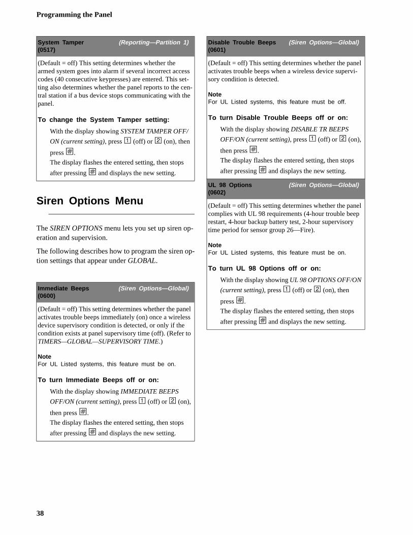
Programming the Panel
l -
l
Siren Options Menu
The SIREN OPTIONS menu lets you set up siren op-eration and supervision.
The following describes how to program the siren op-tion settings that appear under GLOBAL.
System Tamper (Reporting—Partition 1)(0517)
(Default = off) This setting determines whether the armed system goes into alarm if several incorrect access codes (40 consecutive keypresses) are entered. This set-ting also determines whether the panel reports to the cen-tral station if a bus device stops communicating with the panel.
To change the System Tamper setting:
With the display showing SYSTEM TAMPER OFF/
ON (current setting), press 1 (off) or 2 (on), then
press ƒ.
The display flashes the entered setting, then stops
after pressing ƒ and displays the new setting.
Immediate Beeps (Siren Options—Global)(0600)
(Default = off) This setting determines whether the panel activates trouble beeps immediately (on) once a wireless device supervisory condition is detected, or only if the condition exists at panel supervisory time (off). (Refer to TIMERS—GLOBAL—SUPERVISORY TIME.)
NoteFor UL Listed systems, this feature must be on.
To turn Immediate Beeps off or on:
With the display showing IMMEDIATE BEEPS
OFF/ON (current setting), press 1 (off) or 2 (on),
then press ƒ.
The display flashes the entered setting, then stops
after pressing ƒ and displays the new setting.
Disable Trouble Beeps (Siren Options—Global)(0601)
(Default = off) This setting determines whether the paneactivates trouble beeps when a wireless device supervisory condition is detected.
NoteFor UL Listed systems, this feature must be off.
To turn Disable Trouble Beeps off or on:
With the display showing DISABLE TR BEEPS
OFF/ON (current setting), press 1 (off) or 2 (on),
then press ƒ.
The display flashes the entered setting, then stops
after pressing ƒ and displays the new setting.
UL 98 Options (Siren Options—Global)(0602)
(Default = off) This setting determines whether the panecomplies with UL 98 requirements (4-hour trouble beeprestart, 4-hour backup battery test, 2-hour supervisory time period for sensor group 26—Fire).
NoteFor UL Listed systems, this feature must be on.
To turn UL 98 Options off or on:
With the display showing UL 98 OPTIONS OFF/ON
(current setting), press 1 (off) or 2 (on), then
press ƒ.
The display flashes the entered setting, then stops
after pressing ƒ and displays the new setting.
38
Programming the Panel
y.
e
.
The following describes how to program the settings that appear under SIREN OPTIONS—PARTITION 1
Sensors Menu
The SENSORS menu gives you access to the follow-ing:
• LEARN SENSORS—lets you learn hardwire zones and wireless sensors into panel memory and assign zones/sensors to specific partitions.
• SENSOR TEXT—lets you program sensor text for zone/sensor identification.
• DELETE SENSORS—lets you delete zones/sen-sors from panel memory.
• EDIT SENSORS—lets you view and/or change sensor/zone group assignment, view sensor num-ber and text assignments of learned sensors/zones, identify whether zone is wireless or hard-wire, and indicates sensor/zone/touchpad input N/C or N/O configuration.
The following describes how to program the sensor settings that appear under LEARN SENSORS.
NoteIf 2-wire smoke detectors are connected to hardwire zone input 6, the TWO-WIRE SMOKE setting must be turned on before entering the LEARN SENSORS menu. See ONBOARD OPTIONS—INPUTS later in this section.
Siren Verify (Siren Options—Partition 1)(0610)
(Default = off) This setting determines whether the panel monitors sirens connected to panel terminal 7(OUT1/+12V).
When turned on, sirens connected to panel terminals3 (GND) and 7 (OUT1/+12V) require a 2k EOL resistor. Refer to “Installing the System—Connecting Piezo Sirens” for complete details.
NoteFor UL Listed systems, this feature must be on.
To turn Siren Verify off or on:
With the display showing SIREN VERIFY OFF/ON
(current setting), press 1 (off) or 2 (on), then
press ƒ.
The display flashes the entered setting, then stops
after pressing ƒ and displays the new setting.
Learn Sensors (Sensors)(070)
(Default = none) The following describes how to learn hardwire zones and wireless devices into panel memor
To Learn Sensors into panel memory:
1. With the display showing SENSORS, press # and the display shows LEARN SENSORS.
2. Press # and the display shows SENSOR GROUP 0.
3. Enter the desired 2-digit sensor group + ƒ (see
Table A.4 in “Appendix A” for a description of all sensor group characteristics). The display shows TRIP SENSOR nn, where nn is the dis-played (next available) sensor number.
4. To change the displayed sensor number, enter th
desired 2-digit sensor number + ƒ.
5. With the desired sensor number displayed, trip the sensor or zone as follows:
• Hardwire Zones—trip the zone into the alarm state.
• Wireless Sensors—follow the instructions included with each sensor.Wireless Door/Window Sensors with External Contacts—place the external contact in the alarmcondition, then activate the sensor’s tamper switch.
• Handheld Wireless Touchpads—press and hold the BYPASS button until the touchpad LED flashes.
• Keychain Touchpads—press and hold the lock and unlock buttons together until the touchpad LED flashes.
• ELM Keychain Touchpads—a.) Press and release the unlock button twice quickly, then press and hold until the LED flashes three timesb.) Press and release the unlock button once quickly, then press and hold until the LED flashes two times. c.) Press and hold the unlock button until the LED flashes once.
6. Continue tripping sensors to learn them into theselected sensor group. To stop learning sensors
into a group, press ‚ twice and start again from
step 1 (LEARN SENSORS) to learn sensors into another group (or use the EDIT SENSORS menu to change group assignment after learning the sensor/zone).
39
Programming the Panel
l
ed.
Sensor Text (Sensors)(071)
(Default = none) Use the following guidelines for pro-gramming text to identify zone/sensor locations.
• There are 16 character/word locations or “Item Numbers” for each zone/sensor name. Item num-bers for each character/word appear in “Appendix A, Table A4.”
• If a desired word does not appear in the list, cre-ate it using characters (custom text).
• When using words, spaces between them appear automatically. When creating words using charac-ters, you must reserve an item number for a ‘space’ after creating the word.
• Each character or word uses up one item number. For example, a word from the list counts as one item number. A created word, such as BOY’S counts as six item numbers—4 letters, 1 apostro-phe, and 1 space.
• Plan ahead before programming sensor text. You may need to abbreviate words you create, to avoid running out of item numbers.
To program Sensor Text:
1. With the display showing LEARN SENSORS,
press B until the display shows SENSOR TEXT.
2. Press ƒ and the display shows TEXT FOR SN 01.
3. Press ƒ and the display shows:
Sn 01 ITEM 00000 -where ITEM 00 is the first character/word location and 000 is the 3-digit character/word number.
4. Enter the 3-digit number of the desired character/word or scroll forward through the numbers by
pressing B or backward by pressing A. If you
make a mistake, simply enter the correct 3-digit number or continue scrolling through choices.
5. Press ƒ to accept the displayed choice and the dis-
play shows:Sn 01 ITEM 01000 -
6. Repeat steps 4 and 5 as needed to complete the zone/sensor name.
7. Press ‚ after entering the last 3-digit character/
word number. The display shows the complete text name. For example:TEXT FOR SN 01FRONT ENTRY DOOR
Delete Sensors (Sensors)(072)
(Default = none) The following describes how to removehardwire zone and wireless sensor numbers from panememory.
NoteDeleting sensors does not delete sensor text associated with the deleted sensor number. To delete sensor text, enter the SENSOR TEXT menu and enter 000 (nulls) for each item number.
To Delete Sensors from panel memory:
1. With the display showing LEARN SENSORS,
press B until the display shows DELETE SEN-
SORS.
2. Press ƒ and the display shows DELETE SN NN
(lowest zone/sensor number in panel memory).
3. Press ƒ to delete the displayed sensor or enter the
desired sensor number, then press ƒ.
The display flashes the entered number, then stops and shows DELETE SENSOR NN DONE.
Repeat steps 2 and 3 until all desired sensors are delet
40
Programming the Panel
er, u
-
:
t
e
s
Accessory Modules Menu
The ACCESSORY MODULES menu gives you access to the following:
• BUS DEVICES—this menu lets you read bus device unit numbers, assign bus devices to a par-tition, and other features associated with a spe-cific bus device.
• SNAPCARD—this menu lets you set the configu-ration number for each SnapCard output.
The following describes how to program the set-tings that appear under ACCESSORY MODULES—BUS DEVICES.NoteMost settings under ACCESSORY MODULES—BUS DE-VICES have no shortcut numbers.
Edit Sensors (Sensors)(073)
(Default = none) This menu lets you view the assign-ments for each learned zone/sensor. For example, the dis-play shows:
S01 P1 G13 NC HWBACK DOOR
where S01 = zone/sensor number, P1 = partition 1, G13 = sensor group 13, NC = normally closed, HW = hard-wired, and BACK DOOR is the programmed text name.
You can also change the zone/sensor group assignment, eliminating the need to delete and re-learn the zone/sensor.
To Edit Sensors:
1. With the display showing LEARN SENSORS,
press B until the display shows EDIT SENSORS.
2. Press ƒ and the display shows the lowest sensor
number zone/sensor assignments.
3. Press A or B to scroll through all learned zone/
sensor number assignments.
4. When the desired zone/sensor is displayed press ƒ.
The display shows SENSOR GROUP nn (current group assignment).
5. Enter the desired group number, then press ƒ.
The display shows the new group assignment.
Unit - ID (Acc. Modules—Bus Devices)(0800 thru 0803)
(Default = none) This menu lets you identify all con-nected bus devices, each device address, unit ID numband other configurations based on a specific device. Yocan also delete learned bus device addresses.
To identify bus device Unit and ID:
1. With the display showing BUS DEVICES, press
ƒ. The display shows the bus device unit num
ber and the 8-digit unit ID number. For exampleUNIT - ID
0—02110185where 0 is the bus device unit number and 02110185 is the unit ID number.
NoteTo help identify bus devices, the 8-digit unit ID number is also located on a label on the back of each Super-Bus 2000 device.
2. Press A or B to identify all other bus device unit
numbers (0-3) and identification numbers.
To delete learned bus device unit numbers:
1. With the display showing BUS DEVICES, press
ƒ. The display shows the bus device set to uni
number 0.
2. Press A or B until the bus device unit number you
want to delete is displayed.
3. Press D. The display changes the unit number to
NONE.
Device ID (Acc. Modules—Bus Devices)
(Default = none) This menu lets you change a bus devicID number when replacing a defective bus device.
To change a Device ID:
1. With the display showing the desired touchpad,
press ƒ. The display shows DEVICE ID (current
ID).
2. Enter the ID of the new bus device, then press ƒ.
The display flashes the entered selection, then stop
after pressing ƒ and shows the new setting.
3. Exit programming mode.4. Remove AC and battery power from the panel.5. Replace the defective bus device with a new one.6. Apply AC and battery power to the panel.
41
Programming the Panel
s
s-
set
The following describes how to program the settingthat appear under SNAPCARDS.
Status Beeps (Acc. Modules—Bus Devices)
(Default = on) This setting determines whether the selected touchpad sounds status beeps. Each touchpad can be set individually. This feature is usually turned off if a touchpad is located in or near bedrooms, to avoid dis-turbing persons sleeping.
NoteFor UL Listed systems, Status Beeps must be turned on.
To turn touchpad Status Beeps on or off:
1. With the display showing the desired touchpad,
press ƒ then B once. The display shows
TOUCHPAD OPTIONS.
2. Press ƒ and the display shows STATUS BEEPS
OFF/ON (current setting).
3. Press 1 (off) or 2 (on) to select the desired setting,
then press ƒ.
The display flashes the entered selection, then stops
after pressing ƒ and shows the new setting.
Key Beeps (Acc. Modules—Bus Devices)
(Default = on) This setting determines whether selected touchpads sound beeps when their buttons are pressed. This feature is usually turned off if a touchpad is located in or near bedrooms, to avoid disturbing persons sleep-ing.
To turn Key Beeps on or off:
1. With the display showing the desired touchpad,
press ƒ + B + ƒ + B. The display shows
KEY BEEPS OFF/ON (current setting).
2. Press 1 (off) or 2 (on) to select the desired setting,
then press ƒ.
The display flashes the entered selection, then stops
after pressing ƒ and shows the new setting.
Output 1, 2, 3, 4 (Acc. Modules—SnapCards)(081000—output 1, 081010—output 2,081020—output 3, 081030—output 4)
(Defaults: Output 1 = 01400, Output 2 = 00410,Output 3 = 00903, Output 4 = 01003) This setting lets you assign the 5-digit configuration number for each SnapCard relay output, that determines which system event activates the output and the duration or time the output is activated.
The first three digits represent the trigger number of anevent such as, an alarm, open sensor, or arming the sytem.
The last two digits represent how the output responds such as, momentary, sustained (or latched), or for a pretime.
Tables A6 - A10 in “Appendix A” identify system event trigger and response numbers.
To assign configuration numbers to SnapCard Relay outputs:
1. With the display showing SNAPCARDS, press
ƒ. The display shows OUTPUT PROGRAM-
MING.
2. Press ƒ again and the display shows OUTPUT 1.
3. Press A or B to select the desired output (1 - 4),
then press ƒ. The display shows OUTPUT n (cur-
rent setting).4. Enter the desired 5-digit configuration number for
this output, then press ƒ.
The display flashes the entered number, then stops
after pressing ƒ and shows the new setting.
42
Programming the Panel
r
t--
is
s-
set
Onboard Options Menu
The ONBOARD OPTIONS menu lets you set up the following built-in options:
INPUTS—this menu lets you set panel zone input 6 for 2-wire smoke operation and turn the smoke verifi-cation feature off/on.
OUTPUTS—this menu lets you assign the panel’s two built-in outputs to partitions and set their config-uration numbers.
The following describes how to program the set-tings that appear under ONBOARD OPTIONS—IN-PUTS.
Smoke Verify (Onboard Options—Inputs)(0900)
(Default = off) This setting determines whether the panel requires two alarm signals within five minutes (on) from 2-wire smoke detectors connected to panel zone input 6 and/or SnapCard zone inputs, or any other hardwire zone learned into sensor group 26 (FIRE), before activating system sirens and reporting to a central station or pager.
NoteFor California State Fire Marshall Listed installations, this feature must be off.
To turn Smoke Verify off or on:
1. With the display showing ONBOARD OPTIONS,
press ƒ twice. The display shows SMOKE VER-
IFY OFF/ON (current setting).
2. Press 1 (off) or 2 (on), then press ƒ.
The display flashes the entered number, then stops
after pressing ƒ and shows the new setting.
Two-Wire Smoke (Onboard Options—Inputs)(0901)
(Default = off) This setting determines whether panel zone input 6 is set up for 2-wire smoke detectors (on) ofor standard intrusion or 4-wire smoke detectors (off).
NoteIf 2-wire smoke detectors are connected to hardwire zone input 6, this setting must be turned on before entering the LEARN SENSORS menu.
To turn Two-Wire Smoke off or on:
1. With the display showing ONBOARD OPTIONS,
press ƒ twice, then B once. The display shows
TWO WIRE SMOKE OFF/ON (current setting).
2. Press 1 (off) or 2 (on), then press ƒ.
The display flashes the entered number, then stops
after pressing ƒ and shows the new setting.
Output 1, 2. (Onboard Options—Output 1, 2)(09100—output 1, 09110—output 2)
(Defaults: Output 1 = 00410, Output 2 = 01710) This seting lets you assign the selected output’s 5-digit configuration number that determines which system event activates the output and the duration or time the outputactivated.
The first three digits represent the trigger number of anevent such as, an alarm, open sensor, or arming the sytem.
The last two digits represent how the output responds such as, momentary, sustained (or latched), or for a pretime.
Tables A6 - A10 in “Appendix A” identify system event trigger and response numbers.
To set up onboard Output 1 & 2 partition and configuration assignments:
1. With the display showing ONBOARD OPTIONS,
press ƒ + B. The display shows OUTPUT
PROGRAMMING.
2. Press ƒ and the display shows OUTPUT 1. Press
B to select OUTPUT 2.
3. After selecting the desired output, press enter The display shows CONFIGURATION (current setting).
4. Enter the desired configuration number, then press
ƒ.
The display flashes the entered number, then stops
after pressing ƒ and shows the new setting.
43
Programming the Panel
k, le,
,
Exiting Programming Mode
After all installer/dealer programming is completed, use the following procedure to exit programming mode.
To exit programming mode:1. Press ‚ until the display shows SYSTEM PRO-
GRAMMING.
2. Press A once and the display shows EXIT PRO-GRAMMING.
3. Press ƒ. The panel exits program mode and the touchpad displays the time and date.
Entering User Programming Mode
The user programming mode lets you program the following system settings:
• Time and Date• User Codes• Options• View System Version Information
You can enter user programming from an alphanu-meric or fixed english touchpad, using the system master code.
The system master code default is 1234.
To enter user-programming mode:Press 9 + CODE. The display shows TIMEAND DATE.
Time and Date Menu
The TIME AND DATE menu lets you set the panel’s clock and calendar. Alphanumeric touchpads display the time and date whenever the system is disarmed. Setting the time and date is important for accurate tracking of system events stored in the event buffer. The panel uses a global clock and calendar for time and date.
The following describes how to set the panel’s timeand date.
Time (Time and Date)(00)
(Default = 00:00) This setting lets you adjust the panel’sclock to the correct time. The panel uses a 24-hour cloceliminating the need to designate am or pm. For exampto set the time to 4:17pm, enter 1617.
To set the Time:
1. With the display showing TIME AND DATE,
press ƒ and the display shows TIME hh:mm
AM/PM (current time).2. Enter the correct time (0000 - 2359), then press
ƒ.
The display flashes the entered time, then stops
after pressing ƒ and displays the new time.
Date (Time and Date)(01)
(Default = 01/01/00) This setting lets you adjust the panel’s calendar to the correct month, day, and year.
To set the Date:
1. With the display showing TIME AND DATE,
press ƒ then B and the display shows DATE
nn/nn/nn (current date).2. Enter the correct month (01 - 12), day (01 - 31)
and year (00 - 99). For example, enter 090100
for September 1, 2000, then press ƒ.
The display flashes the entered date, then stops
after pressing ƒ and displays the new date.
44
Programming the Panel
s
s
User Codes Menu
The USER CODES menu lets you program/change regular user access codes and the system master code.
User Codes (User Codes)(10nn0—nn = user 01 thru 15)
(Default = none) User Codes perform basic arming and disarming functions. The system allows up to 16 user codes (user numbers 00 - 15). User numbers that show **** indicate no code is currently programmed for that user number.
To program Regular User Codes:
1. With the display showing USER CODES, press
ƒ and the display shows REGULAR USER
CODES.
2. Press ƒ and the display shows USER nn (first
available user number).
3. Press A or B to select the desired user number,
then press ƒ. The display shows USER nn -
nnnn.
4. Enter a 4-digit user code or press A or B to
select the desired user number and enter a 4-digit
user code, then press ƒ.
The display flashes the entered code, then stops
after pressing ƒ and displays USER nn - nnnn
(new code).
To delete Regular User Codes:
1. With the display showing USER CODES, press
ƒ and the display shows REGULAR USER
CODES.
2. Press ƒ and the display shows USER nn - nnnn
(first available user number).
3. Press A or B to select the desired user number/
user code you want to delete, then press ƒ. The
display shows USER nn - nnnn.4. Enter a 4-digit code that is the same as the sys-
tem master code, then press ƒ.
The display flashes the entered code, then stops
after pressing ƒ and displays USER nn - ****
(no code).
Direct Bypassing (User Codes)(10nn1—nn = user 01 thru 15)
(Default = off) This setting determines whether a user code can bypass sensors.
To turn user code Direct Bypassing off or on:
1. With the display showing USER CODES, press
ƒ and the display shows REGULAR USER
CODES.
2. Press ƒ and the display shows USER nn (first
available user number).
3. Press A or B to select the desired user number,
then press ƒ. The display shows USER nn -
nnnn.
4. Press B and the display shows DIRECT
BYPASSING OFF/ON (current setting).
5. Press 1 (off) or 2 (on), then press ƒ.
The display flashes the entered setting, then stop
after pressing ƒ.
System Tests (User Codes)(10nn2—nn = user 01 thru 15)
(Default = off) This setting determines whether a user code can perform phone and sensor tests.
To turn user code System Tests off or on:
1. With the display showing USER CODES, press
ƒ and the display shows REGULAR USER
CODES.
2. Press ƒ and the display shows USER nn (first
available user number).
3. Press A or B to select the desired user number,
then press ƒ. The display shows USER nn -
nnnn.
4. Press B and the display shows SYSTEM TESTS
OFF/ON (current setting).
5. Press 1 (off) or 2 (on), then press ƒ.
The display flashes the entered setting, then stop
after pressing ƒ.
45
Programming the Panel
i-
n
Options Menu
The OPTIONS menu lets you set up the system for downloading, silent arming, and adjust alphanumeric touchpad display brightness.
System Master Code (User Codes)(110)
(Default = 1234) The System Master Code performs all system operations and user programming.
To change the System Master Code:
1. With the display showing USER CODES, press
ƒ then B. The display shows SYSTEM MAS-
TER CODE.
2. Press ƒ and the display shows SYSTEM MAS-
TER nnnn (current code).
3. Enter a new 4-digit code, then press ƒ.
The display flashes the entered code, then stops
after pressing ƒ and displays the new code.
Downloading (Options)(20)
(Default = on) This setting determines whether the panel can communicate with ITI ToolBox software for pro-gramming the system from off-site.
NoteThe panel must have a Downloader phone number and Downloader code programmed and be connected to a phone line for this feature to work.
To turn Downloading off or on:
1. Enter user programming with the system master code. The display shows TIME AND DATE.
2. Press A or B until the display shows
OPTIONS.
3. Press ƒ and the display shows DOWNLOADING
OFF/ON (current setting).
4. Press 1 (off) or 2 (on) then press ƒ.
The display flashes the entered selection, then
stops after pressing ƒ and displays the new set-
ting.
Silent Arming (Options)(21)
(Default = off) This setting determines whether the parttion arms the system with (off) or without (on) soundingstatus beeps from sirens and the touchpad.
NoteTurning this feature on means the user never has to press 5 (SILENT) before arming the system in order to silence status sounds.
To turn Silent Arming off or on:
1. Enter user programming mode with the system master code. The display shows TIME AND DATE.
2. Press A or B until the display shows
OPTIONS.
3. Press ƒ, then B and the display shows SILENT
ARMING OFF/ON (current setting).
4. Press 1 (off) or 2 (on) then press ƒ.
The display flashes the entered selection, then
stops after pressing ƒ and displays the new set-
ting.
Touchpad Brightness (Options)(22)
(Default = 2) This setting lightens or darkens the back-ground on touchpad displays. Each touchpad display cabe set independently to compensate for lighting condi-tions in the touchpad location.
To adjust Touchpad Brightness:
1. Enter user programming mode with the system master code. The display shows TIME AND DATE.
2. Press A or B until the display shows
OPTIONS.
3. Press ƒ, then B twice and the display shows
TOUCHPAD BRIGHTNESS n (current setting).4. Enter a setting from 0 (darkest background) to 3
(brightest background) then press ƒ.
The display flashes the entered selection, then
stops after pressing ƒ and displays the new set-
ting.
46
Programming the Panel
l- -
r-
e to s.
System Version Menu
The SYSTEM VERSION menu lets you view and iden-tify panel hardware and software. This information is primarily used for troubleshooting purposes.
Downloader Programming
The panel can be programmed remotely using TooBox. Use the information you recorded in AppendixA to inform the downloading operator of your installation’s programming requirements.
ToolBox DownloaderProgramming
NoteA Downloader Phone Number must be programmed and user-programmable option Downloading must be set to on in order for remote downloader programming to work.
To initiate a ToolBox download session:1. Contact your download station and ask the ope
ator to prepare to download to the panel.2. Make sure the system is disarmed.
3. Press 8 + system master CODE + 7 + 0
(any), 1 (down), or 2 (up).The display shows SYSTEM DOWNLOAD IN PROGRESS during the downloading process.
If the alphanumeric touchpad does not displaySYSTEM DOWNLOAD IN PROGRESS, call the downloader operator to verify the downloader phonnumber and that ToolBox is set up properly. Refer the “Troubleshooting” section if the problem persist
Chime On Close (Options)(25)
(Default = off) This setting determines whether a single chime is sounded when a perimeter door or window is closed.
To turn Chime On Close off or on:
1. Enter user programming mode with the system master code. The display shows TIME AND DATE.
2. Press A or B until the display shows
OPTIONS, then press ƒ. The display shows
DOWNLOADING OFF/ON.
3. Press A or B until the display shows CHIME
ON CLOSE OFF/ON (current setting).
4. Press 1 (off) or 2 (on) then press ƒ.
The display flashes the entered selection, then
stops after pressing ƒ and displays the new set-
ting.
System Version(30 = factory code, 31 = system number,32 = system level)
(Default = N/A) This menu lets you view and identify panel hardware and software version.
To view and identify the System Version:
1. Enter user programming with the system master code. The display shows USER CODES.
2. Press A or B until the display shows SYSTEM
VERSION.
3. Press ƒ and the display shows FACTORY CODE
nnn*nnnn.
4. Press B and the display shows SYSTEM NUM-
BER *nnnnnnn.
5. Press B again and the display shows SYSTEM
LEVEL nnnn.
47
Testing the System
ll en-
fol-n.
e.r
ys
. nd
ne or
ys ics.
e
Testing the System
This section describes the following:
• Basic System Commands• Testing Zones/Sensors• Testing Phone Communication• Testing Central Station/Pager Communication
You should test the system after installing, servicing, and after adding or removing devices from the sys-tem. UL Listed systems should be tested weekly.
Refer to the “Troubleshooting” section if correct test results are not achieved.
Basic System Commands
Table 5 describes the system’s basic touchpad operat-ing commands. For complete details on system oper-ation, including user programming, refer to the system’s owner’s manual.
Testing Zones/Sensors
We recommend that you test sensors/zones after aprogramming is completed and whenever a zone/ssor-related problem occurs.
If the system does not respond as described in thelowing procedure, see the “Troubleshooting” sectio
NoteWhile the sensor test is a valuable installation and ser-vice tool, it only tests sensor operation for the current conditions. You should perform a sensor test after any change in environment, equipment, or programming.
1. Place all sensors/zones in their non-alarm stat2. At an alphanumeric touchpad, enter the senso
test mode by pressing 8 + installer CODE +
3. The touchpad sounds one beep and displaSENSOR TEST.The system stays in sensor test for 15 minutesWhen less than 5 minutes remain, touchpads ainterior sirens beep once every minute. After 15minutes the panel disarms to OFF, automatically.
3. Trip each zone/sensor one at a time.Touchpads (and interior sirens) should sound oshort, high-pitched beep and the display showsthe sensor name (or number if text for that sensis not programmed) and OK.
NoteIf you hear a long, low-pitched beep, proceed to the fol-lowing section “If a Zone/Sensor Does Not Test.”
4. Press the STATUS button when you think all zones/sensors are tested. The touchpad displaany untested sensors/zones and touchpad panIf all sensors/zones and touchpad panics havebeen tested, the display shows SENSOR TEST OK or ZOnEs ALL TESTEd (fixed english touch-pads).
5. Test any untested zones/sensors and touchpadpanics.
6. If you need more time to complete the sensor
test, press 8 + installer CODE + 3 while the system is still in sensor test. This restarts th15 minutes of test time.
7. When all sensors/zones and touchpad panics
have been tested, press 1 + installer CODE to exit sensor test.
Table 5. Basic System Commands
Command System Response
* (STATUS) Indicates system’s current status
1 + CODE Disarms system to OFF
2 + CODE Arms system to STAY
3 + CODE Arms system to AWAY
2 (quick arm on) Arms system to STAY
3 (quick arm on) Arms system to AWAY
2 or 3 + CODE + 4or2 or 3 + 4
Makes entry/exit doors instant (4 must be pressed within five sec-onds of arming)
5 + 2 or 3 + CODEor5 + 2 or 3
Arms system silently (no arming status beeps)
7 + 1 Turns chime feature on and off
7 + 6 Identifies alarms in memory
8 + CODE + 2 Initiates a phone test
8 + CODE + 3 Initiates a sensor test
8 + installer CODE + 3 Initiates a dealer sensor test
48
Testing the System
t en-
t
ut-
--
If a Wireless Sensor Does Not Test
If touchpads display SENSOR FAILURE and sirens sound a long, low-pitched beep when a zone/sensor is tripped, this indicates wireless sensor signal strength is below acceptable limits. Distance from the receiver and/or installation environment are most likely affect-ing the sensor’s signal strength.
When possible, locate wireless sensors within 100 feet of the panel. While a transmitter may have a range of 1,000 feet or more out in the open, the envi-ronment at the installation site can have a significant effect on transmitter range. Refer to the “Trouble-shooting” section to resolve the problem.
For wireless sensors that don’t respond, use an ITI RF Sniffer (60-401) test tool to verify that the sensor is transmitting. Constant beeps from the RF Sniffer in-dicate a runaway (faulty) sensor. Remove the sensor’s battery and replace the sensor.
Testing PhoneCommunication
Perform a phone test to check the phone communica-tion between the panel and the central monitoring sta-tion.
To perform a phone test:1. Contact the central monitoring station to inform
them that you are testing the system.
2. Press 8+system master CODE + 2.The display reads PHONE TEST and the touch-pad sounds one beep.When the panel completes the test, the system returns to the previous arming level, automati-cally.
If the display continues to show PHONE TEST for 1½ minutes or more, enter 1+system master CODE and refer to the “Troubleshooting” section.
Testing Central Station/Pager Communication
After performing sensor and phone tests, check thathe system is reporting alarms successfully to the ctral station or pager.
To test communication with the central station/pager:1. Call the central station and tell the operator tha
you will be testing the system.2. Arm the system.3. Test each of the touchpad and wireless panic b
tons and trip at least one sensor of each type (fire, intrusion, etc.) to verify correct operation.
4. Check pager displays to verify reports are received.Pagers display an event code, digit sensor number, and the last four digits of the account number. For example, a pager display of999 002 7468 indicates the following:999 = alarm condition002 = sensor/zone in alarm or user number7468 = last four digits of account number
NoteThe way information is displayed varies with pager ser-vices and may not match the example above. Account numbers with alpha-characters also vary when displayed, depending on pager service. Account numbers are not displayed if STREAMLINING is turned on.
Table 6 describes pager system event codes.
Table 6. Pager System Event Codes
Code System Event
009 Zone Restoral
111 System Disarmed
118 Trouble condition cleared
119 Alarm Canceled
222 System Armed to STAY
333 System Armed to AWAY
555 Phone Test
888 System Trouble Condition
009 System in Alarm
49

Testing the System
u
es d ate
ut-
Table 7 describes pager sensor/zone number and user number report codes.
5. When you finish testing the system, call the cen-tral monitoring station to verify that the alarms were received.
Testing Outputs/Sirens
All outputs (onboard and SnapCard) should be tested to verify configuration programming.
CautionBe sure to contact the central monitoring station before activating outputs that trigger from an alarm condition.
To test outputs:1. Contact the central monitoring station to inform
them that you are testing the system.2. Verify that all wiring at the panel and output
devices is correct.3. Activate the appropriate device to trigger each
output as programmed.4. Verify that each output responds according to the
programmed configuration number.
For outputs that trigger sirens, verify that the cor-rect alarm sounds are produced from these sirens. Table 8 describes the system alarm sounds you should hear for each alarm event.
5. Contact the central monitoring station when yoare finished testing.
Changing Fixed English LCD Touchpad Chime and Trouble Beep Tones
The frequency (pitch) of chime and trouble beep tonfrom a Fixed English LCD Touchpad can be adjusteto a more desirable or distinct tone, and to compensfor hearing impaired persons.
NoteChime and trouble beep tones sound using the default frequency during, or within 15 seconds of any buttonactivity at that specific touchpad.
To change status tone pitch:1. Press and hold the ‚ and 0 buttons together
until you hear a steady tone, then release the btons.
2. Press and hold 1 to lower the pitch or press andhold 2 to raise the pitch.
3. Release the button when the desired pitch is heard.
After about 15 seconds of no touchpad activity, thesteady tone stops sounding.
Table 7. Pager Sensor/Zone and User Number Codes
Code Sensor/Zone or User Number
000 System event not caused by a zone or user
001 - 024 Sensor/Zone Numbers 1 - 24
600 - 615 Regular User Codes 0 - 15 used
678 System Master Code used
679 Installer Code used
680 Dealer Code used
697 Quick Arm used
698 Keyswitch Sensor used
699 System Armed Itself (during service or power-up)
Table 8. System Alarm Sounds
Alarm Type
Alarm Sound
Fire Repeating series of three beeps
Police/Intrusion
Continuous tone
Auxiliary Rapid beeps
50
Troubleshooting
d into
Troubleshooting
This section describes what to do if you experience problems with system operation. Topics are divideseparate tables for easy reference.
• Table T1: Panel Power• Table T2: Access Codes• Table T3: Arming and Disarming• Table T4: Bypassing• Table T5: Wireless Sensor and Touchpad Batteries• Table T6: Central Station/Pager Reporting• Table T7: Alphanumeric Touchpads• Table T8: Sirens• Table T9: Hardwire Zones• Table T10: Wireless Sensor Zones• Table T11: Wireless Touchpads• Table T12: Phones• Table T13: Downloader
51
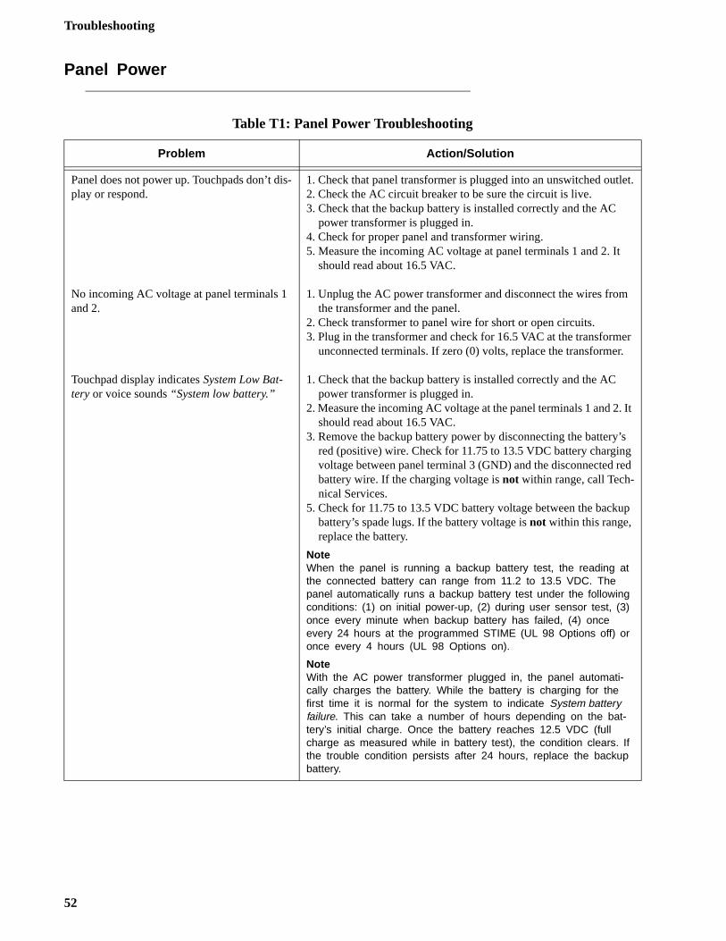
Troubleshooting
et.
r
It
s d
p
Panel Power
Table T1: Panel Power Troubleshooting
Problem Action/Solution
Panel does not power up. Touchpads don’t dis-play or respond.
No incoming AC voltage at panel terminals 1 and 2.
Touchpad display indicates System Low Bat-tery or voice sounds “System low battery.”
1. Check that panel transformer is plugged into an unswitched outl2. Check the AC circuit breaker to be sure the circuit is live.3. Check that the backup battery is installed correctly and the AC
power transformer is plugged in.4. Check for proper panel and transformer wiring.5. Measure the incoming AC voltage at panel terminals 1 and 2. It
should read about 16.5 VAC.
1. Unplug the AC power transformer and disconnect the wires fromthe transformer and the panel.
2. Check transformer to panel wire for short or open circuits.3. Plug in the transformer and check for 16.5 VAC at the transforme
unconnected terminals. If zero (0) volts, replace the transformer.
1. Check that the backup battery is installed correctly and the AC power transformer is plugged in.
2. Measure the incoming AC voltage at the panel terminals 1 and 2.should read about 16.5 VAC.
3. Remove the backup battery power by disconnecting the battery’red (positive) wire. Check for 11.75 to 13.5 VDC battery chargingvoltage between panel terminal 3 (GND) and the disconnected rebattery wire. If the charging voltage is not within range, call Tech-nical Services.
5. Check for 11.75 to 13.5 VDC battery voltage between the backubattery’s spade lugs. If the battery voltage is not within this range, replace the battery.
NoteWhen the panel is running a backup battery test, the reading at the connected battery can range from 11.2 to 13.5 VDC. The panel automatically runs a backup battery test under the following conditions: (1) on initial power-up, (2) during user sensor test, (3) once every minute when backup battery has failed, (4) once every 24 hours at the programmed STIME (UL 98 Options off) or once every 4 hours (UL 98 Options on).
NoteWith the AC power transformer plugged in, the panel automati-cally charges the battery. While the battery is charging for the first time it is normal for the system to indicate System battery failure. This can take a number of hours depending on the bat-tery’s initial charge. Once the battery reaches 12.5 VDC (full charge as measured while in battery test), the condition clears. If the trouble condition persists after 24 hours, replace the backup battery.
52
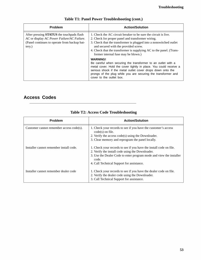
Troubleshooting
ler
Access Codes
After pressing STATUS the touchpads flash AC or display AC Power Failure/AC Failure. (Panel continues to operate from backup bat-tery.)
1. Check the AC circuit breaker to be sure the circuit is live.2. Check for proper panel and transformer wiring. 3. Check that the transformer is plugged into a nonswitched outlet
and secured with the provided screw.4. Check that the transformer is supplying AC to the panel. (Trans-
former internal fuse may be blown.)
WARNING!Be careful when securing the transformer to an outlet with a metal cover. Hold the cover tightly in place. You could receive a serious shock if the metal outlet cover drops down onto the prongs of the plug while you are securing the transformer and cover to the outlet box.
Table T2: Access Code Troubleshooting
Problem Action/Solution
Customer cannot remember access code(s).
Installer cannot remember install code.
Installer cannot remember dealer code
1. Check your records to see if you have the customer’s access code(s) on file.
2. Verify the access code(s) using the Downloader.3. Clear memory and reprogram the panel locally.
1. Check your records to see if you have the install code on file.2. Verify the install code using the Downloader.3. Use the Dealer Code to enter program mode and view the instal
code.4. Call Technical Support for assistance.
1. Check your records to see if you have the dealer code on file.2. Verify the dealer code using the Downloader.3. Call Technical Support for assistance.
Table T1: Panel Power Troubleshooting (cont.)
Problem Action/Solution
53
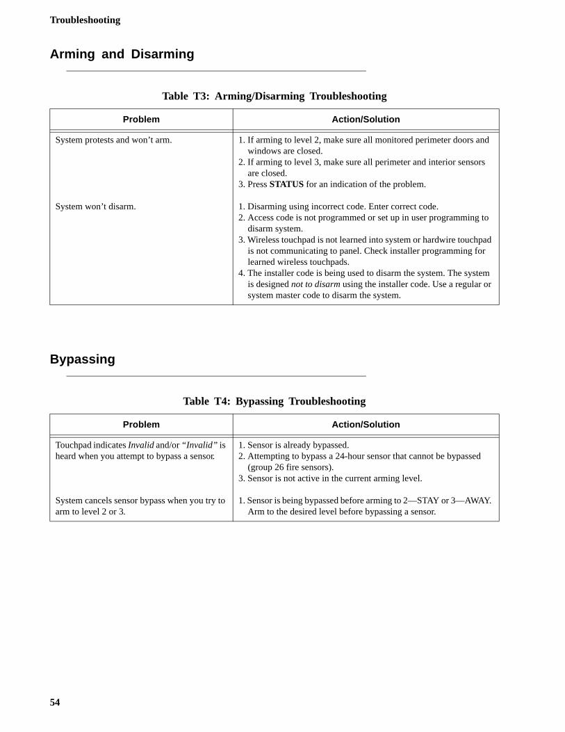
Troubleshooting
d
to
ad
m
.
Arming and Disarming
Bypassing
Table T3: Arming/Disarming Troubleshooting
Problem Action/Solution
System protests and won’t arm.
System won’t disarm.
1. If arming to level 2, make sure all monitored perimeter doors anwindows are closed.
2. If arming to level 3, make sure all perimeter and interior sensorsare closed.
3. Press STATUS for an indication of the problem.
1. Disarming using incorrect code. Enter correct code.2. Access code is not programmed or set up in user programming
disarm system.3. Wireless touchpad is not learned into system or hardwire touchp
is not communicating to panel. Check installer programming for learned wireless touchpads.
4. The installer code is being used to disarm the system. The systeis designed not to disarm using the installer code. Use a regular orsystem master code to disarm the system.
Table T4: Bypassing Troubleshooting
Problem Action/Solution
Touchpad indicates Invalid and/or “Invalid” is heard when you attempt to bypass a sensor.
System cancels sensor bypass when you try to arm to level 2 or 3.
1. Sensor is already bypassed.2. Attempting to bypass a 24-hour sensor that cannot be bypassed
(group 26 fire sensors).3. Sensor is not active in the current arming level.
1. Sensor is being bypassed before arming to 2—STAY or 3—AWAYArm to the desired level before bypassing a sensor.
54
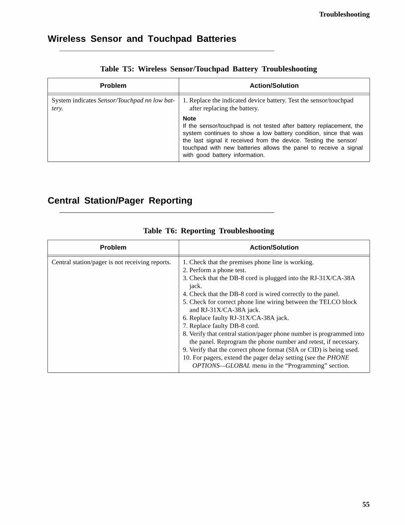
Troubleshooting
to y.
Wireless Sensor and Touchpad Batteries
Central Station/Pager Reporting
Table T5: Wireless Sensor/Touchpad Battery Troubleshooting
Problem Action/Solution
System indicates Sensor/Touchpad nn low bat-tery.
1. Replace the indicated device battery. Test the sensor/touchpad after replacing the battery.
NoteIf the sensor/touchpad is not tested after battery replacement, the system continues to show a low battery condition, since that was the last signal it received from the device. Testing the sensor/touchpad with new batteries allows the panel to receive a signal with good battery information.
Table T6: Reporting Troubleshooting
Problem Action/Solution
Central station/pager is not receiving reports. 1. Check that the premises phone line is working.2. Perform a phone test.3. Check that the DB-8 cord is plugged into the RJ-31X/CA-38A
jack.4. Check that the DB-8 cord is wired correctly to the panel.5. Check for correct phone line wiring between the TELCO block
and RJ-31X/CA-38A jack.6. Replace faulty RJ-31X/CA-38A jack.7. Replace faulty DB-8 cord.8. Verify that central station/pager phone number is programmed in
the panel. Reprogram the phone number and retest, if necessar9. Verify that the correct phone format (SIA or CID) is being used.10. For pagers, extend the pager delay setting (see the PHONE
OPTIONS—GLOBAL menu in the “Programming” section.
55
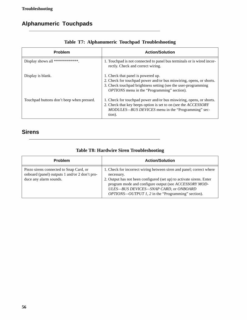
Troubleshooting
or-
ts.
ts.
re
r
Alphanumeric Touchpads
Sirens
Table T7: Alphanumeric Touchpad Troubleshooting
Problem Action/Solution
Display shows all ************.
Display is blank.
Touchpad buttons don’t beep when pressed.
1. Touchpad is not connected to panel bus terminals or is wired increctly. Check and correct wiring.
1. Check that panel is powered up.2. Check for touchpad power and/or bus miswiring, opens, or shor3. Check touchpad brightness setting (see the user-programming
OPTIONS menu in the “Programming” section).
1. Check for touchpad power and/or bus miswiring, opens, or shor2. Check that key beeps option is set to on (see the ACCESSORY
MODULES—BUS DEVICES menu in the “Programming” sec-tion).
Table T8: Hardwire Siren Troubleshooting
Problem Action/Solution
Piezo sirens connected to Snap Card, or onboard (panel) outputs 1 and/or 2 don’t pro-duce any alarm sounds.
1. Check for incorrect wiring between siren and panel; correct whenecessary.
2. Output has not been configured (set up) to activate sirens. Enteprogram mode and configure output (see ACCESSORY MOD-ULES—BUS DEVICES—SNAP CARD, or ONBOARD OPTIONS—OUTPUT 1, 2 in the “Programming” section).
56
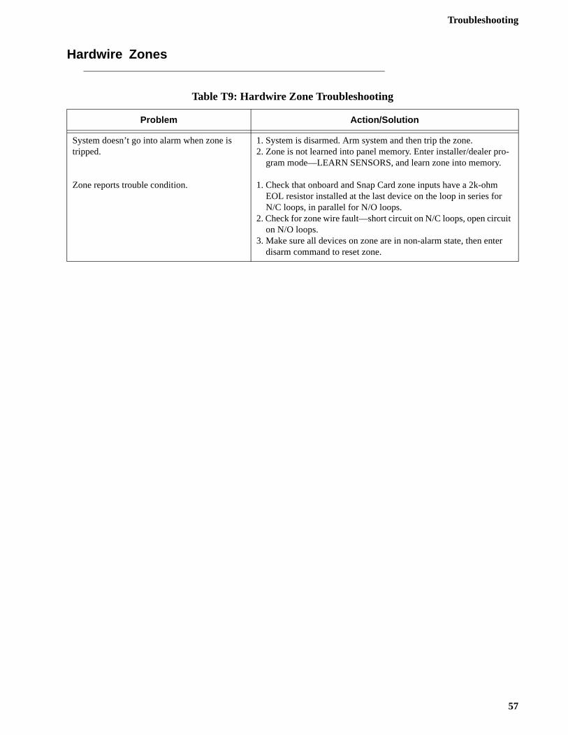
Troubleshooting
-
t
r
Hardwire Zones
Table T9: Hardwire Zone Troubleshooting
Problem Action/Solution
System doesn’t go into alarm when zone is tripped.
Zone reports trouble condition.
1. System is disarmed. Arm system and then trip the zone.2. Zone is not learned into panel memory. Enter installer/dealer pro
gram mode—LEARN SENSORS, and learn zone into memory.
1. Check that onboard and Snap Card zone inputs have a 2k-ohm EOL resistor installed at the last device on the loop in series forN/C loops, in parallel for N/O loops.
2. Check for zone wire fault—short circuit on N/C loops, open circuion N/O loops.
3. Make sure all devices on zone are in non-alarm state, then entedisarm command to reset zone.
57
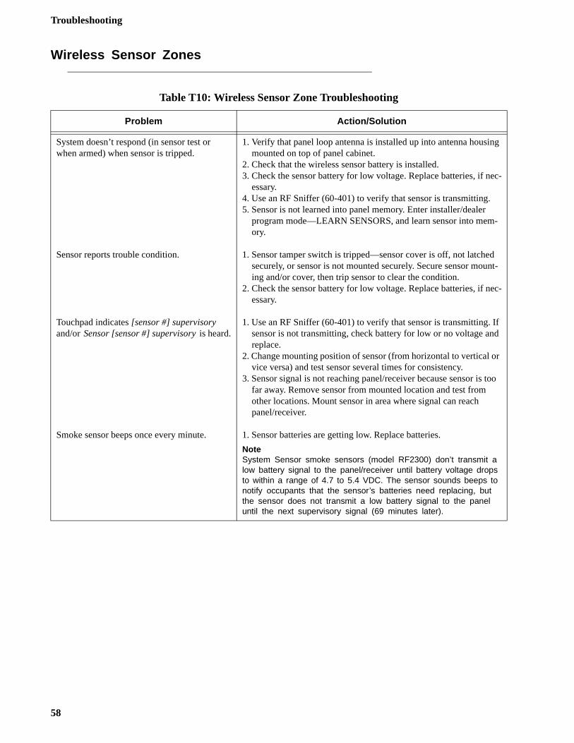
Troubleshooting
g
ec-
-
nt-
ec-
f d
r
oo
Wireless Sensor Zones
Table T10: Wireless Sensor Zone Troubleshooting
Problem Action/Solution
System doesn’t respond (in sensor test or when armed) when sensor is tripped.
Sensor reports trouble condition.
Touchpad indicates [sensor #] supervisory and/or Sensor [sensor #] supervisory is heard.
Smoke sensor beeps once every minute.
1. Verify that panel loop antenna is installed up into antenna housinmounted on top of panel cabinet.
2. Check that the wireless sensor battery is installed.3. Check the sensor battery for low voltage. Replace batteries, if n
essary.4. Use an RF Sniffer (60-401) to verify that sensor is transmitting.5. Sensor is not learned into panel memory. Enter installer/dealer
program mode—LEARN SENSORS, and learn sensor into memory.
1. Sensor tamper switch is tripped—sensor cover is off, not latchedsecurely, or sensor is not mounted securely. Secure sensor mouing and/or cover, then trip sensor to clear the condition.
2. Check the sensor battery for low voltage. Replace batteries, if nessary.
1. Use an RF Sniffer (60-401) to verify that sensor is transmitting. Isensor is not transmitting, check battery for low or no voltage anreplace.
2. Change mounting position of sensor (from horizontal to vertical ovice versa) and test sensor several times for consistency.
3. Sensor signal is not reaching panel/receiver because sensor is tfar away. Remove sensor from mounted location and test from other locations. Mount sensor in area where signal can reach panel/receiver.
1. Sensor batteries are getting low. Replace batteries.
NoteSystem Sensor smoke sensors (model RF2300) don’t transmit a low battery signal to the panel/receiver until battery voltage drops to within a range of 4.7 to 5.4 VDC. The sensor sounds beeps to notify occupants that the sensor’s batteries need replacing, but the sensor does not transmit a low battery signal to the panel until the next supervisory signal (69 minutes later).
58
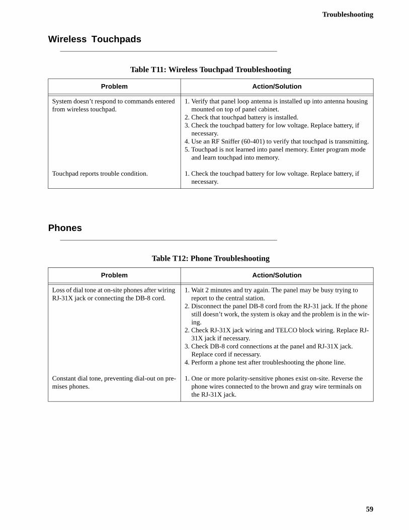
Troubleshooting
g
.e
e r-
-
Wireless Touchpads
Phones
Table T11: Wireless Touchpad Troubleshooting
Problem Action/Solution
System doesn’t respond to commands entered from wireless touchpad.
Touchpad reports trouble condition.
1. Verify that panel loop antenna is installed up into antenna housinmounted on top of panel cabinet.
2. Check that touchpad battery is installed.3. Check the touchpad battery for low voltage. Replace battery, if
necessary.4. Use an RF Sniffer (60-401) to verify that touchpad is transmitting5. Touchpad is not learned into panel memory. Enter program mod
and learn touchpad into memory.
1. Check the touchpad battery for low voltage. Replace battery, if necessary.
Table T12: Phone Troubleshooting
Problem Action/Solution
Loss of dial tone at on-site phones after wiring RJ-31X jack or connecting the DB-8 cord.
Constant dial tone, preventing dial-out on pre-mises phones.
1. Wait 2 minutes and try again. The panel may be busy trying to report to the central station.2. Disconnect the panel DB-8 cord from the RJ-31 jack. If the phon
still doesn’t work, the system is okay and the problem is in the wiing.
2. Check RJ-31X jack wiring and TELCO block wiring. Replace RJ31X jack if necessary.
3. Check DB-8 cord connections at the panel and RJ-31X jack. Replace cord if necessary.
4. Perform a phone test after troubleshooting the phone line.
1. One or more polarity-sensitive phones exist on-site. Reverse thephone wires connected to the brown and gray wire terminals on the RJ-31X jack.
59
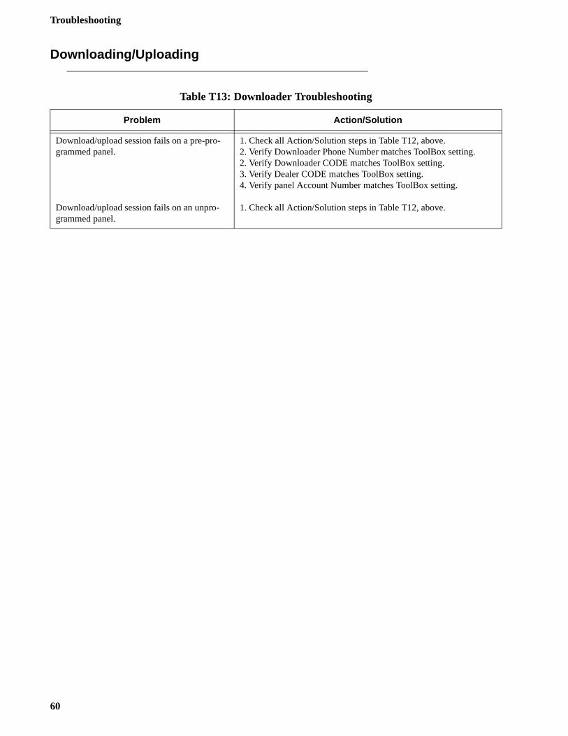
Troubleshooting
Downloading/Uploading
Table T13: Downloader Troubleshooting
Problem Action/Solution
Download/upload session fails on a pre-pro-grammed panel.
Download/upload session fails on an unpro-grammed panel.
1. Check all Action/Solution steps in Table T12, above.2. Verify Downloader Phone Number matches ToolBox setting.2. Verify Downloader CODE matches ToolBox setting.3. Verify Dealer CODE matches ToolBox setting.4. Verify panel Account Number matches ToolBox setting.
1. Check all Action/Solution steps in Table T12, above.
60
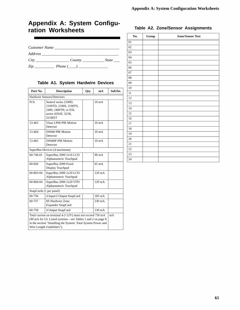
Appendix A: System Configuration Worksheets
Appendix A: System Configu-ration Worksheets
Customer Name _________________________________
Address _______________________________________
City _________________ County ___________ State ___
Zip __________ Phone (____) _______________
Table A1. System Hardwire Devices
Part No. Description Qty. mA SubTot.
Hardwire Sensors/Detectors
N/A Sentrol series 2100D, 2100TD, 2100S, 2100TS, 2400, 2400TH, or ESL series 429AT, 521B, 521BXT
10 mA
13-463 Visus LP60 PIR Motion Detector
10 mA
13-464 DS940 PIR MotionDetector
10 mA
13-465 DS940P PIR MotionDetector
10 mA
SuperBus Devices (4 maximum)
60-746-01 SuperBus 2000 2x16 LCD Alphanumeric Touchpad
90 mA
60-820 SuperBus 2000 FixedDisplay Touchpad
65 mA
60-803-04 SuperBus 2000 2x20 LCD Alphanumeric Touchpad
120 mA
60-804-04 SuperBus 2000 2x20 VFD Alphanumeric Touchpad
120 mA
SnapCards (1 per panel)
60-756 4 Input/2 Output SnapCard 185 mA
60-757 8Z Hardwire Zone Expander SnapCard
230 mA
60-758 4 Output SnapCard 130 mA
Total current on terminal 4 (+12V) must not exceed 750 mA (90 mA for UL Listed systems—see Tables 1 and 2 on page 8 in the section “Installing the System: Total System Power and Wire Length Guidelines”).
mA
Table A2. Zone/Sensor Assignments
No. Group Zone/Sensor Text
01
02
03
04
05
06
07
08
09
10
11
12
13
14
15
16
17
18
19
20
21
22
23
24
61
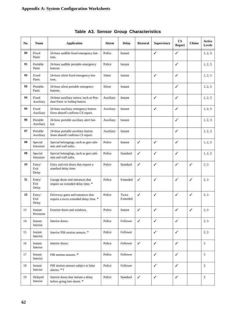
Appendix A: System Configuration Worksheets
Table A3. Sensor Group Characteristics
No. Name Application Alarm Delay Restoral SupervisoryCS
ReportChime
ActiveLevels
00 Fixed Panic
24-hour audible fixed emergency but-tons.
Police Instant ✓ ✓ 1, 2, 3
01 Portable Panic
24-hour audible portable emergency buttons.
Police Instant ✓ 1, 2, 3
02 Fixed Panic
24-hour silent fixed emergency but-tons.
Silent Instant ✓ ✓ 1, 2, 3
03 Portable Panic
24-hour silent portable emergency buttons.
Silent Instant ✓ 1, 2, 3
04 Fixed Auxiliary
24-hour auxiliary sensor, such as Pen-dant Panic or holdup button.
Auxiliary Instant ✓ ✓ 1, 2, 3
05 Fixed Auxiliary
24-hour auxiliary emergency button. Siren shutoff confirms CS report.
Auxiliary Instant ✓ ✓ 1, 2, 3
06 Portable Auxiliary
24-hour portable auxiliary alert but-ton.
Auxiliary Instant ✓ 1, 2, 3
07 Portable Auxiliary
24-hour portable auxiliary button. Siren shutoff confirms CS report.
Auxiliary Instant ✓ 1, 2, 3
08 Special Intrusion
Special belongings, such as gun cabi-nets and wall safes.
Police Instant ✓ ✓ ✓ 1, 2, 3
09 Special Intrusion
Special belongings, such as gun cabi-nets and wall safes.
Police Standard ✓ ✓ ✓ 1, 2, 3
10 Entry/Exit Delay
Entry and exit doors that require a standard delay time.
Police Standard ✓ ✓ ✓ ✓ 2, 3
11 Entry/Exit Delay
Garage doors and entrances that require an extended delay time. *
Police Extended ✓ ✓ ✓ ✓ 2, 3
12 Entry/Exit Delay
Driveway gates and entrances that require a twice extended delay time. *
Police TwiceExtended
✓ ✓ ✓ ✓ 2, 3
13 Instant Perimeter
Exterior doors and windows. Police Instant ✓ ✓ ✓ ✓ 2, 3
14 Instant Interior
Interior doors. Police Follower ✓ ✓ ✓ 2, 3
15 Instant Interior
Interior PIR motion sensors. * Police Follower ✓ ✓ 2, 3
16 Instant Interior
Interior doors. Police Follower ✓ ✓ ✓ 3
17 Instant Interior
PIR motion sensors. * Police Follower ✓ ✓ 3
18 Instant Interior
PIR motion sensors subject to false alarms. * †
Police Follower ✓ ✓ 3
19 Delayed Interior
Interior doors that initiate a delay before going into alarm. *
Police Standard ✓ ✓ ✓ 3
62
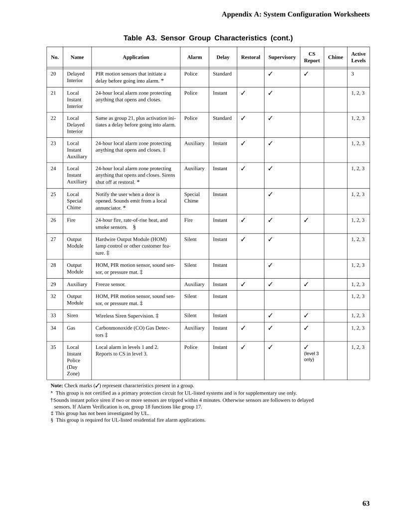
Appendix A: System Configuration Worksheets
20 Delayed Interior
PIR motion sensors that initiate a delay before going into alarm. *
Police Standard ✓ ✓ 3
21 Local Instant Interior
24-hour local alarm zone protecting anything that opens and closes.
Police Instant ✓ ✓ 1, 2, 3
22 Local Delayed Interior
Same as group 21, plus activation ini-tiates a delay before going into alarm.
Police Standard ✓ ✓ 1, 2, 3
23 Local Instant Auxiliary
24-hour local alarm zone protecting anything that opens and closes. ‡
Auxiliary Instant ✓ ✓ 1, 2, 3
24 Local Instant Auxiliary
24-hour local alarm zone protecting anything that opens and closes. Sirens shut off at restoral. *
Auxiliary Instant ✓ ✓ 1, 2, 3
25 Local Special Chime
Notify the user when a door is opened. Sounds emit from a local annunciator. *
Special Chime
Instant ✓ 1, 2, 3
26 Fire 24-hour fire, rate-of-rise heat, and smoke sensors. §
Fire Instant ✓ ✓ ✓ 1, 2, 3
27 Output Module
Hardwire Output Module (HOM) lamp control or other customer fea-ture. ‡
Silent Instant ✓ ✓ 1, 2, 3
28 Output Module
HOM, PIR motion sensor, sound sen-sor, or pressure mat. ‡
Silent Instant ✓ 1, 2, 3
29 Auxiliary Freeze sensor. Auxiliary Instant ✓ ✓ ✓ 1, 2, 3
32 Output Module
HOM, PIR motion sensor, sound sen-sor, or pressure mat. ‡
Silent Instant 1, 2, 3
33 Siren Wireless Siren Supervision. ‡ Silent Instant ✓ ✓ 1, 2, 3
34 Gas Carbonmonoxide (CO) Gas Detec-tors ‡
Auxiliary Instant ✓ ✓ ✓ 1, 2, 3
35 Local Instant Police (Day Zone)
Local alarm in levels 1 and 2.Reports to CS in level 3.
Police Instant ✓ ✓ ✓(level 3 only)
1, 2, 3
Note: Check marks (✓) represent characteristics present in a group.
* This group is not certified as a primary protection circuit for UL-listed systems and is for supplementary use only.† Sounds instant police siren if two or more sensors are tripped within 4 minutes. Otherwise sensors are followers to delayed sensors. If Alarm Verification is on, group 18 functions like group 17.‡ This group has not been investigated by UL.§ This group is required for UL-listed residential fire alarm applications.
Table A3. Sensor Group Characteristics (cont.)
No. Name Application Alarm Delay Restoral SupervisoryCS
ReportChime
ActiveLevels
63
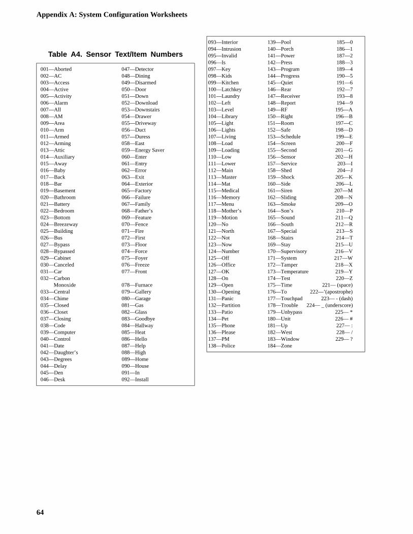
Appendix A: System Configuration Worksheets
Table A4. Sensor Text/Item Numbers
001—Aborted 047—Detector002—AC 048—Dining003—Access 049—Disarmed004—Active 050—Door005—Activity 051—Down006—Alarm 052—Download007—All 053—Downstairs008—AM 054—Drawer009—Area 055—Driveway010—Arm 056—Duct011—Armed 057—Duress012—Arming 058—East013—Attic 059—Energy Saver014—Auxiliary 060—Enter015—Away 061—Entry016—Baby 062—Error017—Back 063—Exit018—Bar 064—Exterior019—Basement 065—Factory020—Bathroom 066—Failure021—Battery 067—Family022—Bedroom 068—Father’s023—Bottom 069—Feature024—Breezeway 070—Fence025—Building 071—Fire026—Bus 072—First027—Bypass 073—Floor028—Bypassed 074—Force029—Cabinet 075—Foyer030—Canceled 076—Freeze031—Car 077—Front032—Carbon
Monoxide 078—Furnace033—Central 079—Gallery034—Chime 080—Garage035—Closed 081—Gas036—Closet 082—Glass037—Closing 083—Goodbye038—Code 084—Hallway039—Computer 085—Heat040—Control 086—Hello041—Date 087—Help042—Daughter’s 088—High043—Degrees 089—Home044—Delay 090—House045—Den 091—In046—Desk 092—Install
093—Interior 139—Pool 185—0094—Intrusion 140—Porch 186—1095—Invalid 141—Power 187—2096—Is 142—Press 188—3097—Key 143—Program 189—4098—Kids 144—Progress 190—5099—Kitchen 145—Quiet 191—6100—Latchkey 146—Rear 192—7101—Laundry 147—Receiver 193—8102—Left 148—Report 194—9103—Level 149—RF 195—A104—Library 150—Right 196—B105—Light 151—Room 197—C106—Lights 152—Safe 198—D107—Living 153—Schedule 199—E108—Load 154—Screen 200—F109—Loading 155—Second 201—G110—Low 156—Sensor 202—H111—Lower 157—Service 203—I112—Main 158—Shed 204—J113—Master 159—Shock 205—K114—Mat 160—Side 206—L115—Medical 161—Siren 207—M116—Memory 162—Sliding 208—N117—Menu 163—Smoke 209—O118—Mother’s 164—Son’s 210—P119—Motion 165—Sound 211—Q120—No 166—South 212—R121—North 167—Special 213—S122—Not 168—Stairs 214—T123—Now 169—Stay 215—U124—Number 170—Supervisory 216—V125—Off 171—System 217—W126—Office 172—Tamper 218—X127—OK 173—Temperature 219—Y128—On 174—Test 220—Z129—Open 175—Time 221— (space)130—Opening 176—To 222—’(apostrophe)131—Panic 177—Touchpad 223— - (dash)132—Partition 178—Trouble 224— _ (underscore)133—Patio 179—Unbypass 225— *134—Pet 180—Unit 226— #135—Phone 181—Up 227— :136—Please 182—West 228— /137—PM 183—Window 229— ?138—Police 184—Zone
64
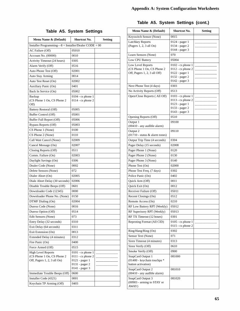
Appendix A: System Configuration Worksheets
Table A5. System Settings
Menu Name & (Default) Shortcut No. Setting
Installer Programming—8 + Installer/Dealer CODE + 00
AC Failure (Off) 05010
Account No. (00000) 0010
Activity Timeout (24 hours) 0305
Alarm Verify (Off) 0516
Auto Phone Test (Off) 02001
Auto Stay Arming 0014
Auto Test Reset (On) 02002
Auxiliary Panic (On) 0401
Back In Service (On) 05002
Backup(CS Phone 1 On, CS Phone 2 Off)
0104 - cs phone 10114 - cs phone 2
Battery Restoral (Off) 05005
Buffer Control (Off) 05001
Buffer Full Report (Off) 05006
Bypass Reports (Off) 05003
CS Phone 1 (None) 0100
CS Phone 2 (None) 0110
Call Wait Cancel (None) 02009
Cancel Message (On) 02007
Closing Reports (Off) 0511
Comm. Failure (On) 02003
Daylight Savings (On) 0306
Dealer Code (None) 0002
Delete Sensors (None) 072
Dialer Abort (On) 02005
Diale Abort Delay (30 seconds) 02006
Disable Trouble Beeps (Off) 0601
Downloader Code (12345) 0000
Downloader Phone No. (None) 0150
DTMF Dialing (On) 02004
Duress Code (None) 0016
Duress Option (Off) 0514
Edit Sensors (None) 073
Entry Delay (32 seconds) 0310
Exit Delay (64 seconds) 0311
Exit Extension (On) 0013
Extended Delay (4 minutes) 0312
Fire Panic (On) 0400
Force Armed (Off) 0515
High Level Reports(CS Phone 1 On, CS Phone 2 Off, Pagers 1, 2, 3 all On)
0101 - cs phone 10111 - cs phone 20121 - pager 10131 - pager 20141 - pager 3
________________________________________________________
Immediate Trouble Beeps (Off) 0600
Installer Code (4321) 0001
Keychain TP Arming (Off) 0403
Keyswitch Sensor (None) 0015
Latchkey Reports(Pagers 1, 2, 3 all On)
0124 - pager 10134 - pager 20144 - pager 3
____________________________
Learn Sensors (None) 070
Low CPU Battery 05004
Low Level Reports(CS Phone 1 On, CS Phone 2 Off, Pagers 1, 2, 3 all Off)
0102 - cs phone 10112 - cs phone 20122 - pager 10132 - pager 20142 - pager 3
________________________________________________________
Next Phone Test (4 days) 0303
No Activity Reports (Off) 0513
Open/Close Reports ( All Off) 0103 - cs phone 10113 - cs phone 20123 - pager 10133 - pager 20143 - pager 3
________________________________________________________
Opening Reports (Off) 0510
Output 1(00410 - any audible alarm)
09100
Output 2(01710 - status & alarm tones)
09110
Output Trip Time (4 seconds) 0304
Pager Delay (15 seconds) 02008
Pager Phone 1 (None) 0120
Pager Phone 2 (None) 0130
Pager Phone 3 (None) 0140
Phone Test (On) 02000
Phone Test Freq. (7 days) 0302
Police Panic (On) 0402
Quick Arm (Off) 0011
Quick Exit (On) 0012
Receiver Failure (Off) 05011
Recent Closings (On) 0512
Remote Access (On) 0210
RF Low Battery RPT (Weekly) 05012
RF Superisory RPT (Weekly) 05013
RF TX Timeout (12 hours) 0301
Reproting Format (All CID) 0105 - cs phone 10115 - cs phone 2
______________
Ring/Hang/Ring (On) 0302
Sensor Text (None) 071
Siren Timeout (4 minutes) 0313
Siren Verify (Off) 0610
Smoke Verify (Off) 0900
SnapCard Output 1(01400 - keychain touchpa * button activation)
081000
SnapCard Output 2(00410 - any audible alarm)
081010
SnapCard Output 3(00903 - arming to STAY or AWAY)
081020
Table A5. System Settings (cont.)
Menu Name & (Default) Shortcut No. Setting
65
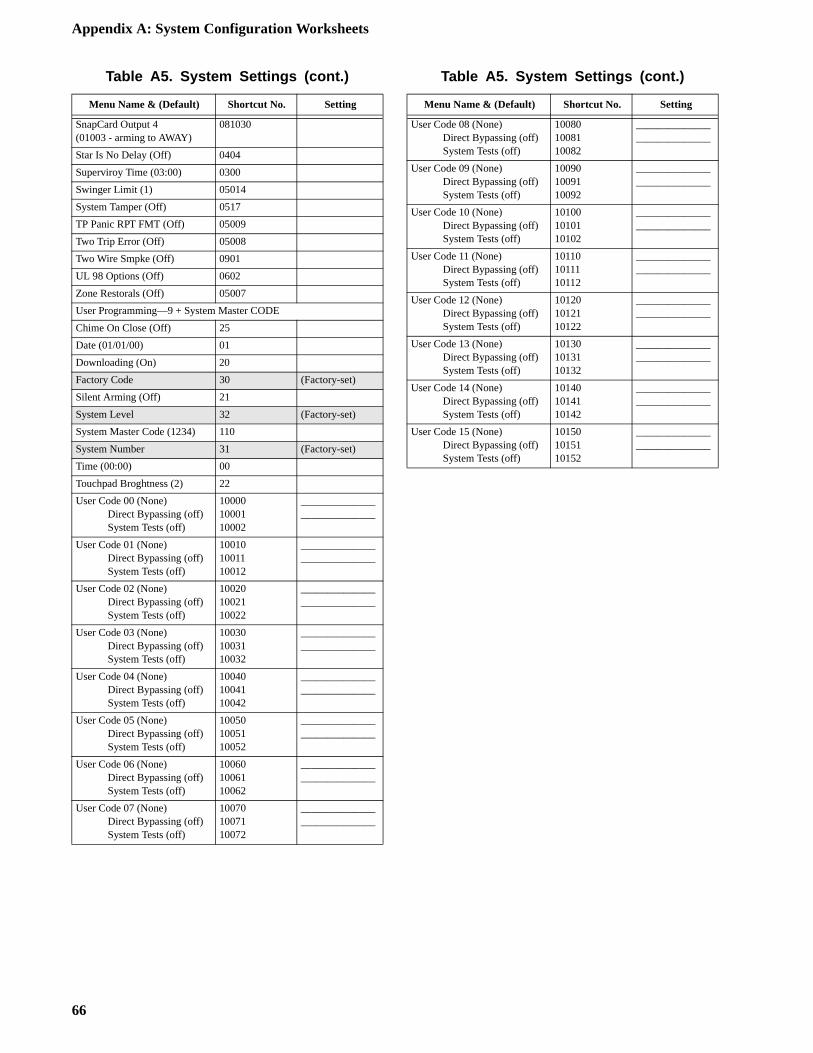
Appendix A: System Configuration Worksheets
SnapCard Output 4(01003 - arming to AWAY)
081030
Star Is No Delay (Off) 0404
Superviroy Time (03:00) 0300
Swinger Limit (1) 05014
System Tamper (Off) 0517
TP Panic RPT FMT (Off) 05009
Two Trip Error (Off) 05008
Two Wire Smpke (Off) 0901
UL 98 Options (Off) 0602
Zone Restorals (Off) 05007
User Programming—9 + System Master CODE
Chime On Close (Off) 25
Date (01/01/00) 01
Downloading (On) 20
Factory Code 30 (Factory-set)
Silent Arming (Off) 21
System Level 32 (Factory-set)
System Master Code (1234) 110
System Number 31 (Factory-set)
Time (00:00) 00
Touchpad Broghtness (2) 22
User Code 00 (None)Direct Bypassing (off)System Tests (off)
100001000110002
____________________________
User Code 01 (None)Direct Bypassing (off)System Tests (off)
100101001110012
____________________________
User Code 02 (None)Direct Bypassing (off)System Tests (off)
100201002110022
____________________________
User Code 03 (None)Direct Bypassing (off)System Tests (off)
100301003110032
____________________________
User Code 04 (None)Direct Bypassing (off)System Tests (off)
100401004110042
____________________________
User Code 05 (None)Direct Bypassing (off)System Tests (off)
100501005110052
____________________________
User Code 06 (None)Direct Bypassing (off)System Tests (off)
100601006110062
____________________________
User Code 07 (None)Direct Bypassing (off)System Tests (off)
100701007110072
____________________________
Table A5. System Settings (cont.)
Menu Name & (Default) Shortcut No. Setting
User Code 08 (None)Direct Bypassing (off)System Tests (off)
100801008110082
____________________________
User Code 09 (None)Direct Bypassing (off)System Tests (off)
100901009110092
____________________________
User Code 10 (None)Direct Bypassing (off)System Tests (off)
101001010110102
____________________________
User Code 11 (None)Direct Bypassing (off)System Tests (off)
101101011110112
____________________________
User Code 12 (None)Direct Bypassing (off)System Tests (off)
101201012110122
____________________________
User Code 13 (None)Direct Bypassing (off)System Tests (off)
101301013110132
____________________________
User Code 14 (None)Direct Bypassing (off)System Tests (off)
101401014110142
____________________________
User Code 15 (None)Direct Bypassing (off)System Tests (off)
101501015110152
____________________________
Table A5. System Settings (cont.)
Menu Name & (Default) Shortcut No. Setting
66
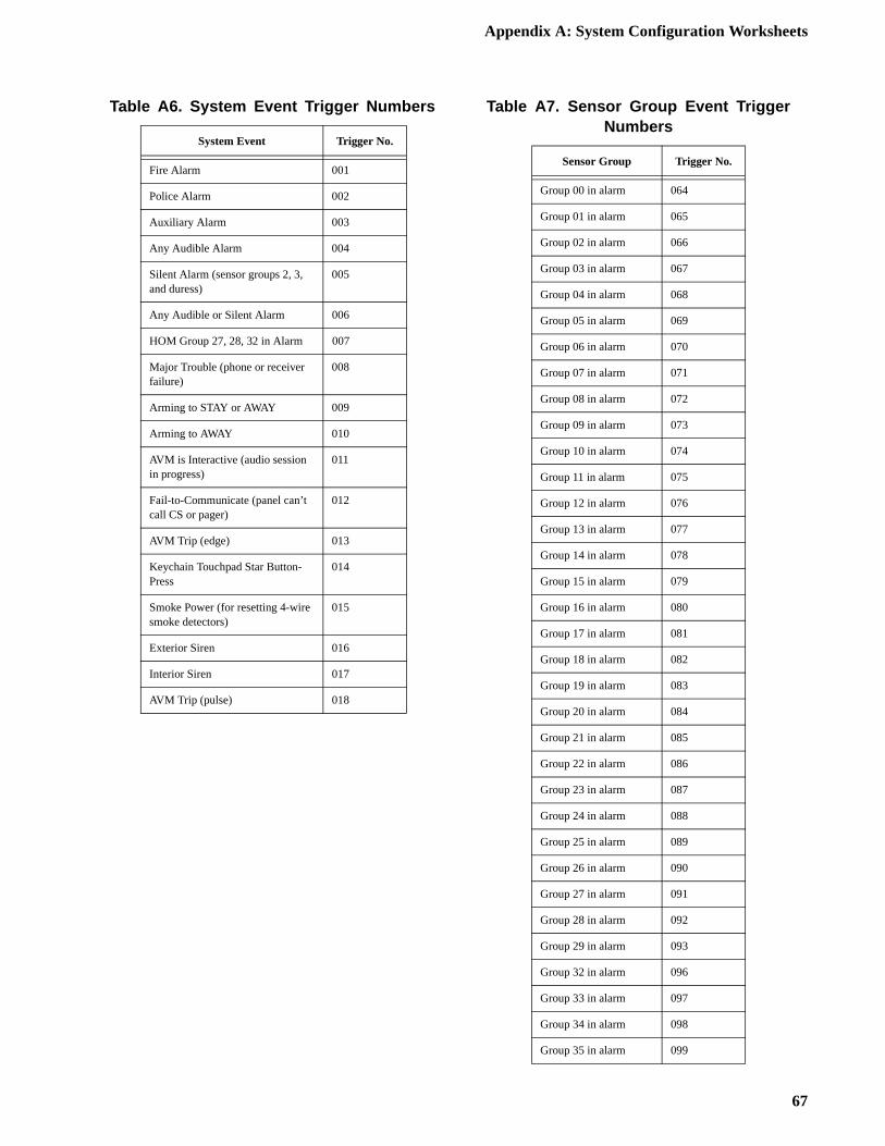
Appendix A: System Configuration Worksheets
Table A6. System Event Trigger Numbers
System Event Trigger No.
Fire Alarm 001
Police Alarm 002
Auxiliary Alarm 003
Any Audible Alarm 004
Silent Alarm (sensor groups 2, 3, and duress)
005
Any Audible or Silent Alarm 006
HOM Group 27, 28, 32 in Alarm 007
Major Trouble (phone or receiver failure)
008
Arming to STAY or AWAY 009
Arming to AWAY 010
AVM is Interactive (audio session in progress)
011
Fail-to-Communicate (panel can’t call CS or pager)
012
AVM Trip (edge) 013
Keychain Touchpad Star Button-Press
014
Smoke Power (for resetting 4-wire smoke detectors)
015
Exterior Siren 016
Interior Siren 017
AVM Trip (pulse) 018
Table A7. Sensor Group Event Trigger Numbers
Sensor Group Trigger No.
Group 00 in alarm 064
Group 01 in alarm 065
Group 02 in alarm 066
Group 03 in alarm 067
Group 04 in alarm 068
Group 05 in alarm 069
Group 06 in alarm 070
Group 07 in alarm 071
Group 08 in alarm 072
Group 09 in alarm 073
Group 10 in alarm 074
Group 11 in alarm 075
Group 12 in alarm 076
Group 13 in alarm 077
Group 14 in alarm 078
Group 15 in alarm 079
Group 16 in alarm 080
Group 17 in alarm 081
Group 18 in alarm 082
Group 19 in alarm 083
Group 20 in alarm 084
Group 21 in alarm 085
Group 22 in alarm 086
Group 23 in alarm 087
Group 24 in alarm 088
Group 25 in alarm 089
Group 26 in alarm 090
Group 27 in alarm 091
Group 28 in alarm 092
Group 29 in alarm 093
Group 32 in alarm 096
Group 33 in alarm 097
Group 34 in alarm 098
Group 35 in alarm 099
67
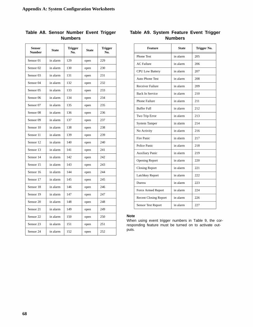
Appendix A: System Configuration Worksheets
NoteWhen using event trigger numbers in Table 9, the cor-responding feature must be turned on to activate out-puts.
Table A8. Sensor Number Event Trigger Numbers
Sensor Number
StateTrigger
No.State
Trigger No.
Sensor 01 in alarm 129 open 229
Sensor 02 in alarm 130 open 230
Sensor 03 in alarm 131 open 231
Sensor 04 in alarm 132 open 232
Sensor 05 in alarm 133 open 233
Sensor 06 in alarm 134 open 234
Sensor 07 in alarm 135 open 235
Sensor 08 in alarm 136 open 236
Sensor 09 in alarm 137 open 237
Sensor 10 in alarm 138 open 238
Sensor 11 in alarm 139 open 239
Sensor 12 in alarm 140 open 240
Sensor 13 in alarm 141 open 241
Sensor 14 in alarm 142 open 242
Sensor 15 in alarm 143 open 243
Sensor 16 in alarm 144 open 244
Sensor 17 in alarm 145 open 245
Sensor 18 in alarm 146 open 246
Sensor 19 in alarm 147 open 247
Sensor 20 in alarm 148 open 248
Sensor 21 in alarm 149 open 249
Sensor 22 in alarm 150 open 250
Sensor 23 in alarm 151 open 251
Sensor 24 in alarm 152 open 252
Table A9. System Feature Event Trigger Numbers
Feature State Trigger No.
Phone Test in alarm 205
AC Failure in alarm 206
CPU Low Battery in alarm 207
Auto Phone Test in alarm 208
Receiver Failure in alarm 209
Back In Service in alarm 210
Phone Failure in alarm 211
Buffer Full in alarm 212
Two Trip Error in alarm 213
System Tamper in alarm 214
No Activity in alarm 216
Fire Panic in alarm 217
Police Panic in alarm 218
Auxiliary Panic in alarm 219
Opening Report in alarm 220
Closing Report in alarm 221
Latchkey Report in alarm 222
Duress in alarm 223
Force Armed Report in alarm 224
Recent Closing Report in alarm 226
Sensor Test Report in alarm 227
68
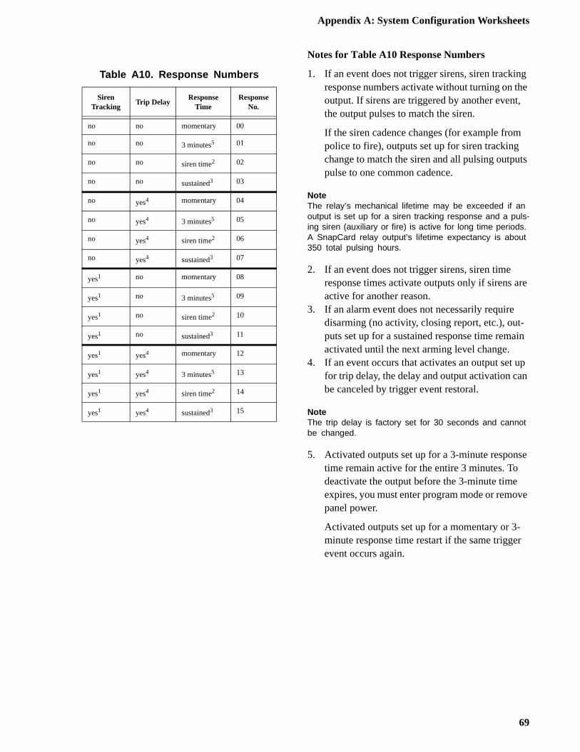
Appendix A: System Configuration Worksheets
g e
,
ts
re
in
up n
se
ve
r
Notes for Table A10 Response Numbers
1. If an event does not trigger sirens, siren trackinresponse numbers activate without turning on thoutput. If sirens are triggered by another eventthe output pulses to match the siren.
If the siren cadence changes (for example frompolice to fire), outputs set up for siren tracking change to match the siren and all pulsing outpupulse to one common cadence.
NoteThe relay’s mechanical lifetime may be exceeded if an output is set up for a siren tracking response and a puls-ing siren (auxiliary or fire) is active for long time periods. A SnapCard relay output’s lifetime expectancy is about 350 total pulsing hours.
2. If an event does not trigger sirens, siren time response times activate outputs only if sirens aactive for another reason.
3. If an alarm event does not necessarily require disarming (no activity, closing report, etc.), out-puts set up for a sustained response time remaactivated until the next arming level change.
4. If an event occurs that activates an output set for trip delay, the delay and output activation cabe canceled by trigger event restoral.
NoteThe trip delay is factory set for 30 seconds and cannot be changed.
5. Activated outputs set up for a 3-minute respontime remain active for the entire 3 minutes. To deactivate the output before the 3-minute time expires, you must enter program mode or remopanel power.
Activated outputs set up for a momentary or 3-minute response time restart if the same triggeevent occurs again.
Table A10. Response Numbers
Siren Tracking
Trip DelayResponse
TimeResponse
No.
no no momentary 00
no no 3 minutes5 01
no no siren time2 02
no no sustained3 03
no yes4 momentary 04
no yes4 3 minutes5 05
no yes4 siren time2 06
no yes4 sustained3 07
yes1 no momentary 08
yes1 no 3 minutes5 09
yes1 no siren time2 10
yes1 no sustained3 11
yes1 yes4 momentary 12
yes1 yes4 3 minutes5 13
yes1 yes4 siren time2 14
yes1 yes4 sustained3 15
69

Appendix A: System Configuration Worksheets
70
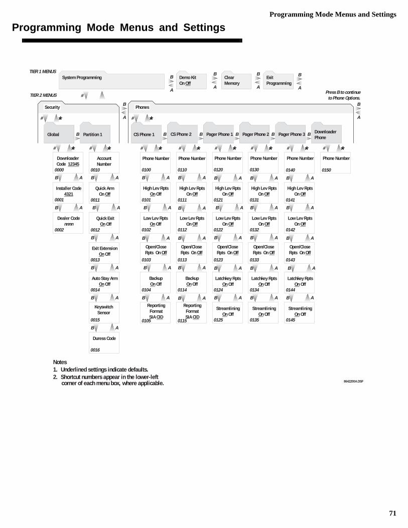
Programming Mode Menus and Settings
Programming Mode Menus and Settings
BB BBBB
# *# *
A
B
# *
B AB A
# *
# *
TIER 2 MENUS
Global
B A
B AB A
B AB A
Exit ExtensionOn Off
Installer Code4321
Quick ArmOn Off
Dealer Codennnn
Quick Exit On Off
Account Number
0001
0002 0012
0011
0010
0013
B A
B A
Duress Code
Keyswitch Sensor
0015
0016
Partition 1
B A
B A
B AB A
B AB A
B AB A
B AB A
B AB A
Phone Number
High Lev RptsOn Off
BackupOn Off
Low Lev RptsOn Off
Latchkey RptsOn Off
0100
Phone Number
0110
0101
High Lev RptsOn Off
0111
Low Lev RptsOn Off
0102 0112
Phone Number Phone Number
0120 0130
0121
High Lev RptsOn Off
0131
High Lev RptsOn Off
Low Lev RptsOn Off
0122
Low Lev RptsOn Off
0132
0113 0103
Open/Close Rpts On Off
Open/Close Rpts On Off
BackupOn Off
0114 0104
ReportingFormatSIA CID
0115 0105
0124
Latchkey RptsOn Off
0134
Latchkey RptsOn Off
0144
Open/Close Rpts On Off
Open/Close Rpts On Off
Open/Close Rpts On Off
0123 0133 0143
Low Lev RptsOn Off
0142
High Lev RptsOn Off
0141
0140
Phone Number
0150
Phone Number
StreamliningOn Off
0125
StreamliningOn Off
0135
StreamliningOn Off
0145
Phones
CS Phone 1
Downloader Code 12345
0000
CS Phone 2
# *
Pager Phone 1
B A
B A
# *
Pager Phone 2
B A
B A
B A
B A
B A
# *
Pager Phone 3
B A
B A
B A
B A
# *
DownloaderPhone
# * Security
Auto Stay ArmOn Off
0014
B A
#A
B
A
B
A
BTIER 1 MENUS
A
B
Notes1. Underlined settings indicate defaults.2. Shortcut numbers appear in the lower-left
corner of each menu box, where applicable.
Press B to continue to Phone Options.
A
B
System Programming Demo Kit On Off
ClearMemory
Exit Programming
ReportingFormatSIA CID
8642200A.DSF
71
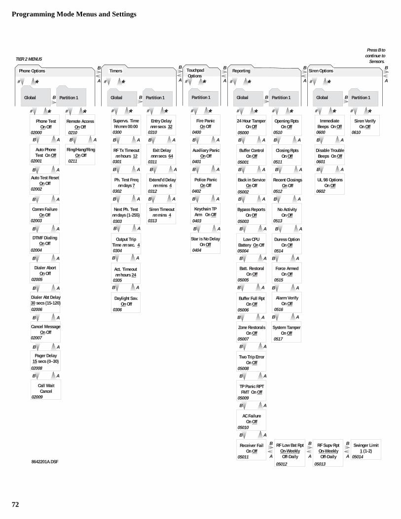
Programming Mode Menus and Settings
B A B A
B A B A
B A
B A
B A
B A B A
RF Supv RptOn-WeeklyOff-Daily
RF Low Bat RptOn-WeeklyOff-Daily
05012 05013
B A
Swinger Limit1 (1-2)
05014
B A
# *# *
B A
B AB A
B AB A
No ActivityOn Off
Buffer ControlOn Off
Closing RptsOn Off
Back in ServiceOn Off
Recent ClosingsOn Off
Opening RptsOn Off
05001
05002 0512
0511
0510
0513
24 Hour TamperOn Off
05000
Bypass ReportsOn Off
05003
B A
Buffer Full RptOn Off
05005
Low CPU Battery On Off
05004
05006
B A
Duress OptionOn Off
0514
Force ArmedOn Off
0515
Batt. RestoralOn Off
Alarm VerifyOn Off
0516
System TamperOn Off
0517
Zone RestoralsOn Off
05007
Two Trip ErrorOn Off
05008
TP Panic RPTFMT On Off
05009
AC FailureOn Off
05010
Receiver FailOn Off
05011 A
B
A
B
Press B to continue to
Sensors.
# *
B A
# *
B A
B AB A
Comm FailureOn Off
DTMF DialingOn Off
Phone TestOn Off
Remote AccessOn Off
Auto PhoneTest On Off
Ring/Hang/RingOn Off
Dialer AbortOn Off
Pager Delay15 secs (0–30)
02000
02003
02001
02005
02008
0210
0211
B A
Auto Test ResetOn Off
02002
Dialer Abt Delay30 secs (15-120) 02006
B A
Cancel MessageOn Off
02007
Call WaitCancel
02009
B A
B A
02004
B A
B A
A
B
B
# *Global Partition 1
Timers
B A
# *# *
B A
B AB A
B AB A
Siren Timeoutnn mins 4
RF Tx Timeoutnn hours 12
Exit Delaynnn secs 64
Ph. Test Freqnn days 7
Extend'd Delay nn mins 4
Entry Delaynnn secs 32
0301
0302 0312
0311
0310
0313
Supervs. Timehh:mm 00:00
0300
Next Ph. Testnn days (1-255) 0303
B A
B A
Daylight Sav.On Off
Act. Timeoutnn hours 24
0305
Output TripTime nn sec. 4 0304
B A
0306
B A
# *
# *Partition 1
B A
B A
Auxiliary PanicOn Off
Police PanicOn Off
0401
0402
Fire PanicOn Off
0400
Touchpad Options
Keychain TP Arm On Off
0403
B A
Star is No DelayOn Off
0404
A
B
B
# *Global Partition 1
Reporting
A
B
# *# *
A
B
B
# *Global
B A
B A
Disable TroubleBeeps On Off
UL 98 OptionsOn Off
Siren VerifyOn Off
0601
0602
0610
Partition 1
Immediate Beeps On Off
0600
Siren Options
8642201A.DSF
# * Phone Options
BGlobal Partition 1
TIER 2 MENUS
A
B
A
B
72
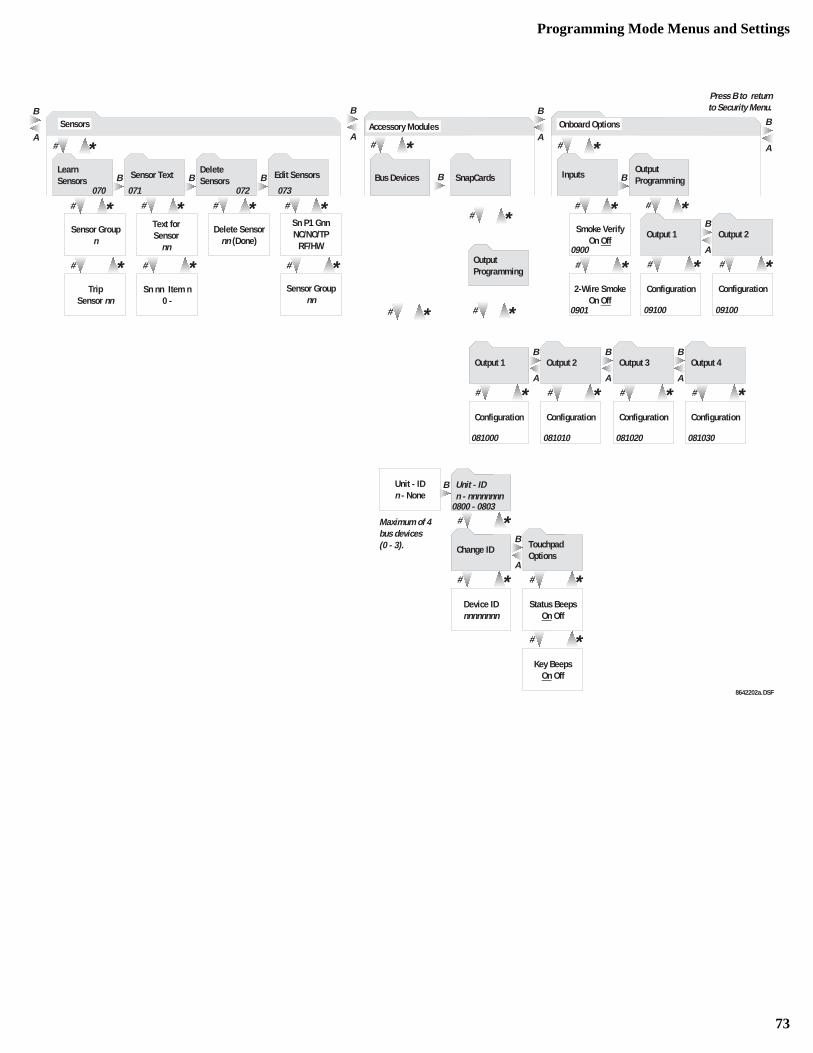
Programming Mode Menus and Settings
# *
# *
# *
# *
# *# * # *
BBB
# *A
B
# *
B
# *
B
# *Smoke Verify
On Off
2-Wire SmokeOn Off
# *Sn nn Item n
0 -
A
B
Maximum of 4bus devices(0 - 3).
Press B to returnto Security Menu.
A
B
Sensor Groupn
Text for Sensor
nn
Delete Sensornn (Done)
Sensors
Learn Sensors
Delete Sensors
Edit Sensors
# *
Trip Sensor nn
070
Sensor Text
071
# *
072 073
Sensor Groupnn
# *
Bus Devices
# * Accessory Modules
Unit - IDn - None
Status BeepsOn Off
Device IDnnnnnnnn
Unit - IDn - nnnnnnnn
Change ID TouchpadOptions
SnapCards
OutputProgramming
Key BeepsOn Off
A
B
# * # *
B
A
B
Inputs
# *Output Programming
Onboard Options
0800 - 0803
0900
0901
Sn P1 GnnNC/NO/TP
RF/HW
# *
# *A
B
# *ConfigurationConfiguration
Output 1 Output 2
# *A
B
# *ConfigurationConfiguration
Output 1 Output 2
081000 081010
# *A
B
# *ConfigurationConfiguration
Output 3 Output 4
081020 081030
09100 09100
A
B
8642202a.DSF
73

Programming Mode Menus and Settings
9 10
ZONE1 ZCOM
P A N E LT E R M I N A L S
8
OUT2/OC
+
COM. . . . . . . .+ - -
COM
NONO
M O D E L4 4 9 A T
+
COM. . . . . . . .+ - -
COM
NONO
M O D E L4 4 9 A T
2k OhmEOL RESISTOR
49-454(LOCATE AT LAST
DETECTOR)
4
+12V
7
PIR MOTIONSENSOR (DS940/P)
2k Ohm EOLRESISTOR 49-454(LOCATE AT LASTDEVICE)
BLA
CK
WH
ITE
GR
EE
N
RE
D
1 2 3 4 5 6 10 11 12 13 14 15 16 17 18 19 20 21
16.5 VAC
+12V(750 mA;
90 mA UL) A B ZCOMGNDZONE
2ZONE
3 ZCOMZCOM/2W -
ZONE4
ZONE5 GRY
Z6/2W + BRN RED
CLASS II POWERTRANSFORMER (60-822)
TO UNSWITCHED ACPOWER RECEPTACLE
(24HR)
NORMALLYOPEN (N/O)
CONTACTSIN PARALLEL
NORMALLYCLOSED
(N/C)CONTACTSIN SERIES
+-
ZONE 62-WIRE SMOKE
DETECTORCONNECTIONS.
+-
8 9
OUT1/+12V
ZONE1
RJ-31X PHONEJACK (CA-38AIN CANADA)
BRN GRY
GRN RED
RE
D
GR
EE
N
WHITE ORYELLOW
BLA
CK
TELCOPROTECTOR
BLOCK
GRN RED
TIP(+)
RING(-)
RJ-31XPHONE LINEWIRE RUN
GREEN RED
BLACK WHITE OR YELLOW
TO PREMISES PHONES
GR
EE
N
BR
OW
N
GR
AY
RE
D
2k Ohm EOLRESISTOR 49-454(LOCATE AT LASTDETECTOR)
DB-8CORDCLASS II
16.5 VAC25 VA
SUPERBUS 2000 2X16 LCDALPHANUMERIC TOUCHPAD(60-746-01) REQUIRED FORON-SITE PROGRAMMING.
FOR NORMAL OPERATION ANDUSER PROGRAMMING,
SUPERBUS 2000 FIXED ENGLISHTOUCHPAD MAY ALSO BE USED.
MAXIMUM OF 4 BUS DEVICES.
ALL PANEL TERMINAL CONNECTIONS ARE CLASS II POWER LIMITED
REDBLACK
HARDWIRE INTERIOR SIREN(13-374) MAXIMUM 150 mA.WHEN SET TO DEFAULT
CONFIGURATION NO. 00410,WHICH ACTIVATES THE OUTPUT
FOR ANY AUDIBLE ALARM,OUTPUT 1 PROVIDES UP TO
1.25 AMPS FOR NON-UL LISTED SYSTEMS(650 mA FOR UL LISTED SYSTEMS).
CONCORD EXPRESS SYSTEM WIRING DIAGRAM (60-806)
OUT2/OC GRNBUS
RED BLACK
4
+12V
INTERIOR PIEZO SIREN(30-006) MAXIMUM 10 mA.
OUTPUT 2 IS OPENCOLLECTOR THAT PROVIDES
UP TO 200 mA. DEFAULTCONFIGURATION NO. 01710
ACTIVATES OUTPUTFOR STATUS AND
ALARM TONES.
2-WIRE SMOKE SETTINGIN PROGRAMMINGMODE MUST BE ON.
DO NOT USETERMINAL 16 FORREGULAR ZONECOMMON CONNECTIONIF ZONE 6 IS SET UPFOR 2-WIRE SMOKEDETECTORS.
USE SYSTEMSENSOR MODELS2100D, 2100TD, 2100S,2100TS, 2400, 2400TH,OR ESL MODELS 429AT,521B, 521BXT (10 MAXIMUM).MODELS 521B AND 521BXTDIP SWITCHES MUST BESET AS FOLLOWS:1 - ON, 2 - OFF.
BLACK
RED
BACKUPBATTERY(60-681)12V, 4AH
WATER PIPEGROUND CLAMP
BATTERY
PIPE
PANEL EARTHGROUND CONNECTION
BATTERY TESTEDAUTOMATICALLYEVERY 24 HOURS(EVERY 4 HOURS WITH UL 98 OPTIONS SET TO ON). REPLACEONLY WITH EXACTREPLACEMENT.
SNAPCARD
HEADER
PROGRAMMINGTOUCHPAD HEADER
WARNING: HIGH VOLTAGE!DISCONNECT TELEPHONELINE AT TELCO JACKBEFORE SERVICING.
S t a t u s
F e a t u r e s
p r e s s b o t h
L i g h t s
S y s t e m
A w a y
P a g e r
O f f
N o D e l a yp r e s s b o t h
p r e s s b o t h
T e s t S y s t e m W e e k l y
S i l e n t
S t a y
D *
7
0 #
8
B
A
4
1
5 6
2 3
B y p a s s
M e n u
C 9
_ + NC C
3 4
+12VGND
2k Ohm EOL RESISTOR 49-454(LOCATE AT SIREN)
CONNECTION OF THE FIREALARM SIGNAL TO A FIREALARM HEADQUARTERS ORA CENTRAL STATION SHALLBE PERMITTED ONLY WITHTHE PERMISSION OF THELOCAL AUTHORITY HAVINGJURISDICTION. THE BURGLARALARM SIGNAL SHALL NOT BECONNECTED TO A POLICEEMERGENCY NUMBER.
8642G26B.DSF
PANEL TERMINAL 8 (OUT2/OC)MUST BE SET TO CONFIGURATIONNUMBER 01500 FOR CONNECTEDSMOKE DETECTORS TO RESETAFTER CANCELING A FIRE ALARM.
2k OhmRESISTOR49-454(LOCATE ATPANEL)
74

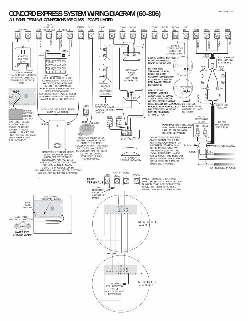
9 10
ZONE1 ZCOM
P A N E LT E R M I N A L S
8
OUT2/OC
+
COM. . . . . . . .+ - -
COM
NONO
M O D E L4 4 9 A T
+
COM. . . . . . . .+ - -
COM
NONO
M O D E L4 4 9 A T
2k OhmEOL RESISTOR
49-454(LOCATE AT LAST
DETECTOR)
4
+12V
7
PIR MOTIONSENSOR (DS940/P)
2k Ohm EOLRESISTOR 49-454(LOCATE AT LASTDEVICE)
BLA
CK
WH
ITE
GR
EE
N
RE
D
1 2 3 4 5 6 10 11 12 13 14 15 16 17 18 19 20 21
16.5 VAC
+12V(750 mA;
90 mA UL) A B ZCOMGNDZONE
2ZONE
3 ZCOMZCOM/2W -
ZONE4
ZONE5 GRY
Z6/2W + BRN RED
CLASS II POWERTRANSFORMER (60-822)
TO UNSWITCHED ACPOWER RECEPTACLE
(24HR)
NORMALLYOPEN (N/O)
CONTACTSIN PARALLEL
NORMALLYCLOSED
(N/C)CONTACTSIN SERIES
+-
ZONE 62-WIRE SMOKE
DETECTORCONNECTIONS.
+-
8 9
OUT1/+12V
ZONE1
RJ-31X PHONEJACK (CA-38AIN CANADA)
BRN GRY
GRN RED
RE
D
GR
EE
N
WHITE ORYELLOW
BLA
CK
TELCOPROTECTOR
BLOCK
GRN RED
TIP(+)
RING(-)
RJ-31XPHONE LINEWIRE RUN
GREEN RED
BLACK WHITE OR YELLOW
TO PREMISES PHONES
GR
EE
N
BR
OW
N
GR
AY
RE
D
2k Ohm EOLRESISTOR 49-454(LOCATE AT LASTDETECTOR)
DB-8CORDCLASS II
16.5 VAC25 VA
SUPERBUS 2000 2X16 LCDALPHANUMERIC TOUCHPAD(60-746-01) REQUIRED FORON-SITE PROGRAMMING.
FOR NORMAL OPERATION ANDUSER PROGRAMMING,
SUPERBUS 2000 FIXED ENGLISHTOUCHPAD MAY ALSO BE USED.
MAXIMUM OF 4 BUS DEVICES.
ALL PANEL TERMINAL CONNECTIONS ARE CLASS II POWER LIMITED
REDBLACK
HARDWIRE INTERIOR SIREN(13-374) MAXIMUM 150 mA.WHEN SET TO DEFAULT
CONFIGURATION NO. 00410,WHICH ACTIVATES THE OUTPUT
FOR ANY AUDIBLE ALARM,OUTPUT 1 PROVIDES UP TO
1.25 AMPS FOR NON-UL LISTED SYSTEMS(650 mA FOR UL LISTED SYSTEMS).
CONCORD EXPRESS SYSTEM WIRING DIAGRAM (60-806)
OUT2/OC GRNBUS
RED BLACK
4
+12V
INTERIOR PIEZO SIREN(30-006) MAXIMUM 10 mA.
OUTPUT 2 IS OPENCOLLECTOR THAT PROVIDES
UP TO 200 mA. DEFAULTCONFIGURATION NO. 01710
ACTIVATES OUTPUTFOR STATUS AND
ALARM TONES.
2-WIRE SMOKE SETTINGIN PROGRAMMINGMODE MUST BE ON.
DO NOT USETERMINAL 16 FORREGULAR ZONECOMMON CONNECTIONIF ZONE 6 IS SET UPFOR 2-WIRE SMOKEDETECTORS.
USE SYSTEMSENSOR MODELS2100D, 2100TD, 2100S,2100TS, 2400, 2400TH,OR ESL MODELS 429AT,521B, 521BXT (10 MAXIMUM).MODELS 521B AND 521BXTDIP SWITCHES MUST BESET AS FOLLOWS:1 - ON, 2 - OFF.
BLACK
RED
BACKUPBATTERY(60-681)12V, 4AH
WATER PIPEGROUND CLAMP
BATTERY
PIPE
PANEL EARTHGROUND CONNECTION
BATTERY TESTEDAUTOMATICALLYEVERY 24 HOURS(EVERY 4 HOURS WITH UL 98 OPTIONS SET TO ON). REPLACEONLY WITH EXACTREPLACEMENT.
SNAPCARD
HEADER
PROGRAMMINGTOUCHPAD HEADER
WARNING: HIGH VOLTAGE!DISCONNECT TELEPHONELINE AT TELCO JACKBEFORE SERVICING.
S t a t u s
F e a t u r e s
p r e s s b o t h
L i g h t s
S y s t e m
A w a y
P a g e r
O f f
N o D e l a yp r e s s b o t h
p r e s s b o t h
T e s t S y s t e m W e e k l y
S i l e n t
S t a y
D *
7
0 #
8
B
A
4
1
5 6
2 3
B y p a s s
M e n u
C 9
_ + NC C
3 4
+12VGND
2k Ohm EOL RESISTOR 49-454(LOCATE AT SIREN)
CONNECTION OF THE FIREALARM SIGNAL TO A FIREALARM HEADQUARTERS ORA CENTRAL STATION SHALLBE PERMITTED ONLY WITHTHE PERMISSION OF THELOCAL AUTHORITY HAVINGJURISDICTION. THE BURGLARALARM SIGNAL SHALL NOT BECONNECTED TO A POLICEEMERGENCY NUMBER.
8642G26B.DSF
PANEL TERMINAL 8 (OUT2/OC)MUST BE SET TO CONFIGURATIONNUMBER 01500 FOR CONNECTEDSMOKE DETECTORS TO RESETAFTER CANCELING A FIRE ALARM.
2k OhmRESISTOR49-454(LOCATE ATPANEL)