Installation Instructions - dms.hvacpartners.com · 3 INSTALLATION CONSIDERATIONS Power This...
68
Installation Instructions T6-PAC, T6-PHP, T6 -NAC, T6 -NHP Preferredt Series AC / HP Thermostat A07045 A07044 Programmable Control Non-Programmable Control Designed and Assembled in the U.S.A. NOTE: Read the entire instruction manual before starting the installation. US patents: US7287709 B2, US20080147242 A1, USD582800 SI, US20060165149 A1, US6956463 B2.
Transcript of Installation Instructions - dms.hvacpartners.com · 3 INSTALLATION CONSIDERATIONS Power This...

Installation Instructions
T6--PAC, T6--PHP,T6--NAC, T6--NHPPreferredt SeriesAC / HP Thermostat
A07045 A07044
Programmable Control Non--Programmable Control
Designed and Assembled in the U.S.A.
NOTE: Read the entire instruction manual before starting the installation.US patents: US7287709 B2, US20080147242 A1, USD582800 SI,US20060165149 A1, US6956463 B2.


1
TABLE OF CONTENTSPAGE
SAFETY CONSIDERATIONS 1. . . . . . . . . . . . . . . . . . . . . . . . . . . . . . . .
INTRODUCTION 2. . . . . . . . . . . . . . . . . . . . . . . . . . . . . . . . . . . . . . . . . .
INSTALLATION CONSIDERATIONS 3. . . . . . . . . . . . . . . . . . . . . . . . . .
INSTALLATION 6. . . . . . . . . . . . . . . . . . . . . . . . . . . . . . . . . . . . . . . . . . .
SYSTEM START--UP AND CHECKOUT 39. . . . . . . . . . . . . . . . . . . . . .
OPERATIONAL INFORMATION 42. . . . . . . . . . . . . . . . . . . . . . . . . . . .
TROUBLESHOOTING 46. . . . . . . . . . . . . . . . . . . . . . . . . . . . . . . . . . . . .
WIRING DIAGRAMS 50. . . . . . . . . . . . . . . . . . . . . . . . . . . . . . . . . . . . . .
THERMOSTAT CONFIGURATION RECORD 59. . . . . . . . . . . . . . . . . .
SAFETY CONSIDERATIONSRead and follow manufacturer instructions carefully. Follow all local electricalcodes during installation. All wiring must conform to local and national electricalcodes. Improper wiring or installation may damage AC/HP Control.
Recognize safety information. This is the safety--alert symbol . When you seethis symbol on the equipment and in the instruction manual, be alert to the potentialfor personal injury.
Understand the signal words DANGER, WARNING, and CAUTION. Thesewords are used with the safety--alert symbol. DANGER identifies the most serioushazards which will result in severe personal injury or death. WARNING signifies ahazard which could result in personal injury or death. CAUTION is used to identifyunsafe practices which may result in minor personal injury or product and propertydamage. NOTE is used to highlight suggestions which will result in enhancedinstallation, reliability, or operation.

2
INTRODUCTIONBryant’s 7--day, 5/2--day, 1--day programmable and non--programmable PreferredtSeries Thermostat Control is a wall--mounted, low--voltage temperature control ineither a single unit or a two--piece unit. In two--piece configuration, the relays arelocated near the equipment and a two--wire connection is used between the DisplayModule and the Equipment Control Module. Single--piece installation requires morewiring and results in a higher profile. The Preferred Series Thermostat has no needfor batteries to store user--configured settings in memory. During power loss itsinternal memory saves settings for unlimited time, and the clock continues to runfor at least 24 hours. An extension of Bryant’s proven line of thermostats; itprovides separate setpoints for heating and cooling.
In the control’s programmable configuration, different heating and cooling setpointsand times are programmable for 4 periods per day or 2 periods per day.Programming can be done for 7 days per week, 5/2 days per week, or 1 day. Theprogrammable Thermostat Control can also be user configured as anon--programmable Thermostat Control.
The non--programmable Thermostat Control features Touch ’N’ Got settings forquick and easy temperature change without complicated programming schedules.And, its Touch ’N’ Go technology enables the user to switch between threedifferent user--configurable settings through intuitive buttons located just below thedisplay.

3
INSTALLATION CONSIDERATIONSPowerThis control is powered by 24VAC only. It requires 24VAC (Rh and/or Rc and Cterminals) of the low--voltage transformer to be connected to it for proper operation.It will not operate without these 2 connections. Rh and Rc are connected via PCBbreakout jumper. See Fig. 1. For applications using two 24VAC transformers, one inthe indoor unit and one in the outdoor unit, connect the common from each to the Cterminal. Connect R from the indoor unit to the Rh terminal. Connect R from theoutdoor unit to the Rc terminal. Then, break jumper on the circuit board. The Wsignal is taken from the Rh power and the G signal is taken from the Rc power. Ifthermostat has been installed in a two--transformer application that is later changedto a single--transformer installation, installer must install a field supplied jumperbetween Rc and Rh. Depending on the installation, up to 14 wires may be required.Installation as two--piece unit is recommended. Only 2 wires are required forconnection between Display Module and Equipment Control Module. These twowires (V+ and Vg) do not provide ordinary 24VAC. They carry a combination ofpower and communications data that is unique to these products.

4
A07052Fig. 1 -- PCB Breakout Jumper
ModelsThere are programmable and non--programmable models for all applications. Theycan be configured for AC or HP installations, allowing it to be used in place of allBryant thermostats. Programmable thermostats may be configured asnon--programmable if user desires.
Outdoor Temperature SensorThe outdoor air temperature sensor is not included with the AC/HP Control. It isavailable as an accessory, part number TSTATBBSEN01--B. Optimum performanceis obtained when an outdoor temperature sensor is used with the AC/HP Control.Plan installation so that 2 wires can be run from Equipment Control Module to anoutdoor location, preferably on the north side of the house or refer to InstallationInstructions included with the outdoor temperature sensor for simplifiedconnection. Sensor can be mounted to outdoor unit and existing dedicated sensorwires may be used for its connection. Details are provided in sensor instructions.

5
Remote Indoor Temperature SensorA remote temperature sensor may be used with the programmable heat pump andprogrammable air conditioner thermostats where it is desirable to install thethermostat in a limited access location while measuring the temperature in theliving space. The remote room sensor may be used as a stand alone or average withlocal sensor.
Two--Piece Thermostat ConfigurationThe Preferred Series AC/HP Control can be installed in one of two configurations.The control may be installed as a single--piece thermostat or it may be split into twopieces and mounted in separate locations. As a single--piece unit, all required wiringmust be brought to the Equipment Control Module for connection to the terminalstrip. In two--piece configuration, the Display Module can be mounted in the livingspace while the Equipment Control Module may be mounted near the indoorfurnace or fan coil. Connection from the display to the Equipment Control Modulerequires only two wires. All other control wires are connected to the EquipmentControl Module from the HVAC equipment. This configuration results in a slimmerdisplay and locates the Equipment Control Module containing the switching relaysaway from the main living space where relay clicking will not be heard.
The model numbers on the Display Module and the Equipment Control Module(ECM) must match or unpredictable results may occur.
Two--wire pigtail replacement part number is TX--2WR--05.
WiringFor all wiring applications, use 22 AWG or larger wire. Continuous wire lengthsover 100 ft. (30.5 m) should use 20 AWG or larger. Wire lengths are not to exceed250 ft. (76 m) per run.

6
INSTALLATION
UNIT DAMAGE HAZARD
Failure to follow the recommended wiring practices could result indamage to the wall control and personal property.
Improper wiring or installation may damage AC/HP Control. Checkto make sure wiring is correct before proceeding with installation orturning on power.
CAUTION!
Installation Notes:
S No part of the control should be installed directly outdoors or in a cabin-et outdoors.
S Never remove the thermostat board from the plastic housing. Doing socould warp and damage the components on the board.
S The control assembly should be mounted before wires are attached.
S During thermostat installation, provide sufficient excess wiring behindthe mounting plate. Coil the wiring, creating a service loop, and place inmounting box or behind the wall to remove strain against the terminalstrip. See Fig. 2.

7
A13295Fig. 2 -- Coil Excess Wiring
A07756
Fig. 3 -- T6--PAC / T6--PHP Carton Contents

8
Carton contains the following components. See Fig. 3 for programmable models orFig. 4 for non--programmable models:
1. Display Module
2. Stand--off for Equipment Control Module
3. Screws and pig tail
4. Equipment Control Module
A07757
Fig. 4 -- T6--NAC / T6--NHP Carton Contents
1. Display Module
2. Stand--off for Equipment Control Module
3. Screws and pig tail
4. Equipment Control Module
AC/HP Control LocationAC/HP Control should be mounted:

9
S Approximately 5 ft (1.5m) from floor.
S Close to or in a frequently used room, preferably on an inside partition-ing wall.
S On a section of wall without pipes or duct work.
AC/HP Control should NOT be mounted:
S Close to a window, on an outside wall, or next to a door leading to theoutside.
S Exposed to direct light or heat from a lamp, sun, fireplace, or other tem-perature--radiating objects which could cause a false reading.
S Close to or in direct airflow from supply registers and return--air regis-ters.
S In areas with poor air circulation, such as behind a door or in an alcove.
Installer should determine whether control will be installed as single--piece ortwo--piece. In single--piece configuration, as many as 14 wires may need to run towall mounting location for connection to the control. In two--piece configuration,the Display Module and Equipment Control Module are connected by two wires.
Install AC/HP Control
ELECTRICAL OPERATION HAZARD
Failure to follow this warning could result in personal injury or death.
Before installing AC/HP Control, turn off all power to equipment.There may be more than 1 power disconnect.
! WARNING

10
UNIT DAMAGE HAZARD
Failure to follow this caution may result in equipment damage orimproper operation.
Improper wiring or installation may damage AC/HP Control. Checkto make sure wiring is correct before proceeding with installation orturning on power.
CAUTION!
1. Turn off all power to equipment.
2. If an existing thermostat is being replaced
a. Remove existing thermostat from wall.
b. Disconnect wires from existing thermostat, 1 at a time.
c. As each wire is disconnected, record wire color and terminal marking.
d. Discard or recycle old thermostat.
ENVIRONMENTAL HAZARD
Failure to follow this caution may result in environmental damage.
Mercury is a hazardous waste. Federal regulations require that Mercurybe disposed of properly.
CAUTION!

11
Two--Piece InstallationThe following steps should be followed for the installation of the two--piececonfiguration.
NOTE: The 2--wire pigtail is not intended to support the weight of the UserInterface. Do not hang the User Interface from the equipment Control Modulescrew terminals.
1. Remove mounting plate from back of Display Module by pressing the twotabs on the bottom edge and pulling away. See Fig. 5 and 6.
A07225
Fig. 5 -- Press Tabs to Remove Backplate

12
A07226
Fig. 6 -- Take Apart
2. Route wires through large hole in mounting base. Level mounting baseagainst wall (for aesthetic value only—Display Module need not be leveledfor proper operation) and mark wall through 4 mounting holes. To avoidunintended bending of wall plate plastic, use all 4 screws and anchors. SeeFig. 7.

13
A07165Fig. 7 -- Backplate Mounting
3. Drill two 3/16--in. mounting holes in wall where marked. Thermostat maybe mounted to a standard junction box, if desired. Hole pattern on thermo-stat mounting base matches junction box mounting holes.
4. Secure rear plastic mounting base to wall with 4 screws and anchors pro-vided. To avoid unintended bending of wall plate plastic, use all 4 screwsand anchors Make sure all wires extend through hole in mounting base.
5. Adjust length and routing of each wire to reach proper connector block andterminal on mounting base with 1/4--in. (6mm) extra wire.
6. Match and connect equipment wires to proper terminals of each connectorblock being careful not to over tighten the screws. Correct polarity must beobserved when connecting the two wires from the Equipment Control Mod-ule to the thermostat mounting base. If wires are connected incorrectly, theDisplay Module will not operate. See Fig. 8, 9 and 10.

14
Relays
OATRRS
SRTNHUM
D1D2V+Vg
RcRhW / W1GY/Y2
Y used for single stage coolingC
O/W2/BY1Y1 used for multi-speed coolingY1 = stage 1Y2 = stage 2
Control Module Wiring Guide
connect to user interface
dry contact
OAT /RRSreturn {
Relays
OATRRS
SRTNHUM
D1D2V+Vg
RcRhW / W1GY/Y2
Y used for single stage coolingC
O/W2/BY1Y1 used for multi-speed coolingY1 = stage 1Y2 = stage 2
Control Module Wiring Guide
connect to user interface
dry contact
OAT /RRSreturn {
A07687Fig. 8 -- Control Module Wiring Guide
HUM terminal is not used on this model.S Red is V+
S Black is Vg

15
A07166Fig. 9 -- Secure Wires to Terminal Strip
A07167
Fig. 10 -- Connect Pigtail Wires to Display Module

16
NOTE: The 2--wire pigtail is not intended to support the weight of the UserInterface. Do not hang the User Interface from the equipment Control Modulescrew terminals.
S Red is V+
S Black is Vg
7. Push any excess wire into wall and against mounting base. Seal hole in wallto prevent air leaks. Leaks can affect operation and cause incorrect tempera-ture and/or humidity measurement.
8. Make sure to attach 2--wire pigtail to Display Module mounting base. It ispacked loose in the box from the factory. Then attach 2--wire pigtail to theback of the Display Module via 2 pin, keyed connector.
9. Reattach Display Module body to mounting base by first setting on at top ofmounting base and then push bottom corners of Display Module to snapinto place. See Fig. 11.
A07169
Fig. 11 -- Attach Display to Backplate

17
10. Find suitable indoor mounting location for Equipment Control Module, ei-ther near or on equipment. See Fig. 12.
IMPORTANT NOTE: Equipment Control Module should not be mounted to ductwork or below any other controls or equipment (i.e. humidistat, humidifier, etc.).
A07217Fig. 12 -- Equipment Control Module on Equipment
11. Route wires through rear of Equipment Control Module using either a clear-ance hole or supplied standoff. See Fig. 13.

18
A07227Fig. 13 -- Standoff
NOTE: Standoffs are provided as an aid when installing Equipment ControlModule on inside equipment or a solid wall.
12. Match and connect equipment wires to proper terminals of each connectorblock being careful not to over tighten the screws. Correct polarity must beobserved when connecting the two wires from the Equipment Control Mod-ule to the thermostat mounting base. If wires are connected incorrectly, theDisplay Module will not operate. See Fig. 8, 8 and 9.
13. Snap cover over top of Equipment Control Module. See Fig. 14.

19
A07218Fig. 14 -- Cover on Equipment Control Module
14. Turn on power to equipment. On power up, all display segments will lightfor 5 sec. For the next 5 sec a 2--digit code appears on large display whichidentifies AC/HP Control configuration. Refer to Option 33.
a. AC — 1--stage air conditioner, AC, with furnace or fan coil
b. HP — 1--stage heat pump, HP only with fan coil
c. H — heating only system, furnace only or fan coil with electricheat only
d. C — cooling only system, AC with fan coil
e. H2 — 2--stage heat pump with fan coil
f. A2 — 2--stage air conditioner with fan coil or furnace

20
Single--Piece InstallationThe following steps should be followed for the installation of the single--piececonfiguration.
1. Remove cover from Equipment Control Module by pressing the two tabs onthe bottom edge and pulling away. Route wires through large hole in Equip-ment Control Module. Level Equipment Control Module against wall (foraesthetic value only -- Equipment Control Module need not be leveled forproper operation) and mark wall through 4 mounting holes. To avoid unin-tended bending of wall plate plastic, use all 4 screws and anchors.
2. Drill four 3/16--in. mounting holes in wall where marked. Thermostat maybe mounted to a standard junction box if desired. Hole pattern on Equip-ment Control Module matches junction box mounting holes.
3. Secure rear plastic Equipment Control Module to wall with 4 screws andanchors provided. To avoid unintended bending of wall plate plastic, use all4 screws and anchors. Make sure all wires extend through hole in Equip-ment Control Module.
4. Adjust length and routing of each wire to reach proper connector block andterminal on Equipment Control Module with 1/4--in. (6mm) extra length.See Fig. 15.

21
A07219Fig. 15 -- Equipment Control Module
5. Match and connect equipment wires to proper terminals of each connectorblock.
6. Push any excess wire into wall and against Equipment Control Module. Sealhole in wall to prevent air leaks. Leaks can affect operation and cause incor-rect temperature and/or humidity measurement.
7. Remove 2--wire pigtail from thermostat mounting base and attach to Equip-ment Control Module terminal block (terminals V+ and Vg). Attach 2--wirepigtail to the back of the Display Module via 2 pin, keyed connector.
8. Reattach Display Module body to Equipment Control Module by first set-ting on at top and then push bottom corners to snap into place. See Fig. 16.

22
A07221Fig. 16 -- Reattach Display Module
9. Turn on power to equipment. On power up, all display segments will lightfor 5 sec. For the next 5 sec a 2--digit code appears on large display whichidentifies AC/HP Control configuration. Refer to Option 33.
a. AC — 1--stage air conditioner, AC, with furnace or fan coil
b. HP — 1--stage heat pump, HP only with fan coil
c. H — heating only system, furnace only or fan coil with electricheat only
d. C — cooling only system, AC with fan coil
e. H2 — 2--stage heat pump with fan coil
f. A2 — 2--stage air conditioner with fan coil or furnace
Set AC/HP Control ConfigurationConfiguration options enable the installer to configure the thermostat for aparticular installation. Most are not presented to the homeowner and therefore must

23
be properly set by the installer. (Only those marked with an asterisk * below areavailable to the homeowner.) The homeowner configurations are described in theowner’s manual. A special procedure allows entry into the configuration mode.Description of each selection and how to use the configuration mode follows.
CONFIGURATION OPTIONS -- SUMMARY
Option 01 — Equipment Type
Option 02 — Clean Filter Timer Adjustment
Option 03* — Fahrenheit/Centigrade Selection
Option 04 — Fan (G) on with W/W1 Selection
Option 05 — Room Air Temperature Sensing (programmablemodels only)
Option 06 — Cooling Lockout Below 55_F/13_C Selection (onlyavailable if outdoor air sensor is present)
Option 07 — Zoning
Option 08 — Auxiliary Heat Lockout Temperature Setting (onlyavailable when heat pump is used and whenoutdoor air temperature sensor is present)
Option 10 — Reversing Valve
Option 11 — Adjustable Setpoint Deadband
Option 12 — Smart Recovery (programmable models only)
Option 13 — Room Temperature Offset Adjustment
Option 15 — Enable Auto Mode
Option 16 — Cycles Per Hour
Option 17 — Time Between Stages

24
Option 18* — Backlight Configuration
Option 19 — Dry Contact (programmable models only)
Option 20 — Outdoor Air Temperature Offset Adjustment
Option 21* — Keypad Lockout
Option 24* — Programmable/Non--Programmable(programmable models only)
Option 25* — Number of Programmable Periods per Day(programmable models only)
Option 26 — Minimum Cooling Setpoint
Option 27 — Maximum heating Setpoint
Option 28 — UV Light Reminder
Option 29 — Humidifier Pad Reminder
Option 30* — Programmable Fan (programmable models only)
Option 31* — Daylight Savings Time Configuration(programmable models only)
Option 32 — Furnace Heat Staging
Option 33 — Single or Two--Piece Installation
Option 41 — Variable Speed Blower
Option 44 — Super Comfort Heat
Option 99 — Reset to Factory Defaults
TO ENTER CONFIGURATION MODE
Press and hold FAN button for approximately 10 sec. The Display Module is now inconfiguration mode. It will automatically exit this mode if no button is pressed for 3minutes. Pressing either FAN or DONE button will exit configuration modeimmediately.

25
WHILE IN CONFIGURATION MODE
The option number is displayed in the heat setpoint location and the configurationsetting is displayed in the cool setpoint location. On the T6--PAC/PHP(programmable) models, a box will surround the option number. The mode buttonis used to move the box between the two displayed values. The soft keys below thelisted values may also be used to move the box between selected values. The valueinside the box is changed by using the UP/DOWN buttons. On the T6--NAC/NHP(non--programmable) models, one of the values will be flashing. The mode button isused to change which value is flashing or the Home and Sleep buttons may also beused to select which value to flash. The value that is flashing is changed by usingthe UP/Down buttons. All changes made are saved at the time of selection and willbe saved in the event of the 3 minute time--out or when installer exits fromconfiguration menu.
Configuration Options —SelectionOption 01 — Equipment Type
HP model — Range: HP, AC, H, C, H2, A2.
AC model — Range: AC, H, C.
HP — operates a single--speed heat pump with a fan coil.
AC — operates a single--speed AC.
H — operates a heat--only system. Furnace or fan coil only;no outdoor unit.
C — operates a cool only--system. Outdoor AC unit with anindoor fan coil with no strip heaters.
A2 — 2--stage air conditioner with a furnace or fan coil.
H2 — 2--stage heat pump with a fan coil.

26
Defaults
HP model defaults to HP.
AC model defaults to AC.
Option 02 — Clean Filter Timer
Select hours of blower operation (heating, cooling, or fan) before CHECK FILTERicon is displayed. With OF selected, icon will never come on, disabling this feature.Time selection can range from 800 to 7200 hr by selecting numbers 1 through 9.(Time is 800 X number selected.) Default is 4 (3200 hr).
Recommended selections are disposable filter--800 to 2400 hr, media filter--2400 to3200 hr, or electronic air cleaner--1600 to 2400 hr of blower operation. For higherefficiency filter, please consult filter’s Installation Instruction for details.
Option 03 — Fahrenheit/Centigrade
Select between Fahrenheit (F) and Centigrade (C) operation. Factory default isFahrenheit (F).
Option 04 — Fan (G) On With W/W1
This selection determines whether fan (G) output is to be On or OFF when anyW/W1 (furnace or strip heat) output is On. Most furnaces and fan coils managetheir own blowers and do not require separate G signal. For these applications,select OFF. Some auxiliary heaters require separate G signal to turn on blower. Inthis case, select On.
Default is OF (off).
Option 05 — Room Air Temperature Sensing (programmable models only)
The remote room sensor may be installed as a single sensor or multiple sensors maybe installed for further averaging functionality. See Fig. 17

27
Sensor 1 Sensor 2
Sensor 3 Sensor 4
RRS SRTN
A09130Fig. 17 -- Remote Room Sensor -- Parallel Wiring
This selection determines which sensor the control will use for measuring room airtemperature. Room air temperature can be sensed in one of three ways; the localsensor (L) located on the Display Module, the remote room air sensor (r), or theaverage of local and remote sensors (Lr). Settings are L, r, Lr.
Default is L.
Option 06 — Cooling Lockout Below 55_F
This selection disables cooling when outdoor temperature is below 55_F/13_C. Itrequires an outdoor temperature sensor. Setting is not available if valid outdoorsensor is not connected. Set to OF (off) to allow cooling below 55_F/13_C. Set toOn to prevent cooling below 55_F/13_C.
Factory default is OF (off).

28
Option 07 — Zoning
This selection should be set to On when the thermostat is to be used as part of azoning system. It is assumed that the zoning equipment will take care of time guardand cycle timers. The minimum on time is still controlled by the thermostat.
Default is OF (off).
Option 08 — Auxiliary Heat Lockout Temperature
This selection is available on heat pump systems with a valid outdoor temperaturesensor connected. Available settings are: Off, 5, 10, 15, 20, 25, 30, 35, 40, 45, 50,55.
OF (off) -- function is disabled. Auxiliary heat is allowed to operate wheneversufficient demand for heat is available.
5 to 55_F (--15 to 13_C) -- Outdoor temperature above which the auxiliary heat isnot allowed to operate (unless MODE is set to Emergency Heat). If roomtemperature falls below 45_F (7_C), the auxiliary heat will be allowed to turn onand will continue to run until demand is satisfied.
Default is OF (off).
Option 10 — Reversing Valve
This selection is only available on heat pump systems. “O” terminal can beconfigured to be energized in either heating mode or in cooling mode, dependingon heat pump operation. “O” is used to describe a heat pump system that energizesits reversing valve in cooling. “B” is used to describe a heat pump system thatenergized its reversing valve in heating.
H — Reversing valve output (O/W2/B) is energized when HEAT mode is selected.
C — Reversing valve output (O/W2/B) is energized when COOL mode is selected.
Default is C.
29
Option 11 — Deadband Setting Between Heat & Cool
This option is not available on Heat Only and Cool Only systems. This selection isto allow the installer to choose how much differential exists between the heatingand cooling setpoints. Allowable selections are 1--6.
Default is 2.
Option 12 — Smart Recovery
Smart Recovery OF (off) means setpoints change precisely at setback recoverytime. Thirty, 60, or 90 selects the number of minutes recovery starts beforeprogrammed recovery time. Recovery takes place smoothly during the selectedrecovery time, ending at the recovery time and temperature which is programmed.Not available with non--programmable thermostats or when thermostat isconfigured as non--programmable.
Default is 90.
Option 13 — Room Air Temperature Offset Adjust
The number of degrees to be added to the displayed temperature to calibrate ordeliberately miscalibrate the measured room temperature ( --5 to +5_).
Default is 0.
Option 15 — Enable Auto Mode
This selection is not available if the thermostat is configured as Heat Only or CoolOnly in Option 1. This allows the homeowner to select auto changeover mode inaddition to heat and cool. This allows the thermostat to automatically changebetween heating mode and cooling mode when sufficient demand for heating orcooling exists.
On — Auto mode is available.
OF — Auto mode is not available.
Default is On.

30
Option 16 — Maximum Cycles Per Hour
This selection limits the number of cycles per hour that the thermostat allows thesystem to operate. Selections are 2, 4, 6.
2 — The heating and cooling outputs will be energized no more than 2 times perhour. When an output is energized, it will not be energized again for 30 minutes.
4 — The heating and cooling outputs will be energized no more than 4 times perhour. When an output is energized, it will not be energized again for 15 minutes.
6 — The heating and cooling outputs will be energized no more than 6 times perhour. When an output is energized, it will not be energized again for 10 minutes.
Default is 4.
Option 17 — Time Between Equipment Stages
This selection is only available for heat pump systems. This determines theminimum number of minutes of equipment operation on the highest compressorstage before allowing the transition to auxiliary heat. Available selections are 10,15, 20, and 25. The time between stages of any individual piece of equipment, suchas low speed and high speed compressor or fan coil stages, will be fixed at 10minutes.
Default is 15.
Option 18 — Backlight Configuration
When OF (off), the backlight will be lit for 10 seconds after a button is pressed.After 10 seconds of no button presses, the backlight turns off. When On, thebacklight will normally be on and dim in appearance. The backlight brightnessbecomes brighter when a button is pressed. After 10 seconds of no button presses,the backlight will return to the dimmer level until another button press occurs. Therange of brightness is 1 through 5 with 5 being full brightness.
Default is 3.

31
Option 19 — Dry Contact Configuration (programmable models only)
There are 2 available selections, OF and 1.
OF — The dry contact is always de--energized.
1 — The dry contact will be energized for the specified number of minutes perhour. This selection is programmable by period. When this selection is changedfrom OF to 1, the period icons are shown and the minute segments of the clockdisplay are shown. The triangle icon next to the WAKE period will be on and avalue between 0 and 60 will be shown in the minutes display. See OperationalInformation and Wiring Diagrams for further explanation of dry contactconfiguration and use. To change the period or minutes, press the soft key belowthe period or minutes and then use the UP/DOWN buttons to change to the desiredvalue.
Default is OF (off).
Option 20 — Outdoor Air Temperature Offset Adjustment
This selection allows the calibration, or deliberate miscalibration of the outdoor airtemperature sensor reading. The selection ranges from --5 to +5_.
Default is 0.
Option 21 — Keypad Lockout (programmable models only)
This selection allows the installer to limit access to the keypad. Selections are OF(off), 1, 2, 3.
OF (off) — The user has full access to the keypad.
1 — The user has access to modify setpoints, time of day.
2 — The user has access to change the setpoints only.
3 — The entire keypad is locked. When a button is pressed, the backlight will turnon but none of the operating parameters will be changed.

32
When the keypad lock selection is turned on, the padlock icon will be displayed. Tounlock the keypad, press and hold the UP/DOWN buttons simultaneously for fiveseconds. When the keypad is unlocked, the padlock icon will turn off. The keypadwill remain unlocked for two minutes after the last button press. After two minuteswith no button presses, the keypad will lock again. The keypad will not lock in thesoftware configuration mode or in the installer test mode.
Default is OF (off).
Option 21 — Keypad Lockout (non--programmable models only)
This selection allows the installer to limit access to the keypad. Selections are OF(off), 1, 2.
OF (off) — The user has full access to the keypad.
1 — The user has access to change the setpoints.
2 — The entire keypad is locked. When a button is pressed, the backlight will turnon but none of the operating parameters will be changed.
When the keypad lock selection is turned on, the padlock icon will be displayed. Tounlock the keypad, press and hold the UP/DOWN buttons simultaneously for fiveseconds. When the keypad is unlocked, the padlock icon will turn off. The keypadwill remain unlocked for two minutes after the last button press. After two minuteswith no button presses, the keypad will lock again. The keypad will not lock in thesoftware configuration mode or in the installer test mode.
Default is OF (off).

33
Option 22 — High Cool Latch Temperature (only available if outdoor sensor ispresent)
An outdoor sensor is required for high cool latch feature.
This selection is only available when Option 1 is set to H2, A2, or h2 and whenOption 7 (zoning) is set to OF (off). Configuration settings are OF (off), 80, 85, 90,95, 100, 105, 110, On.
OF (off) — Cooling always starts in low stage (Y1) and stages up to high stage (Y1and Y/Y2) when demand is sufficient and staging timer constraints have beensatisfied.
80 to 110_F (27 to 43_C) — Outdoor temperature above which both first andsecond stages of the compressor are energized to satisfy all cooling demands. Whena cycle starts under a high cool latch, it will finish the cooling cycle on high stage.
On — The Y1 and Y/Y2 outputs are simultaneously energized to satisfy all coolingdemands.
Default is OF (off).
Option 23 — High Heat Latch Temperature (only available if outdoor sensor ispresent)
This selection is only available when Option 1 is set to H2, or h2 and Option 7(zoning) is set to OF (off). Configuration settings are OF (off), 20, 25, 30, 35, 40,45, 50, On.
OF (off) —Heating always starts in low stage (Y1) and stages up to high stage (Y1and Y/Y2) when demand is sufficient and staging timer constraints have beensatisfied.
20 to 50_F (--7 to 10_C) — Outdoor temperature below which both first and secondstages of the compressor are energized to satisfy all heating demands. When a cyclestarts under a high heat latch, it will finish the heating cycle on high stage.

34
On — The Y1 and Y/Y2 outputs are simultaneously energized to satisfy all heatingdemands.
Default is OF (off).
Option 24 — Programmable/Non--Programmable
This selection allows the installer to configure the thermostat as eitherprogrammable or non--programmable. Selections are P, nP.
Default is P (programmable models only).
Option 25 — Number of Programmable Periods
This selection allows the installer to configure the thermostat for two or fourperiods per day. Two periods is a common commercial application and four periodsis more common for residential. This selection is not available if Option 24 hasbeen set to nP to configure the thermostat for non--programmable operation.
2 — Periods DAY and SLEEP are available
4 — Periods WAKE, DAY, EVE, and SLEEP are available.
Default is 4.
Option 26 — Minimum Cooling Setpoint
This selection allows the installer to configure the minimum cooling setpoint thatthe user is allowed to set. The range is based on the value of the adjustabledeadband Option 11, such that the minimum of the range is 50_F/10_C plus theadjustable deadband and the maximum is 90_F/32_C.
Default is 52_F/11_C (based on the adjustable deadband default = 2).
Option 27 — Maximum Heating Setpoint
This selection allows the installer to configure the maximum heating setpoint. Therange is based on the adjustable deadband value Option 11, such that the minimumof the range is 50_F/10_C and the maximum is 90_F/32_C minus the deadband.
Default is 88_F/31_C (based on the adjustable deadband default = 2).

35
Option 28 — UV Light Reminder
This selection allows the installer to select the number of months after which theUV Light icon will be displayed to indicate to the homeowner that it is time to callthe dealer to have the UV Lights replaced. Selections available are OF (off), 6, 12,18, 24, 30, 36, 42, 48.
OF (off) — The UV Light reminder is turned off and will never be displayed.
6--48 — The number of months after which the UV Light reminder will bedisplayed, “CHECK UV LIGHT”.
Default is OF (off).
Option 30 — Programmable Fan (programmable models only)
This selection allows the homeowner to program the fan selection to “Auto” or“On” fan operation for each of the program schedule periods. This selection is onlyavailable on programmable models.
OF (off) — Programmable fan is disabled and the homeowner must manually select“Auto” or “On” for fan operation.
On — Programmable fan is enabled. The homeowner can program “Auto” or “On”fan operation along with the heat and cool setpoints for each programmed period.When the program schedule is running, the programmed heat setpoint, coolsetpoint, and fan selection for that period will be used. If the homeowner“overrides” the programmed fan setting by pressing the fan button, the overrideselection will remain in effect until the next programmed period time.
Default is OF (off).

36
Option 31 — Daylight Savings Time Configuration (programmable modelsonly)
This selection allows the installer to set the thermostat to automatically change byone hour on the specified day, month, and week specified.
OF (off) — Daylight Savings Time Function disabled.
1,2 On — The first time the UP/DOWN button is pressed, the value of this selectionchanges from OF (off) to 1. When 1 is displayed, the days of the week and clockdigits will be turned on. The installer will set the start date (Spring) for DaylightSavings Time by setting the day of the week by selecting the appropriate triangleicon next to the days of the week, the month of the year will be set in the clockhours location (range 1--12) and the week of the month will be set in the clockminutes location. The week of the month selections will be F, 2, 3, 4, and L for First,2nd, 3rd, 4th, and Last. So for the first Sunday in April, the display would showSUN, 4, F. When 2 is displayed, the installer will then choose the end date fordaylight savings time (Fall). To activate the function, the installer changes the “2”by pressing the up button and “On” is displayed. The setting shall be left “On” toenable the Daylight Savings Time function.
Default is OF (off).
Option 32 — Furnace Heat Staging Control (available only when the HPthermostat is configured to operate AC equipment).
1 — Thermostat controls W1 output only and furnace controls the turn on and turnoff of higher stages of heat.
2 — Thermostat will control the W1 and O/W2/B outputs.
Default is 1.

37
Option 33 — Single or Two--Piece Installation
This configuration allows the thermostat to compensate for the amount of heatgenerated by the thermostat electronics to allow more accurate sensing of thetemperature sensor. The amount of heat compensation will be different betweensingle installation and two--piece installation.
Range: 1P or 2P
1P — The installation is single piece.
2P — The installation is two separate pieces.
Default is 2P.
Option 41 — Variable Speed Blower
This selection allows the installer to select between a single speed or variable motor.
Off -- The system has a single speed (PSC) blower.
On -- The system has a variable speed blower.
Factory default is OF (Off)
Option 44 — Super Comfort Heat
This option is only available on heat pump units HP (HP, H2) when Option 41(Variable Speed Blower) is set to On and the system has a valid OAT sensor.
OF (Off) -- Comfort Heat is off
On -- Comfort Heat feature is on.
If the outdoor air temperature is between 12 to 40_F (--11 to 4_C) and thecompressor is running in heating, then the fan output is turned off. This will signalthe variable speed blower to reduce the air speed. The fan output is turned off evenif the user has the fan selection set to continuous fan. The fan output will be turnedback on in this temperature range if the maximum capacity of auxiliary heat is ondue to system demand (auxiliary heat on in response to a defrost signal shouldn’tcause the fan to turn back on).

38
If the outdoor air temperature is below 12_F/--11_C and there is sufficient demandfor the equipment to be on, then the fan output is turned back on and the W/W1output is energized. In a two speed unit the Y/Y2 output should be energized inaddition to the W/W1 output.
NOTE: All temperature boundaries have a +/-- 2_ hysteresis.
Factory default is OF (Off).
Option 99 — Reset to Factory Defaults
Use this capability to reset the stat to “out of the box” conditions. BEWARE! Allconfiguration settings, program settings, clock, and calendar which have beenmanually entered will be lost!
When this option is selected, the configuration number (99), will appear on the leftand 10 will appear on the right. To perform the reset, first use the MODE key tomove the box from the 99 to the 10 (programmable model) or to flash the 10(non--programmable model). Then press and hold the DOWN key. The 10 will startcounting down toward zero. If the DOWN key is kept pressed until the countreaches zero, the reset will be performed. When the value reaches zero, the heatsetpoint shall display ----. The cool setpoint shall display -- and the room airtemperature shall display Fd. When the factory defaults have been restored, thethermostat will act as if power was cycled and return to normal operation. If theDOWN key is released early, the number will return to 10 and the reset will notoccur.

39
SYSTEM START--UP AND CHECKOUTThe AC/HP Control is designed with a built--in installer test capability. It allowseasy operation of equipment without delays or setpoint adjustments to force heatingor cooling. To enable installer test mode, press and hold the fan button for 15seconds. After 10 seconds, the thermostat will enter Configuration Mode.Continuing to hold the Fan button through 15 seconds will cause the thermostat toenter Installer Test Mode. Pressing the Mode button will change the systemoperating mode to test the heating and cooling equipment. Auto Mode is notavailable during Installer Test Mode. If no buttons are pressed for 15 minutes, theinstaller test mode will be terminated. Pressing DONE at any time will exit installertest mode.
Heat -- The first stage of heating will be energized for three minutes, then the firstand second stages (if a second stage exists) will turn on for an additional threeminutes. During the first stage of heating, the HEAT ON icon will be displayed. The“auxiliary heat on” icon will be displayed if the second stage is electric heat (HPunit type). For heat pump installation, only 1 stage of auxiliary heat is available.Any staging of auxiliary heat must be managed by the furnace or fan coil. At theend of the equipment cycle the MODE will return to OFF. The display will countdown from 180 seconds to 0 for each stage when the equipment is energized. Thetest of a heating or cooling cycle can be terminated before the timer expires bypressing the MODE button and changing the system mode to OFF.
Installer test for cooling is the same as described for heating above. COOL ON willbe displayed during cooling in Installer Test Mode. In a heat pump application,when the mode is set to “em heat” the auxiliary heat will turn on for 3 minutes. Theclock display will count down from 180 to 0 during this test.
TO TEST FAN
Fan button switches FAN icon between AUTO and On. While On is displayed, Goutput will be energized, turning fan on. On some fan coils, fan continues to operatefor 90 sec after G signal is removed.

40
Final SettingsBe sure to press DONE to exit installer setup mode. If the system is to be left inoperation after installation is complete, use MODE button to select between HEAT,COOL, or AUTO to provide desired operation of heating, cooling, or auto.
On the programmable models, the default setpoints and programmed scheduleconform to the Energy Starr requirements of the U.S. Department of Energy forboth heating and cooling. These provide energy saving temperature settings. Referto Table 1.
Table 1 – Energy Star Default Schedule
SCHEDULE HEAT COOLWake 6:00 AM 68_F/20_C 78_F/26_CDay 8:00 AM 60_F/16_C 85_F/29_CEvening 5:00 PM 68_F/20_C 78_F/26_CSleep 10:00 PM 60_F/16_C 82_F/28_C
If the programmed schedule is to be used, make sure the triangle icon next to theFOLLOW SCHEDULE icon is turned on. Pressing the Schedule button will cyclethe triangle icon through the FOLLOW SCHEDULE, HOLD and VACATIONselections.
If fixed temperatures are desired, use SCHEDULE button to turn on arrow icon nextto HOLD. This will maintain setpoints, not allowing them to change withprogrammed schedule.
The FAN button may be used to select between AUTO (fan on only withequipment) and On (fan on continuously) fan modes. For further information ontemperature selection and programming, refer to Homeowner’s Guide.

41
Setting The Clock, Calendar, Daily Schedule, and Vacation Settings(programmable models only)To set the clock, press the SET button once. The Clock will be displayed at thebottom center of the screen. Use the soft keys to move the box around the digits tobe set and the UP/DOWN buttons to change the setting. Concurrent presses of theset button will cycle through the calendar, daily schedule, and vacation settings.
Calendar may be changed by using the soft keys to select the Month, Day, or Year.The UP/DOWN buttons are used to change the Month, Day, or Year setting whenthe box surrounds it. Day of the week (Mon--Sun) is determined by calendarsettings and is not directly adjustable.
When changing daily schedule settings, the soft keys are used to set the days,period times, heating setpoints, and cooling setpoints. The UP/DOWN buttons areused to change the setting with the box around it. ALL PROGRAM PERIODS(WAKE, DAY, EVE, SLEEP) MUST OCCUR WITHIN THE SAME 24 HOURPERIOD.
When changing Vacation settings, the soft keys are used to choose the selection tobe adjusted and the UP/DOWN buttons are used to change the setting.
Vacation (programmable models only)A vacation selection is available specifically for times where the home will not beoccupied for an extended period. Vacation mode has an automatic hold, meaningthat setpoints are not affected by the programmed schedule. Vacation mode is activefor a specified period of time. While in vacation mode, the system providestemperature protection for the home in the selected mode, but not comfort. Whenvacation mode is active, an arrow will be displayed beside “VACATION” in theupper left corner of the display.

42
Vacation Setpoints
A special set of temperature setpoints exist which are active in vacation mode. Theyare adjustable by the homeowner, are exclusively for vacation mode, and areremembered from one vacation selection to the next. See Table 2 for default values.
Table 2 – Vacation Setpoints Default Values
MODE AUTOFan Auto
Heat Setpoint 55_F/13_CCool Setpoint 85_F/29_C
OPERATIONAL INFORMATIONTimersFive--Minute Compressor Timeguard
This timer prevents compressor from starting unless it has been off for at least 5minutes. It can be overridden for 1 cycle by simultaneously pressing FAN and UPbuttons.
Cycle Timer
Based on the selection of 2, 4, or 6 cycles per hour, this timer is set to 30, 15, or 10minutes. This much time must elapse from the start of one cycle before anothercycle can start. It serves to impose the cycles per hour limits. It can be defeated forone cycle by simultaneously pressing the FAN and UP buttons.
Ten--Minute Staging Timer
In multistage heating or cooling, this timer prevents any higher stage from turningon until preceding stage has been on for 10 minutes. When staging betweencompressor and electric heat or between compressor and furnace heat, the time isconfigurable. The timer is configurable via Option 17. This timer is overridden if

43
temperature error is greater than 5_ (usually due to a large change in desiredtemperature) and equipment stages up in 60 second intervals.
The ten--minute staging timer does not require the thermostat to change to a higherstage after 10 minutes. If the system is able to meet the demand (maintain setpoint)it may not change stages after the 10 minute timer has expired. If there is sufficientdemand for a higher stage at the end of 10 minutes or at any time after the 10minute timer has expired, the thermostat will energize the next higher stage.
Defrost
Detection of defrost will not work properly if the installer has configured theO/W2/B output to function as a B output. During heat pump heating, a defrostsignal shall be considered valid if the compressor output is energized and thedefrost signal has been active for less than 15 consecutive minutes. Any defrostsignal present for longer than 15 minutes shall be considered invalid.
Heat pump/fan coil systems shall use this input to:
S Detect that defrost is in progress and energize the auxiliary heat to pro-vide homeowner comfort during the defrost cycle
S Allow a defrost cycle to run to completion regardless of the systemdemand
Three--Minute Minimum on Time
In normal operation, when a stage turns on, it will not turn off for a minimum of 3minutes. If the setpoint is changed, this timer is canceled, allowing the equipment toturn off immediately when the demand is removed.
Heat/Cool Setpoints (Desired Temperature)
A minimum difference of 1_ and maximum of 6_ is enforced between heating andcooling desired temperatures. This is done by allowing 1 setting to “push” the other,to maintain this difference. This difference is adjustable via Configuration Option11.

44
Equipment On IndicatorsWhen cooling equipment is on, a COOL ON icon is displayed. While coolingequipment operation is delayed by the timeguard or cycle timer, COOL ON willflash. The same is true for HEAT ON.
During second stage compressor operation a “2” will be displayed with the HEATON or COOL ON icon. This is displayed when the thermostat is configured as H2,A2, or h2.
When the W is energized in a heat pump, the auxiliary heat on icon will bedisplayed.
Auto Changeover
When auto changeover mode is selected, a change from heat to cool (or vice versa)will not occur until an opposite mode demand has existed for 20 minutes. If setpointis changed, 20--minute requirement is deleted.
Emergency Heat Mode
When AC/HP Control is configured as a heat pump and emergency heat is selected,all Y signals are locked out, and W becomes energized upon a call for heat.
Programmable Fan (programmable models only)
The fan output can be programmed based on period of the day. When programmingfor each day and period the fan can be set to On or AUTO. If the fan button ispressed to change from On to Auto or vice versa when programmable fan has beenenabled, the manual change will only remain in effect until the next programperiod, when the programmable fan setting will be changed per the scheduledsetting.
Dry Contact
On the programmable models, the dry contact that can be used for control of anauxiliary device. The dry contact may be configured to be closed for a specificnumber of minutes per hour for each period of the program schedule. This can be

45
used to operate a ventilator, damper, system blower, or other auxiliary device. Thereare two terminals, D1 and D2.
If it is desired to operate a ventilator or other device, the D1 and D2 terminals canbe connected directly to the equipment. This will provide a closed contact for thespecified number of minutes per hour. See Option 19.
If timed control of the system blower is required, the dry contact can be used forthis function. The G terminal can be connected to one of the dry contact terminalswith the other terminal being connected to Rc and/or Rh for timed control of thefan. Note that this is not the same as programmable fan Option 30.
See Wiring Diagrams for more information.
Relays
This thermostat uses latching relays. When the thermostat loses power, the relayswill remain in their last position until power is restored and all relays are reset totheir correct position. Out of the box, the outputs may appear to be On when thethermostat is not powered. This is normal. Output states should only be checkedwhen the thermostat is powered.
Temperature Offset After Power Cycle
To compensate for internal heat build--up from the electronics in the thermostat, thethermostat will add an offset to the actual temperature that it measures. If thethermostat power is cycled quickly, one can witness an immediate increase in theactual temperature displayed due to this added offset. The thermostat display willreturn to the actual room temperature after several minutes of operation.

46
TROUBLESHOOTINGIf the display module doesn’t power up after power is applied, check the Rc/Rh andC terminals for 24VAC. If 24VAC is present, check the voltage between Vg andV+. This voltage will be approximately 12--20VDC. If voltage is present, check thepolarity to make sure it is wired correctly. The display will not power up if polarityis reversed.
If dashes appear for Option 01 in config and during reboot, the problem could bethe red pigtail being wired to Rc or Rh and the black pigtail being wired to C. If so,remove the two--wire pigtail and connect to the V+ and Vg terminals.
Error Codes“----” -- If AC/HP Control cannot properly read room temperature, display willindicate “----” and all outputs (except fan, if on) will turn off. In the case where theinstaller has selected to average the local sensor and the remote room sensor, theAC/HP display will alternate between “----” for the failed sensor and the temperaturesensed by the working sensor every 10 seconds. The control will operate from thetemperature sensed by the working sensor.
E1 -- If the Display Module and the Equipment Control Module cannotcommunicate via two--wire connection, an E1 will be displayed.
E2 -- There is no E2 error message.
E3 -- If AC/HP Control cannot properly read outdoor temperature, and it is neededfor proper operation, display will indicate “----” in the outdoor temperature location.
E4 -- If AC/HP Control’s internal memory fails, E4 will be displayed. ReplaceAC/HP Control.

47
Table 3 can be used as a troubleshooting tool for determining which outputs will beactive for a particular configuration and each operating mode.
When replacing a failed component such as an equipment control module or adisplay module, the installer should replace both parts as a matched set. It is veryeasy to accidentally mix an A/C or HP display with a PAC equipment controlmodule. When this happens, some functions appear in the setup while others do not.This can be very confusing to troubleshoot. Verify that both parts have the samemodel and serial number when troubleshooting the thermostat.

48
Table 3 – Equipment Configuration OutputsFor COOL, HEAT and Emergency Heat modes, the following chart shows the statefor each output in each stage of operation
EquipConfig
TstatModel
COOLSTG 1
COOLSTG 2
HEATSTG 1
HEATSTG 2
HEATSTG 3
HEATSTG 4
EM HEATSTG 1
EM HEATSTG 2
SS ACOpt 1 =AC
T6---PACT6---NAC Y/Y2 --- --- W/W1 --- --- --- --- --- --- --- --- --- ---
SS ACOpt 1 = AC
T6---PHPT6---NHP Y/Y2 --- --- W/W1
W/W1O/W2/B(if Opt.32 = 2)
--- --- --- --- --- --- --- ---
SS HPOpt 1 = HPRVS = OOpt 10 = C
T6---PHPT6---NHP
Y/Y2,O/W2/B --- --- Y/Y2 Y/Y2,
W/W1Y/Y2W/W1 --- --- W/W1 W/W1
Y1/W2
SS HPOpt 1 = HPRVS = BOpt 10 = H
T6---PHPT6---NHP Y/Y2 --- --- Y/Y2,
O/W2/B
Y/Y2,W/W1,O/W2/B
Y/Y2,W/W1,Y1/W2,O/W2/B
--- --- W/W1 W/W1Y1/W2
2SPD ACOpt 1 = A2
T6---PHPT6---NHP Y1/W2 Y/Y2,
Y1/W2 W/W1 W/W1O/W2/B --- --- --- --- --- --- --- ---
2SPD HPOpt 1 = H2RVS = OOpt 10 = C
T6---PHPT6---NHP
Y1/W2,O/W2/B
Y1/W2Y/Y2O/W2/B
Y1/W2 Y1/W2Y/Y2
Y1/W2,Y/Y2,W/W1
--- --- W/W1 --- ---

49
Table 3 -- Equipment Configuration Outputs (cont.)
EquipConfig
TstatModel
COOLSTG 1
COOLSTG 2
HEATSTG 1
HEATSTG 2
HEATSTG 3
HEATSTG 4
EMHEATSTG 1
EMHEATSTG 2
2SPD HPOpt 1 = H2VS = BOpt 10 = H
T6---PHPT6---NHP Y1/W2 Y1/W2
Y/Y2Y1/W2O/W2/B
Y1/W2Y/Y2O/W2/B
Y1/W2Y/Y2O/W2/BW/W1
--- --- W/W1 --- ---
Heat OnlyUnit
Opt 1 = H
T6---PHPT6---NHPT6---PACT6---NAC
--- --- --- --- W/W1
If HPor RHboard& Opt.32 = 2W/W1O/W2/B
--- --- --- --- --- --- --- ---
Cool OnlyUnit
Opt 1 = C
T6---PHPT6---NHPT6---PACT6---NAC
Y1/W2
Y1/W2Y/Y2 Ig-nore forSS
--- --- --- --- --- --- --- --- --- --- --- ---

50
WIRING DIAGRAMSDisplay module Display module wall mount Equipment Control Module Fan Coil Heat Pump
V+ V+
Vg Vg O O
V+ V+ RVS/Heat Stage 2 O/B W2 W3 W2
Vg Vg Heat Stage 1 W/W1 W2
Compressor Y/Y2 Y Y
Not Used Y1
Fan G G
24VAC Hot Heating Rh R R
24VAC Hot Cooling Rc
Dry Contact 1 D1
Dry Contact 2 D2
24VAC Common C COM COM
Outdoor Air Temp OAT
Remote Room Sensor RRS
OAT/RRS Com OAT/RRS
Outdoor Sensor *
Remote Room Sensor *
* Indicates connection may not be required/available.
A09174
Fig. 18 -- Display to Equipment Control Module Connection

51
WIRING DIAGRAMS(cont.)Thermostat Fan Coil Heat Pump
O O
RVS/Heat Stage 2 O/B W2 W3 W2**
Heat Stage 1 W/W1 W2
Compressor Y/Y2 Y Y
Not Used Y1
Fan G G
24VAC Hot Heating Rh R R
24VAC Hot Cooling Rc
Dry Contact 1 D1
Dry Contact 2 D2
24VAC Common C COM COM
Outdoor Air Temp OAT
Remote Room Sensor RRS
OAT/RRS Com OAT/RRS
Outdoor Sensor *
Remote Room Sensor *
* Indicates connection may not be required/available.** Some heat pumps may designate W1.
A09154
Fig. 19 -- Fan Coil with Heat Pump (HP Thermostat)
52
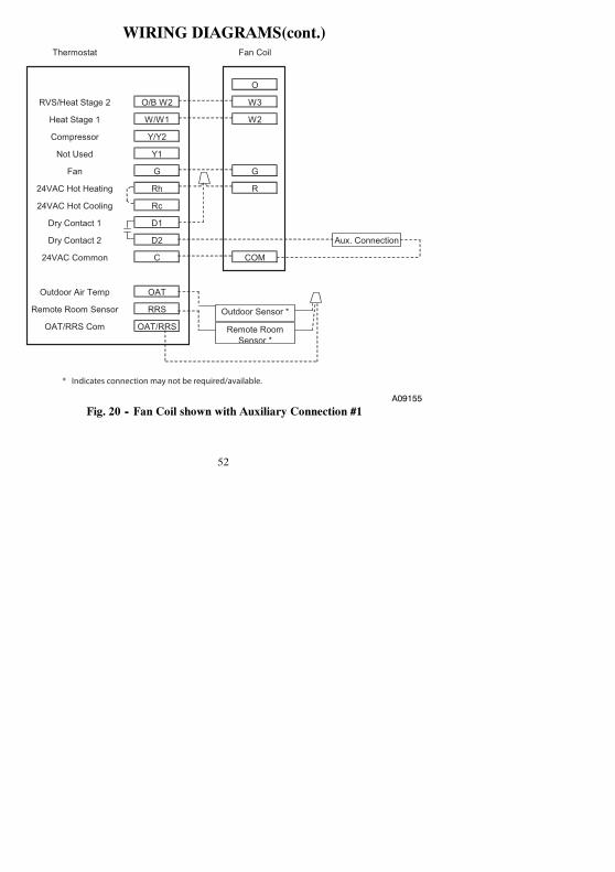
WIRING DIAGRAMS(cont.)Thermostat Fan Coil
O
RVS/Heat Stage 2 O/B W2 W3
Heat Stage 1 W/W1 W2
Compressor Y/Y2
Not Used Y1
Fan G G
24VAC Hot Heating Rh R
24VAC Hot Cooling Rc
Dry Contact 1 D1
Dry Contact 2 D2 Aux. Connection
24VAC Common C COM
Outdoor Air Temp OAT
Remote Room Sensor RRS
OAT/RRS Com OAT/RRS
Outdoor Sensor *
Remote Room Sensor *
* Indicates connection may not be required/available.
A09155Fig. 20 -- Fan Coil shown with Auxiliary Connection #1

53
WIRING DIAGRAMS(cont.)Thermostat Fan Coil Air Conditioner
O
RVS/Heat Stage 2 O/B W2 W3
Heat Stage 1 W/W1 W2
Compressor Y/Y2 Y Y
Not Used Y1
Fan G G
24VAC Hot Heating Rh R R
24VAC Hot Cooling Rc
Dry Contact 1 D1
Dry Contact 2 D2
24VAC Common C COM COM
Outdoor Air Temp OAT
Remote Room Sensor RRS
OAT/RRS Com OAT/RRS
Outdoor Sensor *
Remote Room Sensor *
* Indicates connection may not be required/available.
A09175
Fig. 21 -- Fan Coil with Air Conditioner

54
WIRING DIAGRAMS(cont.)Thermostat Fan Coil
O
RVS/Heat Stage 2 O/B W2 W3
Heat Stage 1 W/W1 W2
Compressor Y/Y2
Not Used Y1
Fan G G
24VAC Hot Heating Rh R
24VAC Hot Cooling Rc
Dry Contact 1 D1
Dry Contact 2 D2 Aux. Connection
24VAC Common C COM
Outdoor Air Temp OAT
Remote Room Sensor RRS
OAT/RRS Com OAT/RRS
Outdoor Sensor *
Remote Room Sensor *
* Indicates connection may not be required/available.
A09156
Fig. 22 -- Fan Coil shown with Auxiliary Connection #2(Heat pump/air conditioner removed for clarity)

55
WIRING DIAGRAMS(cont.)Thermostat Furnace Air Conditioner
Heat Stage 1 W/W1 W/W1
Compressor Y/Y2 Y/Y2 Y
Not Used Y1
Fan G G
24VAC Hot Heating Rh R R
24VAC Hot Cooling Rc
Dry Contact 1 D1
Dry Contact 2 D2
24VAC Common C COM COM
Outdoor Air Temp OAT
Remote Room Sensor RRS
OAT/RRS Com OAT/RRS
Outdoor Sensor *
Remote Room Sensor *
* Heat Stage 2 O/B W2 W2*
* Indicates connection may not be required/available.
A09157
Fig. 23 -- Furnace with Air Conditioner

56
WIRING DIAGRAMS(cont.)Thermostat
RVS/Heat Stage 2 O/B W2
Heat Stage 1 W/W1
Compressor Y/Y2
Not Used Y1
Fan G G
24VAC Hot Heating Rh R
24VAC Hot Cooling Rc
Dry Contact 1 D1
Dry Contact 2 D2
24VAC Common C C
Outdoor Air Temp OAT
Remote Room Sensor RRS
OAT/RRS Com OAT/RRS
A09158
Fig. 24 -- Thermostat with Dry Contact Control for Run Time

57
WIRING DIAGRAMS(cont.)
Thermostat Furnace Air Conditioner
W2
RVS/Heat Stage 2 O/B W2
Heat Stage 1 W/W1 W/W1
Compressor Y/Y2 Y/Y2 Y
Not Used Y1
Fan G G
24VAC Hot Heating Rh R R
24VAC Hot Cooling Rc
Dry Contact 1 D1
Dry Contact 2 D2
24VAC Common C COM COM
Outdoor Air Temp OAT
Remote Room Sensor RRS
OAT/RRS Com OAT/RRS
Outdoor Sensor *
Remote Room Sensor *
* Indicates connection may not be required/available.
A09159
Fig. 25 -- 2--Stage Furnace with Air Conditioner(HP Thermostat Configured as AC)

58
WIRING DIAGRAMS(cont.)Single-Stage Single-Stage
Thermostat Furnace Air Conditioner
RVS/Heat Stage 2 O/B W2
Heat Stage 1 W/W1 W/W1
Compressor Low Y1
Compressor High Y/Y2 Y/Y2 Y
Fan G G
24VAC Hot Heating Rh R
24VAC Hot Cooling Rc R*
Dry Contact 1 D1
Dry Contact 2 D2
24VAC Common C COM COM
Outdoor Air Temp OAT
Remote Room Sensor RRS
OAT/RRS Com OAT/RRSOutdoor Sensor *
Remote Room Sensor *
* Indicates connection may not be required/available.NOTE: Rc/Rh jumper is cut on the Equipment Control Module.
A09160
Fig. 26 -- Single--stage Furnace with Air Conditioner and Split Power

59
THERMOSTAT CONFIGURATION RECORDInstaller_________________________
Model Number_____________________________
Date_______________________
A. Hardware Configuration__________ Seal Hole In Wall
B. Mode Settings__________ Mode (Off, Heat, Cool, Auto, Em Heat)
__________ Heating Setpoint Value
__________ Cooling Setpoint Value
__________ Fan (Auto or On)
C. Home, Away, Sleep SettingsHeat Cool
Home ____ ____
Away ____ ____
Sleep ____ ____D. Schedule (For Programmable Thermostats)
Period 1 Period 2 Period 3 Period 4
Time Heat Cool Time Heat Cool Time Heat Cool Time Heat Cool
AllDays ____ ____ ____ ____ ____ ____ ____ ____ ____ ____ ____ ____Week-days ____ ____ ____ ____ ____ ____ ____ ____ ____ ____ ____ ____Week-end ____ ____ ____ ____ ____ ____ ____ ____ ____ ____ ____ ____

60
E Configuration Options
Option 01 ____ Equipment Type
Option 02 ____ Clean Filter Timer Adjustment
Option 03* ____ Fahrenheit/Centigrade Selection
Option 04 ____ Fan (G) on with W/W1 Selection
Option 05 ____ Room Air Temperature Sensing
Option 06 ____ Cooling Lockout Below 55_F Selection (only available if outdoor air sensor is present)
Option 07 ____ Zoning
Option 08 ____ Auxiliary Heat Lockout Temperature Setting (only available when heat pump is used and whenoutdoor air temperature sensor is present)
Option 10 ____ Reversing Valve
Option 11 ____ Adjustable Setpoint Deadband
Option 12 ____ Smart Recovery (programmable models only)
Option 13 ____ Room Air Temperature Offset Adjustment
Option 15 ____ Enable Auto Mode
Option 16 ____ Cycles Per Hour
Option 17 ____ Time Between Stages
Option 18* ____ Backlight Configuration
Option 19 ____ Dry Contact (programmable models only)
Option 20 ____ Outdoor Air Temperature Offset Adjustment

61
E Configuration Options (cont)
Option 21* ____ Keypad Lockout
Option 24* ____ Programmable/Non--Programmable (programmable models only)
Option 25* ____ Number of Programmable Periods Per Day (programmable models only)
Option 26 ____ Minimum Cooling Setpoint
Option 27 ____ Maximum Heating Setpoint
Option 28 ____ UV Light Reminder
Option 29 ____ Humidifier Pad Reminder
Option 30* ____ Programmable Fan (programmable models only)
Option 31* ____ Daylight Savings Time Configuration (programmable models only)
Option 32 ____ Furnace Heat Staging
Option 33 ____ Single or Two--Piece Installation
Option 41 ____ Variable Speed Blower
Option 44 ____ Super Comfort Heat
* Options with an asterisk can also be set/changed by the homeowner.

62
NOTES

63
NOTES

64
NOTES


997---060390---7---RCopyright 2013 Bryant Corporation 7310 W Morris St. Indianapolis, IN 46231
IIT6---PAC---07 Replaces: IIT6---PAC---06
Edition Date: 07/13
Manufacturer reserves the right to change, at any time, specifications and designs without notice
and without obligations.
![System Installation Guide - Honeywell · Prestige™ Installation Guide 6 System-specific wiring guides Heat pump systems 2H/2C Heat Pump[10] C 24VAC common R Power [1] Rc [R+Rc joined](https://static.fdocuments.net/doc/165x107/5e231155c6c550062235401b/system-installation-guide-honeywell-prestigea-installation-guide-6-system-specific.jpg)