INSTALLATION INSTRUCTION W Track Recessed 120V Flange - s3.amazonaws.com · WT4-RT, WT8-RT, WT12-RT...
8
WAC Lighting www.waclighting.com Phone (800) 526.2588 • Fax (800) 526.2585 Headquarters/Eastern Distribution Center 44 Harbor Park Drive • Port Washington, NY 11050 Phone (516) 515.5000 • Fax (516) 515.5050 Western Distribution Center 1750 Archibald Ave • Ontario, CA 91761 Phone (800) 526.2588 • Fax (800) 526.2585 WAC Lighting retains the right to modify the design of our products at any time as part of the company's continuous improvement program. JULY, 2014 INSTALLATION INSTRUCTION W Track Recessed 120V Flange WT4-RT, WT8-RT, WT12-RT SAFETY INSTRUCTION • Read all of these instructions before installing the track system. • Turn off power at main switch before installing or modifying the system. • Do not install within six inches of any curtain or combustible materials. • Do not install less than 5 feet above a floor. • Do not install in damp or wet locations. • Do not install concealed, or extended through building walls. • Do not attempt to energize anything other than a track light fixture. • This track system shall only be supplied with two single 120V, 60Hz, 20amp branch circuits. • Do not load to more than 20 amps per circuit. Although track light systems may seem to operate acceptably, a dangerous overload of the neutral may occur and result in a risk of fire. • Check with a qualified electrician before wiring. • All of the installations shall be in accordance with NEC and all local codes. • Save these installation instructions and refer to them when additions or changes to the track configuration are made. MOUNTING OPTIONS Generally, for any mounting method, do not exceed 4 feet between mounting points, and do not exceed 6 inches (for 4 feet of track or less in length) or 12 inches (for track that is greater than 4 feet) from each end of the single track section. Always use two or more mounting supports for each track length. A: STRAP MOUNTING • Remove the End Cap and save. • Slide the perforated hanger straps (not included, can be purchased in a hardware store) into the groove in the side of the track. An equal number of straps should be mounted on each side of the track. • Wrap the straps around the building structure or nail the straps to the structure. They should be positioned evenly to balance the track. • Placing one hanger strap every foot, per side is recommended. • Push End Cap into the track at the end of the track and secure by screw. • The hanger strap can be bought at a hardware store, recommend size is 11/16 inch (17mm) in width. B: DIRECT MOUNTING • Mounting slots in top of track can be knocked out and are spaced every 10 inches for convenience. • Mount as shown using a mounting screw every 2 feet is recommended. • Additional supports may be added for heavier load applications.
Transcript of INSTALLATION INSTRUCTION W Track Recessed 120V Flange - s3.amazonaws.com · WT4-RT, WT8-RT, WT12-RT...

WAC Lightingwww.waclighting.comPhone (800) 526.2588 • Fax (800) 526.2585
Headquarters/Eastern Distribution Center44 Harbor Park Drive • Port Washington, NY 11050Phone (516) 515.5000 • Fax (516) 515.5050
Western Distribution Center 1750 Archibald Ave • Ontario, CA 91761Phone (800) 526.2588 • Fax (800) 526.2585
WAC Lighting retains the right to modify the design of our products at any time as part of the company's continuous improvement program. JuLy, 2014
INSTALLATION INSTRUCTIONW Track Recessed 120V FlangeWT4-RT, WT8-RT, WT12-RT
SAFETY INSTRUCTION• Read all of these instructions before installing the track system.• Turn off power at main switch before installing or modifying the system.• Do not install within six inches of any curtain or combustible materials.• Do not install less than 5 feet above a floor.• Do not install in damp or wet locations.• Do not install concealed, or extended through building walls.• Do not attempt to energize anything other than a track light fixture.• This track system shall only be supplied with two single 120V, 60Hz, 20amp branch circuits. • Do not load to more than 20 amps per circuit. Although track light systems may seem to operate acceptably, a dangerous
overload of the neutral may occur and result in a risk of fire.• Check with a qualified electrician before wiring.• All of the installations shall be in accordance with NEC and all local codes.• Save these installation instructions and refer to them when additions or changes to the track configuration are made.
MOUNTING OPTIONSGenerally, for any mounting method, do not exceed 4 feet between mounting points, and do not exceed 6 inches (for 4 feet of track or less in length) or 12 inches (for track that is greater than 4 feet) from each end of the single track section. Always use two or more mounting supports for each track length.
A: STRAP MOUNTING
• Remove the End Cap and save.• Slide the perforated hanger straps (not included, can be
purchased in a hardware store) into the groove in the side of the track. An equal number of straps should be mounted on each side of the track.
• Wrap the straps around the building structure or nail the straps to the structure. They should be positioned evenly to balance the track.
• Placing one hanger strap every foot, per side is recommended.• Push End Cap into the track at the end of the track and secure
by screw.• The hanger strap can be bought at a hardware store,
recommend size is 11/16 inch (17mm) in width.
B: DIRECT MOUNTING
• Mounting slots in top of track can be knocked out and are spaced every 10 inches for convenience.
• Mount as shown using a mounting screw every 2 feet is recommended.
• Additional supports may be added for heavier load applications.

WAC Lightingwww.waclighting.comPhone (800) 526.2588 • Fax (800) 526.2585
Headquarters/Eastern Distribution Center44 Harbor Park Drive • Port Washington, NY 11050Phone (516) 515.5000 • Fax (516) 515.5050
Western Distribution Center 1750 Archibald Ave • Ontario, CA 91761Phone (800) 526.2588 • Fax (800) 526.2585
WAC Lighting retains the right to modify the design of our products at any time as part of the company's continuous improvement program. JuLy, 2014
C: SUSPENSION MOUNTING
• Slide or snap the hanger clips (WMT-RT) onto the track, and space the clips evenly along the track length.
• Secure the bolt and make sure the hanger clips tightly hook in the track groove.
• Assemble the stem or cable suspender (refer to WT/WHT track suspension system) to the hanger clips. Level track and secure to building structure.
• Recommended: two clips for 4’ track, three clips for 8’ track, and four clips for 12’ track. Always use more than one clip for each track length. Additional clips may be added for more support.
FEED OPTIONS
LIVE END CONNECTOR CAN BE FED DIRECTLY FROM ABOVE USING A 1/2 INCH OR 3/4 INCH ELECTRICAL CONNECTOR.
• Make sure power is off before wiring.• Note the polarity indicator of the track and accessories• Remove cover and save.• Remove knockout in top plate.• Secure conduit by conduit connector (1/2 or 3/4 size
recommended) to top plate and lock the nut.• Pass wires (12AWG) through conduit and connector.
Cut and strip each end of the wire, then a single conductor is clamped directly under the head of the screw when it is tight-ened. The single conductor is bent around the screw in a 3/4 loop, insert the wires to the corresponding terminals (see fig. below) and secure tightly with a screw.
• Secure the track to the ceiling (see mounting options on previous page).
• Replace the cover.• Insert the spline and secure to the track with two screws.
INSTALLATION INSTRUCTIONW Track Recessed 120V FlangeWT4-RT, WT8-RT, WT12-RT
WAC Lightingwww.waclighting.comPhone (800) 526.2588 • Fax (800) 526.2585
Headquarters/Eastern Distribution Center44 Harbor Park Drive • Port Washington, NY 11050Phone (516) 515.5000 • Fax (516) 515.5050
Western Distribution Center 1750 Archibald Ave • Ontario, CA 91761Phone (800) 526.2588 • Fax (800) 526.2585
WAC Lighting retains the right to modify the design of our products at any time as part of the company's continuous improvement program. JuLy, 2014
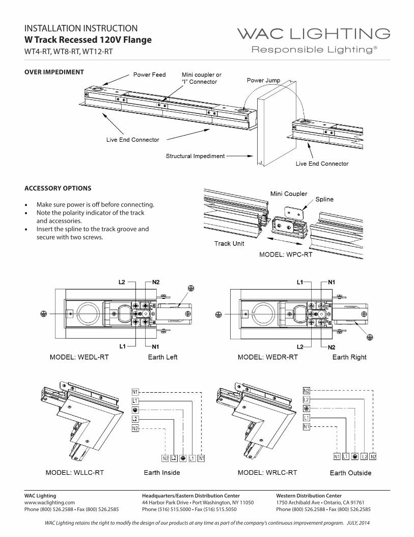
OVER IMPEDIMENT
INSTALLATION INSTRUCTIONW Track Recessed 120V FlangeWT4-RT, WT8-RT, WT12-RT
ACCESSORY OPTIONS
• Make sure power is off before connecting.• Note the polarity indicator of the track
and accessories.• Insert the spline to the track groove and
secure with two screws.

WAC Lightingwww.waclighting.comPhone (800) 526.2588 • Fax (800) 526.2585
Headquarters/Eastern Distribution Center44 Harbor Park Drive • Port Washington, NY 11050Phone (516) 515.5000 • Fax (516) 515.5050
Western Distribution Center 1750 Archibald Ave • Ontario, CA 91761Phone (800) 526.2588 • Fax (800) 526.2585
WAC Lighting retains the right to modify the design of our products at any time as part of the company's continuous improvement program. JuLy, 2014
INSTALLATION INSTRUCTIONW Track Recessed 120V Flange WT4-RT, WT8-RT, WT12-RT
FIELD CUTTING AND FIELD DRILLING
• Remove the end cap and save.• Use a metal cutting power saw (preferably in a miter
box) to cut the track, insulation material, and copper bus bars vertically with one straight cut.
• If the mounting openings are not in the proper position to secure after field cutting, use a power drill to drill an appropriate number of mounting holes. The holes should be 3/16” in diameter, and drill in the top centerline of the track along the track length.
• CAUTION: Remove any burrs that may have resulted from the cut or drill. There should be no burrs between the copper wires and the aluminum track housing.
• Replace the End Cap at the end of track and secure with a screw.

WAC Lightingwww.waclighting.comPhone (800) 526.2588 • Fax (800) 526.2585
Headquarters/Eastern Distribution Center44 Harbor Park Drive • Port Washington, NY 11050Phone (516) 515.5000 • Fax (516) 515.5050
Western Distribution Center 1750 Archibald Ave • Ontario, CA 91761Phone (800) 526.2588 • Fax (800) 526.2585
WAC Lighting retains the right to modify the design of our products at any time as part of the company's continuous improvement program. JuLy, 2014
INSTALLATION INSTRUCTIONW Track Recessed 277V FlangeWHT4-RT, WHT8-RT, WHT12-RT
SAFETY INSTRUCTION• Read all of these instructions before installing the track system.• Turn off power at main switch before installing or modifying the system.• Do not install within six inches of any curtain or combustible materials.• Do not install less than 5 feet above a floor.• Do not install in damp or wet locations.• Do not install concealed, or extended through building walls.• Do not attempt to energize anything other than a track light fixture.• This track system shall only be supplied with two single 120V, 60Hz, 20amp branch circuits. • Do not load to more than 20 amps per circuit. Although track light systems may seem to operate acceptably,
a dangerous overload of the neutral may occur and result in a risk of fire.• Check with a qualified electrician before wiring.• All of the installations shall be in accordance with NEC and all local codes.• Save these installation instructions and refer to them when additions or changes to the track configuration are made.
MOUNTING OPTIONSGenerally, for any mounting method, do not exceed 4 feet between mounting points, and do not exceed 6 inches (for 4 feet of track or less in length) or 12 inches (for track that is greater than 4 feet) from each end of the single track section. Always use two or more mounting supports for each track length.
A: STRAP MOUNTING
• Remove the End Cap and save.• Slide the perforated hanger straps (not included, can be
purchased in a hardware store) into the groove in the side of the track. An equal number of straps should be mounted on each side of the track.
• Wrap the straps around the building structure or nail the straps to the structure. They should be positioned evenly to balance the track.
• Placing one hanger strap every foot per side is recommended.• Push End Cap into the track at the end of the track
and secure by screw.• The hanger strap can be bought at a hardware store,
recommend size is 11/16 inch (17mm) in width.• Use clips or plates (by others) to be accommodated mounting
on the 1/2 inch of the ceiling board.
B: DIRECT MOUNTING
• Mounting slots in top of track can be knocked out and are spaced every 10 inches for convenience.
• Mount as shown using a mounting screw every 2 feet is recommended.
• Additional supports may be added for heavier load applications.

WAC Lightingwww.waclighting.comPhone (800) 526.2588 • Fax (800) 526.2585
Headquarters/Eastern Distribution Center44 Harbor Park Drive • Port Washington, NY 11050Phone (516) 515.5000 • Fax (516) 515.5050
Western Distribution Center 1750 Archibald Ave • Ontario, CA 91761Phone (800) 526.2588 • Fax (800) 526.2585
WAC Lighting retains the right to modify the design of our products at any time as part of the company's continuous improvement program. JuLy, 2014
INSTALLATION INSTRUCTIONW Track Recessed 277V FlangeWHT4-RT, WHT8-RT, WHT12-RT
C: SUSPENSION MOUNTING
• Slide or snap the hanger clips (WMT-RT) onto the track, and space the clips evenly along the track length.
• Secure the bolt and make sure the hanger clips tightly hook in the track groove.
• Assemble the stem or cable suspender (refer to WT/WHT track suspension system) to the hanger clips. Level track and secure to building structure.
• Recommended: two clips for 4’ track, three clips for 8’ track, and four clips for 12’ track. Always use more than one clip for each track length. Additional clips may be added for more support.
Feed options
Live End Connector can be fed directly from above using a 1/2 inch or 3/4 inch electrical connector.• Make sure power is off before wiring.• Note the polarity indicator of the track and accessories.• Remove cover and save.• Remove knockout in top plate.• Secure conduit by conduit connector (1/2 or 3/4 size
recommended) to top plate and lock the nut.• Pass wires (12AWG) through conduit and connector.
Cut and strip each end of the wire, then a single conductor is clamped directly under the head of the screw when it is tightened. The single conductor is bent around the screw in a 3/4 loop, insert the wires to the corresponding terminals (see fig. below) and secure tightly with a screw.
• Secure the track to the ceiling (see mounting options on previous page).
• Replace the cover.• Insert the spline and secure to the track with two screws.

WAC Lightingwww.waclighting.comPhone (800) 526.2588 • Fax (800) 526.2585
Headquarters/Eastern Distribution Center44 Harbor Park Drive • Port Washington, NY 11050Phone (516) 515.5000 • Fax (516) 515.5050
Western Distribution Center 1750 Archibald Ave • Ontario, CA 91761Phone (800) 526.2588 • Fax (800) 526.2585
WAC Lighting retains the right to modify the design of our products at any time as part of the company's continuous improvement program. JuLy, 2014
INSTALLATION INSTRUCTIONW Track Recessed 277V FlangeWHT4-RT, WHT8-RT, WHT12-RT
OVER IMPEDIMENT
ACCESSORY OPTIONS
• Make sure power is off before connecting.• Note the polarity indicator of the track
and accessories.• Insert the spline to the track groove and
secure with two screws.

WAC Lightingwww.waclighting.comPhone (800) 526.2588 • Fax (800) 526.2585
Headquarters/Eastern Distribution Center44 Harbor Park Drive • Port Washington, NY 11050Phone (516) 515.5000 • Fax (516) 515.5050
Western Distribution Center 1750 Archibald Ave • Ontario, CA 91761Phone (800) 526.2588 • Fax (800) 526.2585
WAC Lighting retains the right to modify the design of our products at any time as part of the company's continuous improvement program. JuLy, 2014
INSTALLATION INSTRUCTIONW Track Recessed 277V FlangeWHT4-RT, WHT8-RT, WHT12-RT