Installation Guidessbu-t.psn-web.net/.../PGQX2169YAC1_WJ-NX200KG_IG_en.pdfActivation Key Card ........
36
Before attempting to connect or operate this product, please read these instructions carefully and save this manual for future use. The model number is abbreviated in some descriptions in this manual. Installation Guide Network Disk Recorder Model No. WJ-NX200K/G Network Disk Recorder WJ-NX200
-
Upload
nguyenlien -
Category
Documents
-
view
220 -
download
0
Transcript of Installation Guidessbu-t.psn-web.net/.../PGQX2169YAC1_WJ-NX200KG_IG_en.pdfActivation Key Card ........

Before attempting to connect or operate this product,please read these instructions carefully and save this manual for future use.
The model number is abbreviated in some descriptions in this manual.
Installation GuideNetwork Disk Recorder Model No. WJ-NX200K/G
Network Disk Recorder WJ-NX200
2
ContentsIntroduction .............................................................................................................................. 4
Standard accessories ...............................................................................................................................................................4About the user manuals ............................................................................................................................................................4About Additional Camera Kit (option) .......................................................................................................................................5About Secure Communication Kit (option)................................................................................................................................5About the business intelligence function (option) .....................................................................................................................5Precautions for installation ........................................................................................................................................................5Basic operations .......................................................................................................................................................................7Setup menu ...............................................................................................................................................................................9
Operations flow ..................................................................................................................... 101 Obtain the license (Registration Key) ............................................................................. 122 Installation of the hard disk drive .................................................................................... 13
Install the hard disk drives ......................................................................................................................................................13(When replacing the hard disk drives) .....................................................................................................................................14
3 Rack mounting .................................................................................................................. 15Installation procedure ..............................................................................................................................................................15
4 Connections ...................................................................................................................... 16Connection of cameras and a mouse .....................................................................................................................................16Connection of monitors ..........................................................................................................................................................17Connection of a PC .................................................................................................................................................................18How to use the terminals of the ALARM/CONTROL ..............................................................................................................20Connection example for emergency recording .......................................................................................................................20Time and polarities of the ALARM/CONTROL connector .......................................................................................................24
5 Turn on the devices........................................................................................................... 25Turn on the power of the recorder ..........................................................................................................................................25(When turn off the power of the recorder) ...............................................................................................................................26
6 Register the license (Registration Key) .......................................................................... 277 Configure the minimum settings [Easy Start] ................................................................ 29Troubleshooting ..................................................................................................................... 32
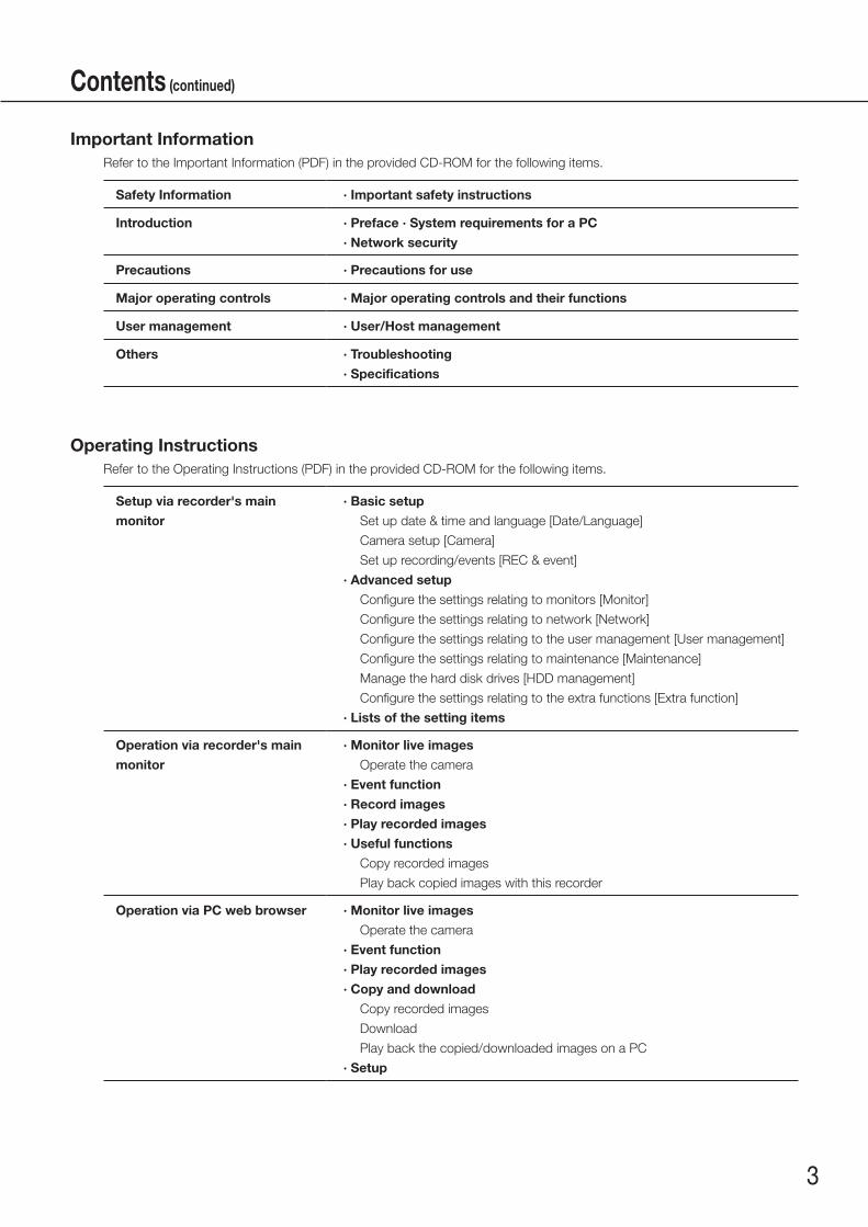
Important InformationRefer to the Important Information (PDF) in the provided CD-ROM for the following items.
Safety Information · Important safety instructions
Introduction · Preface · System requirements for a PC
· Network security
Precautions · Precautions for use
Major operating controls · Major operating controls and their functions
User management · User/Host management
Others · Troubleshooting
· Specifications
Operating InstructionsRefer to the Operating Instructions (PDF) in the provided CD-ROM for the following items.
Setup via recorder's main
monitor
· Basic setup
Set up date & time and language [Date/Language]
Camera setup [Camera]
Set up recording/events [REC & event]
· Advanced setup
Configure the settings relating to monitors [Monitor]
Configure the settings relating to network [Network]
Configure the settings relating to the user management [User management]
Configure the settings relating to maintenance [Maintenance]
Manage the hard disk drives [HDD management]
Configure the settings relating to the extra functions [Extra function]
· Lists of the setting items
Operation via recorder's main
monitor
· Monitor live images
Operate the camera
· Event function
· Record images
· Play recorded images
· Useful functions
Copy recorded images
Play back copied images with this recorder
Operation via PC web browser · Monitor live images
Operate the camera
· Event function
· Play recorded images
· Copy and download
Copy recorded images
Download
Play back the copied/downloaded images on a PC
· Setup
3
Contents (continued)
4
Introduction
About the user manuals
There are 4 manuals provided for the WJ-NX200K/G as follows.
Installation Guide (this book): Contains procedures how to install/connect this product, and descriptions of easy configurations.
Important Information (PDF): Contains preface, precautions, and major operating controls and their functions and specifications.
Operating Instructions (PDF): Contains descriptions of how to operate this product with a PC.Quick Reference Guide: Contains descriptions of how to configure the basic settings and how to use the
major functions.
Adobe® Reader® is required to read the PDF files (the setup instructions and the operating instructions) on the provided CD-ROM. When Adobe® Reader® is not installed on the PC, download the latest Adobe® Reader® from the Adobe web site and install it.
"NX200" shown in the instructions and illustrations used in these operating instructions indicate the WJ-NX200K/G.Refer to "readme.txt" on the provided CD-ROM for further information about the optional dedicated software, compatible network cameras (hereinafter, cameras) and their versions.Refer to the Panasonic support website (https://security.panasonic.com/support) for latest information about the compatible cameras and functions to be added or changed by firmware upgrade.The external appearance in the document may differ from the actual product within no influence range on operation due to improvement of the product.
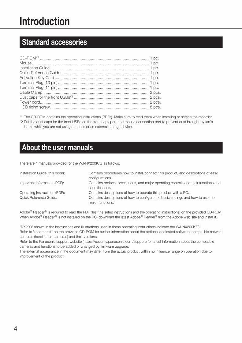
CD-ROM*1 .................................................................................................1 pc.Mouse ........................................................................................................1 pc.Installation Guide ........................................................................................1 pc.Quick Reference Guide ...............................................................................1 pc.Activation Key Card ....................................................................................1 pc.Terminal Plug (10 pin) .................................................................................1 pc.Terminal Plug (11 pin) .................................................................................1 pc.Cable Clamp ..............................................................................................2 pcs.Dust caps for the front USBs*2 ...................................................................2 pcs.Power cord .................................................................................................2 pcs.HDD fixing screw ........................................................................................8 pcs.
*1 The CD-ROM contains the operating instructions (PDFs). Make sure to read them when installing or setting the recorder.*2 Put the dust caps for the front USBs on the front copy port and mouse connection port to prevent dust brought by fan's
intake while you are not using a mouse or an external storage device.
Standard accessories

5
Introduction (continued)
Number of cameras to be used in the system (9 cameras in basic system) can be increased to 16, 24 and 32 (maximum) by purchasing the Additional Camera Kit (WJ-NXE20, WJ-NXE20W: option). Refer to following table regarding camera numbers.
Additional Camera KitWJ-NXE20, WJ-NXE20W
NX200 only(No additional license)
one Additional Camera Kit(one additional license)
two Additional Camera Kit(two additional licenses)
three Additional Camera Kit(three additional licenses)
up to 9 cameras up to 16 cameras up to 24 cameras up to 32 cameras
Registering the license of the additional business intelligence kit WJ-NXF02, WJ-NXF02W (option) allows the recorder to detect faces whose features are similar to the registered faces by comparing face images in live image with the registered face images (face matching function). The statistical processing for the results of the face matching will also become available and it displays the result on the main monitor connected with the recorder.
About Additional Camera Kit (option)
About the business intelligence function (option)
This product is designed to be used indoors.
Panasonic assumes no responsibility for injuries or property damage resulting from failures arising out of improper installation or operation inconsistent with this documentation.
Do not place this product in the following places:• Locations exposed to direct sunlight• Locations subject to having strong vibration or impact• Locations near magnetic field sources such as a televi-
sion or speakers• Locations near the devices that emit large sound and
generate vibration by sound pressure• Locations where condensation forms easily, where tem-
perature changes greatly or where humidity level is high
• Locations subject to steam and oil smoke such as a kitchen
• Locations which are not level• Locations subject to dust• Locations where it may get wet from rain or water splash
Do not install this product in locations where the product or the cables can be destroyed or damaged by persons with malicious intent.
Precautions for installation
Registering a license of a secure communication kit (option) to the recorder enables secure communication* with cameras. Each secure communication kit differs in the number of cameras that can be registered as shown in the table below. Use several licenses as necessary.* Encrypted communication using an electronic certificate
WJ-NXS01, WJ-NXS01W WJ-NXS04, WJ-NXS04W WJ-NXS16, WJ-NXS16W WJ-NXS32, WJ-NXS32W
1 camera 4 cameras 16 cameras 32 cameras
About Secure Communication Kit (option)
6
Introduction (continued)
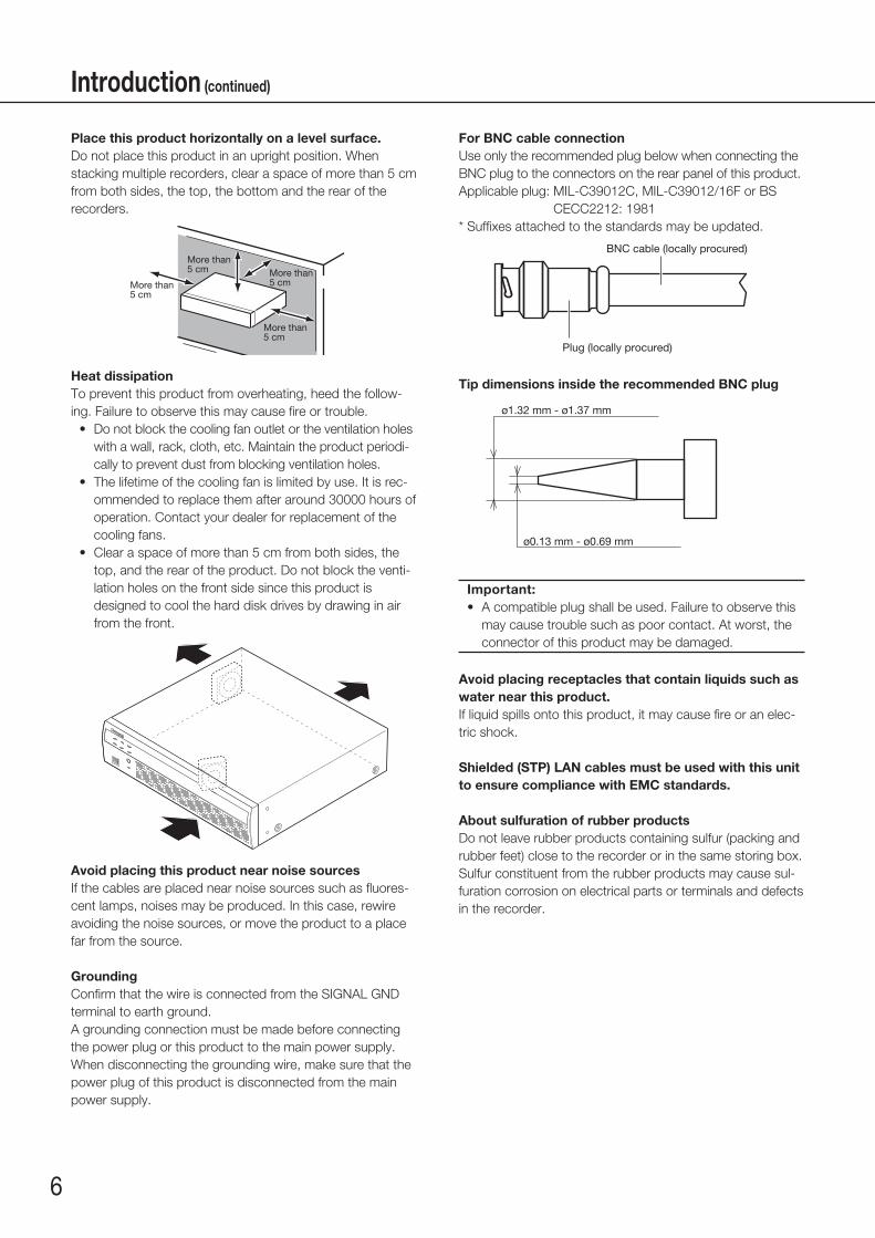
Place this product horizontally on a level surface.Do not place this product in an upright position. When stacking multiple recorders, clear a space of more than 5 cm from both sides, the top, the bottom and the rear of the recorders.
More than 5 cm More than
5 cm
More than 5 cm
More than 5 cm
Heat dissipationTo prevent this product from overheating, heed the follow-ing. Failure to observe this may cause fire or trouble.
• Do not block the cooling fan outlet or the ventilation holes with a wall, rack, cloth, etc. Maintain the product periodi-cally to prevent dust from blocking ventilation holes.
• The lifetime of the cooling fan is limited by use. It is rec-ommended to replace them after around 30000 hours of operation. Contact your dealer for replacement of the cooling fans.
• Clear a space of more than 5 cm from both sides, the top, and the rear of the product. Do not block the venti-lation holes on the front side since this product is designed to cool the hard disk drives by drawing in air from the front.
Avoid placing this product near noise sourcesIf the cables are placed near noise sources such as fluores-cent lamps, noises may be produced. In this case, rewire avoiding the noise sources, or move the product to a place far from the source.
GroundingConfirm that the wire is connected from the SIGNAL GND terminal to earth ground.A grounding connection must be made before connecting the power plug or this product to the main power supply. When disconnecting the grounding wire, make sure that the power plug of this product is disconnected from the main power supply.
For BNC cable connectionUse only the recommended plug below when connecting the BNC plug to the connectors on the rear panel of this product.Applicable plug: MIL-C39012C, MIL-C39012/16F or BS
CECC2212: 1981* Suffixes attached to the standards may be updated.
BNC cable (locally procured)
Plug (locally procured)
Tip dimensions inside the recommended BNC plug
ø1.32 mm - ø1.37 mm
ø0.13 mm - ø0.69 mm
Important:• A compatible plug shall be used. Failure to observe this
may cause trouble such as poor contact. At worst, the connector of this product may be damaged.
Avoid placing receptacles that contain liquids such as water near this product.If liquid spills onto this product, it may cause fire or an elec-tric shock.
Shielded (STP) LAN cables must be used with this unit to ensure compliance with EMC standards.
About sulfuration of rubber productsDo not leave rubber products containing sulfur (packing and rubber feet) close to the recorder or in the same storing box. Sulfur constituent from the rubber products may cause sul-furation corrosion on electrical parts or terminals and defects in the recorder.
7
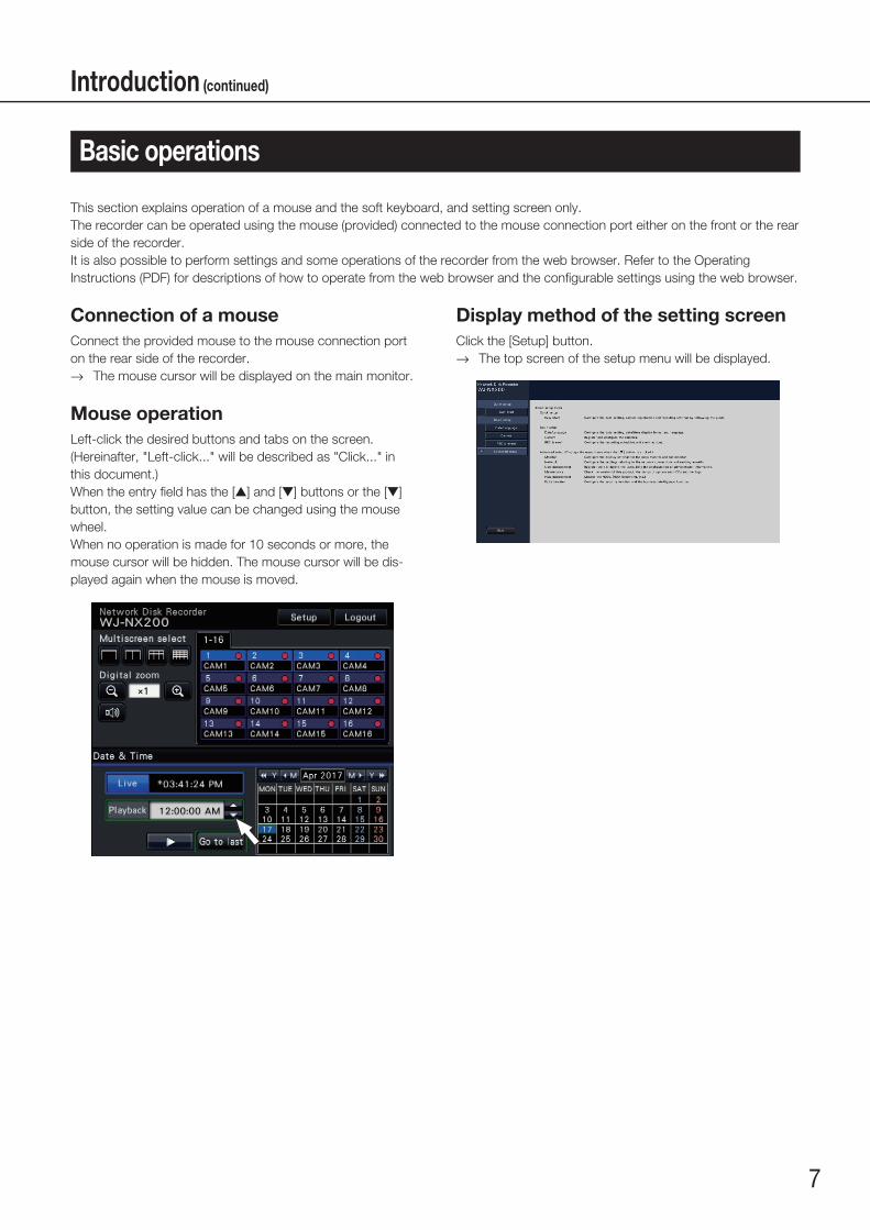
Display method of the setting screenClick the [Setup] button.
→→ The top screen of the setup menu will be displayed.
Connection of a mouseConnect the provided mouse to the mouse connection port on the rear side of the recorder.
→→ The mouse cursor will be displayed on the main monitor.
Mouse operationLeft-click the desired buttons and tabs on the screen.(Hereinafter, "Left-click..." will be described as "Click..." in this document.)When the entry field has the [▲] and [▼] buttons or the [▼] button, the setting value can be changed using the mouse wheel.When no operation is made for 10 seconds or more, the mouse cursor will be hidden. The mouse cursor will be dis-played again when the mouse is moved.
This section explains operation of a mouse and the soft keyboard, and setting screen only.The recorder can be operated using the mouse (provided) connected to the mouse connection port either on the front or the rear side of the recorder.It is also possible to perform settings and some operations of the recorder from the web browser. Refer to the Operating Instructions (PDF) for descriptions of how to operate from the web browser and the configurable settings using the web browser.
Basic operations
Introduction (continued)

8
About the operation of on-screen keyboardUse the on-screen keyboard to enter characters for the setting items. When clicking the [ ] icon beside the entry field, the on-screen keyboard will be displayed, and it will become possible to enter characters by clicking the character keys on the key-board.
On-screen keyboard screen
[Del all] buttonDeletes all the characters in the entry field.
[←]/[→] buttonMove the cursor in the entry field to either direction.
[Delete] buttonDeletes a character pointed by the cursor in the entry field.
[A/a] buttonThis button changes the characters to be entered between capital letters and small letters.
[Next] buttonChanges the keys to be displayed for character entry.The displayed keys are changed as follows: Keys for the language selected by the language selec-
tion pull-down menu → Combination characters → Special characters
[Enter] buttonDetermines the entered characters and closes the on-screen keyboard.
Note:• Basic operations are also applied to the "Login" window
and registration window for license.• Click the [×] button to close the window without deter-
mining the entered characters.
Entry field
Language selection pull-down menuClick the [▼] button to select the language for character entry.
Introduction (continued)

9
Configuration of each setting item in the setup menu should be completed in advance to use this recorder.The setup menu has the following levels for the setting items. On "Easy Start", the minimum settings required to operate the recorder will be performed, but other settings will remain default. On the [Basic setup] or [Advanced setup] page, the settings can be customized in accordance with a variety of operational modes.The following is the example of the setup menu that describes the features and operations.The setup menu will be displayed when clicking the [Setup] button (☞ page 7) at the upper right corner of the operational screen on the main monitor.The buttons of the setup pages will be displayed on the left column of the setup menu.
Setup menu
➀ [Home] button It is possible to return to the top screen (☞ page 7) of
the setup menu from any setup page.
➁ Setup menu panel Displays buttons of the setup pages.
➂ [Easy Start] button It is possible to configure the minimum settings required
to operate the recorder, such as date & time and cam-era registration.
➃ [Basic setup] – Setup page buttons Each "Basic setup" page will be displayed.
➄ [Advanced setup] button The buttons to open the corresponding setup pages of
the "Advanced setup" menu will be displayed. When clicking this button again, the buttons will be hidden.
➅ [Advanced setup] – Setup page buttons Each "Advanced setup" page will be displayed.
➆ Hierarchical display The name of the current setup page will be displayed in
the hierarchy. The tab name will also be included.
➇ Setup page Displays each setup page. If the current setup page is
composed of two or more tabs, it is possible to change the page display by clicking the tabs.
➈ [Exit] button Applies the settings to the recorder and closes the setup
menu to return to the operational screen (☞ page 11).
Except for some cases, the descriptions of this document follow the hierarchical display and setup pages.
Important:• If the settings are applied, all login users will be forcibly
logged out.
Introduction (continued)
➀
➁
➃
➂
➄
➅➇
➆
➈

10
1 Obtain the license (Registration Key)☞ Page 12 and Activation Key Card
2 Installation of the hard disk drive☞ Page 13
3 Rack mounting☞ Page 15
4 Connections☞ Page 16
5Turn on the devices
☞ Page 25
6Register the license (Registration Key)
☞ Page 27
Obtain the "Registration Key" of the recorder by following the instructions on the provided Activation Key Card. To increase the number of connected cameras, or to use the secure function or the business intelligence function, get the registration key of the additional license according to the appropriate Additional Kit (option). The obtained "Registration Key" will be used in Step 5.
Install the hard disk drives in the recorder.
Install the recorder in the rack. (☞ Page 15) Go to step 4 when not installing it in the rack.
Connect the camera and monitor to this product.
Turn on the power to launch in the following order.①Turn on the power of the camera and the monitor. ②Turn on the power of the recorder.
Register the Registration Key of the recorder. If necessary, register the "Registration Key" for each Additional kit.
Important:• Be sure to register the "Registration Key" of the recorder.
If the "Registration key" of the recorder is not registered, the Additional Kit cannot be registered.
After registration, click [Restart] button on the license registration screen to reboot the recorder and activate the license.
• The main monitor is required for the settings.* The settings can be done through a web browser on the PC (Refer to the Operating
Instructions (PDF)).• The PC is required for reading the Important Information, the Operating Instructions
(PDF) and camera settings.
Operations flow
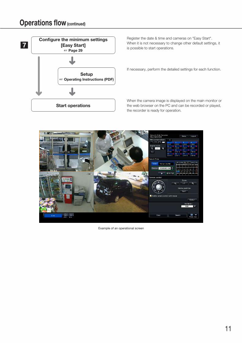
Example of an operational screen
11
7Configure the minimum settings
[Easy Start]☞ Page 29
Setup☞ Operating Instructions (PDF)
Start operations
Register the date & time and cameras on "Easy Start".When it is not necessary to change other default settings, it is possible to start operations.
If necessary, perform the detailed settings for each function.
When the camera image is displayed on the main monitor or the web browser on the PC and can be recorded or played, the recorder is ready for operation.
Operations flow (continued)

12
Keep the "Activation Key Card" provided with the recorder nearby.Obtain the "Registration Key" of the recorder by following the instructions on the provided Activation Key Card.To increase number of connected cameras, get the registration key number of the additional camera license according to the Additional Camera Kit (option).To use the secure function, get the registration key number of the additional secure license according to the Secure Communication Kit (option).To use the business intelligence function, get the registration key of the additional business intelligence license according to the additional business intelligence kit (option).* Each additional kit is the "Activation Key Card" with "the recorder ID number, activation ID number" for the applicable additional
license.
Note:• A PC or a mobile phone accessible to the Internet is necessary to acquire the registration key number.
1 Obtain the license (Registration Key)

13
2 Installation of the hard disk driveBefore installing the hard disk drives, turn off the power of the recorder first. When replacing the hard disk drives, the procedures will be same as those of installation. When installing or replacing the hard disk drives for playback use only (hard disk drives that are formerly used for recording), perform the link process.
Important:• When securing the hard disk drives to the HDD brackets, do not mistake the direction of the connectors. (Do not install the
hard disk drives in the opposite direction.)• When installing hard disk drives, use a low-torque powered screwdriver or a torque screwdriver to tighten screws with the
specified torque.• Hard disk drives are precise devices. Handle with care while keeping the following in mind.
• Do not subject the hard disk drive to any vibration or impact.• Before touching the hard disk drive, eliminate static electricity by touching a steel locker, etc. When holding the hard disk
drive, hold the both sides of the hard disk drive.• Do not touch the circuit board or the connectors to prevent the hard disk drive from damaging by static electricity.
• Contact your dealer for hard disk drives that works on the recorder. Please be forewarned that operation with any hard disk drive other than the specified models is not guaranteed under any circumstances.
• When using multiple hard disk drives, use the same model.• If different models are used together, even when the capacities of them are the same, the available capacity may be a few
percent smaller.
Note:• Hard disk drives are locally procured. Contact your dealer for purchasing, installing, and replacing the hard disk drives.
Install the hard disk drivesInstallation or replacement of the hard disk drives
Step 1Turn off the power of the recorder. (☞ Page 26)
Step 2Remove the HDD bracket screws (x2) on the HDD slots on the rear panel of the recorder, and pull out the HDD bracket.
HDD bracket screw
Step 3Install the hard disk drive into the HDD bracket using 4 HDD fixing screws (accessories).Tightening torque for the screws: 0.49 N·m
HDD fixing screw (accessory)
HDD fixing screw (accessory)
14
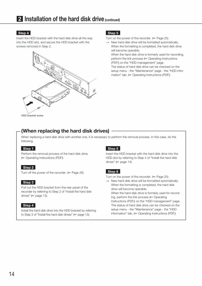
Step 4Insert the HDD bracket with the hard disk drive all the way into the HDD slot, and secure the HDD bracket with the screws removed in Step 2.
HDD bracket screw
Step 5Turn on the power of the recorder. (☞ Page 25)
→→ New hard disk drive will be formatted automatically. When the formatting is completed, the hard disk drive
will become operable. When the hard disk drive is formerly used for recording,
perform the link process (☞ Operating Instructions (PDF)) on the "HDD management" page.
The status of hard disk drive can be checked on the setup menu - the "Maintenance" page - the "HDD infor-mation" tab. (☞ Operating Instructions (PDF))
(When replacing the hard disk drives)When replacing a hard disk drive with another one, it is necessary to perform the removal process. In this case, do the following.
Step 1Perform the removal process of the hard disk drive. (☞ Operating Instructions (PDF))
Step 2Turn off the power of the recorder. (☞ Page 26)
Step 3Pull out the HDD bracket from the rear panel of the recorder by referring to Step 2 of "Install the hard disk drives" (☞ page 13).
Step 4Install the hard disk drive into the HDD bracket by referring to Step 3 of "Install the hard disk drives" (☞ page 13).
Step 5Insert the HDD bracket with the hard disk drive into the HDD slot by referring to Step 4 of "Install the hard disk drives" (☞ page 14).
Step 6Turn on the power of the recorder. (☞ Page 25)
→→ New hard disk drive will be formatted automatically. When the formatting is completed, the hard disk
drive will become operable. When the hard disk drive is formerly used for record-
ing, perform the link process (☞ Operating Instructions (PDF)) on the "HDD management" page.
The status of hard disk drive can be checked on the setup menu - the "Maintenance" page - the "HDD information" tab. (☞ Operating Instructions (PDF))
2 Installation of the hard disk drive (continued)
15
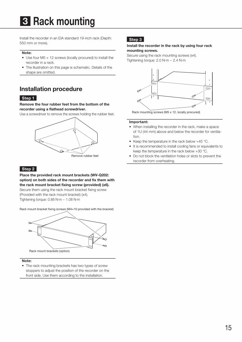
3 Rack mountingStep 3
Install the recorder in the rack by using four rack mounting screws.Secure using the rack mounting screws (x4).Tightening torque: 2.0 N·m ~ 2.4 N·m
Rack mounting screws (M5 x 12, locally procured)
Important:• When installing the recorder in the rack, make a space
of 1U (44 mm) above and below the recorder for ventila-tion.
• Keep the temperature in the rack below +45 °C.• It is recommended to install cooling fans or equivalents to
keep the temperature in the rack below +30 °C.• Do not block the ventilation holes or slots to prevent the
recorder from overheating.
Install the recorder in an EIA standard 19-inch rack (Depth: 550 mm or more).
Note:• Use four M5 × 12 screws (locally procured) to install the
recorder in a rack.• The illustration on this page is schematic. Details of the
shape are omitted.
Installation procedureStep 1
Remove the four rubber feet from the bottom of the recorder using a flathead screwdriver.Use a screwdriver to remove the screws holding the rubber feet.
Remove rubber feet
Step 2Place the provided rack mount brackets (WV-Q202: option) on both sides of the recorder and fix them with the rack mount bracket fixing screw (provided) (x6).Secure them using the rack mount bracket fixing screw (Provided with the rack mount bracket) (x4).Tightening torque: 0.88 N·m ~ 1.08 N·m
Rack mount bracket fixing screws (M4×10 provided with the bracket)
Rack mount brackets (option)
Note:• The rack mounting brackets has two types of screw
stoppers to adjust the position of the recorder on the front side. Use them according to the installation.

16
4 ConnectionsConnection of cameras and a mouseUp to 32 cameras can be connected to the Camera/PC port of the recorder via a PoE hub.Use a Ethernet cable (straight) to connect the recorder and the PoE hub.Connect the provided mouse to the mouse connection port on the front or rear side of the recorder.
Recorder
Ethernet cable (locally procured): category 7 (straight) for WJ-NX200K/G
Mouse (provided)
PoE hub
Network camera (x 32 max.)(When 3 licenses are used for the additional camera kit)
Note:• Make sure to use the wired network to connect with the recorder even for the cameras equipped with the wireless LAN func-
tion.

17
Connection of monitorsConnect a main monitor (to be used to display live images, recorded images or the setup menu) and a sub monitor (to be used to display live images only) to the HDMI (video/audio output) connectors using HDMI cables (optional). Connect a sub monitor (BNC) to the video output connector using a BNC cable (locally procured).
Recorder
BNC cable (locally procured)
Audio cable(option)
HDMI cable(option)
Powered speaker
Sub monitor (BNC)
Main monitor (HDMI)
HDMI cable (option)
* When outputting audio Connect a powered speaker.
Sub monitor (HDMI)
Note:• Use "High Speed HDMI® Cable". When the main monitor is used in 4K/25P(30P), use a 10.2 Gbps compatible HDMI cable.• To maintain the stable performance without deteriorating the image quality, use an HDMI cable whose length is 5 m or less.• Audio will be output from the monitor when the monitor is connected with an HDMI cable.• Same audio output from the main monitor will be heard from the speaker connected with an audio cable.• No audio will be heard from the sub monitor (HDMI) connected with an HDMI cable.
4 Connections (continued)
18
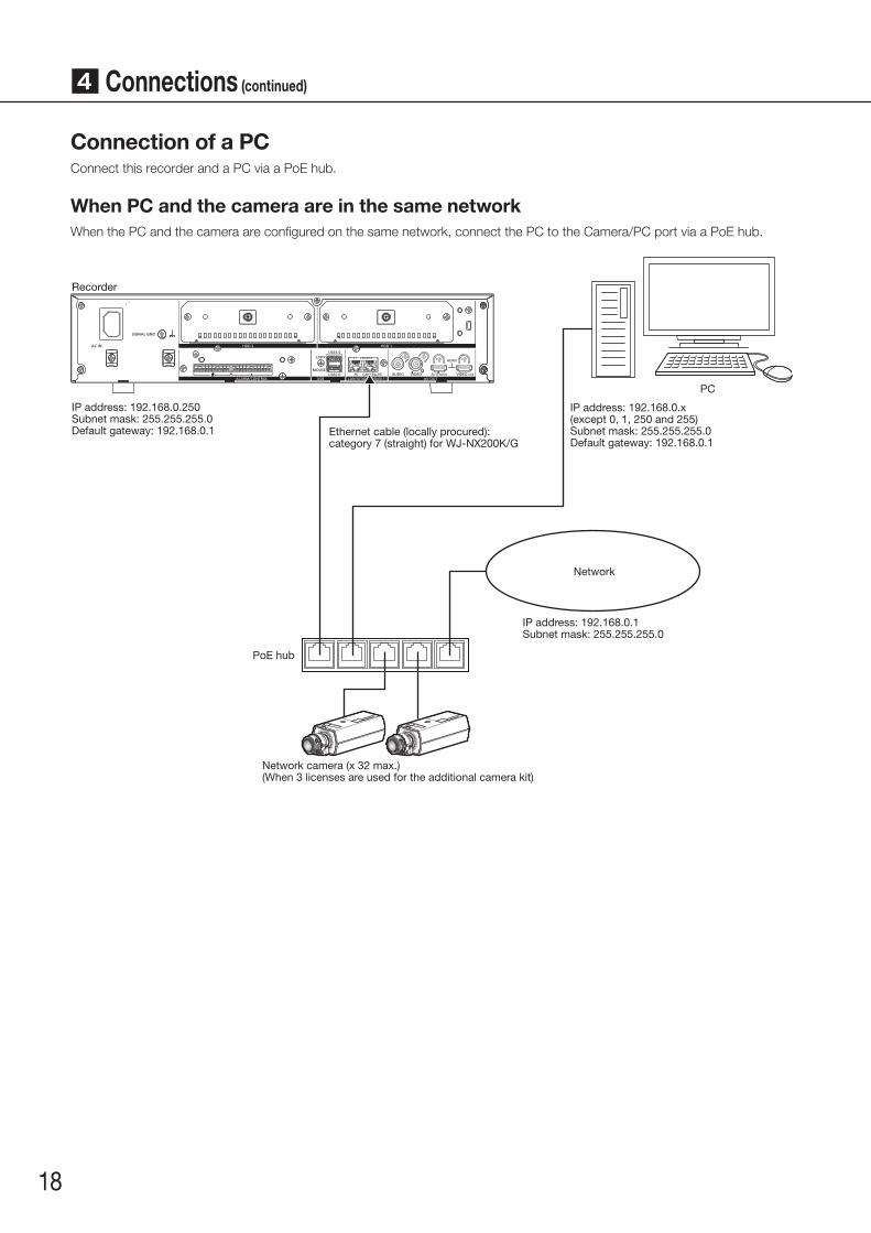
Connection of a PCConnect this recorder and a PC via a PoE hub.
When PC and the camera are in the same networkWhen the PC and the camera are configured on the same network, connect the PC to the Camera/PC port via a PoE hub.
Recorder
Network
PoE hub
Network camera (x 32 max.)(When 3 licenses are used for the additional camera kit)
PC
IP address: 192.168.0.250Subnet mask: 255.255.255.0Default gateway: 192.168.0.1 Ethernet cable (locally procured):
category 7 (straight) for WJ-NX200K/G
IP address: 192.168.0.1Subnet mask: 255.255.255.0
IP address: 192.168.0.x(except 0, 1, 250 and 255)Subnet mask: 255.255.255.0Default gateway: 192.168.0.1
4 Connections (continued)
19
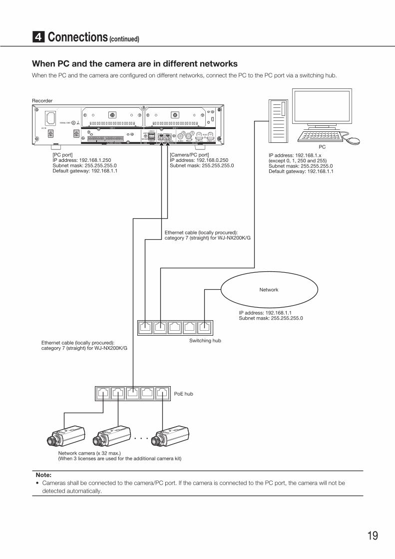
When PC and the camera are in different networksWhen the PC and the camera are configured on different networks, connect the PC to the PC port via a switching hub.
Recorder
Network
PoE hub
Switching hub
Network camera (x 32 max.)(When 3 licenses are used for the additional camera kit)
Ethernet cable (locally procured): category 7 (straight) for WJ-NX200K/G
Ethernet cable (locally procured): category 7 (straight) for WJ-NX200K/G
[Camera/PC port]IP address: 192.168.0.250Subnet mask: 255.255.255.0
[PC port]IP address: 192.168.1.250Subnet mask: 255.255.255.0Default gateway: 192.168.1.1
PC
IP address: 192.168.1.x(except 0, 1, 250 and 255)Subnet mask: 255.255.255.0Default gateway: 192.168.1.1
Note:• Cameras shall be connected to the camera/PC port. If the camera is connected to the PC port, the camera will not be
detected automatically.
4 Connections (continued)
IP address: 192.168.1.1Subnet mask: 255.255.255.0
20
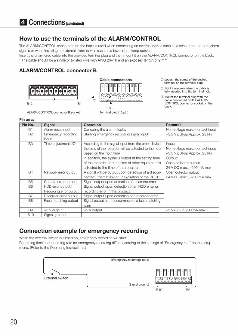
How to use the terminals of the ALARM/CONTROLThe ALARM/CONTROL connectors on the back is used when connecting an external device such as a sensor that outputs alarm signals or when installing an external alarm device such as a buzzer or a lamp outside.Insert the unarmored cable into the provided terminal plug and then mount it on the ALARM/CONTROL connector on the back.* The cable should be a single or twisted wire with AWG 26~16 and an exposed length of 9 mm.
ALARM/CONTROL connector B
B10 B1B
Cable connections
②①
① Loosen the screw of the desired terminal on the terminal plug.
② Tight the screw when the cable is fully inserted into the terminal hole.
③ Mount the terminal plug with the cable connected on the ALARM/CONTROL connector socket on the back.
③
Terminal plug (10 pin)ALARM/CONTROL connector B socket
Pin arrayPin No. Signal Operation Remarks
B1 Alarm reset input Canceling the alarm display Non-voltage make contact input+3.3 V pull-up Approx. 23 kΩB2 Emergency recording
inputStarting emergency recording signal input
B3 Time adjustment I/O According to the signal input from the other device, the time of the recorder will be adjusted to the hour based on the input timeIn addition, the signal is output at the setting time of the recorder and the time of other equipment is adjusted to the time of the recorder
Input:Non-voltage make contact input+3.3 V pull-up Approx. 23 kΩOutput:Open collector output24 V DC max., –200 mA max.
B4 Network error output A signal will be output upon detection of a discon-nected Ethernet link or IP expiration of the DHCP
Open collector output 24 V DC max., –200 mA max.
B5 Camera error output Signal output upon detection of a camera errorB6 HDD error output/
Recording error outputSignal output upon detection of an HDD error or recording error in this product
B7 Recorder error output Signal output upon detection of a recorder errorB8 Face matching output Signal output at the occurrence of a face matching
alarmB9 +5 V output +5 V output +5 V±0.5 V, 200 mA max.B10 Signal ground
Connection example for emergency recordingWhen the external switch is turned on, emergency recording will start.Recording time and recording rate for emergency recording differ according to the settings of "Emergency rec." on the setup menu. (Refer to the Operating Instructions.)
B2
(Emergency recording input)
(Signal ground)
External switch
B10
4 Connections (continued)
21
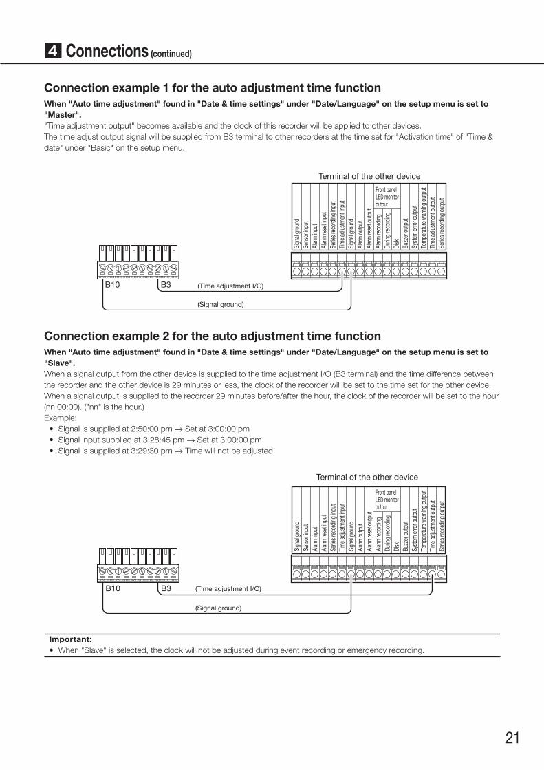
Connection example 1 for the auto adjustment time functionWhen "Auto time adjustment" found in "Date & time settings" under "Date/Language" on the setup menu is set to "Master"."Time adjustment output" becomes available and the clock of this recorder will be applied to other devices.The time adjust output signal will be supplied from B3 terminal to other recorders at the time set for "Activation time" of "Time & date" under "Basic" on the setup menu.
(Signal ground)
(Time adjustment I/O)B3B10
Terminal of the other device
Sign
al gr
ound
Sens
or in
put
Alar
m in
put
Alar
m re
set in
put
Serie
s rec
ordin
g inp
utTim
e adju
stmen
t inpu
tSi
gnal
grou
ndAl
arm
out
put
Alar
m re
set o
utpu
tAl
arm
reco
rding
Durin
g re
cord
ingDi
skBu
zzer
out
put
Syste
m er
ror o
utpu
tTe
mpe
ratu
re w
arnin
g ou
tput
Time a
djustm
ent o
utpu
tSe
ries r
ecor
ding
outp
ut
Front panelLED monitoroutput
Connection example 2 for the auto adjustment time functionWhen "Auto time adjustment" found in "Date & time settings" under "Date/Language" on the setup menu is set to "Slave".When a signal output from the other device is supplied to the time adjustment I/O (B3 terminal) and the time difference between the recorder and the other device is 29 minutes or less, the clock of the recorder will be set to the time set for the other device.When a signal output is supplied to the recorder 29 minutes before/after the hour, the clock of the recorder will be set to the hour (nn:00:00). ("nn" is the hour.)Example:
• Signal is supplied at 2:50:00 pm → Set at 3:00:00 pm• Signal input supplied at 3:28:45 pm → Set at 3:00:00 pm• Signal is supplied at 3:29:30 pm → Time will not be adjusted.
(Signal ground)
(Time adjustment I/O)B3B10
Terminal of the other device
Sign
al gr
ound
Sens
or in
put
Alar
m in
put
Alar
m re
set in
put
Serie
s rec
ordin
g inp
utTim
e adju
stmen
t inpu
tSi
gnal
grou
ndAl
arm
out
put
Alar
m re
set o
utpu
tAl
arm
reco
rding
Durin
g re
cord
ingDi
skBu
zzer
out
put
Syste
m er
ror o
utpu
tTe
mpe
ratu
re w
arnin
g ou
tput
Time a
djustm
ent o
utpu
tSe
ries r
ecor
ding
outp
ut
Front panelLED monitoroutput
Important:• When "Slave" is selected, the clock will not be adjusted during event recording or emergency recording.
4 Connections (continued)
22
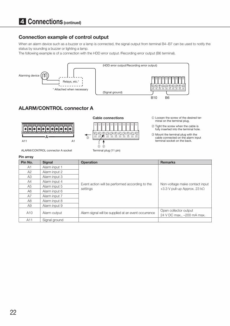
Connection example of control outputWhen an alarm device such as a buzzer or a lamp is connected, the signal output from terminal B4~B7 can be used to notify the status by sounding a buzzer or lighting a lamp.The following example is of a connection with the HDD error output /Recording error output (B6 terminal).
Alarming device
Relays, etc.*
* Attached when necessary
(HDD error output/Recording error output)
(Signal ground)
B10 B6
ALARM/CONTROL connector A
A11 A1
Cable connections ① Loosen the screw of the desired ter-minal on the terminal plug.
② Tight the screw when the cable is fully inserted into the terminal hole.
③ Mount the terminal plug with the cable connected on the alarm input terminal socket on the back.
③
Terminal plug (11 pin)ALARM/CONTROL connector A socket
A
②①
Pin array
Pin No. Signal Operation RemarksA1 Alarm input 1
Event action will be performed according to the settings
Non-voltage make contact input+3.3 V pull-up Approx. 23 kΩ
A2 Alarm input 2A3 Alarm input 3A4 Alarm input 4A5 Alarm input 5A6 Alarm input 6A7 Alarm input 7A8 Alarm input 8A9 Alarm input 9
A10 Alarm output Alarm signal will be supplied at an event occurrenceOpen collector output24 V DC max., –200 mA max.
A11 Signal ground
4 Connections (continued)

23
Alarm connection exampleWhen a signal output from the other device is supplied to the Alarm input 1 to 9 terminals (pin nos. A1~A9), recording or an alarm action will be performed in accordance with the settings. When an alarm device such as a buzzer, a lamp, etc., is installed outside, connect them to the Alarm output terminal (pin no. A10).
Alarming device
Relays, etc.*
* Attached when necessary
Sensor
(Signal ground)
Door security switch
(Ala
rm in
put
2)
(Sig
nal g
roun
d)
(Ala
rm in
put
1)
A2A10
B10
A1A11
4 Connections (continued)

24
Time and polarities of the ALARM/CONTROL connector
Terminal name Active Time Remarks
Alarm input 100 ms or more N.O.: L activeN.O.: H active
Alarm reset input 100 ms or more L active
Emergency recording input 100 ms or more L active
Network error output At an error occurrence until the period selected for "Error out-put duration" has passed*
L active
HDD error output/ Recording error output
At an error occurrence until the period selected for "Error out-put duration" has passed*
L active
Camera error output At an error occurrence until the period selected for "Error out-put duration" has passed* or the camera reset
L active
Recorder error output At an error occurrence until the period selected for "Error out-put duration" has passed*
L active
Alarm output The set time on the setup menu L active
Time adjustment I/O Input: 100 ms or moreOutput: The set time on the setup menu
Input/Output: L active
* The error output duration is configured on the "Advanced setup" menu - the "Maintenance" page - "System management" of the setup menu. (☞ Operating Instructions (PDF))
Note:• During "L active (Low active)", the logic will be implemented when the voltage level of signal is low.• During "H active (High active)", the logic will be implemented when the voltage level of signal is high.
4 Connections (continued)
25
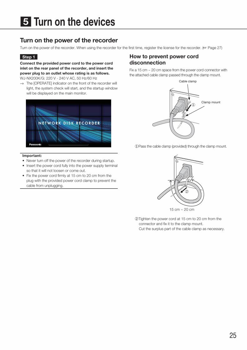
5 Turn on the devicesTurn on the power of the recorderTurn on the power of the recorder. When using the recorder for the first time, register the license for the recorder. (☞ Page 27)
Step 1Connect the provided power cord to the power cord inlet on the rear panel of the recorder, and insert the power plug to an outlet whose rating is as follows.WJ-NX200K/G: 220 V - 240 V AC, 50 Hz/60 Hz
→→ The [OPERATE] indicator on the front of the recorder will light, the system check will start, and the startup window will be displayed on the main monitor.
Important:• Never turn off the power of the recorder during startup.• Insert the power cord fully into the power supply terminal
so that it will not loosen or come out.• Fix the power cord fi rmly at 15 cm to 20 cm from the
plug with the provided power cord clamp to prevent the cable from unplugging.
How to prevent power cord disconnectionFix a 15 cm ~ 20 cm space from the power cord connector with the attached cable clamp passed through the clamp mount.
①Clamp mount
Cable clamp
① Pass the cable clamp (provided) through the clamp mount.
②
15 cm ~ 20 cm
② Tighten the power cord at 15 cm to 20 cm from the connector and fix it to the clamp mount.Cut the surplus part of the cable clamp as necessary.

26
5 Turn on the devices (continued)
Step 2The administration registration window is displayed on the main monitor.
Enter an administrator, a password and a password confir-mation following the instruction on the display, and click [Registration].Clicking [OK] on the displayed confirmation screen completes the administration registration.
Important:• Change the password periodically.
Precautions on storing the administrator name and the password
If you forget the set administrator name and password, you need to initialize* the recorder. Once the recorder is initialized, all the settings are deleted. Keep informa-tion on the administrator name and the password in a safe place where nobody can see it except you.* Contact your dealer for initializing.
Step 3If the license for the recorder has not been registered yet, the message asking you to register the "Registration Key" will be displayed after the completion of the system check and the administrator registration.
If the "Registration Key" for the recorder has not been regis-tered yet, register the "Registration Key" by following the procedures on page 27.
Note:• If the "Registration Key" for the recorder is once regis-
tered, the message asking you to register the "Registration Key" will not be displayed from the next time.
(When turn off the power of the recorder)Follow the procedure below to turn off the power.
Step 1During recording, set "Recording mode" on [Advanced setup] tab under "REC & event" under [Basic Setup] from Setup menu to "Off" to stop all recordings. (☞ Operating Instructions (PDF))
Step 2Unplug the power plug from the power outlet after confirming that the [REC] indicator is off.
→→ [OPERATE] indicator on the front of the recorder will go off.
Important:• Remove the plug from the outlet if not operating the recorder for a long period.
Note:• Be sure to perform the operation to start recording (select "On" for "Recording mode") after turning on the power
of the recorder again.

27
→→ The setup menu will be displayed.
Step 4Click [Advanced setup] - [Maintenance] - the [System management] tab on the setup menu.
→→ The "System management" page will be displayed.
When using the recorder for the first time, using the secure function, or increasing the number of the cameras to be connected, it is necessary to register the recorder license (Registration Key).
Important:• In the following cases, the recorder must be rebooted by clicking the [Restart] button. The licenses will not be effective until
the recorder is rebooted.• When the Registration Key of the recorder is registered• When the license of the additional camera kit or the additional business intelligence kit is added
• The added cameras shall be registered on "Easy start" (☞ page 29) or on the "Camera registration" tab. Each setting value is the default. Configure each setting according to your needs.
Step 1Obtain the "Registration Key" for the recorder by fol-lowing the instructions on the provided "Activation Key Card".To use each extra function, get the "Registration Key" of each additional license according to the appropriate Additional kit (option).Refer to the "Activation Key Card" for further information.
Step 2Start the recorder. (☞ Page 25)
→→ When the system check is complete, the operational screen will be displayed on the main monitor.
Step 3Click the [Setup] button.
6 Register the license (Registration Key)

28
Step 5Click the [Setup >] button of [Registration of license (This product, camera extension, etc.)].
→→ The registration window will be displayed.
Step 6Click the [Registration >] button of "Product" - "Registration Key".
→→ The "Registration key input" window will be displayed.
Step 7Enter the "Registration key" for the recorder in the "Registration key" field using the on-screen keyboard, and click the [Registration] button.
→→ The "Registration key input" window will return to the registration window.
Note:• When an error message is displayed, enter the effective
"Registration Key" again on the entry fi eld.
Step 8To increase the number of connected cameras, enter the registration key of the additional camera license obtained in step 1 to the "Registration Key 1-3" fields under "Additional camera" on the "Registration of license" page shown in step 5.To use the business intelligence function, enter the "Registration Key" following "How to register the license" in the user manual of the additional business intelligence kit.To use the secure function, click the [Setup >] button of [Registration of license (Security)] under the system management screen shown in Step 4, and then enter the registration key of the secure communication license obtained in Step 1 in the "Registration Key 1-32" fields under "Secure communication" on the "Registration of license" page.The operations are the same as those of Step 6 and 7.
Note:• Register the registration key for the recorder fi rst, and
then for each additional licenses.
Step 9Click the [Restart] button on the registration window to register the license.
→→ The recorder will reboot and each license will become effective.
6 Register the license (Registration Key) (continued)
29
[Time]Set the current time.
Step 3Click the [Apply] button after setting the date & time.
→→ The second will be set to "00".
[Set time zone]Select your time zone.
GMT-12:00 - GMT+13:00Default: GMTMarking the checkbox for [Activate the Daylight saving time] will active daylight saving time.
Step 4Click the [Next] button.
→→ The camera registration window opens.
Note:• To use the existing IP address of the connected cameras,
refer to "Detect cameras for registration [Detect cameras]" (☞ Operating Instructions (PDF)) instead of "Easy start".
• Before the settings, register the cameras into the net-work. Only the cameras added by license registration will be detected even though more cameras than the regis-tered license number are connected.
It is recommended to disconnect unnecessary cameras.• Cameras shall be connected to the Camera/PC port.
Cameras will not be detected if they are connected to the PC port.
Step 5Register the cameras connected to the recorder.
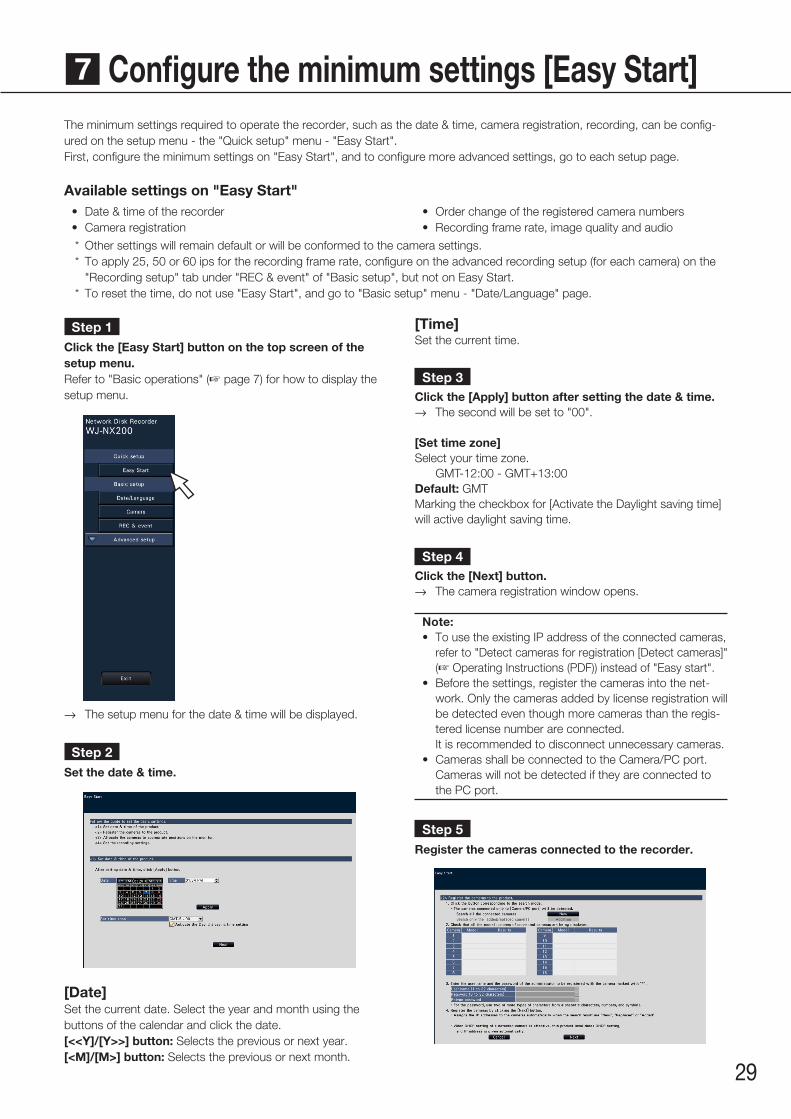
The minimum settings required to operate the recorder, such as the date & time, camera registration, recording, can be config-ured on the setup menu - the "Quick setup" menu - "Easy Start".First, configure the minimum settings on "Easy Start", and to configure more advanced settings, go to each setup page.
Available settings on "Easy Start"
Step 1Click the [Easy Start] button on the top screen of the setup menu.Refer to "Basic operations" (☞ page 7) for how to display the setup menu.
→→ The setup menu for the date & time will be displayed.
Step 2Set the date & time.
[Date]Set the current date. Select the year and month using the buttons of the calendar and click the date.[<<Y]/[Y>>] button: Selects the previous or next year.[<M]/[M>] button: Selects the previous or next month.
• Date & time of the recorder• Camera registration
• Order change of the registered camera numbers• Recording frame rate, image quality and audio
* Other settings will remain default or will be conformed to the camera settings. * To apply 25, 50 or 60 ips for the recording frame rate, configure on the advanced recording setup (for each camera) on the
"Recording setup" tab under "REC & event" of "Basic setup", but not on Easy Start. * To reset the time, do not use "Easy Start", and go to "Basic setup" menu - "Date/Language" page.
7 Configure the minimum settings [Easy Start]
30
Step 7Click the [Next] button.
→→ IP address will be given to the cameras newly con-nected, replaced or added, and the images from the camera will be displayed on the operational screen.
Note:• On "Easy Start", it is impossible to register the camera in
a different network via the same router.• For the security enhancement, changing of the IP
address of the camera will become impossible when 20 minutes have passed after the power is turned on. Perform the camera detection within 20 minutes, or turn off the power of the camera and turn it on again if more than 20 minutes has passed. Refer to the operating instructions of the camera for further information.
When 20 minutes have passed after the power of the camera is turned on, "ONVIF" may be detected depend-ing on the models of Panasonic cameras. In such a case, turn off the power of the camera and turn if on again to perform the camera detection.
• When "On" is selected for the "DHCP" setting of the detected cameras, the recorder will forcibly change the setting to "Off" to give the IP addresses automatically.
• When the [Cancel] button is clicked, the top screen of "Easy Start" (the menu to set the date & time) without applying the camera detection result will be displayed.
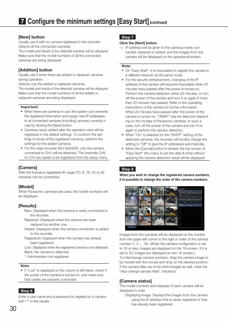
Step 8When you wish to change the registered camera numbers, it is possible to change the order of the camera numbers.
Images from the cameras will be displayed on the monitor from the upper left corner to the right in order of the camera number (1, 2 ... 16). (When the camera configuration is set to 16 or less, images are displayed on the 16-screen. If it is set to 32, images are displayed on two 16-screen.)To interchange camera numbers, drag the camera image to be moved with the mouse and drop on the desired position.If the camera titles are to be interchanged as well, mark the "Also change camera titles" checkbox.
[Camera status]The model numbers and statuses of each camera will be displayed in a list.
Displaying image: Displays the images from the camera using the IP address that is newly registered or that has already been registered.
[New] buttonUsually use it with no camera registered in the recorder.Detects all the connected cameras.The models and results of the detected cameras will be displayed.Make sure that the model numbers of all the connected cameras are being displayed.
[Addition] buttonUsually use it when there are added or replaced cameras during operation.Detects only the added or replaced cameras.The models and results of the detected cameras will be displayed.Make sure that the model numbers of all the added or replaced cameras are being displayed.
Important:• When there are cameras in use, the system can overwrite
the registered information and assign new IP addresses to all connected cameras (including cameras currently in use) by clicking the [New] button.
• Cameras newly added after the operation start will be registered in the default settings. To conform the set-tings to those of the registered cameras, perform the settings for the added cameras.
• For the video encoder (WJ-GXE500), only the camera connected to CH1 will be detected. The channels CH2 to CH4 are needs to be registered from the setup menu.
[Camera]After the license is registered (☞ page 27), 9, 16, 24 or 32 cameras can be connected.
[Model]When Panasonic cameras are used, the model numbers will be displayed.
[Results]New: Displayed when the camera is newly connected to
the recorder.Replaced: Displayed when the camera has been
replaced by another one.Added: Displayed when the camera connection is added
to the recorder.Registered: Displayed when the camera has already
been registered.Lost: Displayed when the registered camera is not detected.Blank: No camera is detected.*: Administrator not registered
Note:• If "Lost" is displayed or the column is left blank, check if
the power of the camera is turned on, and make sure that cables are properly connected.
Step 6Enter a user name and a password to register for a camera with "*" in the results.
7 Configure the minimum settings [Easy Start] (continued)
31
Changing IP address: Images are being obtained from the camera whose IP address has been changed.
Undetectable: Cannot obtain images from the camera.Authentication error: Failed in the authentication to dis-
play images from the camera.
Important:• If "Undetectable" is displayed, check the camera con-
nections, and retry the camera registration.• If "Authentication error" is displayed, initialized the cam-
era and retry the camera registration by referring to the operating instruction of the camera.
• If the registered camera is not correctly detected or if you wish to change the camera settings, change the registered information on the "Basic setup" menu - the "Camera" page - the "Camera registration" tab. (☞ Operating Instructions (PDF))
[Refresh] buttonObtain the latest camera image after interchanging cameras.
[Exit] buttonExits the setup menu and returns to the top screen of the setup menu.
[Next] buttonProceeds to the settings for recording.
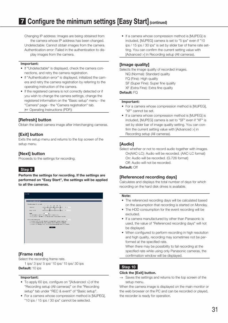
Step 9Perform the settings for recording. If the settings are performed on "Easy Start", the settings will be applied to all the cameras.
[Frame rate]Select the recording frame rate. 1 ips/ 3 ips/ 5 ips/ 10 ips/ 15 ips/ 30 ipsDefault: 10 ips
Important:• To apply 60 ips, configure on "[Advanced >] of the
"Recording setup (All cameras)" on the "Recording setup" tab under "REC & event" of "Basic setup".
• For a camera whose compression method is [MJPEG], "10 ips / 15 ips / 30 ips" cannot be selected.
• If a camera whose compression method is [MJPEG] is included, [MJPEG] camera is set to "5 ips" even if "10 ips / 15 ips / 30 ips" is set by slider bar of frame rate set-ting. You can confirm the current setting value with [Advanced >] in Recording setup (All cameras).
[Image quality]Selects the image quality of recorded images.
NQ (Normal): Standard qualityFQ (Fine): High qualitySF (Super Fine): Super fine qualityXF (Extra Fine): Extra fine quality
Default: FQ
Important:• For a camera whose compression method is [MJPEG],
"XF" cannot be set.• If a camera whose compression method is [MJPEG] is
included, [MJPEG] camera is set to "SF" even if "XF" is set by slider bar of image quality setting. You can con-firm the current setting value with [Advanced >] in Recording setup (All cameras).
[Audio]Select whether or not to record audio together with images.
On(AAC-LC): Audio will be recorded. (AAC-LC format)On: Audio will be recorded. (G.726 format)Off: Audio will not be recorded.
Default: Off
[Referenced recording days]Calculates and displays the total number of days for which recording on the hard disk drives is available.
Note:• The referenced recording days will be calculated based
on the assumption that recording is started on Monday.• The HDD consumption for the event recording will be
excluded.• If a camera manufactured by other than Panasonic is
used, the value of "Referenced recording days" will not be displayed.
• When configured to perform recording in high resolution and high quality, recording may sometimes not be per-formed at the specified rate.
When there may be possibility to fail recording at the specified rate while using only Panasonic cameras, the confirmation window will be displayed.
Step 10Click the [Exit] button.
→→ Saves the settings and returns to the top screen of the setup menu.
When the camera image is displayed on the main monitor or the web browser on the PC and can be recorded or played, the recorder is ready for operation.
7 Configure the minimum settings [Easy Start] (continued)

32
Before asking for repairs, check the symptoms with the following table.Contact your dealer if a problem cannot be solved even after checking and trying the solution in the table or a problem is not described below.
Symptom Cause/solution Ref. pages
Power is not turned on. • Is the power plug connected to the outlet firmly? Confirm the cable is firmly connected.
−
• Check if the power cord is properly inserted into the power socket of the recorder.
Check if it is connected firmly.
Important Information
Camera images are not displayed on the monitor
• Is the lens cap of the camera detached from the camera? Check whether the lens cap is removed.
−
• Is the power of the camera and connected devices on? Check whether the power is supplied to the camera and the
devices.
−
• Confirm that the cables are connected correctly and firmly. Confirm the cables are firmly connected.
16, 17
• Is the monitor luminance appropriately adjusted, or is the contrast appropriately adjusted?
Check whether the settings are appropriate.
−
• Users who have logged into the system may not be authorized to display the images from cameras.
Check the user level settings of these users.
Operating Instructions
Part of the displayed image is missing.
• This phenomenon is caused by dispersion of display area on the monitor. This is not a malfunction.
−
• When a function to automatically enlarge the images in the con-nected monitor is enabled, some part of the images may not be displayed depending on the photographic subject.
−
Image is blurred. • Is the lens of the camera soiled with dirt or dust? Check whether the lens of the camera is clean.
−
Cannot open the setup menu. • Users who have logged into the system may not be authorized to display the setup menu.
Check the user level settings of these users.
Operating Instructions
• Isn’t it the sub monitor you are currently operating? The setup menu cannot be displayed on the sub monitor.
17
The images or embedded characters displayed on the monitor look blurry.
• Depending on the photographic subject or HDMI monitor that is connected, images or embedded characters may look blurry. This phenomenon is not trouble.
−
No alarm action is taken. • Check if alarm input signals are properly input to the ALARM/CONTROL connector at the rear panel.
20
• Are the settings of the alarm connector appropriate? Operating Instructions
• Is "Off" or "Recording only" selected for "Mode"? Check whether the settings are appropriate.
Operating Instructions
The "Communication error: Cam.cc" indication is displayed on the main monitor.("cc" indicates the camera number.)
• Confirm that the camera is connected correctly and firmly. Check the camera connection.
16
• If the connection is appropriate, the cable may be broken or the camera may be out of order. Contact the dealer.
−
Troubleshooting

33
Symptom Cause/solution Ref. pages
The "Thermal error" indication is displayed on the main monitor.
• Check if the fan is malfunctioning. Operating Instructions
• Check if the recorder ventilation holes or cooling fan are blocked, and also check for dust collected around the ventilation holes.
6
• The ambient operating temperature is +5 °C to +45 °C. The "Thermal error" is displayed based on the internal thermal informa-tion of the HDD. If the "Thermal error" indication is displayed, it is recommended to change the installation environment so that the ambient temperature is maintained at approx. +25 °C. When the "Thermal error" indication is displayed frequently, contact your dealer.
15
The clock of the recorder may keep bad time.
• The clock function of the recorder is accurate within ±30 seconds per month. To keep the correct recording, set the time periodically, or enable the auto time adjustment function on the rear panel terminal, or configure the system using the NTP function so as to keep the cor-rect current time.
–
[HDD] indicator lights/blinks red.
• The hard disk drive is faulty. Contact your dealer. –
"Error" indictor blinks red. • The system is out of order. Contact your dealer. –"Authentication error" of the camera is displayed.
• Initialize the camera and retry the camera registration upon referring to the operating instructions of the camera.
–
Inspect the power cord, power plug and connectors periodically.
Symptom Cause/solution Ref. pages
The power cord insulation is damaged. • The power cord, connector, or power plug is damaged. This may result in electric shock or a fire. Unplug the power plug from the AC outlet immediately, and
refer to qualified service personnel.
−The power cord, plug and connectors get hot during use.The power cord gets hot when bent or stretched.
Troubleshooting (continued)

34

35

© Panasonic Corporation 2017 Ls0417-1087 PGQX2169YA Printed in China
Panasonic Corporationhttp://www.panasonic.com
Panasonic Corporation Osaka, Japan
Authorised Representative in EU:
Panasonic Testing CentrePanasonic Marketing Europe GmbHWinsbergring 15, 22525 Hamburg, Germany
Disposal of Old Equipment and Batteries Only for European Union and countries with recycling systems
These symbols on the products, packaging, and/or accompanying documents mean that used electrical and electronic products and batteries must not be mixed with general household waste.For proper treatment, recovery and recycling of old products and used batteries, please take them to applicable collection points in accordance with your national legislation.By disposing of them correctly, you will help to save valuable resources and prevent any potential negative effects on human health and the environment.For more information about collection and recycling, please contact your local municipality.Penalties may be applicable for incorrect disposal of this waste, in accordance with national legislation.
Note for the battery symbol (bottom symbol)This symbol might be used in combination with a chemical symbol. In this case it complies with the requirement set by the Directive for the chemical involved.