Installation Guide V8 - WWHCS Cams Manuals/V8.2.InstallationGuide... · 2.6 GV-NET Card V3.0 ......
116
Before attempting to connect or operate this product, please read these instructions carefully and save this manual for future use. Installation Guide V8.2
Transcript of Installation Guide V8 - WWHCS Cams Manuals/V8.2.InstallationGuide... · 2.6 GV-NET Card V3.0 ......

Before attempting to connect or operate this product,please read these instructions carefully and save this manual for future use.
Installation Guide V8.2

© 2008 GeoVision, Inc. All rights reserved. Under the copyright laws, this manual may not be copied, in whole or in part, without the written consent of GeoVision. Every effort has been made to ensure that the information in this manual is accurate. GeoVision is not responsible for printing or clerical errors. GeoVision, Inc. 9F, No. 246, Sec. 1, Neihu Rd., Neihu District, Taipei, Taiwan Tel: +886-2-8797-8377 Fax: +886-2-8797-8335 http://www.geovision.com.tw Trademarks used in this manual: GeoVision, the GeoVision logo and GV series products are trademarks of GeoVision, Inc. Windows and Windows XP are registered trademarks of Microsoft Corporation. January 2008

Contents
Chapter 1 Video Capture Cards..........................................................1
1.1 GV-2004, 2008 ....................................................................................................2
1.2 GV-1120, 1240, 1480 ........................................................................................10
1.3 GV-650, GV-800 ................................................................................................17
1.4 GV-600 ..............................................................................................................21
1.5 GV-250 ..............................................................................................................25
1.6 Installing Drivers ................................................................................................29
1.7 Connecting Hardware Watchdog.......................................................................31
1.8 Comparison Chart..............................................................................................32
Chapter 2 Hardware Accessories ....................................................35 2.1 GV-Multi Quad Card ..........................................................................................36
2.2 GV-Hybrid DVR Card.........................................................................................39
2.3 GV-Loop Through Card .....................................................................................42
2.4 GV-DSP Card ....................................................................................................45
2.5 GV-A16 Card .....................................................................................................48
2.6 GV-NET Card V3.0 ............................................................................................50
2.7 GV-NET/IO Card V3.1 .......................................................................................53
2.8 GV-IO 12-In Card V3 .........................................................................................62
2.9 GV-IO 12-Out Card V3 ......................................................................................65
2.10 GV-NET Box ......................................................................................................68
2.11 GV-IO USB Box .................................................................................................70
2.12 GV-Hub Box.......................................................................................................76
2.13 GV-COM Box.....................................................................................................80
2.14 GV-Data Capture V2 Box ..................................................................................83
2.15 GV-Data Capture V2E Box ................................................................................83
2.16 GV-Data Capture V3 Series ..............................................................................84
2.17 GV-Keyboard .....................................................................................................84
2.18 GV-Joystick........................................................................................................85
2.19 GV-IR Remote Control.......................................................................................85
2.20 GV-Wiegand Capture Box .................................................................................85
2.21 GV-Video Server................................................................................................86
i

ii
2.22 GV-Compact DVR .............................................................................................86
2.23 Installing USB Driver..........................................................................................87
Chapter 3 Software Installation ........................................................89 3.1 Before You Start ................................................................................................90
3.2 Installing the System..........................................................................................91
3.3 Program List ......................................................................................................93
Chapter 4 Screen Overview..............................................................95 4.1 Main System......................................................................................................96
4.2 ViewLog .............................................................................................................98
4.3 Remote Playback Client ..................................................................................102
4.4 SingleView MPEG4 Encoder Viewer ...............................................................104
4.5 MultiView MPEG4 Encoder Viewer .................................................................105
4.6 Remote Playback on WebCam........................................................................107
4.7 Center V2.........................................................................................................108
4.8 Control Center Toolbar ....................................................................................110
Troubleshooting .................................................................................111

Chapter 1 Video Capture Cards
This chapter includes the following information:
• Minimum system requirements
• Packing list
• Connection diagrams
• Specifications
• Driver installation
• Comparison chart

1.1 GV-2004, 2008 The GV-2004 and GV-2008, as four-in-one combo cards, include the features of previous GV-Video Capture Card (recording of up to 16 video channels), GV-DSP Card (real-time display), GV-A16 Card (recording of up to 16 audio channels), and GV-Hybrid DVR Card (hardware compression). This economic device not only provides a single-card solution but also saves the PCI slots.
Minimum System Requirements
OS Windows 2000 / Windows XP / Windows Server 2003 / Windows Vista
GV-2004 Pentium 4-2.4 GHz with Hyper-Threading GV-2008 Pentium 4-2.6 GHz with Hyper-Threading
CPU
GV-2008 x 2 Pentium 4-3.0 GHz with Hyper-Threading
GV-2004 2 x 512 MB Dual Channel
GV-2008 2 x 512 MB Dual Channel
RAM
GV-2008 x 2 2 x 1 GB Dual Channel
GV-2004 120 GB or above
GV-2008 250 GB or above
HDD
GV-2008 x 2 500 GB or above
VGA ATI Radeon 9550 or above NVIDIA 6200 or above
DirectX 9.0 or above
Note: 1. Currently GV-Video Capture Cards are not compatible with VIA-series and ATI-
series chipset motherboards. 2. To install two GV-2008 Cards, ensure the PC power supply is 400 Watts or above.
Packing List
1. GV-2004 or GV-2008 Card x 1
2. 1-4 D-Type Video and Audio Cable x 1
3. 5-8 D-Type Video and Audio Cable x 1
(only supplied with the GV-2008 Card)
4. 6-Pin Cable x 1
(only supplied with the GV-2008 Card)
5. Hardware Watchdog Jumper Wire x1
6. Software CD x 1
7. Feature Guide x 1
8. Installation Guide x 1
2

Video Capture Cards 1
Connections (GV-2004)
• Connect the D-Type video and audio cable to the GV-2004 Card. • Connect the TV Monitor to the GV-2004 Card if needed.
TV Monitor
Video 1~4
GV-2004 Card1
1-4 D-Type Video and Audio Cable
Audio 1~4
2
Figure 1-1 GV-2004 Card connections
3

Connections (GV-2008)
For the GV-2008 Card, you can choose to install one or two GV-2008 Cards to meet your different needs. Connect the D-Type video and audio cable to the GV-2008 Card. If needed, connect the TV monitor to the GV-2008 Card. When you install two GV-2008 Cards in a computer, you need to classify them as a master and a slave card. Insert them to their own slots determined by the PCI slot IDs. Use the 6-pin cable to connect the slave card to the master card. See Figure 1-3.
TV MonitorVideo 1~4
GV-2008 Card (Master)1
D-Type Video and Audio Cable
2
1
6
6-Pin Cable
Audio 5~8
Video 5~8
Audio 1~4
D-Type Video and Audio Cable
2Video 9-12
Audio 9-12
Audio 13-16
Video 13-16
2
(See the next page)
GV-2008 Card (Slave)
Figure 1-2 Connections of Two GV-2008 Cards
4

Video Capture Cards 1
Connecting Slave Card to Master Card
• The card attached to the lower PCI slot number will act as Master, and the card attached to the higher PCI slot number will act as Slave.
• Connect both cards’ inner pins with the 6-Pin Cable. See (A) connection in the Figure below.
• In a computer where two GV-2008 Cards are installed, only 8 channels are functional when the GV-System is running. It may be that the position of Master card and Slave card is reversed, so the 6-Pin Cable is connected to the wrong pin assignment. To solve the problem, please try to connect both cards’ outer pins with the 6-Pin Cable. See (B) connection in the Figure below.
Master CardSlave Card
Inner Outer
(A) 6-Pin Cable
Outer Inner
(B) 6-Pin Cable
Figure 1-3 Connecting the slave card to the master card
5

Adjusting the Video Settings in the Main System
One distinct feature of GV-2004 and GV-2008 Cards is their ability of hardware compression, providing you with higher system performance and DVD recording quality. To take full advantage of GV-2004 and GV-2008 Cards, you can adjust the video settings, including the codec, video resolution and frame rate, before running the GV-System.
Set the video settings of the recorded files:
Considering computer performance or recording quality, you may adjust the settings to meet your needs.
1. On the Main System, click the Configure button, point to General Setting, select Camera / Audio Install, and click Hybrid Camera Install. This dialog box appears.
Figure 1-4
2. Check the cameras you want to set up, and click the Configure button. This dialog box appears.
Figure 1-5
6

Video Capture Cards 1
3. In the Select Hybrid Camera field, select one camera to be configured.
4. Select the desired codec, video attributes, recording quality and video resolution. If you want to apply the same setting to all selected cameras, click the Finger button in each field. However, the codec selection applies to all cameras. If you change the codec selection when you configure another camera, the newly selected codec will replace the previous selection.
5. The Enable compressed data FIFO option is enabled by default. The hardware-compressed data from the video IP device, such as IP camera, video server and compact DVR, will be transmitted directly to remote servers instead of being compressed again on the DVR. The remote servers include CMS-related servers and WebCam Server. This feature can decrease the system load of DVR but increase that of remote servers.
6. To access the frame rate settings, on the Main System, click the Configure button, point to General Setting, select System Configure, and then click the Camera Record Setting tab. In the Rec Control section, click the Arrow button. The Hardware Rec. Frame Rate Setting dialog box appears.
Figure 1-6
7

7. Set the maximum frame rate for motion and non-motion periods so as to save as much disk space as possible.
Note:
1. The default settings are as follows: Record Quality is 3, Video Resolution is
720 x 480 (NTSC) or 720 x 576 (PAL), Codec is MPEG 4 (ASP) and Frame Rate is 30 (NTSC) or 25 (PAL).
2. When the Codec is set at MPEG-2 on GV-System V8.2, the Frame Rate is fixed at 30, and the Economic Round-the-Clock function cannot be used.
8

Video Capture Cards 1
Specifications
GV-2004 GV-2008 GV-2008 x 2
Input Type
DB 15 x 1
(for Video and Audio)
DB 15 x 2
(for Video and Audio)
DB 15 x 4
(for Video and Audio)
Video Input 4 Cams 8 Cams 16 Cams
TV Output RCA Connector x 1
Audio Input 4 Channels 8 Channels 16 Channels
120 fps (NTSC) 240 fps (NTSC) 480 fps (NTSC) S/W
(CIF) 100 fps (PAL) 200 fps (PAL) 400 fps (PAL)
120 fps (NTSC) 240 fps (NTSC) 480 fps (NTSC) Recording Rate
H/W
(D1 or Half D1) 100 fps (PAL) 200 fps (PAL) 400 fps (PAL)
NTSC 120 fps 240 fps 480 fps Display Rate
PAL 100 fps 200 fps 400 fps
NTSC 720 x 480, 720 x 480 (De-interlace) Video Resolution
PAL 720 x 576, 720 x 576 (De-interlace)
S/W Geo MPEG4, Geo MPEG4 (ASP), Geo H264,
Geo H264 V2 Compression Format
H/W MPEG-2, MPEG-4 (ASP)
GV-NET/IO Card Support Yes
Dimensions (W x H) 195 mm x 102 mm 240 mm x 102 mm
9

1.2 GV-1120, 1240, 1480 GV-1120, GV-1240 and GV-1480 are the three-in-one combo cards, providing one single card solution for 16 video / audio recording, real-time display and TV-out display. To meet different needs, there are three types of GV-Combo cards: D-Type, DVI Type and PCI-E.
Minimum System Requirements
OS Windows 2000 / Windows XP / Windows Server 2003 / Windows Vista
GV-1120 Pentium 4-2.4 GHz with Hyper-Threading
GV-1240 Pentium 4-2.6 GHz with Hyper-Threading CPU
GV-1480 Pentium 4-3.0 GHz with Hyper-Threading
RAM 2 x 512 MB Dual Channel
GV-1120 80 GB
GV-1240 120 GB HDD
GV-1480 250 GB
VGA ATI Radeon 9550 or above
NVIDIA 6200 or above
DirectX 9.0 or above
Note: Currently GV-Video Capture Cards are not compatible with VIA-series and ATI-series chipset motherboards.
Packing List (D-Type and PCI-E)
1. GV-1120/1240/1480 Combo Card x 1
2. Audio Extension Card x 1
3. 1-8 D-Type Video Cable x 1
4. 9-16 D-Type Video Cable x 1
5. 1-8 D-Type Audio Cable x 1
6. 9-16 D-Type Audio Cable x 1
7. Hardware Watchdog Jumper Wire x 1
8. Software CD x 1
9. Feature Guide x 1
10. Installation Guide x1
10

Video Capture Cards 1
Packing List (DVI Type)
1. GV-1120/1240/1480 Combo Card x 1
2. 1-16 DVI Video plus TV Out Cable x 1
3. 1-16 DVI Audio Cable x 1
4. Hardware Watchdog Jumper Wire x 1
5. Software CD x 1
6. Feature Guide x 1
7. Installation Guide x1
Connections (D-Type)
• Plug the Audio Extension Card in the assigned connectors on the GV-Combo Card.
• Connect D-Type video and audio cables to the GV-Combo Card and Audio Extension Card respectively.
• Connect the TV monitor to the GV-Combo Card if needed.
1
23
4
12
34
Video 1~8
Video 9~16
Audio 1~8
Audio 9~16
TV Monitor
Extension Audio Card2
GV-Combo Card1
1-8 D-Type Video Cable
3
9-16 D-Type Video Cable
4
1-8 D-Type Audio Cable
5
9-16 D-Type Audio Cable
6
Figure 1-7 GV-Combo Card (D-Type) connections
11

Specifications (D-Type)
GV-1120 GV-1240 GV-1480
Input Type DB15 x 2 (Video), DB9 x 2 (Audio)
Video Input 8, 12, 16 Cams 8, 16 Cams 16 Cams
Audio Input 8, 12, 16 Channels 8, 16 Channels 16 Channels
TV Output RCA Connector x 1
NTSC 120 fps 240 fps 480 fps Recording Rate
(At 320 x 240 Resolution) PAL 100 fps 200 fps 400 fps
NTSC 480 fps Display Rate
PAL 400 fps
NTSC 720 x 480, 720 x 480 De-interlace, 640 x 480, 640 x 480 De-interlace, 360 x 240, 320 x 240
Video Resolution
PAL 720 x 576, 720 x 576 De-interlace, 640 x 480, 640 x 480 De-interlace, 360 x 288, 320 x 240
Compression Format Geo MPEG4, Geo MPEG4 (ASP), Geo H264, Geo H264 V2
GV-NET/IO Card Support Yes
GV-Hybrid DVR Card Support Yes
Dimensions (W x H) 170 mm x 95 mm
12

Video Capture Cards 1
Connections (PCI-E)
• Plug the Audio Extension Card in the assigned connectors on the GV-Combo Card.
• Connect D-Type video and audio cables to the GV-Combo Card and Audio Extension Card respectively.
• Plug the power cable connector in the GV-Combo Card’s power connector.
• Connect the TV monitor to the GV-Combo Card if needed.
TV Monitor
Extension Audio Card2
1
2
3
4
1 2
3 4
Video 1~8
Video 9~16
Audio 1~8
Audio 9~16
GV-Combo Card1
1-8 D-Type Video Cable
3
9-16 D-Type Video Cable
4
1-8 D-Type Audio Cable
5
9-16 D-Type Audio Cable
6
Connects to PC's Power Supply
Figure 1-8 GV-Combo Card (PCI-E) connections
Note: 1. The GV-Combo Card (PCI-E) has PCI Express x 1 interface, and it can be inserted
into the PCI Express x1, x4, x8 or x16 slot.
2. This card only works when it connects to PC’s power supply.
13
Specifications (PCI-E)
GV-1120 GV-1240 GV-1480
Input Type DB15 x 2 (Video), DB9 x 2 (Audio)
Video Input 8, 12, 16 Cams 8, 16 Cams 16 Cams
Audio Input 8, 12, 16 Channels 8, 16 Channels 16 Channels
TV Output RCA Connector x 1
NTSC 120 fps 240 fps 480 fps Recording Rate
(At 320 x 240 Resolution) PAL 100 fps 200 fps 400 fps
NTSC 480 fps Display Rate
PAL 400 fps
NTSC 720 x 480, 720 x 480 De-interlace, 640 x 480, 640 x 480 De-interlace, 360 x 240, 320 x 240
Video Resolution
PAL 720 x 576, 720 x 576 De-interlace, 640 x 480, 640 x 480 De-interlace, 360 x 288, 320 x 240
Compression Format Geo MPEG4, Geo MPEG4 (ASP), Geo H264, Geo H264 V2
GV-NET/IO Card Support Yes
GV-Hybrid DVR Card Support Yes
Dimensions (W x H) 212 mm x 99 mm
14

Video Capture Cards 1
Connections (DVI-Type)
• Connect the DVI video and audio cables to the GV-Combo Card.
• Connect the DVI TV Out cable to the TV monitor if needed.
TV Monitor
GV-Combo Card
1-16 DVI Video Cable
1-16 DVI Audio Cable
DVI TV Out Cable
1
3
2
2
Figure 1-9 GV-Combo Card (DVI-Type) connections
15

Specifications (DVI-Type)
GV-1120 GV-1240 GV-1480
Input Type DVI x 1 (for Video), DVI x 1 (for Audio)
Video Input 8, 12, 16 Cams 8, 16 Cams 16 Cams
Audio Input 8, 12, 16 Channels 8, 16 Channels 16 Channels
TV Output RCA Connector x 1
NTSC 120 fps 240 fps 480 fps Recording Rate (At 320 x 240 Resolution) PAL 100 fps 200 fps 400 fps
NTSC 480 fps Display Rate
PAL 400 fps
NTSC 720 x 480, 720 x 480 De-interlace, 640 x 480, 640 x 480 De-interlace, 360 x 240, 320 x 240
Video Resolution
PAL 720 x 576, 720 x 576 De-interlace, 640 x 480, 640 x 480 De-interlace, 360 x 288, 320 x 240
Compression Format Geo MPEG4, Geo MPEG4 (ASP), Geo H264, Geo H264 V2
GV-NET/IO Card Support Yes
GV-Hybrid DVR Card Support Yes
Dimensions (W x H) 165 mm x 95 mm
16

Video Capture Cards 1
1.3 GV-650, GV-800 The GV-650 and GV-800 Cards have similar appearances, system requirements and packing list so that we introduce both together in this section. However, you may choose between the two according to your need for recording rate and audio channels.
Minimum System Requirements
OS Windows 2000 / Windows XP / Windows Server 2003 / Windows Vista
CPU Pentium 4-2.4 GHz with Hyper-Threading
RAM 2 x 512 MB Dual Channel
HDD 80 GB
VGA ATI Radeon 9550 or above NVIDIA 6200 or above
DirectX 9.0 or above
Note: Currently GV-Video Capture Cards are not compatible with VIA-series and ATI-series chipset motherboards.
Packing List
1. GV-800 or GV-650 Card x 1
2. Audio Extension Card x 1 **
3. 1-8 Cams with 4-Port Audio D-Type Cable x 1
4. 9-16 Cams D-Type Cable x 1 *
5. BNC Video Extension Card ***
(Quantity depends on model purchased)
6. Hardware Watchdog Jumper Wire x 1
7. Software CD x 1
8. Feature Guide x 1
9. Installation Guide x1
* Supplied with 12-16 Cams D-Type Video Capture Card ** Supplied with BNC Video Capture Card *** Supplied with 8-16 Cams BNC Video Capture Card
17
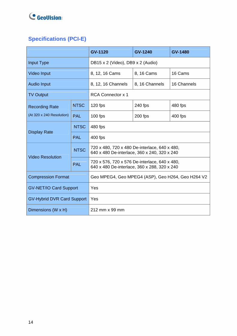
Connections
There are two types of GV-800 and GV-650 Cards: BNC and D-Type. BNC type only provides four video channels; video and audio extension cards are required for extension. D-Type can provide up to 16 video channels and four audio channels together. For the D-Type video capture card, plug the black video/audio cable into the black connector on the GV-650/800 Card; the blue video cable into the blue connector, as illustrated below.
Note: The GV-650 Card only supports two audio channels so that only two audio ports can work in the supplied 1-8 Cams with 4-Port Audio D-Type cable.
Video 1~8 (Black)
Audio 1~4 (White)
Video 9~16 (Blue)
GV-800/650 Card
1
4
3
3
Figure 1-10 D-Type GV-650 or GV-800 Card connections
18

Video Capture Cards 1
For the BNC-type video capture card, plug the Audio Extension Card into No. 1 or No. 2 connector on the GV-650/800 Card, as illustrated below. Both connectors are okay for connection.
Audio Extension Card
GV-800/650 Card
1
2
or
1
2
Figure 1-11 BNC-type GV-650 or GV-800 Card connections
19
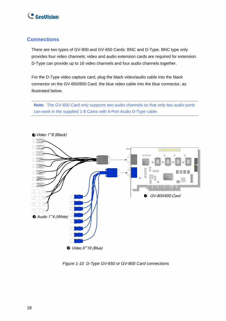
Specifications
GV-650 GV-800
BNC BNC x 4 Input Type
D-Type DB15 x 2
Video Input 4, 8, 12, 16 Cams
Audio Input 2 Channels 4 Channels
NTSC 60 fps 120 fps Recording Rate (At 320 x 240 Resolution) PAL 50 fps 100 fps
NTSC 60 fps 120 fps Display Rate
PAL 50 fps 100 fps
NTSC 720 x 480, 720 x 480 De-interlace, 640 x 480, 640 x 480 De-interlace, 360 x 240, 320 x 240
Video Resolution
PAL 720 x 576, 720 x 576 De-interlace, 640 x 480, 640 x 480 De-interlace, 360 x 288, 320 x 240
Compression Format Geo MPEG4, Geo MPEG4 (ASP), Geo H264, Geo H264 V2
GV-DSP Card Support Yes
GV-A16 Support Yes
GV-NET/IO Card Support Yes
GV-650/800 (S) 175 mm x 98 mm BNC
GV-650 (V4) 144 mm x 98 mm
GV-650/800 (S) 175 mm x 98 mm
GV-650 (V4) 144 mm x 98 mm
Dimensions (W x H)
D-Type
GV-800 (V4) 174 mm x 98 mm
20
Video Capture Cards 1
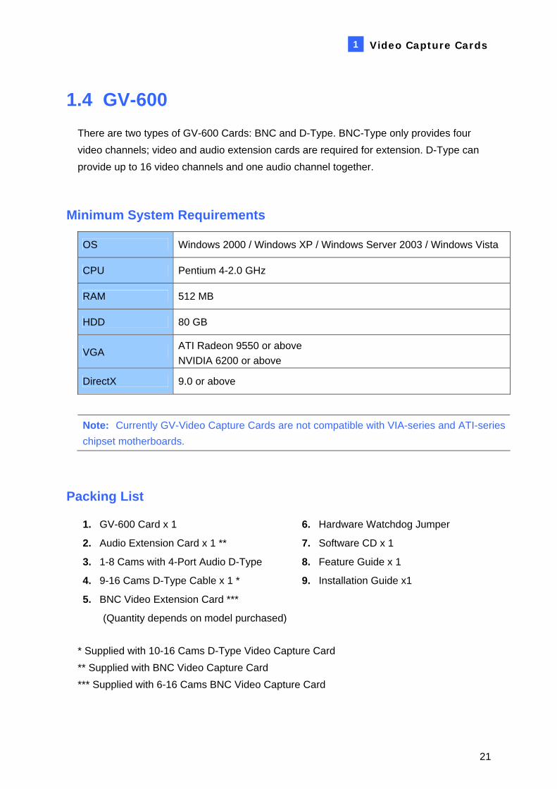
1.4 GV-600 There are two types of GV-600 Cards: BNC and D-Type. BNC-Type only provides four video channels; video and audio extension cards are required for extension. D-Type can provide up to 16 video channels and one audio channel together.
Minimum System Requirements
OS Windows 2000 / Windows XP / Windows Server 2003 / Windows Vista
CPU Pentium 4-2.0 GHz
RAM 512 MB
HDD 80 GB
VGA ATI Radeon 9550 or above NVIDIA 6200 or above
DirectX 9.0 or above
Note: Currently GV-Video Capture Cards are not compatible with VIA-series and ATI-series chipset motherboards.
Packing List
1. GV-600 Card x 1
2. Audio Extension Card x 1 **
3. 1-8 Cams with 4-Port Audio D-Type
4. 9-16 Cams D-Type Cable x 1 *
5. BNC Video Extension Card ***
(Quantity depends on model purchased)
6. Hardware Watchdog Jumper
7. Software CD x 1
8. Feature Guide x 1
9. Installation Guide x1
* Supplied with 10-16 Cams D-Type Video Capture Card ** Supplied with BNC Video Capture Card *** Supplied with 6-16 Cams BNC Video Capture Card
21

Connections
For the D-Type video capture card, plug the black video/audio cable into the black connector on the GV-600 Card; the blue video cable into the blue connector, as illustrated below.
Note: The GV-600 Card only supports one audio channel so that only one audio port can work in the supplied 1-8 Cams with 4-Port Audio D-Type cable.
Video 1~8 (Black)
Audio 1~4 (White)
Video 9~16 (Blue)
GV-600 Card
1
3
3
4
Figure 1-12 D-Type GV-600 Card connections
22

Video Capture Cards 1
For the BNC-Type video capture card, plug the Audio Extension Card into No. 1 or No. 2 connector on the GV-600 Card, as illustrated below. Both connectors are okay for connection.
Audio Extension Card
GV-600 Card
1
2or
1
2
Figure 1-13 BNC-Type GV-600 Card connections
23

Specifications
GV-600
GV-600 BNC: BNC x 4 Input Type
GV-600 D-Type: DB15 x 2
Video Input 1, 2, 4, 6, 8, 10, 12, 14, 16 Cams
Audio Input 1 Channel
NTSC 30 fps Recording Rate (At 320 x 240 Resolution) PAL 25 fps
NTSC 30 fps Display Rate
PAL 25 fps
NTSC 720 x 480, 720 x 480 De-interlace, 640 x 480, 640 x 480 De-interlace, 360 x 240, 320 x 240
Video Resolution
PAL 720 x 576, 720 x 576 De-interlace, 640 x 480, 640 x 480 De-interlace, 360 x 288, 320 x 240
Compression Format Geo MPEG4, Geo MPEG4 (ASP), Geo H264, Geo H264 V2
GV-DSP Card Support Yes
GV-A16 Support Yes
GV-NET/IO Card Support Yes
GV-Hybrid Card Support Yes
GV-600 (S) 145 mm x 97 mm BNC
GV-600 (V4) 144 mm x 89 mm
GV-600 (S) 145 mm x 97 mm Dimensions (W x H)
D-Type GV-600 (V4) 144 mm x 89 mm
24
Video Capture Cards 1
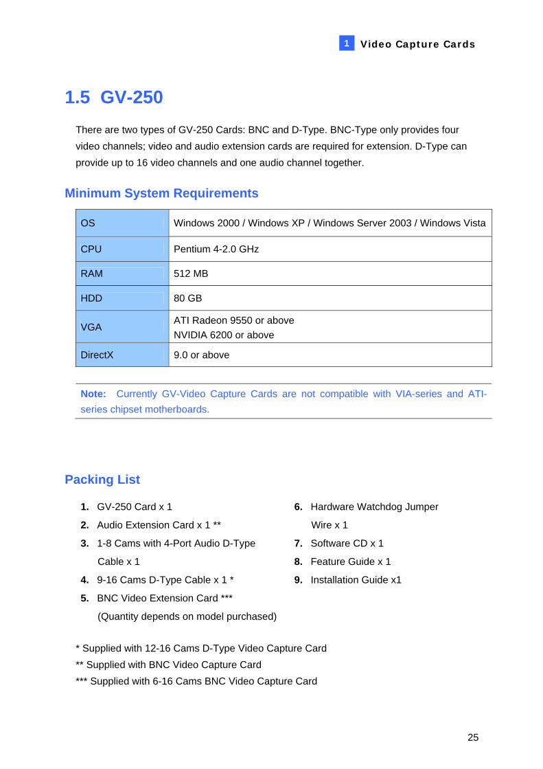
1.5 GV-250 There are two types of GV-250 Cards: BNC and D-Type. BNC-Type only provides four video channels; video and audio extension cards are required for extension. D-Type can provide up to 16 video channels and one audio channel together.
Minimum System Requirements
OS Windows 2000 / Windows XP / Windows Server 2003 / Windows Vista
CPU Pentium 4-2.0 GHz
RAM 512 MB
HDD 80 GB
VGA ATI Radeon 9550 or above NVIDIA 6200 or above
DirectX 9.0 or above
Note: Currently GV-Video Capture Cards are not compatible with VIA-series and ATI-series chipset motherboards.
Packing List
1. GV-250 Card x 1
2. Audio Extension Card x 1 **
3. 1-8 Cams with 4-Port Audio D-Type
Cable x 1
4. 9-16 Cams D-Type Cable x 1 *
5. BNC Video Extension Card ***
(Quantity depends on model purchased)
6. Hardware Watchdog Jumper
Wire x 1
7. Software CD x 1
8. Feature Guide x 1
9. Installation Guide x1
* Supplied with 12-16 Cams D-Type Video Capture Card ** Supplied with BNC Video Capture Card *** Supplied with 6-16 Cams BNC Video Capture Card
25

Connections
For the D-Type video capture card, plug the black video/audio cable into the black connector on the GV-250 Card; the blue video cable into the blue connector, as illustrated below.
Note: The GV-250 Card only supports one audio channel so that only one audio port can work in the supplied 1-8 Cams with 4-Port Audio D-Type cable.
Video 1~8 (Black)
Audio 1~4 (White)
Video 9~16 (Blue)
GV-2501
3
3
4
Figure 1-14 D-Type GV-250 Card connections
26

Video Capture Cards 1
For the BNC-Type video capture card, plug the Audio Extension Card into the connector on the GV-250 Card, as illustrated below.
Audio Extension Card
GV-250 Card
Figure 1-15 BNC-Type GV-250 Card connections
27

Specifications
GV-250
GV-250 BNC: BNC x 4 Input Type
GV-250 D-Type: DB15 x 2
Video Input 1, 2, 4, 6, 8,12,16 Cams
Audio Input 1 Channel
NTSC 15 fps Recording Rate (At 320 x 240 Resolution) PAL 12 fps
NTSC 15 fps Display Rate
PAL 12 fps
NTSC 720 x 480, 720 x 480 De-interlace, 640 x 480, 640 x 480 De-interlace, 360 x 240, 320 x 240
Video Resolution
PAL 720 x 576, 720 x 576 De-interlace, 640 x 480, 640 x 480 De-interlace, 360 x 288, 320 x 240
Compression Format Geo MPEG4, Geo MPEG4 (ASP), Geo H264, Geo H264 V2
GV-DSP Card Support Yes
GV-A16 Support No
GV-NET/IO Card Support No
BNC 120 mm x 95 mm Dimensions (W x H)
D-Type 120 mm x 87 mm
28

Video Capture Cards 1
1.6 Installing Drivers After you install the GV-Video Capture Card on the computer, the Found New Hardware Wizard will automatically detect the device. Ignore the wizard and follow these steps to install drivers:
1. Insert the software CD. It will run automatically and pop up a window.
2. Select Install or Remove GeoVision GV-Series Cards Driver. This dialog box appears.
Figure 1-16
3. Click Install to install the drivers. When the installation is complete, this message will appear: Install Successfully.
4. Click Exit to close the dialog box.
Note:
1. In Windows XP, the wizard will disappear after installation. In Windows 2000, close the wizard manually.
2. For the installation of two GV-2008 cards, it is required to restart the computer after the driver is installed.
29

To verify the drivers are installed correctly, go to Device Manager and see if the following entries are listed.
Expand the Sound, video and game controller field, you can see:
Model Entry
GV-250 GV250 Audio GV250 Video Capture
GV-600-4 GV600_4, GV604(S) Video Capture #A, or GV604(V4) Video Capture GV-600_4, GV604(S) Audio #A, or GV604(V4) Audio
GV-600 GV-600V2, GV600V3, GV600(S) Audio #A, or GV600(V4) Audio GV-600V2, GV600V3, GV600(S) Video Capture #A, or GV600(V4) Video Capture
GV-650
GV650, GV650V3, GV650(S) Audio #A - #B, or GV650(V4) Audio #1 - #2 GV650, GV650V3, GV650(S) Video Capture #A - #B, or GV650(V4) Video Capture #1 - #2
GV-800-4 GV-800_4, GV804(S) Video Capture #A - #D, or GV800_4A Video Capture #1 - #4 GV-800_4, GV804(S) Audio #A - #D, or GV800 Audio #1 - #4
GV-800
GV800V2, GV800V3, GV800(S) Audio #A - #D, or GV800(V4) Audio #1 - #4 GV800V2, GV800V3, GV800(S) Video Capture #A - #D, or GV800(V4) Video Capture #1 - #4
Expand the DVR-Devices field, you can see:
Model Entry
GV-1120 GV1480/GV1240/GV1248/GV1120 Driver
GV-1240 GV1480/GV1240/GV1248/GV1120 Driver
GV-1480 GV1480/GV1240/GV1248/GV1120 Driver
GV-2004 GV2004-MP4 (CAP), GV2004-MP4 (ENC)
GV-2008 GV2008-MP4 (CAP), GV2008-MP4 (ENC), GV2008-MP4 (ENC)
GV-2008 (2 GV-2008 Cards)
GV2008-MP4 (CAP), GV2008-MP4 (CAP), GV2008-MP4 (ENC), GV2008-MP4 (ENC), GV2008-MP4 (ENC), GV2008-MP4 (ENC)
30

Video Capture Cards 1
1.7 Connecting Hardware Watchdog To reboot the computer by the hardware watchdog on the GV-Video Capture Card, a connection needs to be made from the card to the motherboard.
1. Using the supplied jumper wire, connect the reset jumper pins on the card and on the motherboard.
GeoVision GV-600v2
GV-600 MotherboardFront Panel Jumper
PWSW
LEDHDD
PC Reset Switch
+ _
RST
Figure 1-17 Watchdog connections
2. If the computer has a reset switch, the switch’s jumper wire should already be connected to the motherboard’s reset jumper pins. Remove the switch wire from the motherboard and connect it to the reset jumper pins on the card.
31

1.8 Comparison Chart
GV-250 GV-600 GV-650 GV-800
Input Type BNC / D-Type BNC / D-Type BNC / D-Type BNC / D-Type
Video Input 1, 2, 4, 6, 8, 12, 16 1, 2, 4, 6, 8, 10, 12, 14, 16 4, 8, 12, 16 4, 8, 12, 16
NTSC 15 fps 30 fps 60 fps 120 fps Total Recording Rate (at 320 x 240) PAL 12 fps 25 fps 50 fps 100 fps
NTSC 15 fps 30 fps 60 fps 120 fps Display Rate
PAL 12 fps 25 fps 50 fps 100 fps
Video Codec Geo MPEG4, Geo MPEG4 (ASP), Geo H264, Geo H264 V2
NTSC 720 x 480, 720 x 480 De-interlace, 640 x 480, 640 x 480 De-interlace, 360 x 240, 320 x 240
Video Resolution PAL 720 x 576, 720 x 576 De-interlace, 640 x 480,
640 x 480 De-interlace, 360 x 288, 320 x 240
Audio Input 1 1 2 4
Audio Codec ADPCM 8Khz 4 bit Mono
GV-Multi Quad Card Support O O O O GV-DSP Support O O O O GV-A16 Support X O O O GV-Hybrid DVR Card Support X O O O GV-NET/IO Card Support X O O O GV-I/O 12-In Card Support X O O O GV-I/O 12-Out Card Support X O O O GV-I/O Support O O O O Hardware Watchdog X O O O
Minimum System Requirements
OS Windows 2000 / XP / Server 2003 / Vista
Direct X 9.0 or above
CPU Pentium 4 Pentium 4-2.4 GHz 2.0 GHz with Hyper-Threading
RAM 512 MB 2 x 512 MB Dual Channel
HDD 80 GB
VGA ATI Radeon 9550 or above / NVIDIA 6200 or above Note: 1. Currently GV-Video Capture Cards are not compatible with VIA-series and ATI-series chipset motherboards.2. For recording resolution of 640 x 480 or above, Pentium 4 processor with Hyper Threading is required. 3. For software recording rates, all GV cards are set to CIF. For hardware recording rates, GV-2004 and GV-
2008 Cards are set to D1 and Half D1.
32

Video Capture Cards 1
GV-1120 GV-1240 GV-1480 GV-2004 GV-2008 GV-2008 x 2
D-Type / PCI-E / DVI-Type D-Type
8, 12, 16 8, 16 16 4 8 16
120 fps 240 fps 480 fps 120 fps 240 fps 480 fps
100 fps 200 fps 400 fps 100 fps 200 fps 400 fps
480 fps 480 fps 480 fps 120 fps 240 fps 480 fps
400 fps 400 fps 400 fps 100 fps 200 fps 400 fps HW: MPEG-4 (ASP), MPEG-2 SW: Geo MPEG4, Geo MPEG4 (ASP), Geo MPEG4, Geo MPEG4 (ASP),
Geo H264, Geo H264 V2 Geo H264, Geo H264 V2
720 x 480, 720 x 480 De-interlace, 640 x 480, 640 x 480 De-interlace, 360 x 240, 320 x 240 720 x 480, 720 x 480 De-interlace
720 x 576, 720 x 576 De-interlace, 640 x 480, 640 x 480 De-interlace, 360 x 288, 320 x 240 720 x 576, 720 x 576 De-interlace
8, 12, 16 8, 16 16 4 8 16
ADPCM 8Khz 4 bit Mono
O O O O O O X X X X X X X X X X X X O O O X X X O O O O O O O O O O O O O O O O O O O O O O O O O O O O O O
Minimum System Requirements
Windows 2000 / XP / Server 2003 / Vista
9.0 or above
Pentium 4-2.4 GHz with Hyper-Threading
Pentium 4-2.6 GHz with Hyper-Threading
Pentium 4-3.0 GHzwith Hyper-Threading
Pentium 4-2.4 GHzwith Hyper-Threading
Pentium 4-3.0 GHzPentium 4-2.6 GHz with Hyper-Threading with Hyper-Threading
2 x 512 MB Dual Channel 2 x 1GB Dual Channel
80 GB 120 GB 250 GB 120 GB 250 GB 500 GB
ATI Radeon 9550 or above / NVIDIA 6200 or above
4. To use Advance Video Analysis, at least 1 GB of memory is required. 5. To use two or more of the following functions simultaneously, at least 2 GB of memory is required: Advance
Video Analysis, Video Analysis, IP Camera and Pre-Record by Memory. 6. All specifications are subject to change without notice.
33
Chapter 2 Hardware Accessories
This chapter includes the following information:
• System requirements • Packing list • Connection diagrams • Specifications • Driver installation

2.1 GV-Multi Quad Card The GV-Multi Quad Card connects up to 5 TV monitors (spot monitors). One port supports up to 16 screen divisions, while the other 4 ports support 1 and 4 screen divisions. It also allows self-defined channel sequence and position changes of divisions on the monitor screen. For further operations on GV-System, see Quad Spot Monitors Controller, Chapter 1, User’s Manual on the Surveillance System Software CD.
System Requirement
• GV-System Version 8.1 or above
Packing List
1. GV-Multi Quad Card x 1
2. 1-5 D-Type Video Cable x 1
3. 40-Pin Ribbon Cable x 1
4. 40-Pin Ribbon Cable with Four 10-Pin Headers x 1
5. Installation Guide x 1
36

Hardware Accessories 2
Connections
• Use the supplied Ribbon Cable to connect the GV-Multi Quad Card to the GV-Video Capture Card as illustrated below.
• For the connection to the GV-2004 and GV-2008 Card, the supplied Ribbon Cable splits at one end with four 10-pin headers. Plug the corresponding cable headers into the connectors of GV-2004 or GV-2008 Card by the numbers marked on the headers and connectors. For instance, when connecting to two GV-2008 Cards, connect the headers “(1-4) 1” and “(5-8) 1” to video inputs 1-4 and 5-8 of the Master GV-2008 Card. And then connect the headers “(1-4) 2” and “(5-8) 2” to the video inputs of the Slave GV-2008 Card.
1 GV-Multi Quad Card
GV-Video Capture Card
40-Pin Ribbon Cable3
2 1-5 D-Type Video CableTV 1
TV 2
TV 3
TV 4
TV 5
Figure 2-1 GV-Multi Quad Card connections
37

Installing Drivers
After you install the GV-Multi Quad Card to the computer, the Hardware Wizard will automatically detect the device. Ignore the wizard, and follow the steps in 1.5 Installing Drivers to install drivers. To verify the drivers are installed correctly, go to Device Manager. Expanding the Sound, video and game controllers field, you should see the entries for GVTVOUT Audio #A and GVTVOUT Video Capture #A.
Figure 2-2 Verifying GV-Multi Quad Card drivers
Specifications
Interface for GV-Video Capture Card 40-Pin Connector
TV Output DB15 to 5 BNC Connectors
Input Signal 16 Channels
TV Monitor Layout Port 1: supports up to 16 screen divisions. Port 2 ~ Port 5: support 1 and 4 screen divisions.
Compatible Model All GV-Video Capture Card models
Dimensions 178 mm x 104 mm
38

Hardware Accessories 2
2.2 GV-Hybrid DVR Card The GV-Hybrid DVR Card supports hardware-based compression, giving you less CPU usage and higher system performance. It features:
• DVD recording quality. • Support for exporting DVD format files.
The Characteristics of GV-Hybrid DVR Card
• You can connect up to four GV-Hybrid DVR Cards to one GV-System; one GV-Hybrid DVR Card supports up to four channels.
• The GV-Hybrid DVR Card only affects video recording; all live views are still provided by the GV-Video Capture Card.
• For audio recording, the audio inputs of the GV-Video Capture Card always have the sequence priority over those of GV-Hybrid DVR Card. For example, GV-800 Card has 4 audio channels, so that the GV-Hybrid DVR Card’s audio channels will be from 5 to upwards.
• The GV-Hybrid DVR Card supported-channels do not work with the Pre-Rec Motion feature.
For further operations on GV-System, see Configuring Hybrid Cameras, Chapter 1, User’s Manual on the Surveillance System Software CD.
System Requirements
• GV-System Version 7.0 or above
Packing List
1. GV-Hybrid DVR Card x 1
2. Hardware Watchdog Jumper Wire x 1
3. 5-Pin to 5-Pin Audio Cable x 1
4. 2-Pin to 5-Pin Audio Cable x 1
5. 40-Pin Ribbon Cable x 1
6. Installation Guide x 1
39

Connections
Connect the GV-Hybrid DVR Card to the GV-Video Capture Card as illustrated below.
Note: Make sure the Ribbon Cables are connected to the correct input and output on the
GV-Hybrid DVR Card.
1
2
ON
3
4
GV Video Capture Card
GV-Hybrid DVR Card
Input Output
Connects to the input of the 2nd GV-Hybrid DVR Card or GV-DSP Card
Audio Inputs
1
22 40-Pin Ribbon Cable
Figure 2-3 GV-Hybrid DVR Card connections
40

Hardware Accessories 2
Installing Drivers
After you install the GV-Hybrid DVR Card to the computer, the Hardware Wizard will automatically detect the device. Ignore the wizard, and follow the steps in 1.5 Installing Drivers, Chapter 1 to install drivers. To verify the drivers are installed correctly, go to Device Manager. In the DVR-Devices field, you should see 4 entries for GVMP2 and 11 entries for GVMP2 Null, as shown below.
Figure 2-4 Verifying GV-Hybrid DVR Card’s drivers
Specifications
Interface 40-Pin Connector
Audio Input RCA Connector x 4
Number of Channels 4
Recording Rate 120 fps (NTSC), 100 fps (PAL)
NTSC: 720 x 480 Video Resolution
PAL: 720 x 576
Compatible Model GV-600, GV-650, GV-800, GV-1000, GV-1120, GV-1240, GV-1480
Dimensions 180 mm x 102 mm
41

2.3 GV-Loop Through Card The GV-Loop Through Card is designed to take the video signal directly from the GV-Video Capture Card, without internal device processes, and then split it into 16 signals while maintaining video quality. With the duplicate 16 signals, the card can meet your need for multiple monitors.
Packing List
1. GV-Loop Through Card x 1
2. 1-8 D-Type Video Cable x 1
3. 9-16 D-Type Video Cable x 1
4. 40-Pin Ribbon Cable x 1
5. 40-Pin Ribbon Cable with Four 10-Pin Headers x 1
6. Installation Guide x 1
Overview
No. 3
No. 1
IN
OUT
No. 2
No. 1: Video OUTNo. 2: Video OUTNo. 3: Video IN/OUT (IN for GV Video Capture Card, OUT for DSP Card or Hybrid DVR Card.)
Figure 2-5 GV-Loop Through Card
Note:
1. For No. 2 Video Out, an extra D-Type extension card is required.
2. Select either No. 1 or No. 2 for video out. Using both at the same time may cause video degradation.
3. Only connect GV-series cards, such as Video Capture Card, DSP Card or Hybrid DVR Card to No. 3. Other devices are prohibited.
42

Hardware Accessories 2
Connections
• Connect D-type cables and the GV-Video Capture Card to the GV-Loop Through Card as illustrated below.
• For the connection to the GV-2004 and GV-2008 Card, the supplied Ribbon Cable splits at one end with four 10-pin headers. Plug the corresponding cable headers into the connectors of GV-2004 or GV-2008 Card by the numbers marked on the headers and connectors. For instance, when connecting to two GV-2008 Cards, connect the headers “(1-4) 1” and “(5-8) 1” to video inputs 1-4 and 5-8 of the Master GV-2008 Card. And then connect the headers “(1-4) 2” and “(5-8) 2” to the video inputs of the Slave GV-2008 Card.
Video out 1~8(Loop out)
Video out 9~16(Loop out)
40-PinRibbon Cable
4
GV-Loop Through Card1
2
3 9-16 D-TypeVideo Cable
1-8 D-Type Video Cable
GV Video Capture Card
Figure 2-6 GV-Loop Through Card connections
43

Specifications
Interface for GV-Video Capture Card 40-Pin Connector x 2
DB15 Connector x 2 Output Interface
40-Pin Connector x 1
Input Signal 16 Channels
Compatible Model All GV-Video Capture Card models
Dimensions 130 mm x 98 mm
44

Hardware Accessories 2
2.4 GV-DSP Card The GV-DSP Card, a real-time display card, enables the live display up to 480 fps. In addition, the card supports a TV output, allowing for the simultaneous display on computer and a TV monitor (spot monitor). For further operations on GV-System, see DSP Spot Monitor Controller, Chapter 1, User’s Manual on the Surveillance System Software CD.
System Requirements
• At least a GeForce 2 MX200 VGA card
Note: The GV-DSP Card is not compatible with VIA-series and ATI-series chipset
motherboards.
Packing List
1. GV-DSP Card x 1
2. 40-Pin Ribbon Cable x 1
3. Installation Guide x 1
45

Connections
Use the supplied Ribbon Cable to connect the GV-DSP Card to the GV-Video Capture Card as illustrated below.
GV-DSP CardTV Monitor
GV Video Capture Card
1
2 40-PinRibbon Cable
Figure 2-7 GV-DSP Card connections
46
Hardware Accessories 2
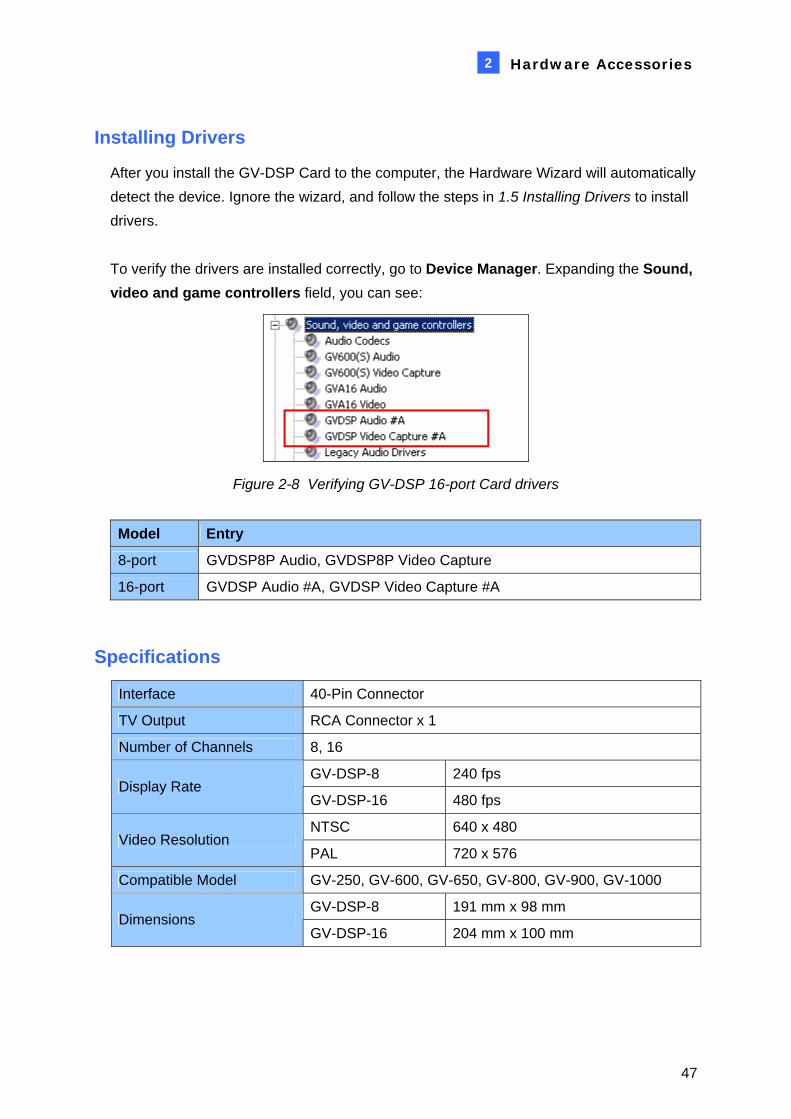
Installing Drivers
After you install the GV-DSP Card to the computer, the Hardware Wizard will automatically detect the device. Ignore the wizard, and follow the steps in 1.5 Installing Drivers to install drivers. To verify the drivers are installed correctly, go to Device Manager. Expanding the Sound, video and game controllers field, you can see:
Figure 2-8 Verifying GV-DSP 16-port Card drivers
Model Entry
8-port GVDSP8P Audio, GVDSP8P Video Capture
16-port GVDSP Audio #A, GVDSP Video Capture #A
Specifications
Interface 40-Pin Connector
TV Output RCA Connector x 1
Number of Channels 8, 16
GV-DSP-8 240 fps Display Rate
GV-DSP-16 480 fps
NTSC 640 x 480 Video Resolution
PAL 720 x 576
Compatible Model GV-250, GV-600, GV-650, GV-800, GV-900, GV-1000
GV-DSP-8 191 mm x 98 mm Dimensions
GV-DSP-16 204 mm x 100 mm
47

2.5 GV-A16 Card The GV-A16 Card can work with the GV-Video Capture Card to record audio for 16 channels, and to provide full duplex audio communication between local and remote users.
Packing List
1. GV-A16 Card x 1
2. 1-8 D-Type Audio Cable x 1
3. 9-16 D-Type Audio Cable x 1
4. Installation Guide x 1
Connections
Connect the audio cables to the GV-A16 Card as illustrated below.
GV-A16 Card1
3 9-16 D-Type Audio Cable
2 1-8 D-Type Audio Cable
Figure 2-9 GV-A16 Card Connections
48

Hardware Accessories 2
Installing Drivers
After you install the GV-A16 Card to the computer, the Hardware Wizard will automatically detect the device. Ignore the wizard, and follow the steps in 1.5 Installing Drivers, Chapter 1 to install drivers. To verify the drivers are installed correctly, go to Device Manager. Expanding the Sound, video and game controllers field, you should see the entries for GVA16 Audio and GVA16 Video.
Figure 2-10 Verifying GV-A16 Card drivers
Specifications
Interface DB9 Connector x 2
Number of Channels 16
Audio Compression ADPCM 8 bit Mono
Compatible Model GV-600, GV-650, GV-800, GV-900, GV-1000
Dimensions 120 mm x 91 mm
49

2.6 GV-NET Card V3.1 The GV-NET Card is a RS-485 / RS-232 interface converter. This Card connects to the RS-232 port or USB port on your computer, and allows RS-485 devices, such as PTZ domes, to be connected through the Card.
Packing List
1. GV-NET Card x 1
2. RJ-11 to DB9 Cable x 1
3. RJ-11 to USB Cable x 1
4. 3-Pin Internal USB Cable x 1
5. 4-Pin to 4-Pin Mini Power Cable x 1
6. Installation Guide x 1
Overview
RS-485 +RS-485 -
GV-NET Card
+-
ON
1
Connects to PC's COM port
or USB port
4-Pin to 4-PinMini Power Cable
5Connects to the USB Connectors on the PC 's motherboard
Figure 2-11 GV-Net Card V3.0 Connections
Note: The GV-NET Card only provides RS-485 / RS-232 data conversion; the
connection to the GV-Video Capture Card is not required.
50

Hardware Accessories 2
RS-485 Device Connections
To connect the GV-NET Card to the RS-485 devices, there are three ways of connections. See the pictures below.
1. You can connect a RJ-11 to DB9 Cable to the PC's COM Port when a RS-485 device is connected.
Connects to PC's COM PortRJ-11 to DB9 Cable2
PTZ DomeRS-485+
RS-485-
ON
Figure 2- 12
2. You can connect a RJ-11 to USB Cable to the PC's USB Port when a RS-485 device is connected.
RJ-11 to USB Cable3
RS-485+
RS-485-
ON
PTZ Dome
Connects to PC's USB Port
Figure 2-13
Note: It is required to install the USB driver. For details, see 2.23 Installing USB Driver.
51

3. You can connect a 3-Pin Internal USB Cable to the USB connectors on the PC's Motherboard when a RS-485 device is connected.
3-Pin Internal USB Cable
Connects to the USB Connectors on the PC'sMotherboard
DM (D-)
GND
(white)(green)(black)
DMDP
GND
(white)(green)(black)
RS-485+
RS-485-
ON
DP (D+)
PTZ Dome
4VCC
Figure 2-14
Note: It is required to install the USB driver. For details, see 2.23 Installing USB Driver.
Specifications
RJ-11 to DB9 (RS-232)
RJ-11 to USB
3-Pin Internal USB to Internal USB Interface
RS-485+ / RS-485-
Communication RS-485 1,200~115,200 bps; USB
Environmental Condition 0 to 50 Degree C, 5%-95% (Non-Condensing)
Compatible Model All GV-Video Capture Card Models
Dimensions 97 (W) x 90 (H) mm
52

Hardware Accessories 2
2.7 GV-NET/IO Card V3.1 The GV-NET/IO Card is a RS-485 / RS-232 interface converter, providing 4 inputs and 4
relay outputs as well. It supports both DC and AC output voltages.
Key Features
• A USB port is provided for PC connection, and it is used with 30 DC output voltages.
• It can switch between two modes, NET/IO Card Mode and I/O Box Mode, which expand its capability.
• Up to 4 GV-NET/IO Cards can be chained together when it is on the I/O Box Mode.
• It can act as an independent device when it is on the I/O Box Mode.
Packing List
1. GV-NET/IO Card x 1
2. RJ-11 to DB9 Cable x 1
3. RJ-11 to USB Cable x 1
4. 4-Pin to 4-Pin Mini Power Cable x 1
5. 3-Pin Internal USB Cable x 1
6. 20-Pin Ribbon Cable with 4 Connectors x1
7. Installation Guide x 1
53

Overview
GV Video Capture Card
RS-485 +RS-485 -
Relay Out 1Relay Out 2Relay Out 3Relay Out 4Com
Input 1Input 2Input 3Input 4Ground
4-Pin to 4-Pin MiniPower Cable
6
GV-NET I/O Card1
ON
20-PinRibbon Cable
2
1ON1 2
ON
1
ON
Figure 2-15 GV-NET/IO Card connections
Note:
1. The supplied RJ-11 to DB9 Cable of older versions is not compatible with the GV-NET/IO Card V3.1.
PC
Version 3.1With a PC Mark
Older VersionsWithout a PC Mark
2. When the GV-NET/IO Card V3.1 is in the I/O Box mode, it is incompatible with the GV-IO 12-In Card of versions earlier than V3.
3. To prevent the noise interference in I/O operation, tightly screw the GV-NET/IO Card to the PC case.
54
Hardware Accessories 2
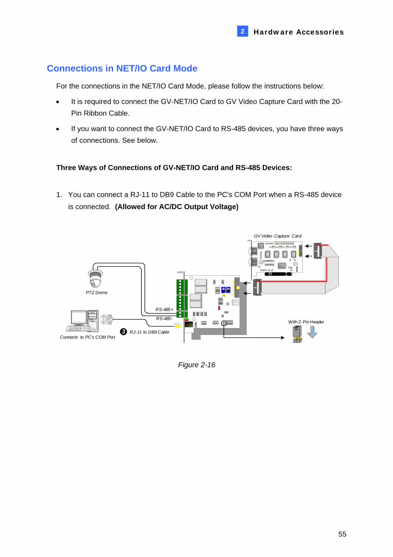
Connections in NET/IO Card Mode
For the connections in the NET/IO Card Mode, please follow the instructions below:
• It is required to connect the GV-NET/IO Card to GV Video Capture Card with the 20-Pin Ribbon Cable.
• If you want to connect the GV-NET/IO Card to RS-485 devices, you have three ways of connections. See below.
Three Ways of Connections of GV-NET/IO Card and RS-485 Devices:
1. You can connect a RJ-11 to DB9 Cable to the PC's COM Port when a RS-485 device is connected. (Allowed for AC/DC Output Voltage)
Connects to PC's COM PortRJ-11 to DB9 Cable3
1ON1 2
ON
1
ON
With 2-Pin Header
GV Video Capture Card
PTZ Dome
RS-485+
RS-485-
Figure 2-16
55

2. You can connect a RJ-11 to USB Cable to the PC's USB Port when a RS-485 device is connected. (Allowed for AC/DC Output Voltage)
RJ-11 to USB Cable4Connects to PC's USB Port
1ON1 2
ON
1
ON
With 2-Pin Header
PTZ Dome
RS-485+
RS-485-
GV Video Capture Card
Figure 2-17
Note: It is required to install the USB driver. For details, see 2.23 Installing USB Driver.
3. You can connect a 3-Pin Internal USB Cable to the USB Connectors on the PC's Motherboard when a RS-485 device is connected. (Allowed for AC/DC Output Voltage)
3-Pin Internal USB Cable
Connects to the USB Connectors on the PC 'smotherboard
DMDP
GND
(white)(green)(black)
1ON1 2
ON
1
ON
With 2-Pin Header
PTZ Dome
RS-485+
RS-485-
GV Video Capture Card
5
VCC
DM (D-)DP (D+)
GND
(white)
(green)(black)
Figure 2-18
Note: It is required to install the USB driver. For details, see 2.23 Installing USB Driver.
56

Hardware Accessories 2
Connections In I/O Box Mode
For the connections in the I/O Box Mode, please follow the instructions below:
• It is not necessary to connect the GV-NET/IO Card to GV Video Capture Card.
• Connect the GV-NET/IO Card to the PC by one of the following three ways.
Three Ways of Connections of GV-NET/IO Card and PC:
1. You can connect a RJ-11 to DB9 Cable to the PC's COM Port. (Allowed for AC/DC Output Voltage)
Chaining together with GV-NET/IO Box V 3.1 /
GV-IO USB Box
1ON1 2
ON
1
ON
Without 2-Pin Header
GV Video Capture Card
RS-485+
RS-485-
RJ-11 to DB9 Cable3
Figure 2-19
57

2. You can connect a RJ-11 to USB Cable to the PC's USB Port. (Allowed for DC Output Voltage only)
Chaining together with GV-NET/IO Box V 3.1 /
GV-IO USB Box
1ON1 2
ON
1
ON
GV Video Capture Card
RS-485+
RS-485-
RJ-11 to USB Cable4
Without 2-Pin Header
Figure 2-20
Note: It is required to install the USB driver. For details, see 2.23 Installing USB Driver.
3. You can connect a 3-Pin Internal USB Cable to the USB Connectors on the PC's
Motherboard. (Allowed for DC Output Voltage only)
1ON1 2
ON
1
ON
GV Video Capture Card
3-Pin Internal USB Cable
VCC
DMDP
GND
(white)(green)(black)
RS-485+
RS-485-
Chaining together with GV-NET/IO Box V 3.1 /
GV-IO USB Box
Without 2-Pin Header
Connects to the USB Connectors on the PC 's motherboard
5DM (D-)DP (D+)
GND
(white)
(green)(black)
Figure 2-21
Note: It is required to install the USB driver. For details, see 2.23 Installing USB Driver.
58

Hardware Accessories 2
Switching Modes
The GV-NET/IO Card provides two modes for users to expand its capability: I/O Box Mode and NET/IO Card Mode. With a mode-switch jumper to insert on the 2-pin header, you can switch between modes.
• NET/IO Card Mode (default): With the switch jumper inserted, this default mode acts as a GV-NET/IO Card. It is required to connect the GV-NET/IO Card to the GV Video Capture Card for usage.
• I/O Box Mode: Without the switch jumper inserted, the GV-NET/IO Card can work as an independent device. It is NOT necessary to connect to the GV Video Capture Card for usage.
2-Pin Header
1ON1 2
ON
1
ON
Figure 2-22
59

Extended Connections
Via the RS-485 connectors, up to 4 GV-NET/IO Cards can be chained together when the GV-NET/IO Card is on the I/O Box mode. For extended connections, the address assignment is shown below.
1 2
ON
1 2
ON
OFF/OFFAddress 1
1 2
ON
OFF/ONAddress 2
ON/OFF
1 2
ON
ON/ON
Address 3
Address 4(default)
Address AssignmentAddress Switch
1ON1 2
ON
1
ON
Figure 2-23
Note: When the GV-NET/IO Card is set to the I/O Box Mode, it can have extended
connections with GV-I/O Boxes.
DIP Switch
1ON1 2
ON
1
ON
OFF
WetContact
ON
DryContact (default)
1
ON
1
ON
Figure 2-24
60

Hardware Accessories 2
Specifications
Input 4 Input
Input Signal 9~30V AC/DC
Relay Output 4
Relay Status Normal Open
USB Connection 30V DC, 3A Output
Relay CapacitanceRS-232 Connection 125 / 250V AC, 3A
30V DC, 3A
RJ-11 to DB9
RJ-11 to USB Interface
3-Pin Internal USB to Internal USB
I/O Box Mode Without GV-Video Capture Card Mode Switch
NET/IO Card Mode With GV-Video Capture Card
Address 1~4
Communication RS-485, USB, RS-232
Environmental Condition 0-50 Degree C, 5%-95% (Non-Condensing)
Compatible Model All GV-Video Capture Card Models
Dimensions 99 mm x 90 mm
61
2.8 GV-IO 12-In Card V3 The GV-IO 12-In Card is designed to work with the GV-NET/IO Card. With 12 digital inputs, the GV-IO 12-In Card can expand the GV-System’s capacity up to 16 digital inputs.
System Requirements
• GV-NET/IO Card
Packing List
1. GV-IO 12-In Card x 1
2. 20-Pin Ribbon Cable with 4 connectors x 1
3. 4-Pin to 4-Pin Mini Power Cable x 1
4. Installation Guide x 1
62
Hardware Accessories
2
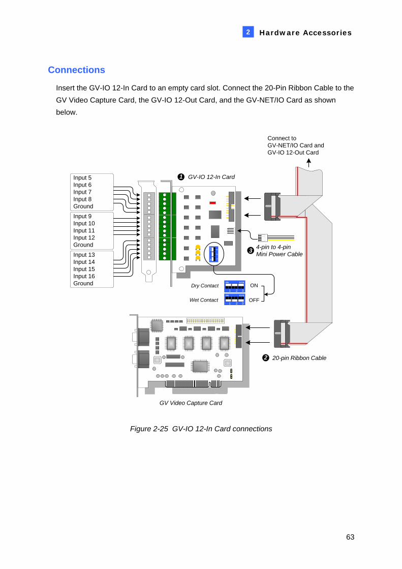
Connections
Insert the GV-IO 12-In Card to an empty card slot. Connect the 20-Pin Ribbon Cable to the GV Video Capture Card, the GV-IO 12-Out Card, and the GV-NET/IO Card as shown below.
12
EC
E
3
ON
GV Video Capture Card
Input 5Input 6Input 7Input 8Ground
OFFWet Contact
ON
GV-IO 12-In Card1
1 2
ECE
3
ON
1 2
ECE
3
ON
Dry Contact
20-pin Ribbon Cable2
Connect toGV-NET/IO Card and GV-IO 12-Out Card
Input 13Input 14Input 15Input 16Ground
Input 9Input 10Input 11Input 12Ground 4-pin to 4-pin
Mini Power Cable3
Figure 2-25 GV-IO 12-In Card connections
63
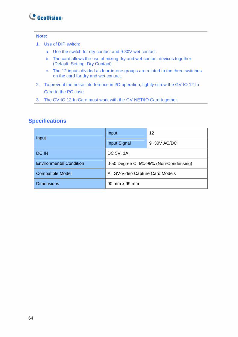
Note:
1. Use of DIP switch:
a. Use the switch for dry contact and 9-30V wet contact. b. The card allows the use of mixing dry and wet contact devices together.
(Default Setting: Dry Contact) c. The 12 inputs divided as four-in-one groups are related to the three switches
on the card for dry and wet contact.
2. To prevent the noise interference in I/O operation, tightly screw the GV-IO 12-In Card to the PC case.
3. The GV-IO 12-In Card must work with the GV-NET/IO Card together.
Specifications
Input 12 Input
Input Signal 9~30V AC/DC
DC IN DC 5V, 1A
Environmental Condition 0-50 Degree C, 5%-95% (Non-Condensing)
Compatible Model All GV-Video Capture Card Models
Dimensions 90 mm x 99 mm
64

Hardware Accessories
2
2.9 GV-IO 12-Out Card V3 The GV-IO 12-Out Card is designed to work with the GV-NET/IO Card. With 12 relay outputs, the GV-IO 12-out Card can expand the GV-System’s capacity up to 16 relay outputs.
System Requirements
• GV-NET/IO Card
Packing List
1. GV-IO 12-Out Card x 1
2. 20-Pin Ribbon Cable with 4 Connectors x 1
3. 4-Pin to 4-Pin Mini Power Cable x 1
4. Installation Guide x 1
65

Connections
Insert the GV-IO 12-Out Card to an empty card slot. Connect the 20-Pin Ribbon Cable to the GV Video Capture Card, the GV-IO 12-In Card, and the GV-NET/IO Card as shown below.
GV Video Capture Card
20-pin Ribbon Cable2
GV-IO 12-Out Card 1
Connect toGV-NET/IO Card and GV-IO 12-In Card
4-pin to 4-pinMini Power Cable3
Relay Out 5Relay Out 6Relay Out 7Relay Out 8Com
Relay Out 13Relay Out 14Relay Out 15Relay Out 16Com
Relay Out 9Relay Out 10Relay Out 11Relay Out 12Com
Figure 2-26 GV-IO 12-Out Card connections
Note:
1. To prevent noise interference in I/O operation, tightly screw the GV-IO 12-Out Card to the computer case.
2. The GV-IO 12-Out Card must work together with the GV-NET/IO Card.
66

Hardware Accessories
2
Specifications
Relay Output 12
Relay Status Normal Open
USB Connection 30V DC, 3A
Output
Relay Capacitance RS-232 Connection 125 / 250V AC, 3A
DC IN DC 5V, 1A
Environmental Condition 0~50 Degree C, 5%~95% (Non-Condensing)
Compatible Model All GV-Video Capture Card Models
Dimensions 120 mm x 99 mm
67

2.10 GV-NET Box The GV-NET Box is a RS-485 / RS-232 interface converter, the same function as the GV-NET Card. The differences are that the GV-NET Card is fixed within the computer and receives the power supply from your computer, while the GV-NET Box is an independent box and has its own power supply adaptor.
Packing List
1. GV-NET Box x 1
2. DB9 RS-232 Cable (1.8 meters) x 1
3. Power Adapter DC 5V x 1
4. Installation Guide x 1
Connections
• Use the supplied RS-232 cable to connect the GV-NET Box to the computer. • Use the power adaptor to connect the GV-NET Box to the power outlet.
RXD
TXD
PWR
RS-232 to PC RS-485+ -
DC IN
RS-232
Connects to power outlet
PC
GV-NET Box
Figure 2-27 GV-NET Box connections
RS-485 Device Connections
The connections of RS-485 devices to the GV-NET Box are the same as the GV-NET Card. Refer to the diagrams in RS-485 Device Connections, 2.6 GV-NET Card.
68

Hardware Accessories
2
Specifications
RS-232 to PC DB9 Male to DB9 Female Cable
RS-485 Interface Two Wires
Communication RS-485, 1,200-19,200 bps
DC IN Power Adapter DC 5V, IA Inner Positive
Environmental Condition 0 to 50 Degree C, 5%-95% (Non-Condensing)
Compatible Model All GV-Video Capture Card Models
Dimensions 103 (W) x 32 (H) x 64 (D) mm
69

2.11 GV-I/O USB Box The GV-I/O USB Box provides 16 inputs and 16 relay outputs. It not only supports both DC and AC output voltages but also provides a USB port.
Key Features
• It is a combination of both GV-I/O Box and GV-Relay Box.
• 16 inputs and 16 outputs are provided. See Important Notice for details.
• A USB port is provided for PC connection, and it is used for 30 DC output voltage.
• Up to 9 GV-I/O USB Boxes can be chained together. See Important Notice for details.
Important Notice
• Running with the GV-System earlier than V8.2, the GV-I/O USB Box only supports 8 inputs and 16 outputs. Up to 9 GV-I/O USB Boxes can be chained together.
• Running with the GV-System V8.2 and later, the GV-I/O USB Box can support 16 inputs and 16 outputs. Up to 9 GV-I/O USB Boxes can be chained together.
Packing List
1. GV-I/O USB Box x 1
2. Terminal Resistor x 1
3. Power Adapter DC 12V x 1
4. USB Cable (Type A to Type B) x 1
5. Installation Guide x 1
70

Hardware Accessories
2
Overview
3
BE
Figure 2-28
71

Connections to PC
There are two ways to connect the GV-I/O USB Box to PC:
• Use the USB cable to connect to the PC, and
• Use the RS-485 connectors to connect to the PC through the option of GV-Hub, GV-COM, GV-NET Card or GV-NET/IO Card.
1. You can connect to PC with the USB cable. (Allowed for DC Output Voltage only)
GV-IO
H
Output Input
DC 12V
COM.HDO 16DO 15DO 14DO 13
G
COM.GDO 12DO 11DO 10DO 9
F
COM.FDO 8DO 7DO 6DO 5
E
COM.EDO 4DO 3DO 2DO 1
RS-485 RXRX-485 TX
COM.DDI 16DI 15DI 14DI 13
COM.CDI 12DI 11DI 10DI 9
B
COM.BDI 8DI 7DI 6DI 5
A
COM.ADI 4DI 3DI 2DI 1
USB RXUSB TX
Figure 2-29
Note: It is required to install the USB driver. For details, see 2.23 Installing USB Driver.
2. You can connect to PC with the RS-485 connectors. (Allowed for AC/DC Output Voltage)
GV-IO
H
Output Input
DC 12V
COM.HDO 16DO 15DO 14DO 13
G
COM.GDO 12DO 11DO 10DO 9
F
COM.FDO 8DO 7DO 6DO 5
E
COM.EDO 4DO 3DO 2DO 1
RS-485 RXRX-485 TX
COM.DDI 16DI 15DI 14DI 13
COM.CDI 12DI 11DI 10DI 9
B
COM.BDI 8DI 7DI 6DI 5
A
COM.ADI 4DI 3DI 2DI 1
USB RXUSB TX
Figure 2-30
72

Hardware Accessories
2
Assigning Addresses to GV-I/O USB Boxes
Up to 9 GV-I/O USB Boxes can be chained together to expand the I/O capacity. Use the ID Switch to assign addresses 1~ 9 to the connected GV-I/O USB Boxes.
GV-I/O USB Box1 GV-IO
H
Output Input
DC 12V
COM.HDO 16DO 15DO 14DO 13
G
COM.GDO 12DO 11DO 10DO 9
F
COM.FDO 8DO 7DO 6DO 5
E
COM.EDO 4DO 3DO 2DO 1
RS-485 RXRX-485 TX
COM.DDI 16DI 15DI 14DI 13
COM.CDI 12DI 11DI 10DI 9
B
COM.BDI 8DI 7DI 6DI 5
A
COM.ADI 4DI 3DI 2DI 1
USB RXUSB TX
GV-I/O USB Box 2 GV-IO
H
Output Input
DC 12V
COM.HDO 16DO 15DO 14DO 13
G
COM.GDO 12DO 11DO 10DO 9
F
COM.FDO 8DO 7DO 6DO 5
E
COM.EDO 4DO 3DO 2DO 1
RS-485 RXRX-485 TX
COM.DDI 16DI 15DI 14DI 13
COM.CDI 12DI 11DI 10DI 9
B
COM.BDI 8DI 7DI 6DI 5
A
COM.ADI 4DI 3DI 2DI 1
USB RXUSB TX
GV-I/O USB Box 9 GV-IO
H
Output Input
DC 12V
COM.HDO 16DO 15DO 14DO 13
G
COM.GDO 12DO 11DO 10DO 9
F
COM.FDO 8DO 7DO 6DO 5
E
COM.EDO 4DO 3DO 2DO 1
RS-485 RXRX-485 TX
COM.DDI 16DI 15DI 14DI 13
COM.CDI 12DI 11DI 10DI 9
B
COM.BDI 8DI 7DI 6DI 5
A
COM.ADI 4DI 3DI 2DI 1
USB RXUSB TX
PC
RXD
TXD
PWR
RS-232 to PC RS-485+ -
DC IN
GV-NET Box
RS-485-RS-485+
RS-485 +/-RS-485 +/-RS-485 +/-
Figure 2-31
Note: 1. Address 0 is NOT functional. 2. When the GV-I/O USB Box is connected with the GV-NET/IO Card:
• Assign Addresses 1 ~ 4 to the connected GV-NET/IO Cards.
• Assign Addresses 5 ~ 9 to the connected GV-I/O USB Boxes.
3. If you want to change the assigned address of the connected GV-I/O USB Box, set the switch to the new address, and then re-plug the power adaptor.
73

Long-Distance Connection
The supplied Terminal Resistor must be used when the connection distance is greater than 200 meters. When one GV-I/O USB Box is connected to another GV-I/O USB Box or more, only insert the Terminal Resistors in the RS-485 connectors of the first and the last connected GV-I/O USB Boxes.
Figure 2-32
When one GV-I/O USB Box is connected to one GV-NET/IO Card, only insert the Terminal Resistor in the GV-I/O USB Box.
Figure 2-33
74

Hardware Accessories
2
DIP Switch
The GV-I/O USB Box allows the use of mixing dry and wet contact devices together. The 16 inputs divided as four-in-one groups (A, B, C and D) are related to the 4 switches on the box for dry and wet contact. To change the inputs to different kind of contact, push the switch upward (wet contact) or downward (dry contact).
1 2 3 4ECEON
1 2 3 4ECEON
Figure 2-34
Specifications
GV-IO USB Box
Input 16 Input
Input Signal 9-30V AC/DC
Relay Output 16
Relay Status Normal Open
USB Connection 30V DC, 3A
Output
Relay Capacitance RS-485 Connection
125 / 250V AC, 3A30V DC, 3A
DC IN DC 12V, 1A
Address 1-15
Environmental Condition 0 to 50 Degree C, 5%-95% (Non-Condensing)
Dimensions 180 (W) x 27 (H) x 183 (D) mm
75

2.12 GV-Hub Box The GV-Hub adds four RS-232/RS-485 serial ports through your computer’s USB port. The plug and play USB solution for serial port extension is perfect for mobile instrumentation and POS applications.
Packing List
1. GV-Hub Box x 1
2. A to B USB Cable (1.2 meters) x 1
3. DB9 RS-232 Cable (1.8 meters) x 4
4. Installation CD x 1
5. Installation Guide x 1
Overview
Figure 2-35 GV-Hub
DIP Switches
To change the DIP switches, you must open the GV-Hub Box.
Default Setting 1 2 3 4
ECE
Standard Mode (TX Feedback)
1 2 3 4
ECE
Note: There are four sets of RS-232 / 485 ports (A-D). In a single set, you can only
choose RS-232 or RS-485 port for connection.
76

Hardware Accessories
2
Connections
Following provides two examples of using the GV-Hub:
Connecting POS Systems
The GV-Hub can provide a local connection for up to four POS systems, and deliver transaction data to the GV-System over a USB cable.
POS System 1
RS-232
GV-Data Capture 1
GV-Hub
GV-System
USBRS-232 orRS-485
RS-232
GV-Data Capture 4
POS System 4
Figure 2-36 Connecting POS systems
Connecting RS-485 Devices
With the GV-Hub, the GV-System can connect up to 16 PTZ domes and nine GV-IO and GV-Relay modules simultaneously.
Figure 2-37 Connecting RS-485 devices
77

Installing Drivers
When you connect the GV-Hub Box to the computer, the Found New Hardware Wizard will automatically detect the device. Ignore the wizard, and follow these steps to install the drivers. 1. Insert the installation CD to your computer. 2. Run GvUsb.exe. 3. When this warning window appears, click Continue Anyway. The drivers will be
installed automatically.
Figure 2-38 Hardware Installation
To verify the drivers are installed correctly, go to Device Manager. Expanding the Ports field, you should see the 4 entries for Prolific USB-to Serial Bridge.
Figure 2-39 Prolific USB-to Serial Bridge
78

Hardware Accessories
2
Specifications
Signal: DCD, RxD, TxD, DTR, GND, DSR, RTS, CTS
RS-232 Connecter: 4 x DB9 Male (A, B, C, D)
Signal: D+, D-, GND RS-485 Connector: 4 x Terminal Block
(A, B, C, D)
Serial Interface
Serial Line Protection 16 KV ESD for All Signals
USB 1.1, 1.0 Compliance
USB 2.0 Backward Compatible USB
Speed Full Speed 12 Mbps
Parity None, Even, Odd
Data Bit 7, 8
Stop Bit 1 (Default), 2
Flow Control RTS/CTS, XON/XOFF
Communication Parameters
Speed 600 bps to 115,200 bps
Environmental Conditions 0-55 Degree C, 5%-95% (Non-Condensing)
Dimensions 103 (W) x 30 (H) x 125 (D) mm
79
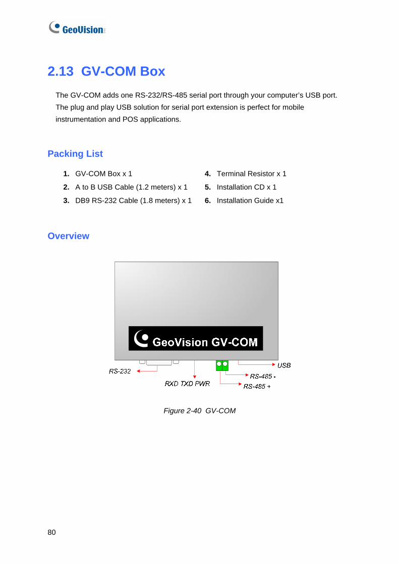
2.13 GV-COM Box The GV-COM adds one RS-232/RS-485 serial port through your computer’s USB port. The plug and play USB solution for serial port extension is perfect for mobile instrumentation and POS applications.
Packing List
1. GV-COM Box x 1
2. A to B USB Cable (1.2 meters) x 1
3. DB9 RS-232 Cable (1.8 meters) x 1
4. Terminal Resistor x 1
5. Installation CD x 1
6. Installation Guide x1
Overview
Figure 2-40 GV-COM
80

Hardware Accessories
2
Long-Distance Connection
When the two conditions below are met, the supplied Terminal Resistor needs to be used: 1. Conneciton distance is greater than 600 meters. 2. High-speed baud rate is applied, ex. 115200.
The diagram below illustrates how to use Terminal Resistor on Terminal Block attached to the RS-485 device:
Figure 2-41 Terminal Resistor connections
Installing Drivers
When you connect GV-COM to the computer, the Found New Hardware Wizard will automatically detect the device. To install the drive, follow the steps described in Installing Drivers, 2.12 GV-Hub Box. To verify the drivers are installed correctly, go to Device Manager. Expand the Ports field, and you should see one entry for Prolific USB-to-Serial Bridge.
Figure 2-42 Prolific USB-to-Serial Bridge
81

Specifications
Signal: DCD, RxD, TxD, DTR, GND, DSR, RTS, CTS RS-232 Connecter: DB9 Male
Signal: D+, D- RS-485
Connector: Terminal Block
Serial Interface
Serial Line Protection 16 KV ESD for All Signals
USB 1.1, 1.0 Compliance
USB 2.0 Backward Compatible USB
Speed Full speed 12 Mbps
Parity None, Even, Odd
Data Bit 7, 8
Stop Bit 1 (Default), 2
Flow Control RTS/CTS, XON/XOFF
Communication Parameters
Speed 600 bps to 115,200 bps
Environmental Conditions
0-55 Degree C, 5%-95% (Non-Condensing)
Dimensions 103 (W) x 32 (H) x 64 (D) mm
82

Hardware Accessories
2
2.14 GV-Data Capture V2 Box The GV-Data Catpure V2 can integrate your POS system (cash register) with the GV-System. Through the intergration, you can investigate a transaction with transaction data overlaying on video footage.
System Requirements
• GV-System Version 6.0.2.0 or above For details on GV-Data Capture V2 Box, see GV-Data Capture V2 User’s Manual attached with the product.
2.15 GV-Data Capture V2E Box The GV-Data Capture V2E is the network version of GV-Data Capture V2. With an Ethernet jack, the V2E allows you to integrate POS systems (cash registers) with the GV-System through LAN.
System Requirements
• GV-System Version 8.0 or above
For details on GV-Data Capture V2E Box, see GV-Data Capture V2E User’s Manual attached with the product.
83

2.16 GV-Data Capture V3 Series Compared to the V2E, the GV-Data Capture V3 Series, including V3 and V3E, not only provides LAN but Internet connection. In addition, the V3 Series can support both serial and parallel POS systems (cash registers).
System Requirements
• GV-Data Capture V3: GV-System version 6.0.2.0 or above • GV-Data Capture V3E: GV-System version 8.0.4.0 or above For details on GV-Data Capture V3 Series, see GV-Data Capture V3 Series User’s Manual attached with the product.
2.17 GV-Keyboard The GV-Keyboard is designed to program and operate GV-Systems. Through RS-485 configuration, it can control up to 16 additional GV-Systems.
System Requirements
• GV-System Version 7.0 or above
For details on GV-Keyboard, see GV-Keyboard Instruction Manual attached with the product.
84

Hardware Accessories
2
2.18 GV-Joystick The GV-Joystick facilitates the PTZ camera control such as pan, tilt, zoom and focus. It can work on the GV-System independently, and its compatibility with GV-Keyboard empowers the operation of GV-System as well.
System Requirements
• GV-System Version 8.2 or above
For details on GV-Joystick, see GV-Joystick User’s Manual attached with the product.
2.19 GV-IR Remote Control The GV-IR Remote Control is designed for basic system operation.
System Requirements
• GV-System Version 6.1 or above
For details on GV-IR Remote Control, see IR Remote Control User’s Manual attached with the product.
2.20 GV-Wiegand Capture Box The GV-Wiegand Capture can integrate your access control system with the GV-System. Through the integration, you can investigate the video footage overlaid with the cardholder’s name, ID, photo and related information.
System Requirements
• GV-System Version 8.1 or above
For details on GV-Wiegand Capture Box, see GV-Wiegand Capture User’s Manual attached with the product.
85

2.21 GV-Video Server The GV-Video Server can stream the real-time digital video over the Internet in the same way that current IP cameras do. With the GV-Video Server attached to analog cameras, you can see camera images through a web browser anywhere and anytime. With the GV-Video Server connected to the GV-System, your existing surveillance system can be upgraded and networked into a new IP surveillance system.
System Requirements
• GV-System Version 8.1 or above
For details on GV-Video Server, see GV-Video Server User’s Manual attached with the product.
2.22 GV-Compact DVR GV-Compact DVR is an all-in-one solution that makes monitoring more convenient. Its connection to Internet also makes the remote access possible.
System Requirements
• GV-System Version 8.2 or above
For details on GV-Compact DVR, see GV-Compact DVR User’s Manual attached with the product.
86

Hardware Accessories
87
2
2.23 Installing USB Driver To use the USB function, it is required to install the driver on the PC. Follow these steps to install the driver:
1. Insert the software CD. It will run automatically and pop up a window.
2. Select Install or Remove GeoVision GV-Series Driver, and then click Install GeoVision USB Devices Driver. This dialog box appears.
Figure 2-43
3. Click Install to install the drivers. When the installation is complete, this message will appear: Install done!
4. Click Exit to close the dialog box.
5. To verify the drivers are installed correctly, go to Device Manager. Expanding the Ports field, you should see one entry for Prolific USB-to-Serial Bridge.
Figure 2-44
Chapter 3 Software Installation
This chapter includes the following information:
• Important notice
• Installing a program
• Program list

3.1 Before You Start For optimal performance of your system, it is important to follow these recommendations before installing the system software:
• It is strongly recommended to divide your hard disk into two partitions. One partition is for installing Windows OS and System Software, and the other for storing audio/video files and system logs.
• When formatting hard disk, select NTFS as the file system on both logical drives.
• GV-System is a multi-channel video recording system. With normal use of the system, the logical drives containing video files will become fragmented. This is because GV-System constantly stores video files of multi channels simultaneously, and video files will be scattered all over the drives. It is not necessary to regularly perform disk defragmentation. Since the system software and video files are stored on two separated logical drives, the performance of your system will not be affected.
90

Software Installation 3
3.2 Installing the System When you insert the Surveillance System Software CD, the Install Program window will pop up automatically:
Figure 3-1 The Install Program Window
Before installing the system software, make sure DirectX 9.0c is already installed on your computer.
DirectX
If your computer doesn’t have the latest version of Direct X, click Install DirectX 9.0c in the Install Program window.
91

Installing the System
To install the GV-System, follow these steps:
1. In the Install Program window, click Install GeoVision xxx System (ex. Install GeoVision V8.2.0.0 System).
2. To install the Main System, select GeoVision Main System, and follow the on-screen instructions.
3. Follow the above steps to install other programs one by one.
Uninstalling the System
To uninstall the GV-System, follow these steps:
1. Close any open programs because your computer will restart during the uninstalling process.
2. On the taskbar, click Start, point to Programs, select the system folder, and then click Uninstall GeoVision System.
Note: Uninstalling the system will not delete video files and log files previously saved
in the computer.
92

Software Installation 3
3.3 Program List The Surveillance System Software CD includes the following programs: First Page:
1. Main System
2. Remote View
3. IP Multicast
4. Center V2
5. Fast Backup and Restore Multicam System
6. LocalDDNS Server
7. Authentication Server
8. Dynamic DNS Service
9. Remote Playback Client site
10. Microsoft PDA Viewer V2
Figure 3-2 First page of program installation
Second page:
11. Microsoft SmartPhone Viewer V2 (For Windows Mobile 5.0)
12. Microsoft SmartPhone Viewer V3 (For Windows Mobile 6.0)
13. Symbian SmartPhone Viewer V2
14. Symbian SmartPhone Viewer V3 (For Nokia S60 2nd and 3rd)
15. TwinDVR System
16. SMS Server
17. Software POS Driver (Only for Graphic mode POS system)
18. E-Map Server
19. MultiView
20. Remote EMap
Figure 3-3 Second page of program installation
93

94
Third page:
21. Remote ViewLog
22. Bandwidth Control Client Site
23. Backup Viewer
24. Single Player
Figure 3-4 Third page of program installation

Chapter 4 Screen Overview
The GV-System provides two skin types: Silver and Conventional. The factory default is Silver. Each skin type has its own interface design. Therefore, this chapter gives you an overview of the following major screens:
• Main System
• ViewLog
• Remote Playback Client
• SingleView MPEG4 Encoder Viewer
• MultiView MPEG4 Encoder Viewer
• Center V2
• Control Center

4.1 Main System Silver
Conventional
96

Screen Overview 4
The controls in the main screen:
No Name Description
1 Camera Number Indicates the camera number matching the port number in the GV video capture card.
2 Camera Name Indicates the given camera name.
3 Date/Time Indicates the current date and time.
4 Storage Space Indicates the remaining disk space.
5 Connection Indicates the connection status of remote applications.
6 PTZ Control Displays the PTZ control panel.
7 I/O Control Displays the I/O control panel.
8 TV-Out Displays the TV Quad control panel.
9 User-Defined Accesses other applications.
10 Location Name Indicates the GV-System’s name, usually named by its geographical location.
11 Network Enables the connection to remote applications
12 Camera Scan Rotates through the screen divisions.
13 ViewLog Brings up these options: Instant Play, Video/Audio Log, System Log, Search POS Data, POS Live View, Live Object Index, Search Object Index, Live Panorama View and E-Map.
14 Configure Accesses system settings.
15 Schedule Sets up recording schedules.
16 Monitor Starts or stops monitoring.
17 Camera Select Selects the desired camera number for main division view.
18 Screen Division Selects screen divisions.
19 Exit Brings up these options: Login/Change User, Logout, Minimize, Restart Multicam and Exit.
97

4.2 ViewLog Silver
Conventional
98

Screen Overview 4
The controls in the ViewLog window:
No Name Description
1 Camera Name Indicates the given camera name.
2 Camera View Displays the playback video.
3 Date Tree Displays date folders.
4 Video Event List Displays video events within a certain date folder.
5 Arrow Switch Switches between Event List and Connect Multi Host list.
6 View Mode Sets screen divisions: Single View, Panorama View, Quad View or Multi View. The Single View mode also includes these options: Standard, Thumbnail, Mega Pixel (PIP) and Mega Pixel (PAP).
7 Camera Select Sets a desired camera for display.
8 Advanced Accesses the basic, advanced search, timeline search and reloads video event list.
9 Normal Displays the date tree, video event list and multiple host connection list.
10 Function Panel Provides various settings for ViewLog.
11 Scroll Bar Scrolls forward or backward of the playback video.
12 Audio Playback Enables audio playback.
13 Playback Panel Contains typical playback control buttons.
14 Function Icons
A highlighted icon indicates an enabled function. From left to right are the A to B Mode, auto playing of next events, the contrast and brightness function, the light enhancement and equalization function, the sharpness and smoothness function, the grayscale function, and reconnection to Remote ViewLog.
15 Playback Speed Indicates the playback speed. x 1 represents normal playback speed.
16 Time Display Indicates the time of the playback video.
17 Date Display Indicates the date of the playback video.
18 Exit Closes or minimizes the ViewLog window.
19 A to B Mode Plays repeatedly the set frames A to B.
20 Frame by Frame / Real Time Plays back video frame by frame or on real time.
99

Silver Functional Panel
1
2
3
4
5
6
7
The controls in the Functional Panel:
No Name Description
1 Effects
Adds effects to the images. The effect options include: Sample, Contrast/Brightness, Light Enhancement, Equalization, Sharpen, Smooth, Defog, Stabilizer, Grayscale, Copy, Undo to Prev. Action and Undo All Effects.
2 Save As AVI Saves a video file as avi or exe format and displays the Merging List.
3 Save As Image Saves a video image as bmp, jpg, gif, png, or tif format.
4 Print Specifies various settings for printing.
5 Setting Accesses system settings of ViewLog.
6 Tools Brings up these options: Object Search, Advanced Log Browser, Delete Log, Remote ViewLog Service, Remote Backup Server, Address Book, Full Screen and Tool Kit.
7 Backup Backs up video files.
100

Screen Overview 4
Conventional Functional Panel
1
2
3
4
5
6
7
8
9
10
11
12
13
14
15
1616
The controls in the Function Panel:
No Name Description
1 Sample Gives the examples of “Before” and “After” effects of contrast, brightness, light enhancement, equalization, sharpness, smoothness and Gray.
2 Contrast/Brightness Modifies color contrast and brightness of the video image.
3 Light Enhancement/ Equalization
Modifies light enhancement and equalization of the video image. To remove the applied effect, click the Undo button.
4 Sharpen/Smooth Modifies smoothness and sharpness of the video image. To remove the applied effect, click the Undo button.
5 Grayscale Switches to the black/white image. To remove the applied effect, click the Undo button.
6 Advanced Video Analysis Enhances the video image using defogging or stabilizing effects.
7 Copy Copies the video image.
8 Undo Undoes the applied effects on the video image.
9 Save AVI File Saves a video file as avi or exe format and displays the Merging List.
10 Save As Image Saves a video image as bmp, jpg, gif , png, or tif format.
11 Print Prints out the image.
12 Print Setup Specifies various settings for printing.
13 Page Setup Adjusts the page layout.
14 Setting Accesses system settings of ViewLog.
15 Tools Brings up these options: Object Search, Advanced Log Browser, Delete Log, Remote ViewLog Service, Remote Backup Server, Address Book, Full Screen and Tool Kit.
16 Backup Backs up video files.
101

4.3 Remote Playback Client Silver
98
6
1110
12
43
5
7
15 14161713
1 2
Conventional
15 141617
3
4
5
6
7
8
9
10
11
12
13
21
102

Screen Overview 4
The controls in the RPB Client window:
No Name Description
1 Camera Name Indicates the given camera name.
2 Camera View Displays the playback video.
3 Connect Sets the connection to the RPB servers.
4 Disconnect Closes all or selected connections to the RPB servers.
5 Download (Play) Remote Video
Downloads and plays the remote video.
6 Play Local Video Plays back video files at the client computer.
7 View List Keeps track of connection activities.
8 Connection Record Keeps record of connection status.
9 Address Book Creates a quick connection to the RPB server.
10 Preference Setting Sets download status, text display and panel resolution.
11 Save As AVI Saves a video file as avi or exe format.
12 Save As BMP Saves a video image as bmp format.
13 Exit Closes or minimizes the RPB Client window.
14 Scroll Bar Moves forward and backward of the playback video.
15 Playback Panel Contains typical playback buttons.
16 Page Select Toggles between channels 1~16 and 17~32.
17 Screen Division Sets the screen divisions.
103

4.4 SingleView MPEG4 Encoder Viewer 1 2 4
8
101112
5
67
131415
16
9
3
The controls in the SingleView Viewer:
No Name Description
1 Countdown Timer Indicates the remaining time when you log in as Guest. When the time is up, you will be logged out automatically.
2 Menu Includes these options: Information, Video, Audio, Preset Go, I/O Control, Alarm Notify, Camera Adjustment and Download.
3 Expand / Close Expands or closes the Menu option list.
4 Option Selection Bar Selects the Menu option. For the list of options, see “Menu” above.
5 Show System Menu Brings up these options: Alarm Notify, Video and Audio Configuration, Remote Config, Change Server, Show Camera Name and Image Enhance.
6 Show Camera Menu Select the desired camera for display. 7 PTZ Control Displays the PTZ control panel. 8 I/O Control Displays the I/O control panel. 9 Full Screen Switches to full screen view.
10 File Save Saves live video in the local computer. Use the slide bar to adjust the time length of each saved clip.
11 Change Quality
Adjusts video quality with two options: Geo H264 and Geo MPEG4. If the connected site (GV-2004, GV-2008, GV-IP Camera, or GV-Video Server) supports hardware compression, the option of IP Camera MPEG2 or IP Camera MPEG4 appears.
12 Snapshot Takes a snapshot of the displayed live video. 13 Speaker Enables live audio from the remote GV-System. 14 Microphone Enables speaking to the remote GV-System. 15 Stop Terminates the connection to the remote GV-System. 16 Play Connects to the remote GV-System.
104

Screen Overview 4
4.5 MultiView MPEG4 Encoder Viewer
The controls in the MultiView Viewer:
No Name Description
1 Monitoring Window Displays live video.
2 Host Server Window Displays connected GV-Systems and their available cameras.
3 UPnP Device Displays all hosts on the same LAN.
4 PTZ Control Displays the PTZ control panel.
5 I/O Conrol Displays the I/O control panel.
6 Channel Status Indicates the general information of the selected channel.
7 ViewLog Accesses Remote ViewLog.
8 Configure Accesses system settings of the MultiView.
9 Edit Host Adds, deletes or modifies GV-Systems.
10 Camera Status Displays the camera status of the connected GV-Systems.
11 Host Information Displays the general information of the connected GV-Systems.
12 Zoom in and out Zooms in or out the selected channel.
105
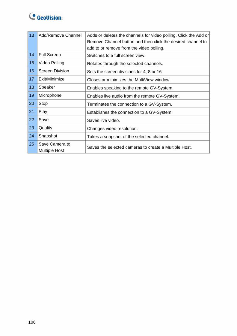
13 Add/Remove Channel Adds or deletes the channels for video polling. Click the Add or Remove Channel button and then click the desired channel to add to or remove from the video polling.
14 Full Screen Switches to a full screen view.
15 Video Polling Rotates through the selected channels.
16 Screen Division Sets the screen divisions for 4, 8 or 16.
17 Exit/Minimize Closes or minimizes the MultiView window.
18 Speaker Enables speaking to the remote GV-System.
19 Microphone Enables live audio from the remote GV-System.
20 Stop Terminates the connection to a GV-System.
21 Play Establishes the connection to a GV-System.
22 Save Saves live video.
23 Quality Changes video resolution.
24 Snapshot Takes a snapshot of the selected channel.
25 Save Camera to Multiple Host
Saves the selected cameras to create a Multiple Host.
106

Screen Overview 4
4.6 Remote Playback on WebCam
5 48 7 6
2
3
1
10 911121314
The controls in the Remote Playback on WebCam:
No Name Description
1 File Tree Displays date folders.
2 Event List Displays the video events
3 Channel Select Tab Selects different channels.
4 Option Includes the Enable DirectDraw option.
5 Object Search Searches Object Index.
6 Get Event List Displays the Event List.
7 Smart Search Includes the Advanced Search option.
8 Audio Enables live audio from the remote GV-System.
9 Pause Pauses the video file.
10 Play Plays the video file.
11 Stop Stops the video file.
12 Download Downloads the video file.
13 Snapshot Takes a snapshot of the displayed live video.
14 Full Screen Switches to a full screen view.
107

4.7 Center V2 Silver
17
1617
1820 21 22 23
2
3
4
567
1210
1113
1415
9
8
1
19
Conventional
1011
14
9
8
1
13
15
12
765
4
3
2
17
1617
1820 21 22 2319
108
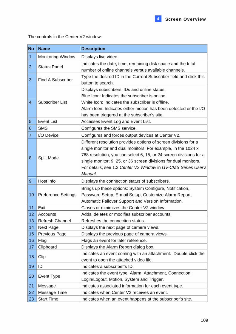
Screen Overview 4
The controls in the Center V2 window:
No Name Description
1 Monitoring Window Displays live video.
2 Status Panel Indicates the date, time, remaining disk space and the total number of online channels versus available channels.
3 Find A Subscriber Type the desired ID in the Current Subscriber field and click this button to search.
4 Subscriber List
Displays subscribers’ IDs and online status. Blue Icon: Indicates the subscriber is online. White Icon: Indicates the subscriber is offline. Alarm Icon: Indicates either motion has been detected or the I/O has been triggered at the subscriber’s site.
5 Event List Accesses Event Log and Event List. 6 SMS Configures the SMS service. 7 I/O Device Configures and forces output devices at Center V2.
8 Split Mode
Different resolution provides options of screen divisions for a single monitor and dual monitors. For example, in the 1024 x 768 resolution, you can select 6, 15, or 24 screen divisions for a single monitor; 9, 25, or 36 screen divisions for dual monitors. For details, see 1.3 Center V2 Window in GV-CMS Series User’s Manual.
9 Host Info Displays the connection status of subscribers.
10 Preference Settings Brings up these options: System Configure, Notification, Password Setup, E-mail Setup, Customize Alarm Report, Automatic Failover Support and Version Information.
11 Exit Closes or minimizes the Center V2 window. 12 Accounts Adds, deletes or modifies subscriber accounts. 13 Refresh Channel Refreshes the connection status. 14 Next Page Displays the next page of camera views. 15 Previous Page Displays the previous page of camera views. 16 Flag Flags an event for later reference. 17 Clipboard Displays the Alarm Report dialog box.
18 Clip Indicates an event coming with an attachment. Double-click the event to open the attached video file.
19 ID Indicates a subscriber’s ID.
20 Event Type Indicates the event type: Alarm, Attachment, Connection, Login/Logout, Motion, System and Trigger.
21 Message Indicates associated information for each event type. 22 Message Time Indicates when Center V2 receives an event. 23 Start Time Indicates when an event happens at the subscriber’s site.
109

110
4.8 Control Center Toolbar Silver
1 321 4 5
Conventional
1 321 4 5
The controls on the Control Center Toolbar:
No Name Description
1 Host List Opens the Host List to create and edit DVRs.
2 Group List Opens the Group List to group cameras from different DVRs.
3 IP Matrix List Opens the IP Matrix List to display up to 36 Matrix views.
4 Edit Opens the Edit toolbar to display these buttons: Search Host, Configure, Save, and Delete. The Add Host button only appears after the Host List is opened.
5 Service
Opens the Service toolbar to display these buttons: Remote Control, Remote ViewLog, VMD System, Remote E-Map and I/O Central Panel. The Matrix button only appears after the Group List is opened.

Troubleshooting
GV-System is designed to provide you with trouble-free performance. If it does not appear to be functioning correctly, please make sure all connectors are properly attached and follow these troubleshooting steps:
GV-System has video and/or audio lost.
If your GV-System fails to show video, audio or both, try these steps:
1. Check the video/audio connection.
2. Make sure the video/audio device is turned on.
3. Make sure the video standard in your country matches the setting in GV-System.
4. Switch the cable from the functional channel to the non-functional channel, and vice versa. If the previously non-functional channel is now able to deliver video/audio, you should check the video/audio device itself and its related cables.
The screen image appears distorted or jitters.
If the screen image seems to be distorted, jitter, or not to look right, try these steps:
1. Make sure the video standard in your country matches the setting in GV-System.
2. Make sure the camera and its cable are not damaged or frayed. Try to replace a camera or cable to see if this fixes the problem.
Messages “Can’t find keypro” and “Card Setup Fail” appear when
GV-System starts.
1. Verify the video capture card driver. See 1.6 Installing Drivers.
2. Insert the video capture card to a different PCI slot to see if this fixes the problem.
3. If you are using the video capture card V1, attach an appropriate Keypro to the PC’s parallel port and run Dos2kreg.exe from the GV-System folder.
4. If using GV-600, GV-650 or GV-650 and running the version between 7.0 and 7.0.5.0, you may need an appropriate USB dongle.
5. If running the version of 8.0 or later and using GV-250, GV-600 V4, GV-650 V4, GV-800 V4, GV-1120, GV-1240, GV-1480, GV-2004 or GV-2008, you may follow Steps 1 and 2 to fix the problem.
112
Troubleshooting
A message “Can’t find new xxx Module:1, Address:1, in Com1”
appears.
1. Check the RS-485 or USB connection between the GV-System and the GV I/O device.
2. Check whether the power adapter is properly attached to the GV I/O device.
3. Check whether the Port and Address settings on the I/O Devices tab in the System Configure dialog box are correct.
A message “No PTZ Device Installed” or “Default PTZ Device not
Activate” appears.
1. Make sure the Activate option is enabled in Main System. See Step 4, “PTZ Control Panel”, Chapter 1, User’s Manual on the Surveillance System Software CD.
2. If multiple PTZ cameras are installed, make sure to activate each PTZ camera individually.
How can I find more help?
1. Visit our website at http://www.geovision.com.tw/english/4_1.asp
2. Write us at [email protected]
113

114