
Installation Guide - usermanual.wiki · The installation process involves installing an RRU and RRU...
96
RRU3201 Installation Guide Issue 06 Date 2012-04-16 HUAWEI TECHNOLOGIES CO., LTD.
Transcript of Installation Guide - usermanual.wiki · The installation process involves installing an RRU and RRU...
RRU3201
Installation Guide
Issue 06
Date 2012-04-16
HUAWEI TECHNOLOGIES CO., LTD.
Copyright © Huawei Technologies Co., Ltd. 2012. All rights reserved.No part of this document may be reproduced or transmitted in any form or by any means without prior writtenconsent of Huawei Technologies Co., Ltd. Trademarks and Permissions
and other Huawei trademarks are trademarks of Huawei Technologies Co., Ltd.All other trademarks and trade names mentioned in this document are the property of their respective holders. NoticeThe purchased products, services and features are stipulated by the contract made between Huawei and thecustomer. All or part of the products, services and features described in this document may not be within thepurchase scope or the usage scope. Unless otherwise specified in the contract, all statements, information,and recommendations in this document are provided "AS IS" without warranties, guarantees or representationsof any kind, either express or implied.
The information in this document is subject to change without notice. Every effort has been made in thepreparation of this document to ensure accuracy of the contents, but all statements, information, andrecommendations in this document do not constitute the warranty of any kind, express or implied.
Huawei Technologies Co., Ltd.Address: Huawei Industrial Base
Bantian, LonggangShenzhen 518129People's Republic of China
Website: http://www.huawei.com
Email: [email protected]
Issue 06 (2012-04-16) Huawei Proprietary and ConfidentialCopyright © Huawei Technologies Co., Ltd.
i
About This Document
PurposeThis document describes the process of installing a DC RRU3201 (referred to as RRU in thisdocument).
Product VersionsThe following table lists the product versions related to this document.
Product Name Product Version
DBS3900 V100R004C00 and later versions
DBS3900 LTE V100R003C00 and later versions
Intended AudienceThis document is intended for:
Base station installation engineers
Organization1 Changes in the RRU3201 Installation Guide
This chapter describes the changes in the RRU3201 Installation Guide.
2 Installation Preparations
This chapter describes the reference documents, tools, and instruments that must be ready beforethe installation. In addition, it specifies the skills and prerequisites that installation engineersmust have.
3 Information About the Installation
Before installing an RRU, you must be familiar with its exterior, ports, installation options,physical supports, and installation clearance requirements.
4 Unpacking the Equipment
RRU3201Installation Guide About This Document
Issue 06 (2012-04-16) Huawei Proprietary and ConfidentialCopyright © Huawei Technologies Co., Ltd.
ii
This chapter describes how to unpack and check the delivered equipment to ensure that all thematerials are included and intact.
5 Installation Process
The installation process involves installing an RRU and RRU cables, checking the RRUhardware installation, and powering on the RRU.
6 Hoisting an RRU and Related Cables onto a Tower
This section describes the procedure for hoisting an RRU and related cables onto a tower andthe precautions that must be taken.
7 Installing the RRU
This chapter describes the procedure for installing the RRU. The RRU can be installed on a pole,U-steel, angle steel, or wall. The procedure for installing the RRU varies depending oninstallation options.
8 Installing RRU Cables
This chapter describes the procedure for installing RRU cables.
9 Checking the RRU Hardware Installation
After an RRU is installed, check the hardware installation.
10 Powering On an RRU
After all the devices are installed, check the power-on status of an RRU.
11 Appendix
This section describes the procedure for adding OT terminals.
ConventionsSymbol Conventions
The symbols that may be found in this document are defined as follows.
Symbol Description
Indicates a hazard with a high level of risk, which if notavoided, will result in death or serious injury.
Indicates a hazard with a medium or low level of risk, whichif not avoided, could result in minor or moderate injury.
Indicates a potentially hazardous situation, which if notavoided, could result in equipment damage, data loss,performance degradation, or unexpected results.
Indicates a tip that may help you solve a problem or savetime.
Provides additional information to emphasize or supplementimportant points of the main text.
RRU3201Installation Guide About This Document
Issue 06 (2012-04-16) Huawei Proprietary and ConfidentialCopyright © Huawei Technologies Co., Ltd.
iii
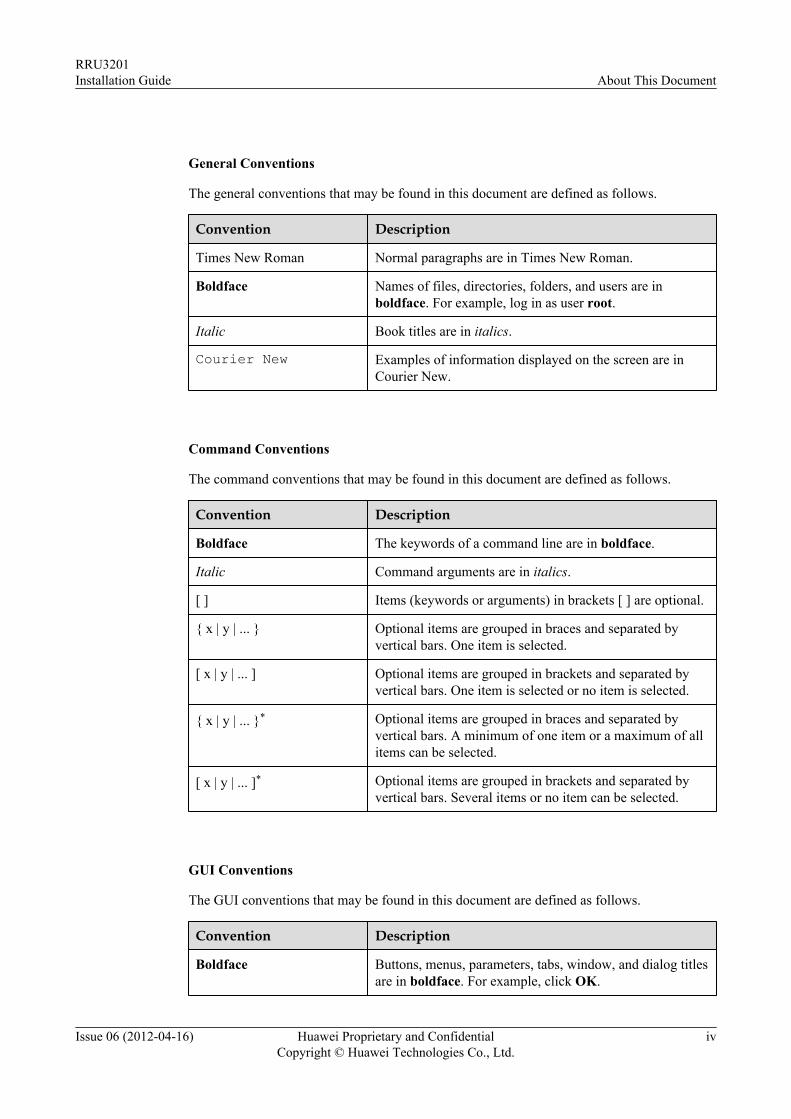
General Conventions
The general conventions that may be found in this document are defined as follows.
Convention Description
Times New Roman Normal paragraphs are in Times New Roman.
Boldface Names of files, directories, folders, and users are inboldface. For example, log in as user root.
Italic Book titles are in italics.
Courier New Examples of information displayed on the screen are inCourier New.
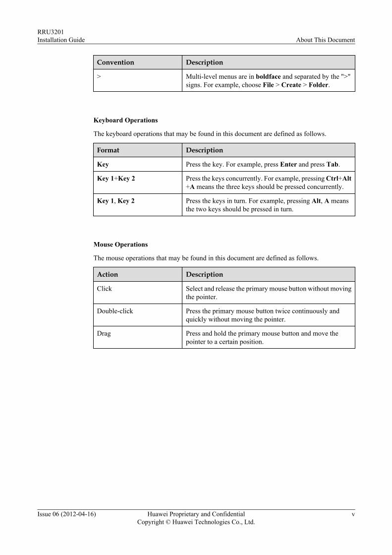
Command Conventions
The command conventions that may be found in this document are defined as follows.
Convention Description
Boldface The keywords of a command line are in boldface.
Italic Command arguments are in italics.
[ ] Items (keywords or arguments) in brackets [ ] are optional.
{ x | y | ... } Optional items are grouped in braces and separated byvertical bars. One item is selected.
[ x | y | ... ] Optional items are grouped in brackets and separated byvertical bars. One item is selected or no item is selected.
{ x | y | ... }* Optional items are grouped in braces and separated byvertical bars. A minimum of one item or a maximum of allitems can be selected.
[ x | y | ... ]* Optional items are grouped in brackets and separated byvertical bars. Several items or no item can be selected.
GUI Conventions
The GUI conventions that may be found in this document are defined as follows.
Convention Description
Boldface Buttons, menus, parameters, tabs, window, and dialog titlesare in boldface. For example, click OK.
RRU3201Installation Guide About This Document
Issue 06 (2012-04-16) Huawei Proprietary and ConfidentialCopyright © Huawei Technologies Co., Ltd.
iv
Convention Description
> Multi-level menus are in boldface and separated by the ">"signs. For example, choose File > Create > Folder.
Keyboard Operations
The keyboard operations that may be found in this document are defined as follows.
Format Description
Key Press the key. For example, press Enter and press Tab.
Key 1+Key 2 Press the keys concurrently. For example, pressing Ctrl+Alt+A means the three keys should be pressed concurrently.
Key 1, Key 2 Press the keys in turn. For example, pressing Alt, A meansthe two keys should be pressed in turn.
Mouse Operations
The mouse operations that may be found in this document are defined as follows.
Action Description
Click Select and release the primary mouse button without movingthe pointer.
Double-click Press the primary mouse button twice continuously andquickly without moving the pointer.
Drag Press and hold the primary mouse button and move thepointer to a certain position.
RRU3201Installation Guide About This Document
Issue 06 (2012-04-16) Huawei Proprietary and ConfidentialCopyright © Huawei Technologies Co., Ltd.
v
Contents
About This Document.....................................................................................................................ii
1 Changes in the RRU3201 Installation Guide...........................................................................1
2 Installation Preparations..............................................................................................................42.1 Reference Documents.........................................................................................................................................52.2 Tools and Instruments........................................................................................................................................52.3 Skills and Requirements for Onsite Personnel...................................................................................................6
3 Information About the Installation...........................................................................................73.1 RRU Exterior......................................................................................................................................................83.2 RRU Ports...........................................................................................................................................................93.3 RRU Indicators.................................................................................................................................................103.4 Installation Options...........................................................................................................................................123.5 Installation Clearance Requirements of an RRU..............................................................................................16
3.5.1 Installation Clearance for a Single RRU.................................................................................................173.5.2 Installation Clearance for Multiple RRUs...............................................................................................183.5.3 Installation Spacing Between RRUs........................................................................................................21
4 Unpacking the Equipment.........................................................................................................25
5 Installation Process.....................................................................................................................27
6 Hoisting an RRU and Related Cables onto a Tower............................................................286.1 Hoisting an RRU onto a Tower........................................................................................................................296.2 Hoisting Fiber Optic Cables onto a Tower.......................................................................................................326.3 Hoisting Power Cables onto a Tower...............................................................................................................35
7 Installing the RRU.......................................................................................................................377.1 Mounting Kits for an RRU...............................................................................................................................387.2 Installing the RRU on a Pole............................................................................................................................38
7.2.1 Installing a Single RRU...........................................................................................................................417.2.2 Installing Two RRUs...............................................................................................................................437.2.3 Installing Multiple RRUs.........................................................................................................................46
7.3 Installing the RRU on U-steel..........................................................................................................................497.4 Installing the RRU on Angle Steel...................................................................................................................537.5 Installing the RRU on a Wall...........................................................................................................................56
RRU3201Installation Guide Contents
Issue 06 (2012-04-16) Huawei Proprietary and ConfidentialCopyright © Huawei Technologies Co., Ltd.
vi
8 Installing RRU Cables................................................................................................................618.1 Cabling Requirements......................................................................................................................................628.2 Cable Connections............................................................................................................................................678.3 Installation Process...........................................................................................................................................688.4 RRU Cable List................................................................................................................................................698.5 Installing an RRU PGND Cable.......................................................................................................................708.6 Installing an RRU RF Jumper..........................................................................................................................718.7 Installing an RRU AISG Multi-Wire Cable and AISG Extension Cable.........................................................748.8 Opening the Cover Plate of an RRU Cabling Cavity.......................................................................................768.9 Installing an RRU power cable.........................................................................................................................788.10 Installing a CPRI Fiber Optic Cable...............................................................................................................808.11 Closing the Cover Plate of an RRU Cabling Cavity......................................................................................82
9 Checking the RRU Hardware Installation..............................................................................84
10 Powering On an RRU...............................................................................................................85
11 Appendix.....................................................................................................................................8611.1 Adding OT Terminals to the RRU Power Cable on the RRU Side................................................................87
RRU3201Installation Guide Contents
Issue 06 (2012-04-16) Huawei Proprietary and ConfidentialCopyright © Huawei Technologies Co., Ltd.
vii
1 Changes in the RRU3201 Installation Guide
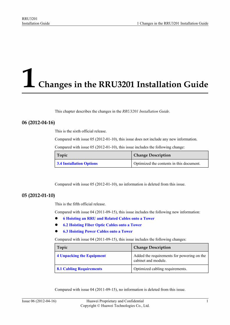
This chapter describes the changes in the RRU3201 Installation Guide.
06 (2012-04-16)This is the sixth official release.
Compared with issue 05 (2012-01-10), this issue does not include any new information.
Compared with issue 05 (2012-01-10), this issue includes the following change:
Topic Change Description
3.4 Installation Options Optimized the contents in this document.
Compared with issue 05 (2012-01-10), no information is deleted from this issue.
05 (2012-01-10)This is the fifth official release.
Compared with issue 04 (2011-09-15), this issue includes the following new information:l 6 Hoisting an RRU and Related Cables onto a Towerl 6.2 Hoisting Fiber Optic Cables onto a Towerl 6.3 Hoisting Power Cables onto a Tower
Compared with issue 04 (2011-09-15), this issue includes the following changes:
Topic Change Description
4 Unpacking the Equipment Added the requirements for powering on thecabinet and module.
8.1 Cabling Requirements Optimized cabling requirements.
Compared with issue 04 (2011-09-15), no information is deleted from this issue.
RRU3201Installation Guide 1 Changes in the RRU3201 Installation Guide
Issue 06 (2012-04-16) Huawei Proprietary and ConfidentialCopyright © Huawei Technologies Co., Ltd.
1
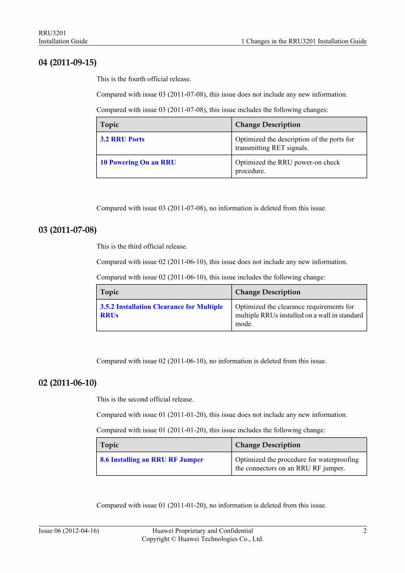
04 (2011-09-15)
This is the fourth official release.
Compared with issue 03 (2011-07-08), this issue does not include any new information.
Compared with issue 03 (2011-07-08), this issue includes the following changes:
Topic Change Description
3.2 RRU Ports Optimized the description of the ports fortransmitting RET signals.
10 Powering On an RRU Optimized the RRU power-on checkprocedure.
Compared with issue 03 (2011-07-08), no information is deleted from this issue.
03 (2011-07-08)
This is the third official release.
Compared with issue 02 (2011-06-10), this issue does not include any new information.
Compared with issue 02 (2011-06-10), this issue includes the following change:
Topic Change Description
3.5.2 Installation Clearance for MultipleRRUs
Optimized the clearance requirements formultiple RRUs installed on a wall in standardmode.
Compared with issue 02 (2011-06-10), no information is deleted from this issue.
02 (2011-06-10)
This is the second official release.
Compared with issue 01 (2011-01-20), this issue does not include any new information.
Compared with issue 01 (2011-01-20), this issue includes the following change:
Topic Change Description
8.6 Installing an RRU RF Jumper Optimized the procedure for waterproofingthe connectors on an RRU RF jumper.
Compared with issue 01 (2011-01-20), no information is deleted from this issue.
RRU3201Installation Guide 1 Changes in the RRU3201 Installation Guide
Issue 06 (2012-04-16) Huawei Proprietary and ConfidentialCopyright © Huawei Technologies Co., Ltd.
2
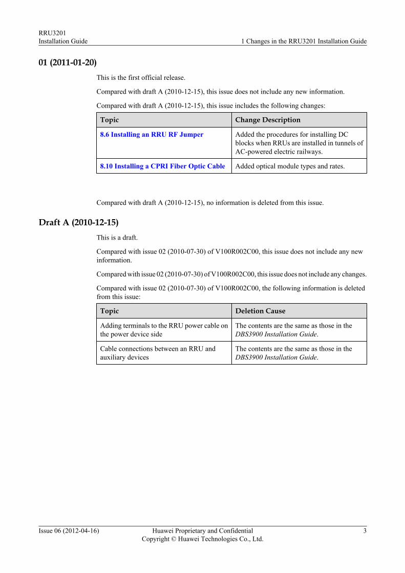
01 (2011-01-20)This is the first official release.
Compared with draft A (2010-12-15), this issue does not include any new information.
Compared with draft A (2010-12-15), this issue includes the following changes:
Topic Change Description
8.6 Installing an RRU RF Jumper Added the procedures for installing DCblocks when RRUs are installed in tunnels ofAC-powered electric railways.
8.10 Installing a CPRI Fiber Optic Cable Added optical module types and rates.
Compared with draft A (2010-12-15), no information is deleted from this issue.
Draft A (2010-12-15)This is a draft.
Compared with issue 02 (2010-07-30) of V100R002C00, this issue does not include any newinformation.
Compared with issue 02 (2010-07-30) of V100R002C00, this issue does not include any changes.
Compared with issue 02 (2010-07-30) of V100R002C00, the following information is deletedfrom this issue:
Topic Deletion Cause
Adding terminals to the RRU power cable onthe power device side
The contents are the same as those in theDBS3900 Installation Guide.
Cable connections between an RRU andauxiliary devices
The contents are the same as those in theDBS3900 Installation Guide.
RRU3201Installation Guide 1 Changes in the RRU3201 Installation Guide
Issue 06 (2012-04-16) Huawei Proprietary and ConfidentialCopyright © Huawei Technologies Co., Ltd.
3
2 Installation Preparations
About This Chapter
This chapter describes the reference documents, tools, and instruments that must be ready beforethe installation. In addition, it specifies the skills and prerequisites that installation engineersmust have.
2.1 Reference DocumentsBefore the installation, you must be familiar with reference documents.
2.2 Tools and InstrumentsAll tools and instruments required for RRU installation must be ready before the installation.
2.3 Skills and Requirements for Onsite PersonnelOnsite personnel must be qualified and trained. Before performing any operation, onsitepersonnel must be familiar with correct operation methods and safety precautions.
RRU3201Installation Guide 2 Installation Preparations
Issue 06 (2012-04-16) Huawei Proprietary and ConfidentialCopyright © Huawei Technologies Co., Ltd.
4
2.1 Reference DocumentsBefore the installation, you must be familiar with reference documents.
The following reference documents are required during RRU installation:l RRU3201 Hardware Descriptionl DBS3900 Installation Guidel OCB User Guide
This document describes the RRU installation on a pole, U-steel, angle steel, or wall. If RRUsare installed on the IFS06, the following reference document is required:l DBS3900 (ICR) Installation Guide
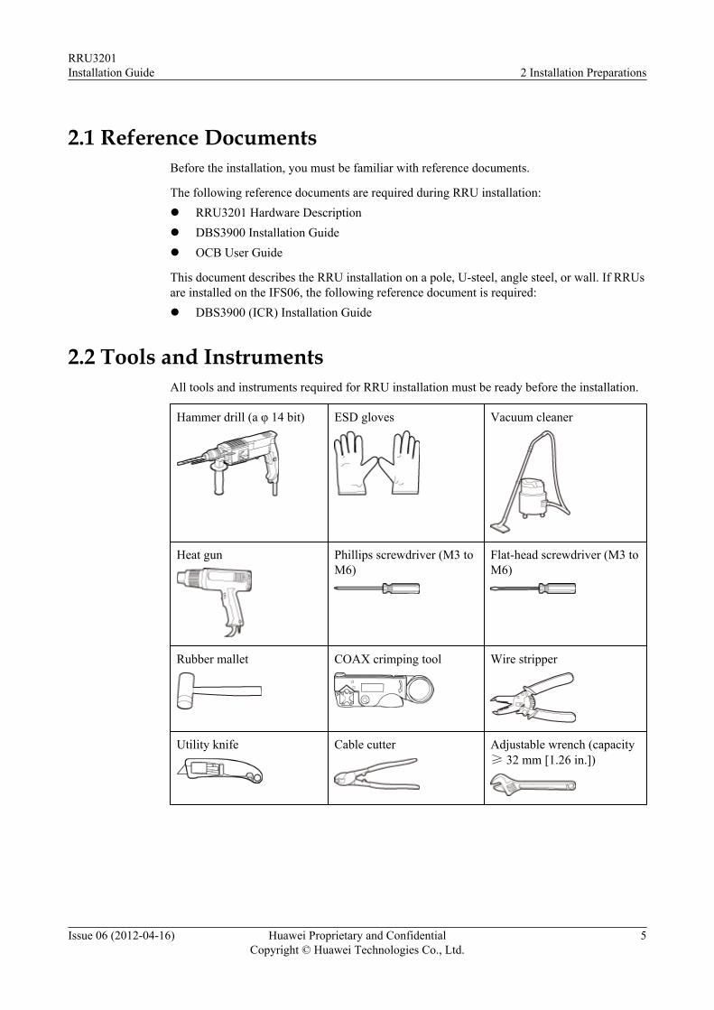
2.2 Tools and InstrumentsAll tools and instruments required for RRU installation must be ready before the installation.
Hammer drill (a φ 14 bit) ESD gloves Vacuum cleaner
Heat gun Phillips screwdriver (M3 toM6)
Flat-head screwdriver (M3 toM6)
Rubber mallet COAX crimping tool Wire stripper
Utility knife Cable cutter Adjustable wrench (capacity≥ 32 mm [1.26 in.])
RRU3201Installation Guide 2 Installation Preparations
Issue 06 (2012-04-16) Huawei Proprietary and ConfidentialCopyright © Huawei Technologies Co., Ltd.
5
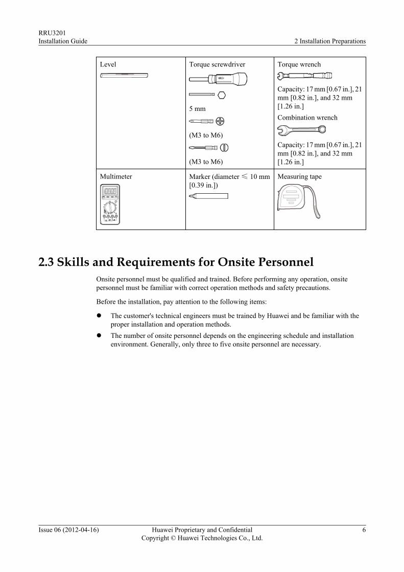
Level Torque screwdriver
5 mm
(M3 to M6)
(M3 to M6)
Torque wrench
Capacity: 17 mm [0.67 in.], 21mm [0.82 in.], and 32 mm[1.26 in.]Combination wrench
Capacity: 17 mm [0.67 in.], 21mm [0.82 in.], and 32 mm[1.26 in.]
Multimeter Marker (diameter ≤ 10 mm[0.39 in.])
Measuring tape
2.3 Skills and Requirements for Onsite PersonnelOnsite personnel must be qualified and trained. Before performing any operation, onsitepersonnel must be familiar with correct operation methods and safety precautions.
Before the installation, pay attention to the following items:
l The customer's technical engineers must be trained by Huawei and be familiar with theproper installation and operation methods.
l The number of onsite personnel depends on the engineering schedule and installationenvironment. Generally, only three to five onsite personnel are necessary.
RRU3201Installation Guide 2 Installation Preparations
Issue 06 (2012-04-16) Huawei Proprietary and ConfidentialCopyright © Huawei Technologies Co., Ltd.
6
3 Information About the Installation
About This Chapter
Before installing an RRU, you must be familiar with its exterior, ports, installation options,physical supports, and installation clearance requirements.
3.1 RRU ExteriorThis section describes the exterior and dimensions of an RRU.
3.2 RRU PortsThis section describes RRU ports positioned on the RRU panels. An RRU has a bottom panel,cabling cavity panel, and indicator panel.
3.3 RRU IndicatorsThis section describes six indicators on an RRU. They indicate the running status.
3.4 Installation OptionsThis section describes RRU installation options. An RRU can be installed on a pole, U-steel,angle steel, or wall.
3.5 Installation Clearance Requirements of an RRUThis section describes the requirements for the installation clearance of a single RRU andmultiple RRUs and the requirements for the installation spacing between RRUs.
RRU3201Installation Guide 3 Information About the Installation
Issue 06 (2012-04-16) Huawei Proprietary and ConfidentialCopyright © Huawei Technologies Co., Ltd.
7
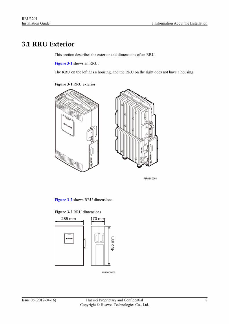
3.1 RRU ExteriorThis section describes the exterior and dimensions of an RRU.
Figure 3-1 shows an RRU.
The RRU on the left has a housing, and the RRU on the right does not have a housing.
Figure 3-1 RRU exterior
Figure 3-2 shows RRU dimensions.
Figure 3-2 RRU dimensions
RRU3201Installation Guide 3 Information About the Installation
Issue 06 (2012-04-16) Huawei Proprietary and ConfidentialCopyright © Huawei Technologies Co., Ltd.
8
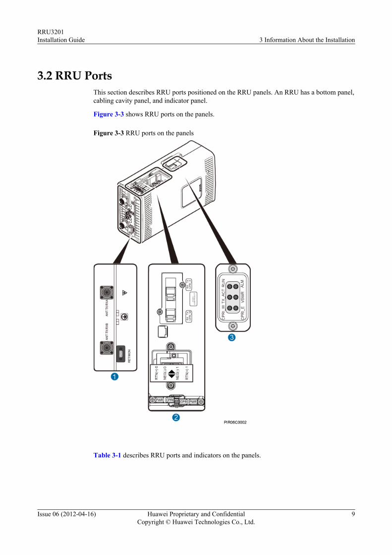
3.2 RRU PortsThis section describes RRU ports positioned on the RRU panels. An RRU has a bottom panel,cabling cavity panel, and indicator panel.
Figure 3-3 shows RRU ports on the panels.
Figure 3-3 RRU ports on the panels
Table 3-1 describes RRU ports and indicators on the panels.
RRU3201Installation Guide 3 Information About the Installation
Issue 06 (2012-04-16) Huawei Proprietary and ConfidentialCopyright © Huawei Technologies Co., Ltd.
9
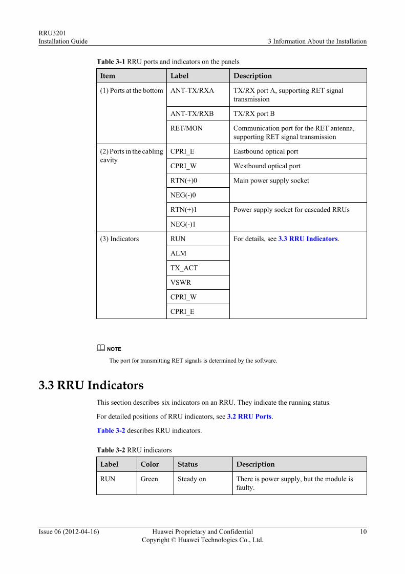
Table 3-1 RRU ports and indicators on the panels
Item Label Description
(1) Ports at the bottom ANT-TX/RXA TX/RX port A, supporting RET signaltransmission
ANT-TX/RXB TX/RX port B
RET/MON Communication port for the RET antenna,supporting RET signal transmission
(2) Ports in the cablingcavity
CPRI_E Eastbound optical port
CPRI_W Westbound optical port
RTN(+)0 Main power supply socket
NEG(-)0
RTN(+)1 Power supply socket for cascaded RRUs
NEG(-)1
(3) Indicators RUN For details, see 3.3 RRU Indicators.
ALM
TX_ACT
VSWR
CPRI_W
CPRI_E
NOTE
The port for transmitting RET signals is determined by the software.
3.3 RRU IndicatorsThis section describes six indicators on an RRU. They indicate the running status.
For detailed positions of RRU indicators, see 3.2 RRU Ports.
Table 3-2 describes RRU indicators.
Table 3-2 RRU indicators
Label Color Status Description
RUN Green Steady on There is power supply, but the module isfaulty.
RRU3201Installation Guide 3 Information About the Installation
Issue 06 (2012-04-16) Huawei Proprietary and ConfidentialCopyright © Huawei Technologies Co., Ltd.
10
Label Color Status Description
Steady off There is no power supply, or the module isfaulty.
Blinking (on for1s and off for 1s)
The module is working properly.
Blinking (on for0.125s and off for0.125s)
Software is being loaded to the module, or themodule is not started.
ALM Red Steady on Alarms are generated, and the module mustbe replaced.
Blinking (on for1s and off for 1s)
Alarms are generated. The alarms may becaused by the faults on the related boards orports. Therefore, the necessity for modulereplacement is uncertain.
Steady off No alarm is generated.
TX_ACT Green Steady on The module is working properly with TXchannels enabled.
Blinking (on for1s and off for 1s)
The module is working properly with TXchannels disabled.
VSWR Red Steady off No VSWR alarm is generated.
Steady on VSWR alarms are generated on the ANT-TX/RXA port.
Blinking (on for1s and off for 1s)
VSWR alarms are generated on the ANT-TX/RXB port.
Blinking (on for0.125s and off for0.125s)
VSWR alarms are generated on the ANT-TX/RXA and ANT-TX/RXB ports.
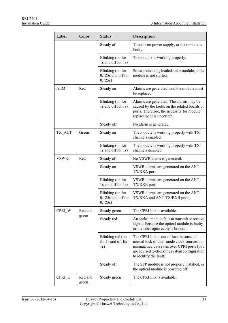
CPRI_W Red andgreen
Steady green The CPRI link is available.
Steady red An optical module fails to transmit or receivesignals because the optical module is faultyor the fiber optic cable is broken.
Blinking red (onfor 1s and off for1s)
The CPRI link is out of lock because ofmutual lock of dual-mode clock sources ormismatched data rates over CPRI ports (youare advised to check the system configurationto identify the fault).
Steady off The SFP module is not properly installed, orthe optical module is powered off.
CPRI_E Red andgreen
Steady green The CPRI link is available.
RRU3201Installation Guide 3 Information About the Installation
Issue 06 (2012-04-16) Huawei Proprietary and ConfidentialCopyright © Huawei Technologies Co., Ltd.
11
Label Color Status Description
Steady red An optical module fails to transmit or receivesignals because the optical module is faultyor the fiber optic cable is broken.
Blinking red (onfor 1s and off for1s)
The CPRI link is out of lock because ofmutual lock of dual-mode clock sources ormismatched data rates over CPRI ports (youare advised to check the system configurationto identify the fault).
Steady off The SFP module is not properly installed, orthe optical module is powered off.
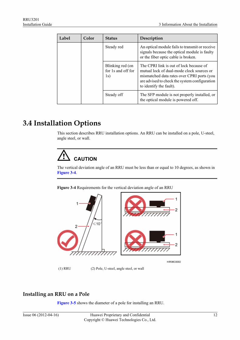
3.4 Installation OptionsThis section describes RRU installation options. An RRU can be installed on a pole, U-steel,angle steel, or wall.
CAUTIONThe vertical deviation angle of an RRU must be less than or equal to 10 degrees, as shown inFigure 3-4.
Figure 3-4 Requirements for the vertical deviation angle of an RRU
(1) RRU (2) Pole, U-steel, angle steel, or wall
Installing an RRU on a PoleFigure 3-5 shows the diameter of a pole for installing an RRU.
RRU3201Installation Guide 3 Information About the Installation
Issue 06 (2012-04-16) Huawei Proprietary and ConfidentialCopyright © Huawei Technologies Co., Ltd.
12
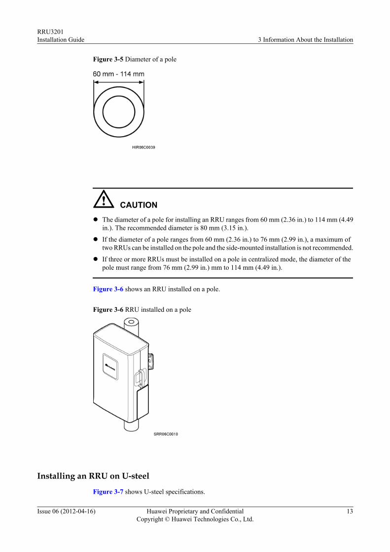
Figure 3-5 Diameter of a pole
CAUTIONl The diameter of a pole for installing an RRU ranges from 60 mm (2.36 in.) to 114 mm (4.49
in.). The recommended diameter is 80 mm (3.15 in.).
l If the diameter of a pole ranges from 60 mm (2.36 in.) to 76 mm (2.99 in.), a maximum oftwo RRUs can be installed on the pole and the side-mounted installation is not recommended.
l If three or more RRUs must be installed on a pole in centralized mode, the diameter of thepole must range from 76 mm (2.99 in.) mm to 114 mm (4.49 in.).
Figure 3-6 shows an RRU installed on a pole.
Figure 3-6 RRU installed on a pole
Installing an RRU on U-steel
Figure 3-7 shows U-steel specifications.
RRU3201Installation Guide 3 Information About the Installation
Issue 06 (2012-04-16) Huawei Proprietary and ConfidentialCopyright © Huawei Technologies Co., Ltd.
13
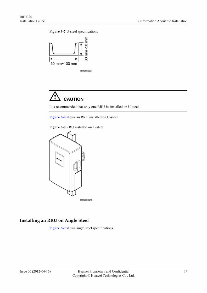
Figure 3-7 U-steel specifications
CAUTIONIt is recommended that only one RRU be installed on U-steel.
Figure 3-8 shows an RRU installed on U-steel.
Figure 3-8 RRU installed on U-steel
Installing an RRU on Angle SteelFigure 3-9 shows angle steel specifications.
RRU3201Installation Guide 3 Information About the Installation
Issue 06 (2012-04-16) Huawei Proprietary and ConfidentialCopyright © Huawei Technologies Co., Ltd.
14
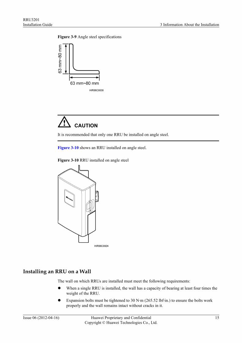
Figure 3-9 Angle steel specifications
CAUTIONIt is recommended that only one RRU be installed on angle steel.
Figure 3-10 shows an RRU installed on angle steel.
Figure 3-10 RRU installed on angle steel
Installing an RRU on a Wall
The wall on which RRUs are installed must meet the following requirements:
l When a single RRU is installed, the wall has a capacity of bearing at least four times theweight of the RRU.
l Expansion bolts must be tightened to 30 N·m (265.52 lbf·in.) to ensure the bolts workproperly and the wall remains intact without cracks in it.
RRU3201Installation Guide 3 Information About the Installation
Issue 06 (2012-04-16) Huawei Proprietary and ConfidentialCopyright © Huawei Technologies Co., Ltd.
15
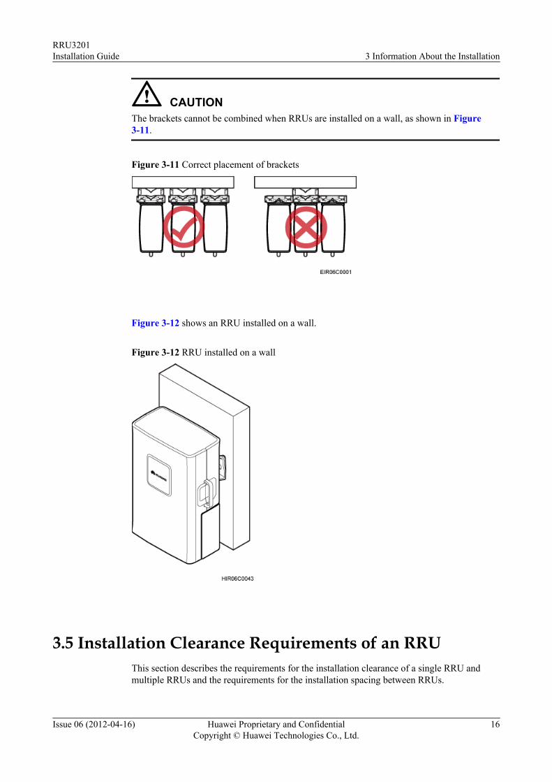
CAUTIONThe brackets cannot be combined when RRUs are installed on a wall, as shown in Figure3-11.
Figure 3-11 Correct placement of brackets
Figure 3-12 shows an RRU installed on a wall.
Figure 3-12 RRU installed on a wall
3.5 Installation Clearance Requirements of an RRUThis section describes the requirements for the installation clearance of a single RRU andmultiple RRUs and the requirements for the installation spacing between RRUs.
RRU3201Installation Guide 3 Information About the Installation
Issue 06 (2012-04-16) Huawei Proprietary and ConfidentialCopyright © Huawei Technologies Co., Ltd.
16
NOTE
The recommended installation clearance ensures normal running and provides an appropriate space forOperation and Maintenance (O&M). If there is sufficient space, leave the recommended installationclearance.
The minimum installation clearance ensures normal running and heat dissipation, but OM activities suchas checking indicator status and opening the maintenance cavity cannot be properly conducted. If theinstallation space is restricted, leave the minimum installation clearance.
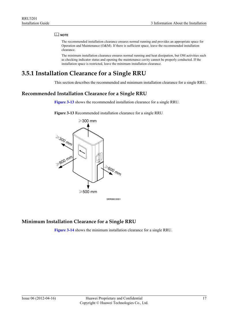
3.5.1 Installation Clearance for a Single RRUThis section describes the recommended and minimum installation clearance for a single RRU.
Recommended Installation Clearance for a Single RRUFigure 3-13 shows the recommended installation clearance for a single RRU.
Figure 3-13 Recommended installation clearance for a single RRU
Minimum Installation Clearance for a Single RRUFigure 3-14 shows the minimum installation clearance for a single RRU.
RRU3201Installation Guide 3 Information About the Installation
Issue 06 (2012-04-16) Huawei Proprietary and ConfidentialCopyright © Huawei Technologies Co., Ltd.
17
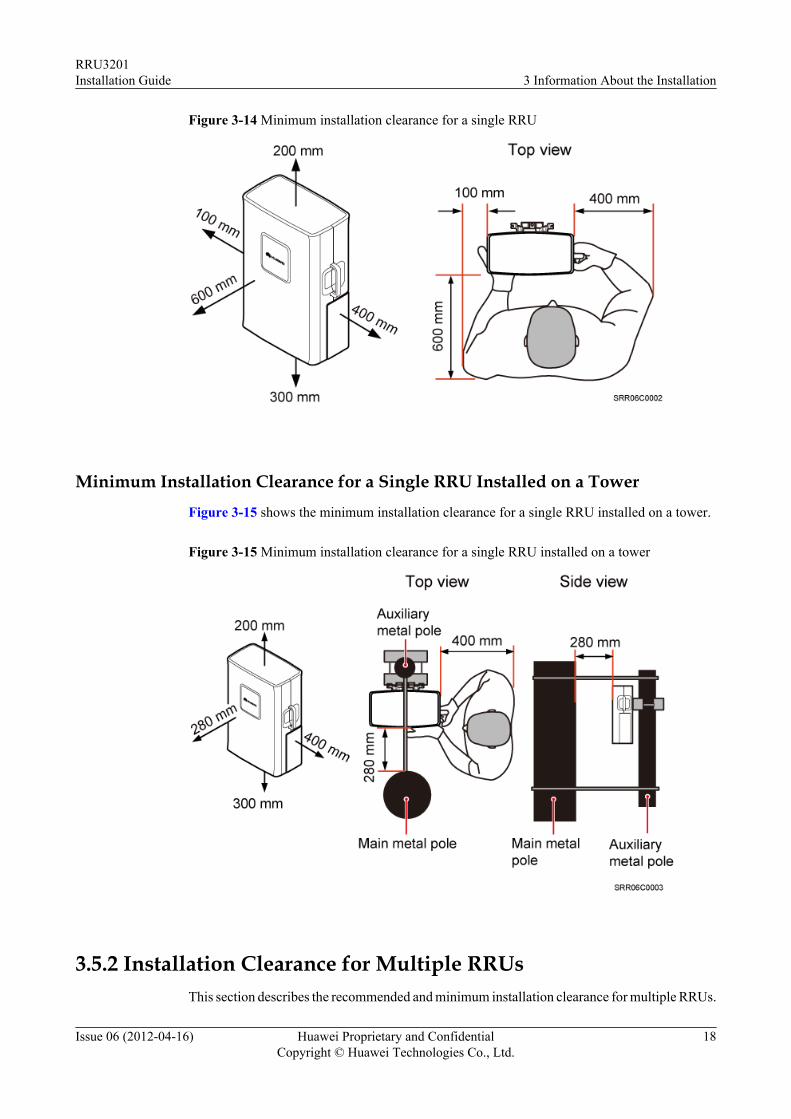
Figure 3-14 Minimum installation clearance for a single RRU
Minimum Installation Clearance for a Single RRU Installed on a Tower
Figure 3-15 shows the minimum installation clearance for a single RRU installed on a tower.
Figure 3-15 Minimum installation clearance for a single RRU installed on a tower
3.5.2 Installation Clearance for Multiple RRUsThis section describes the recommended and minimum installation clearance for multiple RRUs.
RRU3201Installation Guide 3 Information About the Installation
Issue 06 (2012-04-16) Huawei Proprietary and ConfidentialCopyright © Huawei Technologies Co., Ltd.
18
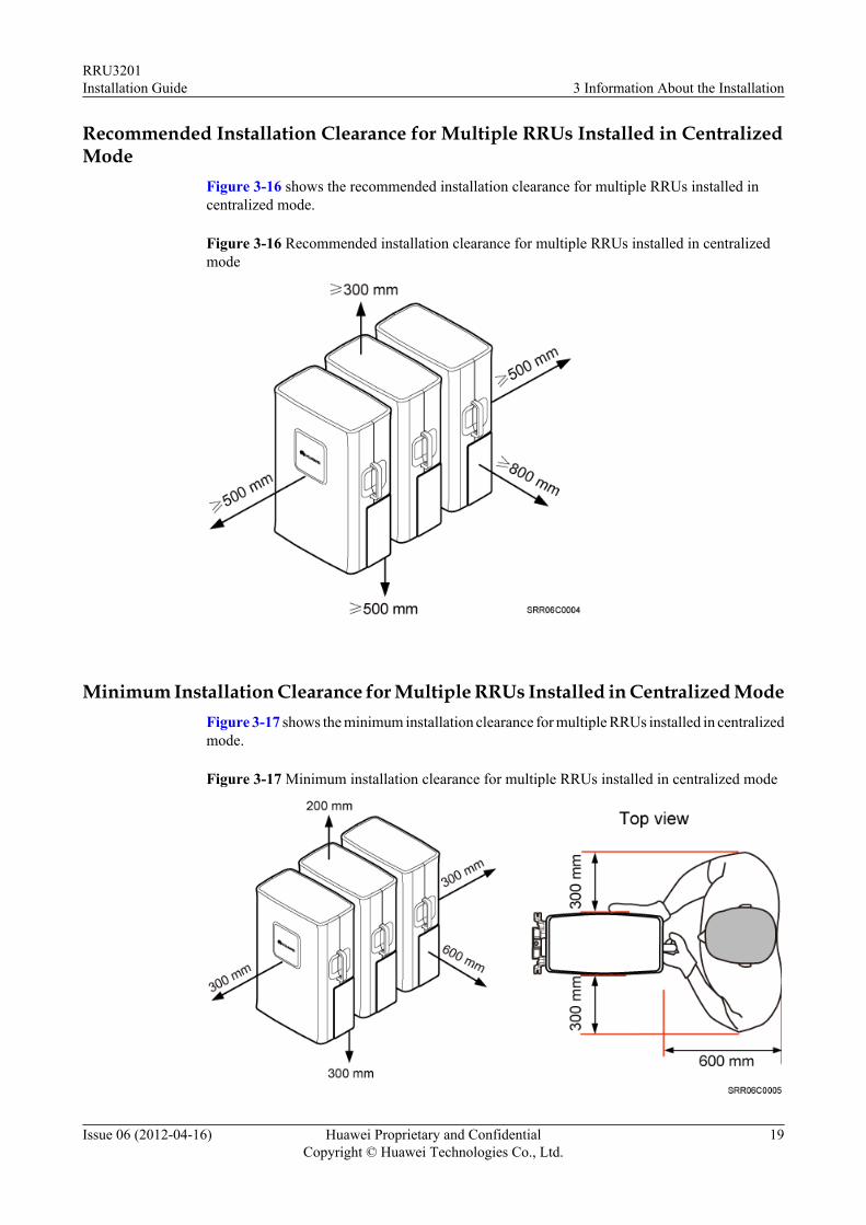
Recommended Installation Clearance for Multiple RRUs Installed in CentralizedMode
Figure 3-16 shows the recommended installation clearance for multiple RRUs installed incentralized mode.
Figure 3-16 Recommended installation clearance for multiple RRUs installed in centralizedmode
Minimum Installation Clearance for Multiple RRUs Installed in Centralized ModeFigure 3-17 shows the minimum installation clearance for multiple RRUs installed in centralizedmode.
Figure 3-17 Minimum installation clearance for multiple RRUs installed in centralized mode
RRU3201Installation Guide 3 Information About the Installation
Issue 06 (2012-04-16) Huawei Proprietary and ConfidentialCopyright © Huawei Technologies Co., Ltd.
19
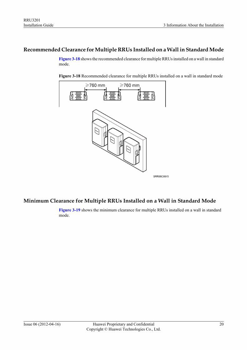
Recommended Clearance for Multiple RRUs Installed on a Wall in Standard ModeFigure 3-18 shows the recommended clearance for multiple RRUs installed on a wall in standardmode.
Figure 3-18 Recommended clearance for multiple RRUs installed on a wall in standard mode
Minimum Clearance for Multiple RRUs Installed on a Wall in Standard ModeFigure 3-19 shows the minimum clearance for multiple RRUs installed on a wall in standardmode.
RRU3201Installation Guide 3 Information About the Installation
Issue 06 (2012-04-16) Huawei Proprietary and ConfidentialCopyright © Huawei Technologies Co., Ltd.
20
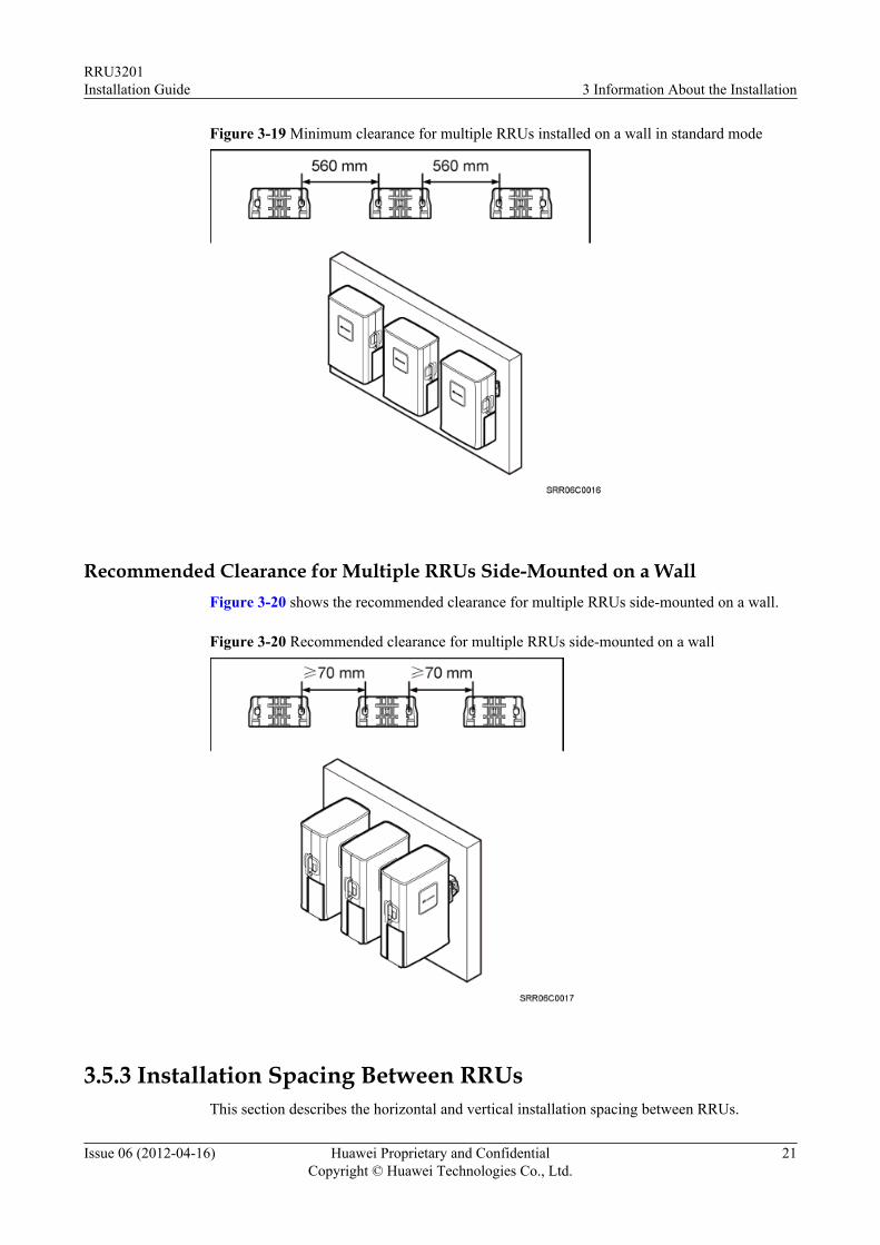
Figure 3-19 Minimum clearance for multiple RRUs installed on a wall in standard mode
Recommended Clearance for Multiple RRUs Side-Mounted on a WallFigure 3-20 shows the recommended clearance for multiple RRUs side-mounted on a wall.
Figure 3-20 Recommended clearance for multiple RRUs side-mounted on a wall
3.5.3 Installation Spacing Between RRUsThis section describes the horizontal and vertical installation spacing between RRUs.
RRU3201Installation Guide 3 Information About the Installation
Issue 06 (2012-04-16) Huawei Proprietary and ConfidentialCopyright © Huawei Technologies Co., Ltd.
21
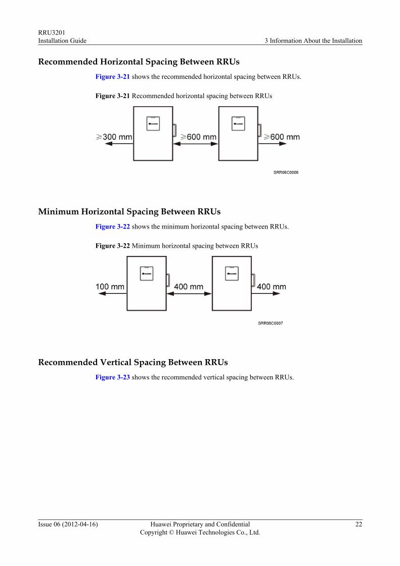
Recommended Horizontal Spacing Between RRUsFigure 3-21 shows the recommended horizontal spacing between RRUs.
Figure 3-21 Recommended horizontal spacing between RRUs
Minimum Horizontal Spacing Between RRUsFigure 3-22 shows the minimum horizontal spacing between RRUs.
Figure 3-22 Minimum horizontal spacing between RRUs
Recommended Vertical Spacing Between RRUsFigure 3-23 shows the recommended vertical spacing between RRUs.
RRU3201Installation Guide 3 Information About the Installation
Issue 06 (2012-04-16) Huawei Proprietary and ConfidentialCopyright © Huawei Technologies Co., Ltd.
22
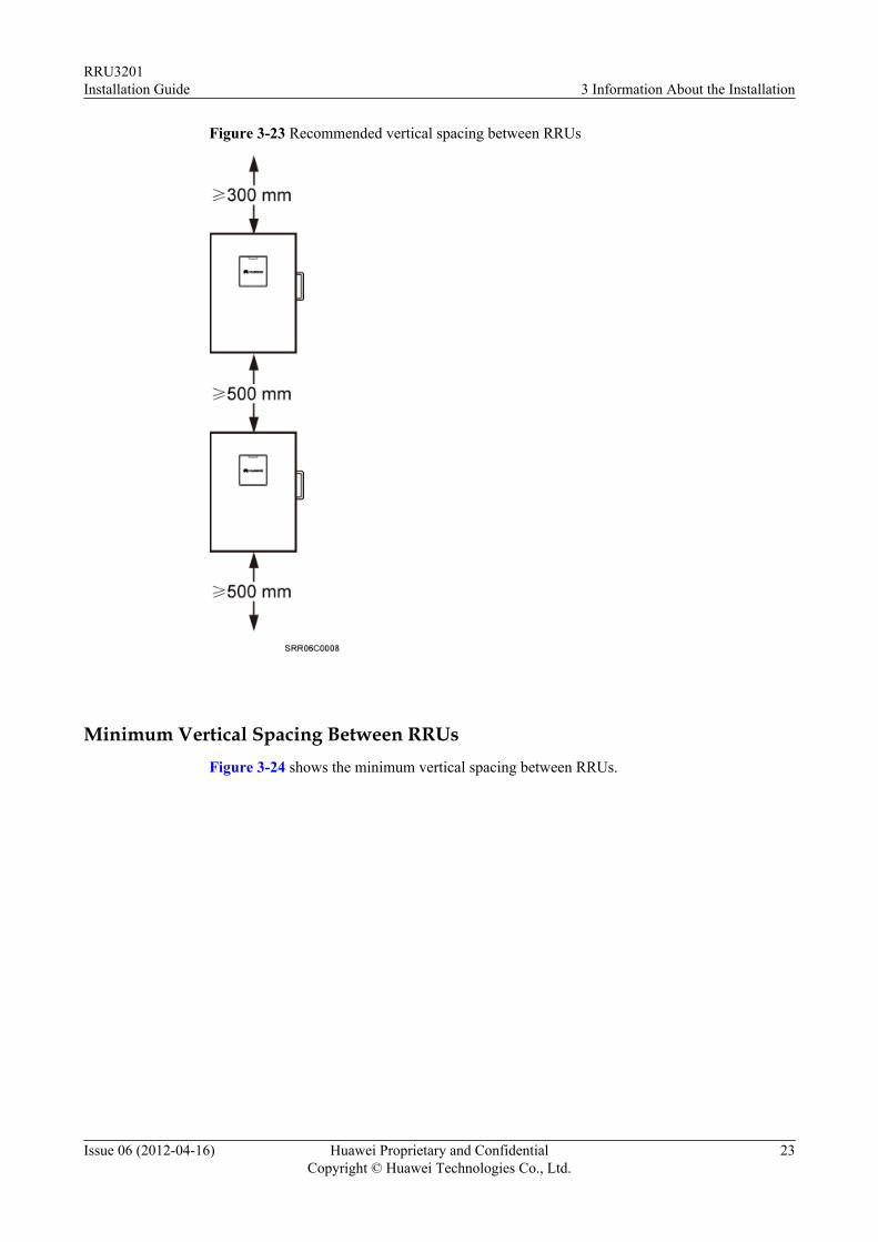
Figure 3-23 Recommended vertical spacing between RRUs
Minimum Vertical Spacing Between RRUsFigure 3-24 shows the minimum vertical spacing between RRUs.
RRU3201Installation Guide 3 Information About the Installation
Issue 06 (2012-04-16) Huawei Proprietary and ConfidentialCopyright © Huawei Technologies Co., Ltd.
23
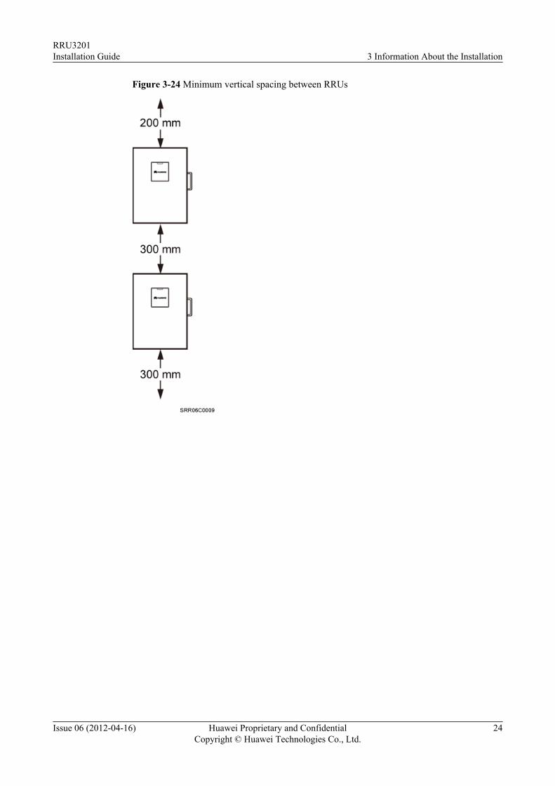
Figure 3-24 Minimum vertical spacing between RRUs
RRU3201Installation Guide 3 Information About the Installation
Issue 06 (2012-04-16) Huawei Proprietary and ConfidentialCopyright © Huawei Technologies Co., Ltd.
24
4 Unpacking the Equipment
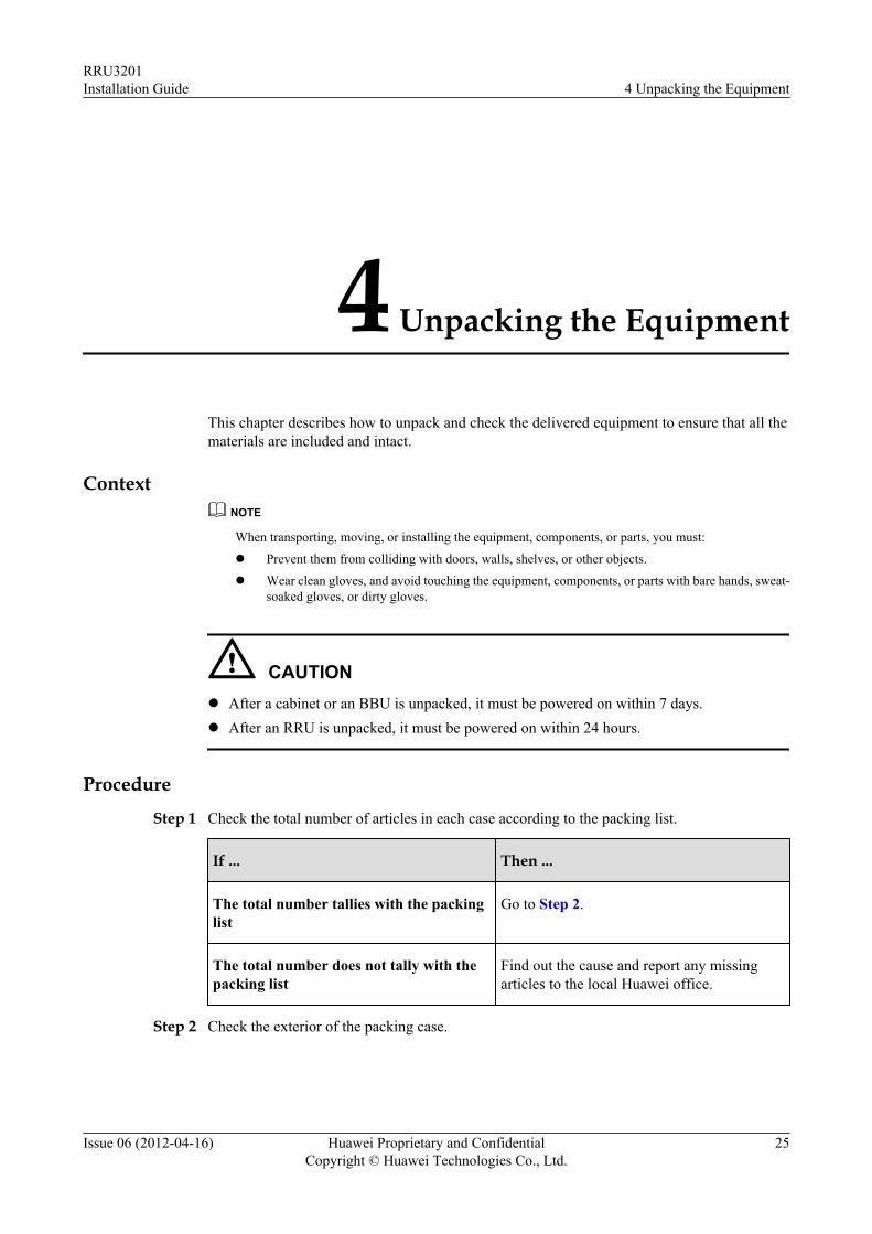
This chapter describes how to unpack and check the delivered equipment to ensure that all thematerials are included and intact.
ContextNOTE
When transporting, moving, or installing the equipment, components, or parts, you must:
l Prevent them from colliding with doors, walls, shelves, or other objects.
l Wear clean gloves, and avoid touching the equipment, components, or parts with bare hands, sweat-soaked gloves, or dirty gloves.
CAUTIONl After a cabinet or an BBU is unpacked, it must be powered on within 7 days.l After an RRU is unpacked, it must be powered on within 24 hours.
Procedure
Step 1 Check the total number of articles in each case according to the packing list.
If ... Then ...
The total number tallies with the packinglist
Go to Step 2.
The total number does not tally with thepacking list
Find out the cause and report any missingarticles to the local Huawei office.
Step 2 Check the exterior of the packing case.
RRU3201Installation Guide 4 Unpacking the Equipment
Issue 06 (2012-04-16) Huawei Proprietary and ConfidentialCopyright © Huawei Technologies Co., Ltd.
25
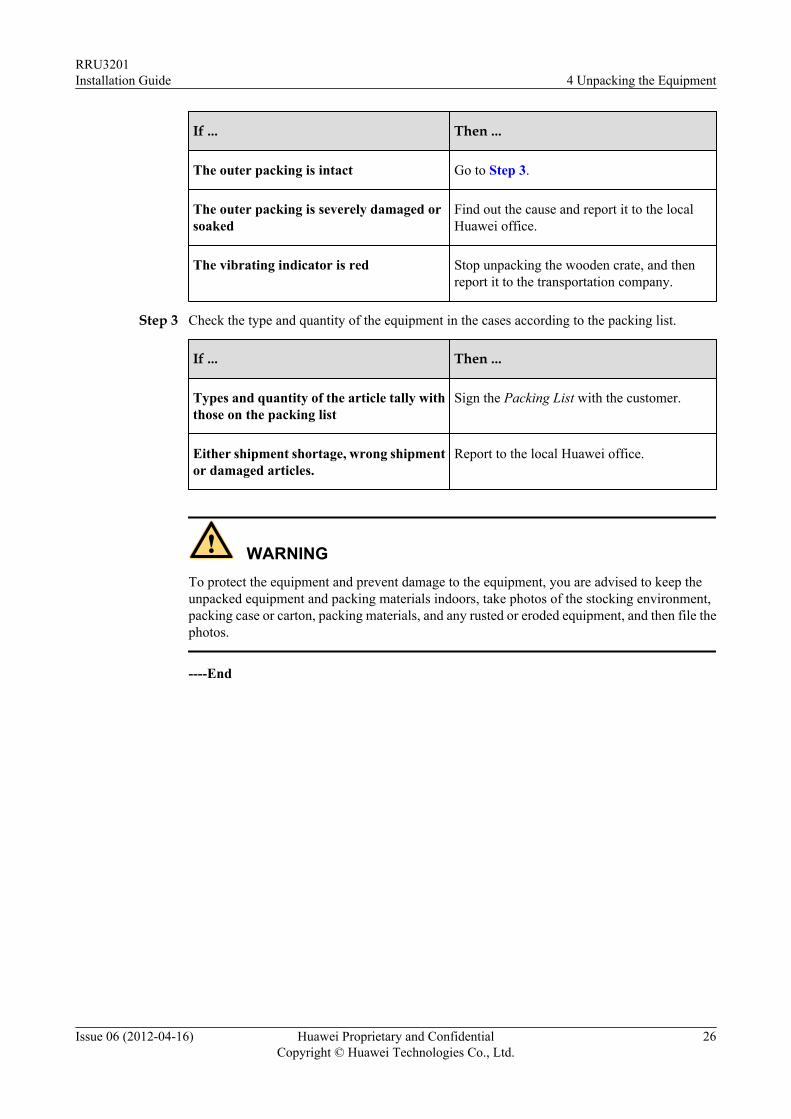
If ... Then ...
The outer packing is intact Go to Step 3.
The outer packing is severely damaged orsoaked
Find out the cause and report it to the localHuawei office.
The vibrating indicator is red Stop unpacking the wooden crate, and thenreport it to the transportation company.
Step 3 Check the type and quantity of the equipment in the cases according to the packing list.
If ... Then ...
Types and quantity of the article tally withthose on the packing list
Sign the Packing List with the customer.
Either shipment shortage, wrong shipmentor damaged articles.
Report to the local Huawei office.
WARNINGTo protect the equipment and prevent damage to the equipment, you are advised to keep theunpacked equipment and packing materials indoors, take photos of the stocking environment,packing case or carton, packing materials, and any rusted or eroded equipment, and then file thephotos.
----End
RRU3201Installation Guide 4 Unpacking the Equipment
Issue 06 (2012-04-16) Huawei Proprietary and ConfidentialCopyright © Huawei Technologies Co., Ltd.
26
5 Installation Process
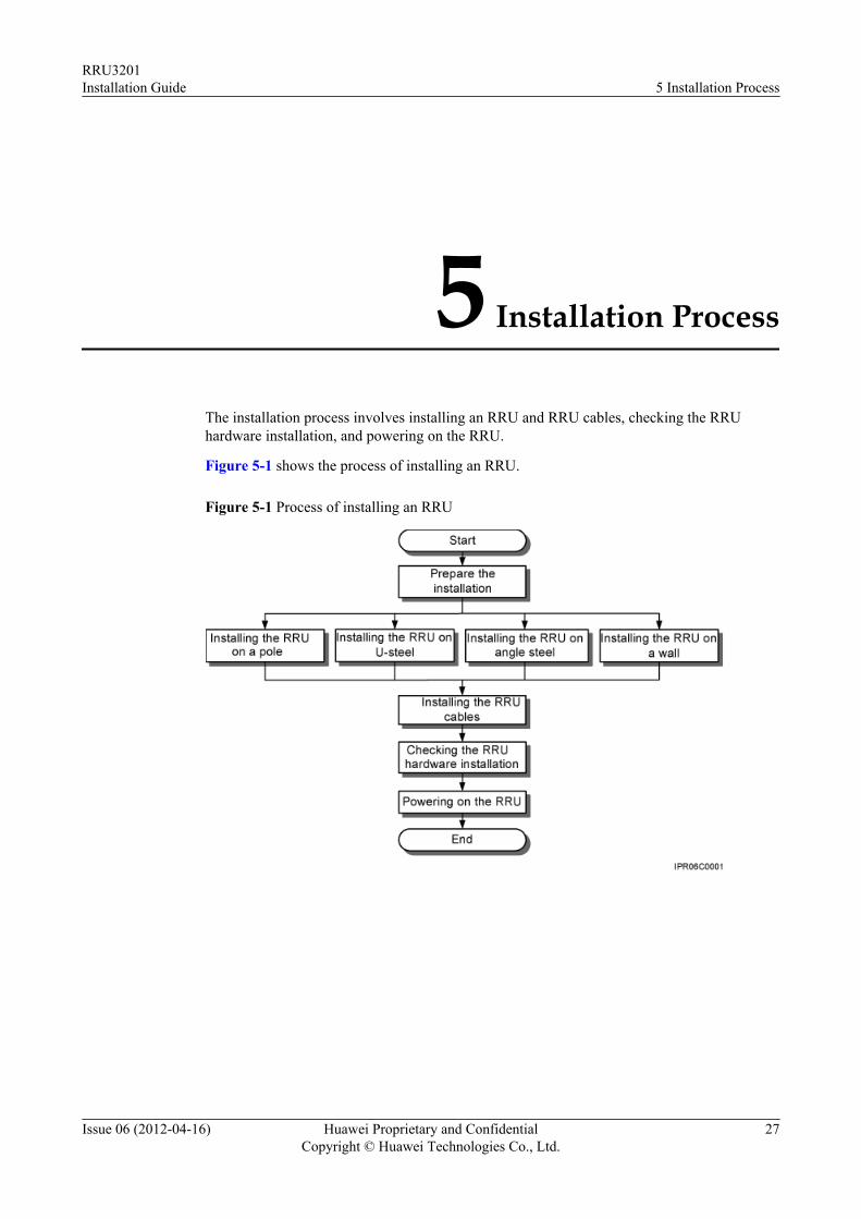
The installation process involves installing an RRU and RRU cables, checking the RRUhardware installation, and powering on the RRU.
Figure 5-1 shows the process of installing an RRU.
Figure 5-1 Process of installing an RRU
RRU3201Installation Guide 5 Installation Process
Issue 06 (2012-04-16) Huawei Proprietary and ConfidentialCopyright © Huawei Technologies Co., Ltd.
27
6 Hoisting an RRU and Related Cables onto aTower
About This Chapter
This section describes the procedure for hoisting an RRU and related cables onto a tower andthe precautions that must be taken.
6.1 Hoisting an RRU onto a TowerBefore installing an RRU on a tower, bind the RRU and mounting kits and then hoist them ontothe tower. The RRU can be installed on a pole, U-steel, or angle steel. This section describes theprocedure for hoisting the RRU and mounting kits onto the tower and the precautions that mustbe taken.
6.2 Hoisting Fiber Optic Cables onto a TowerThis section describes the procedure for hoisting fiber optic cables onto a tower and theprecautions that must be taken.
6.3 Hoisting Power Cables onto a TowerThis section describes the procedure for hoisting power cables onto a tower and the precautionsthat must be taken.
RRU3201Installation Guide 6 Hoisting an RRU and Related Cables onto a Tower
Issue 06 (2012-04-16) Huawei Proprietary and ConfidentialCopyright © Huawei Technologies Co., Ltd.
28
6.1 Hoisting an RRU onto a TowerBefore installing an RRU on a tower, bind the RRU and mounting kits and then hoist them ontothe tower. The RRU can be installed on a pole, U-steel, or angle steel. This section describes theprocedure for hoisting the RRU and mounting kits onto the tower and the precautions that mustbe taken.
Prerequisites
Place a foam pad or cardboard on the ground to protect the housing of the RRU from damagebefore the binding. Do not stand the RRU upright because the load-bearing capacity of the RFports at the RRU bottom is low.
CAUTIONWhen installed on a tower, only one RRU can be installed in standard mode or reverse mode.Two RRUs cannot be installed on the side or on a pole in back-to-back mode, and the bracketsfor more than two RRUs cannot be combined.
Procedure
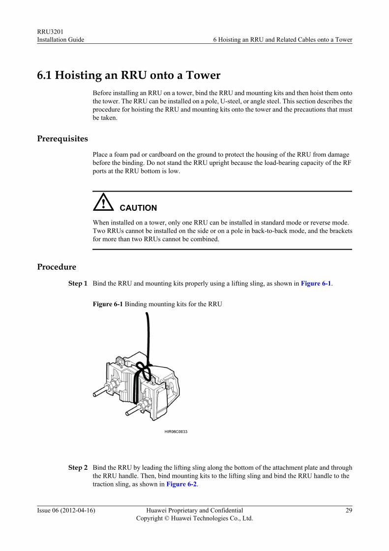
Step 1 Bind the RRU and mounting kits properly using a lifting sling, as shown in Figure 6-1.
Figure 6-1 Binding mounting kits for the RRU
Step 2 Bind the RRU by leading the lifting sling along the bottom of the attachment plate and throughthe RRU handle. Then, bind mounting kits to the lifting sling and bind the RRU handle to thetraction sling, as shown in Figure 6-2.
RRU3201Installation Guide 6 Hoisting an RRU and Related Cables onto a Tower
Issue 06 (2012-04-16) Huawei Proprietary and ConfidentialCopyright © Huawei Technologies Co., Ltd.
29
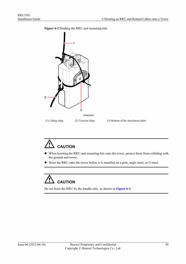
Figure 6-2 Binding the RRU and mounting kits
(1) Lifting sling (2) Traction sling (3) Bottom of the attachment plate
CAUTIONl When hoisting the RRU and mounting kits onto the tower, protect them from colliding with
the ground and tower.l Hoist the RRU onto the tower before it is installed on a pole, angle steel, or U-steel.
CAUTIONDo not hoist the RRU by the handle only, as shown in Figure 6-3.
RRU3201Installation Guide 6 Hoisting an RRU and Related Cables onto a Tower
Issue 06 (2012-04-16) Huawei Proprietary and ConfidentialCopyright © Huawei Technologies Co., Ltd.
30
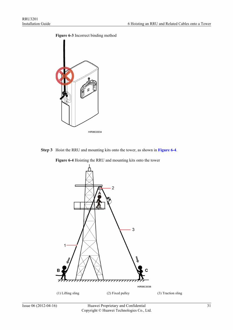
Figure 6-3 Incorrect binding method
Step 3 Hoist the RRU and mounting kits onto the tower, as shown in Figure 6-4.
Figure 6-4 Hoisting the RRU and mounting kits onto the tower
(1) Lifting sling (2) Fixed pulley (3) Traction sling
RRU3201Installation Guide 6 Hoisting an RRU and Related Cables onto a Tower
Issue 06 (2012-04-16) Huawei Proprietary and ConfidentialCopyright © Huawei Technologies Co., Ltd.
31
1. After climbing up to the tower, installation engineer A secures the fixed pulley to the tower
platform support and leads the lifting sling through the fixed pulley.2. Installation engineer C binds the RRU and mounting kits using the lifting sling and secures
the traction sling to the RRU handle.3. Installation engineer B pulls the lifting sling downwards, and installation engineer C pulls
the traction sling outwards to protect the RRU and mounting kits from colliding with thetower.
4. Installation engineer A catches the RRU and mounting kits and then unties the sling.
NOTE
The procedure for hoisting the RRU and mounting kits onto the tower is for your reference only.
----End
6.2 Hoisting Fiber Optic Cables onto a TowerThis section describes the procedure for hoisting fiber optic cables onto a tower and theprecautions that must be taken.
ContextCabling requirements for power cables are met. For details, see 8.1 Cabling Requirements.
Procedure
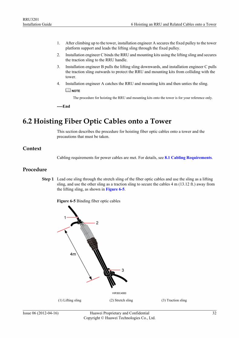
Step 1 Lead one sling through the stretch sling of the fiber optic cables and use the sling as a liftingsling, and use the other sling as a traction sling to secure the cables 4 m (13.12 ft.) away fromthe lifting sling, as shown in Figure 6-5.
Figure 6-5 Binding fiber optic cables
(1) Lifting sling (2) Stretch sling (3) Traction sling
RRU3201Installation Guide 6 Hoisting an RRU and Related Cables onto a Tower
Issue 06 (2012-04-16) Huawei Proprietary and ConfidentialCopyright © Huawei Technologies Co., Ltd.
32
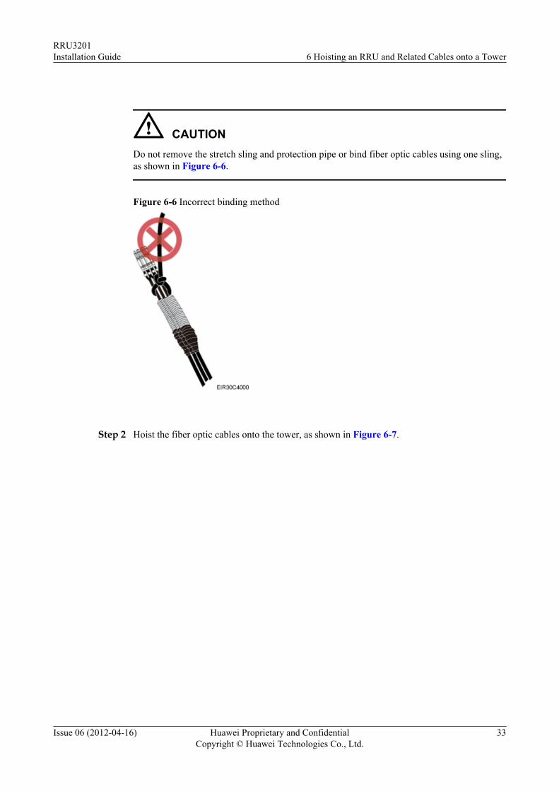
CAUTIONDo not remove the stretch sling and protection pipe or bind fiber optic cables using one sling,as shown in Figure 6-6.
Figure 6-6 Incorrect binding method
Step 2 Hoist the fiber optic cables onto the tower, as shown in Figure 6-7.
RRU3201Installation Guide 6 Hoisting an RRU and Related Cables onto a Tower
Issue 06 (2012-04-16) Huawei Proprietary and ConfidentialCopyright © Huawei Technologies Co., Ltd.
33
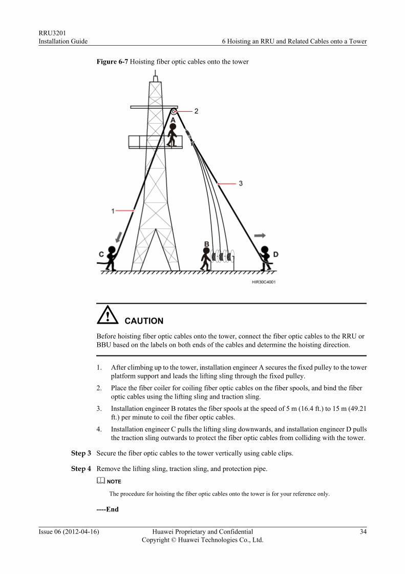
Figure 6-7 Hoisting fiber optic cables onto the tower
CAUTIONBefore hoisting fiber optic cables onto the tower, connect the fiber optic cables to the RRU orBBU based on the labels on both ends of the cables and determine the hoisting direction.
1. After climbing up to the tower, installation engineer A secures the fixed pulley to the towerplatform support and leads the lifting sling through the fixed pulley.
2. Place the fiber coiler for coiling fiber optic cables on the fiber spools, and bind the fiberoptic cables using the lifting sling and traction sling.
3. Installation engineer B rotates the fiber spools at the speed of 5 m (16.4 ft.) to 15 m (49.21ft.) per minute to coil the fiber optic cables.
4. Installation engineer C pulls the lifting sling downwards, and installation engineer D pullsthe traction sling outwards to protect the fiber optic cables from colliding with the tower.
Step 3 Secure the fiber optic cables to the tower vertically using cable clips.
Step 4 Remove the lifting sling, traction sling, and protection pipe.
NOTE
The procedure for hoisting the fiber optic cables onto the tower is for your reference only.
----End
RRU3201Installation Guide 6 Hoisting an RRU and Related Cables onto a Tower
Issue 06 (2012-04-16) Huawei Proprietary and ConfidentialCopyright © Huawei Technologies Co., Ltd.
34
6.3 Hoisting Power Cables onto a TowerThis section describes the procedure for hoisting power cables onto a tower and the precautionsthat must be taken.
ContextCabling requirements for power cables are met. For details, see 8.1 Cabling Requirements.
Procedure
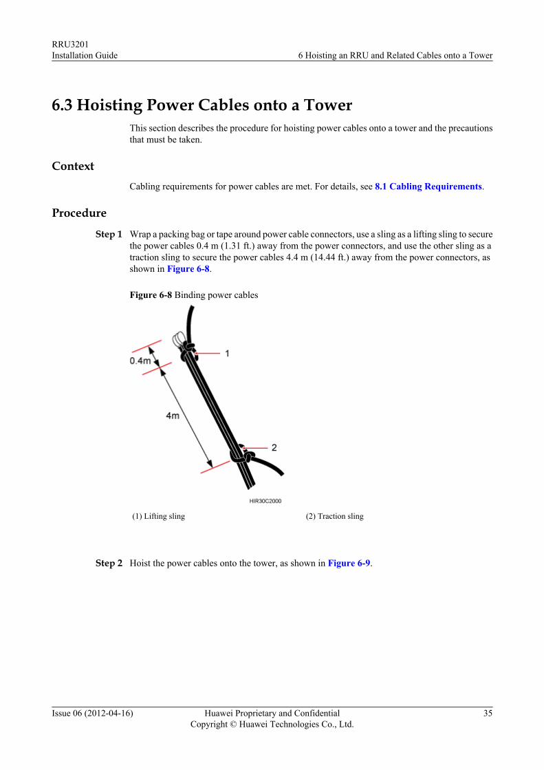
Step 1 Wrap a packing bag or tape around power cable connectors, use a sling as a lifting sling to securethe power cables 0.4 m (1.31 ft.) away from the power connectors, and use the other sling as atraction sling to secure the power cables 4.4 m (14.44 ft.) away from the power connectors, asshown in Figure 6-8.
Figure 6-8 Binding power cables
(1) Lifting sling (2) Traction sling
Step 2 Hoist the power cables onto the tower, as shown in Figure 6-9.
RRU3201Installation Guide 6 Hoisting an RRU and Related Cables onto a Tower
Issue 06 (2012-04-16) Huawei Proprietary and ConfidentialCopyright © Huawei Technologies Co., Ltd.
35
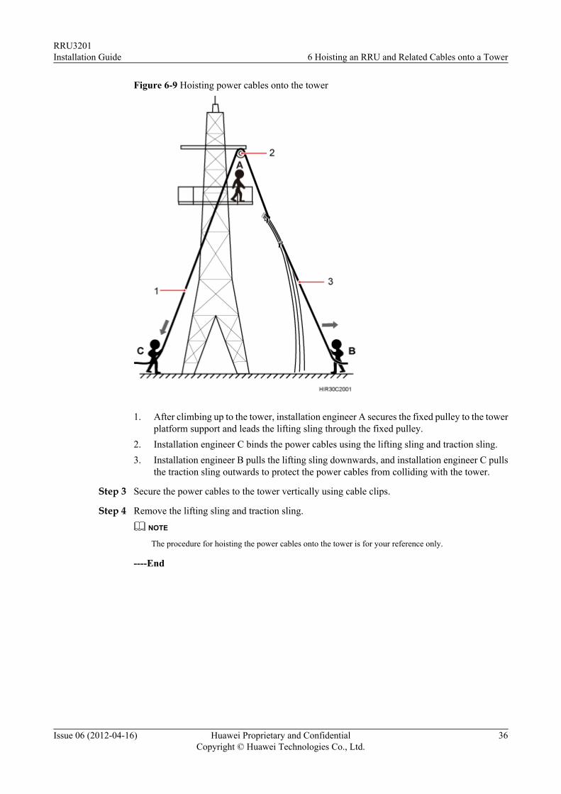
Figure 6-9 Hoisting power cables onto the tower
1. After climbing up to the tower, installation engineer A secures the fixed pulley to the towerplatform support and leads the lifting sling through the fixed pulley.
2. Installation engineer C binds the power cables using the lifting sling and traction sling.3. Installation engineer B pulls the lifting sling downwards, and installation engineer C pulls
the traction sling outwards to protect the power cables from colliding with the tower.
Step 3 Secure the power cables to the tower vertically using cable clips.
Step 4 Remove the lifting sling and traction sling.
NOTE
The procedure for hoisting the power cables onto the tower is for your reference only.
----End
RRU3201Installation Guide 6 Hoisting an RRU and Related Cables onto a Tower
Issue 06 (2012-04-16) Huawei Proprietary and ConfidentialCopyright © Huawei Technologies Co., Ltd.
36
7 Installing the RRU
About This Chapter
This chapter describes the procedure for installing the RRU. The RRU can be installed on a pole,U-steel, angle steel, or wall. The procedure for installing the RRU varies depending oninstallation options.
CAUTIONl Do not stand the RRU upright because the load-bearing capacity of the RF ports at the RRU
bottom is low.l Place a foam pad or cardboard under an RRU to protect the RRU housing from damage
during the installation.
7.1 Mounting Kits for an RRUThis section describes the bracket assembly and the attachment plate for an RRU.
7.2 Installing the RRU on a PoleOne or more RRUs can be installed on a pole.
7.3 Installing the RRU on U-steelThis section describes the procedure for installing the RRU on U-steel and the precautions thatmust be taken during the installation. The RRU installed on U-steel can be mounted to a toweror placed on the ground. It is recommended that only one RRU be installed on U-steel.
7.4 Installing the RRU on Angle SteelThis section describes the procedure for installing the RRU on angle steel and the precautionsthat must be taken during the installation. The RRU installed on angle steel can be mounted toa tower or placed on the ground. It is recommended that only one RRU be installed on anglesteel.
7.5 Installing the RRU on a WallThis section describes the procedure for installing the RRU on a wall and the precautions thatmust be taken during the installation.
RRU3201Installation Guide 7 Installing the RRU
Issue 06 (2012-04-16) Huawei Proprietary and ConfidentialCopyright © Huawei Technologies Co., Ltd.
37
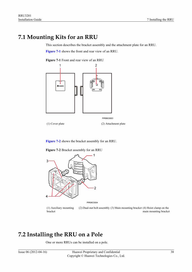
7.1 Mounting Kits for an RRUThis section describes the bracket assembly and the attachment plate for an RRU.
Figure 7-1 shows the front and rear view of an RRU.
Figure 7-1 Front and rear view of an RRU
(1) Cover plate (2) Attachment plate
Figure 7-2 shows the bracket assembly for an RRU.
Figure 7-2 Bracket assembly for an RRU
(1) Auxiliary mountingbracket
(2) Dual-nut bolt assembly (3) Main mounting bracket (4) Hoist clamp on themain mounting bracket
7.2 Installing the RRU on a PoleOne or more RRUs can be installed on a pole.
RRU3201Installation Guide 7 Installing the RRU
Issue 06 (2012-04-16) Huawei Proprietary and ConfidentialCopyright © Huawei Technologies Co., Ltd.
38
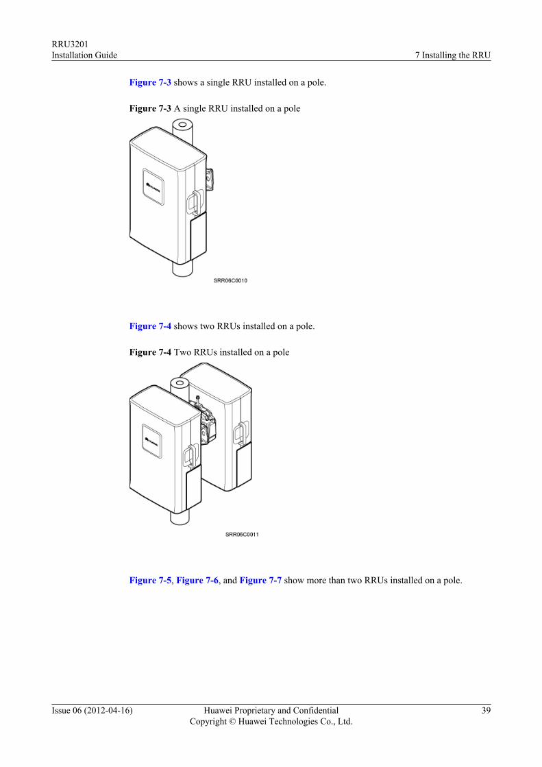
Figure 7-3 shows a single RRU installed on a pole.
Figure 7-3 A single RRU installed on a pole
Figure 7-4 shows two RRUs installed on a pole.
Figure 7-4 Two RRUs installed on a pole
Figure 7-5, Figure 7-6, and Figure 7-7 show more than two RRUs installed on a pole.
RRU3201Installation Guide 7 Installing the RRU
Issue 06 (2012-04-16) Huawei Proprietary and ConfidentialCopyright © Huawei Technologies Co., Ltd.
39
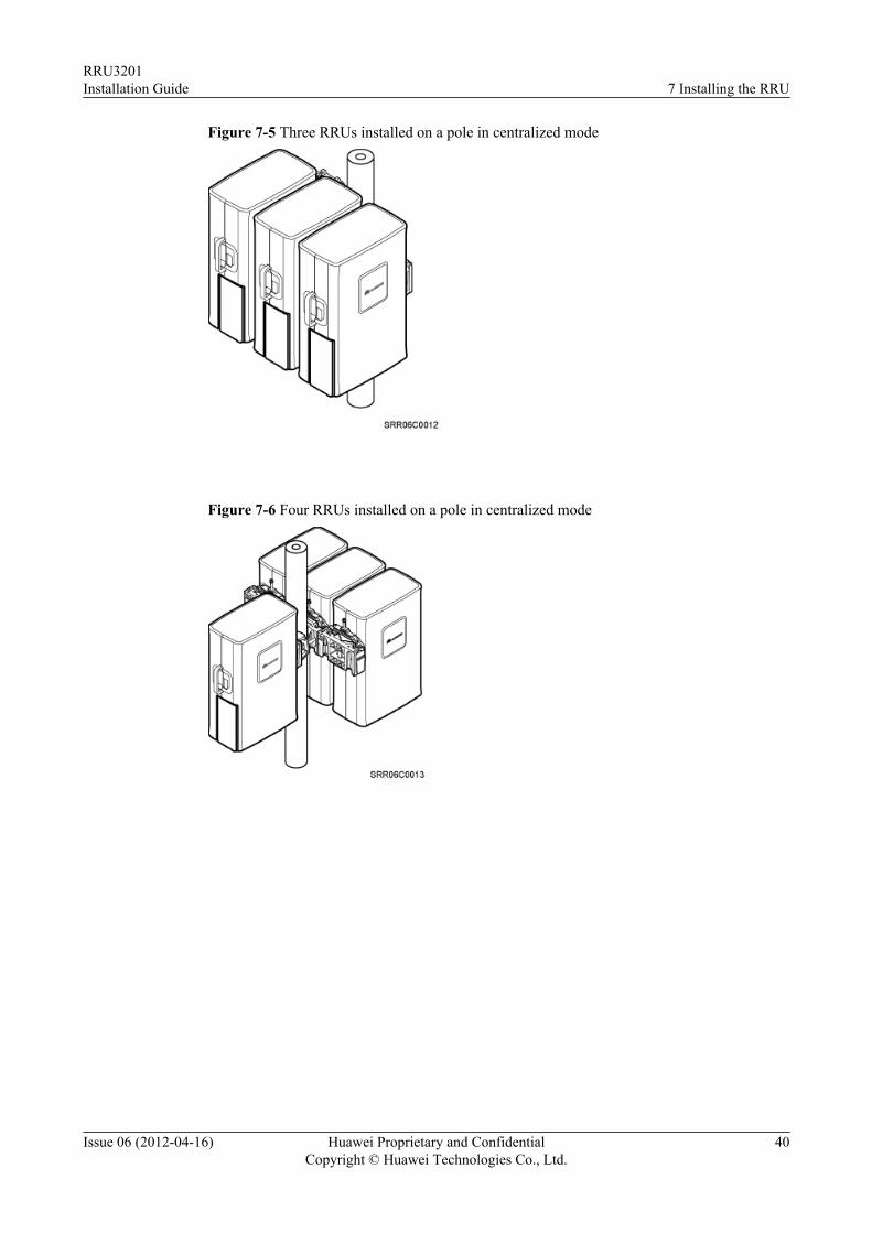
Figure 7-5 Three RRUs installed on a pole in centralized mode
Figure 7-6 Four RRUs installed on a pole in centralized mode
RRU3201Installation Guide 7 Installing the RRU
Issue 06 (2012-04-16) Huawei Proprietary and ConfidentialCopyright © Huawei Technologies Co., Ltd.
40
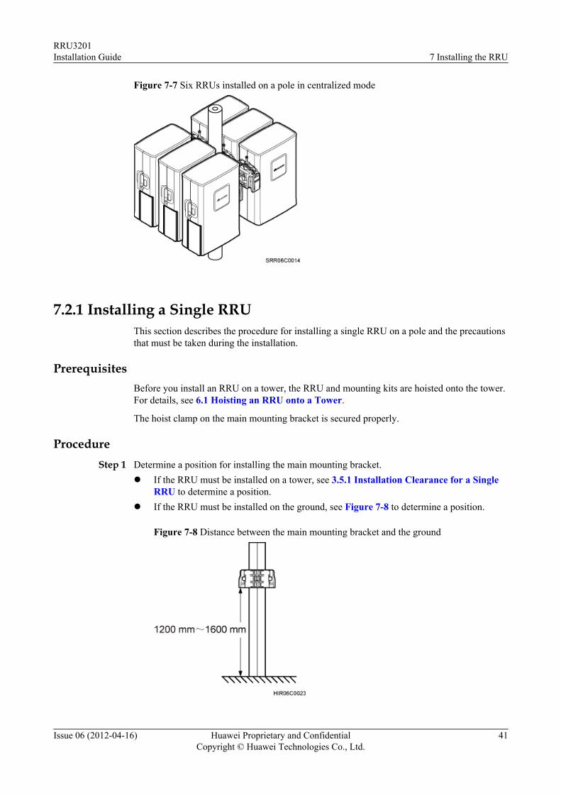
Figure 7-7 Six RRUs installed on a pole in centralized mode
7.2.1 Installing a Single RRUThis section describes the procedure for installing a single RRU on a pole and the precautionsthat must be taken during the installation.
PrerequisitesBefore you install an RRU on a tower, the RRU and mounting kits are hoisted onto the tower.For details, see 6.1 Hoisting an RRU onto a Tower.
The hoist clamp on the main mounting bracket is secured properly.
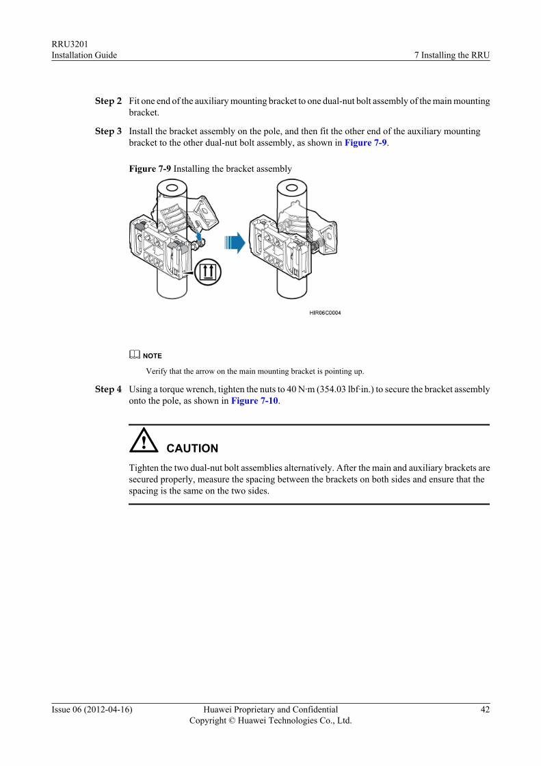
ProcedureStep 1 Determine a position for installing the main mounting bracket.
l If the RRU must be installed on a tower, see 3.5.1 Installation Clearance for a SingleRRU to determine a position.
l If the RRU must be installed on the ground, see Figure 7-8 to determine a position.
Figure 7-8 Distance between the main mounting bracket and the ground
RRU3201Installation Guide 7 Installing the RRU
Issue 06 (2012-04-16) Huawei Proprietary and ConfidentialCopyright © Huawei Technologies Co., Ltd.
41
Step 2 Fit one end of the auxiliary mounting bracket to one dual-nut bolt assembly of the main mountingbracket.
Step 3 Install the bracket assembly on the pole, and then fit the other end of the auxiliary mountingbracket to the other dual-nut bolt assembly, as shown in Figure 7-9.
Figure 7-9 Installing the bracket assembly
NOTE
Verify that the arrow on the main mounting bracket is pointing up.
Step 4 Using a torque wrench, tighten the nuts to 40 N·m (354.03 lbf·in.) to secure the bracket assemblyonto the pole, as shown in Figure 7-10.
CAUTIONTighten the two dual-nut bolt assemblies alternatively. After the main and auxiliary brackets aresecured properly, measure the spacing between the brackets on both sides and ensure that thespacing is the same on the two sides.
RRU3201Installation Guide 7 Installing the RRU
Issue 06 (2012-04-16) Huawei Proprietary and ConfidentialCopyright © Huawei Technologies Co., Ltd.
42
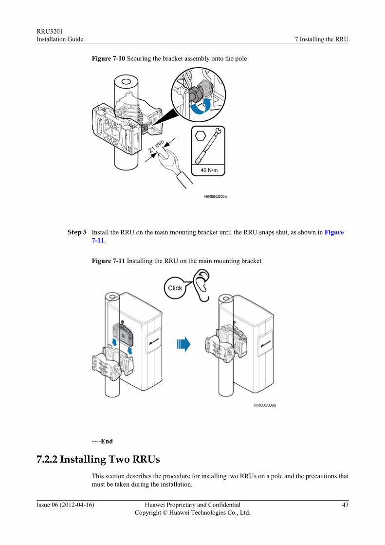
Figure 7-10 Securing the bracket assembly onto the pole
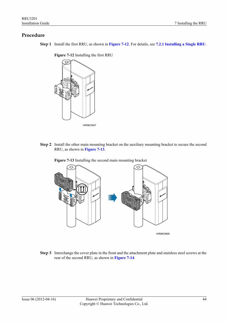
Step 5 Install the RRU on the main mounting bracket until the RRU snaps shut, as shown in Figure7-11.
Figure 7-11 Installing the RRU on the main mounting bracket
----End
7.2.2 Installing Two RRUsThis section describes the procedure for installing two RRUs on a pole and the precautions thatmust be taken during the installation.
RRU3201Installation Guide 7 Installing the RRU
Issue 06 (2012-04-16) Huawei Proprietary and ConfidentialCopyright © Huawei Technologies Co., Ltd.
43
Procedure
Step 1 Install the first RRU, as shown in Figure 7-12. For details, see 7.2.1 Installing a Single RRU.
Figure 7-12 Installing the first RRU
Step 2 Install the other main mounting bracket on the auxiliary mounting bracket to secure the secondRRU, as shown in Figure 7-13.
Figure 7-13 Installing the second main mounting bracket
Step 3 Interchange the cover plate in the front and the attachment plate and stainless steel screws at therear of the second RRU, as shown in Figure 7-14.
RRU3201Installation Guide 7 Installing the RRU
Issue 06 (2012-04-16) Huawei Proprietary and ConfidentialCopyright © Huawei Technologies Co., Ltd.
44
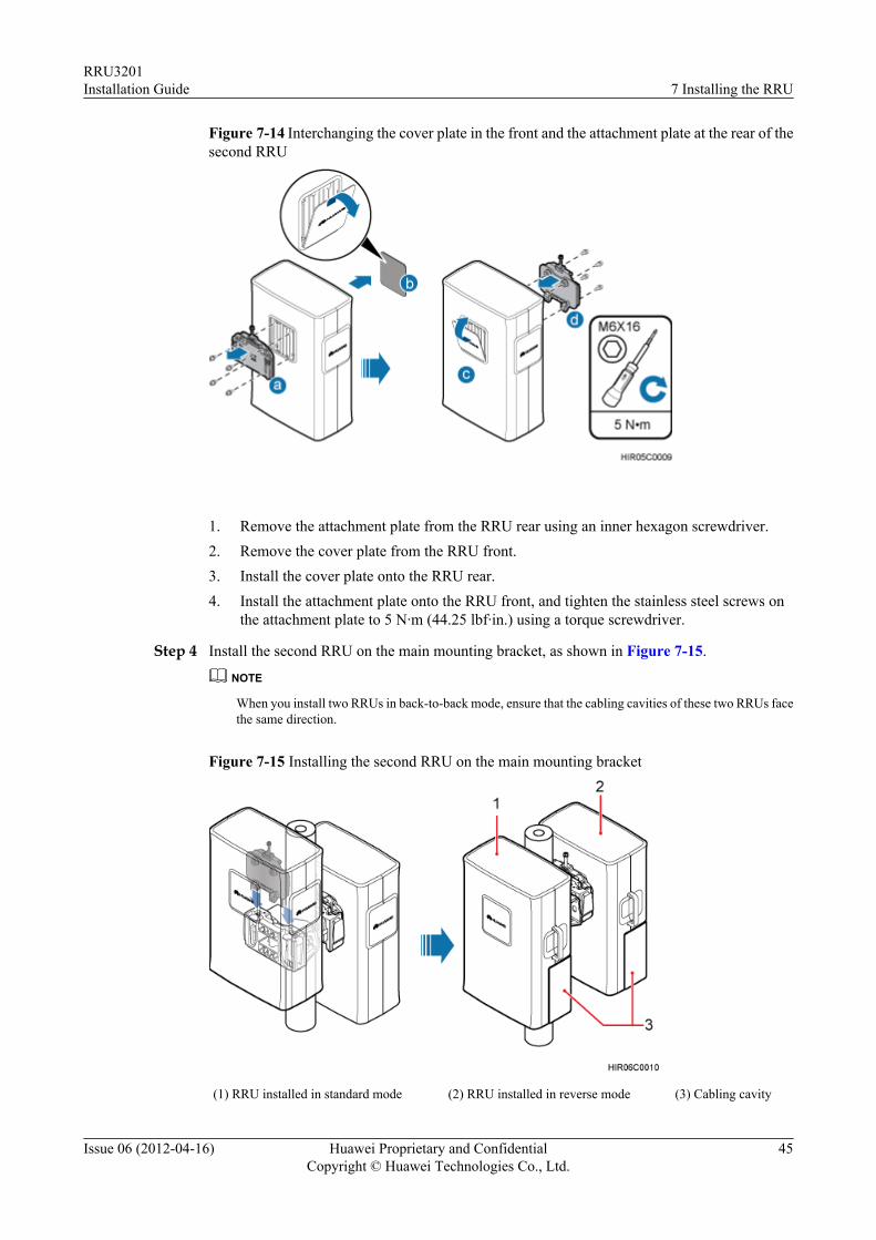
Figure 7-14 Interchanging the cover plate in the front and the attachment plate at the rear of thesecond RRU
1. Remove the attachment plate from the RRU rear using an inner hexagon screwdriver.2. Remove the cover plate from the RRU front.3. Install the cover plate onto the RRU rear.4. Install the attachment plate onto the RRU front, and tighten the stainless steel screws on
the attachment plate to 5 N·m (44.25 lbf·in.) using a torque screwdriver.
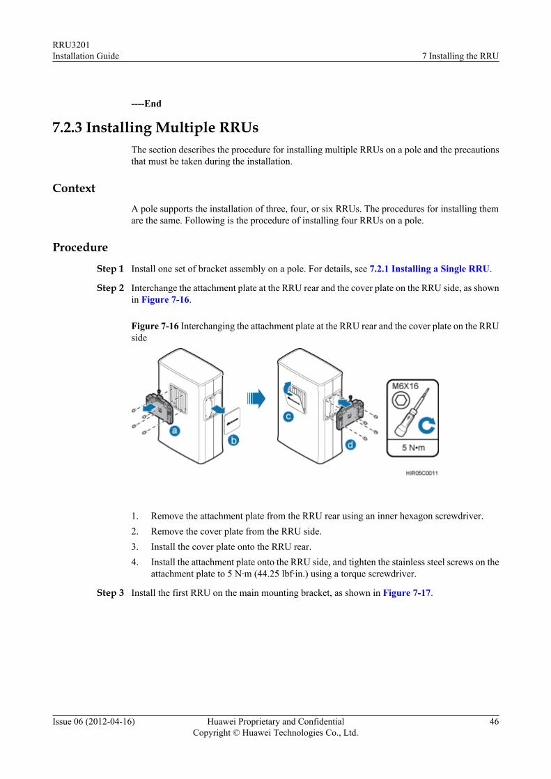
Step 4 Install the second RRU on the main mounting bracket, as shown in Figure 7-15.
NOTE
When you install two RRUs in back-to-back mode, ensure that the cabling cavities of these two RRUs facethe same direction.
Figure 7-15 Installing the second RRU on the main mounting bracket
(1) RRU installed in standard mode (2) RRU installed in reverse mode (3) Cabling cavity
RRU3201Installation Guide 7 Installing the RRU
Issue 06 (2012-04-16) Huawei Proprietary and ConfidentialCopyright © Huawei Technologies Co., Ltd.
45
----End
7.2.3 Installing Multiple RRUsThe section describes the procedure for installing multiple RRUs on a pole and the precautionsthat must be taken during the installation.
ContextA pole supports the installation of three, four, or six RRUs. The procedures for installing themare the same. Following is the procedure of installing four RRUs on a pole.
Procedure
Step 1 Install one set of bracket assembly on a pole. For details, see 7.2.1 Installing a Single RRU.
Step 2 Interchange the attachment plate at the RRU rear and the cover plate on the RRU side, as shownin Figure 7-16.
Figure 7-16 Interchanging the attachment plate at the RRU rear and the cover plate on the RRUside
1. Remove the attachment plate from the RRU rear using an inner hexagon screwdriver.2. Remove the cover plate from the RRU side.3. Install the cover plate onto the RRU rear.4. Install the attachment plate onto the RRU side, and tighten the stainless steel screws on the
attachment plate to 5 N·m (44.25 lbf·in.) using a torque screwdriver.
Step 3 Install the first RRU on the main mounting bracket, as shown in Figure 7-17.
RRU3201Installation Guide 7 Installing the RRU
Issue 06 (2012-04-16) Huawei Proprietary and ConfidentialCopyright © Huawei Technologies Co., Ltd.
46
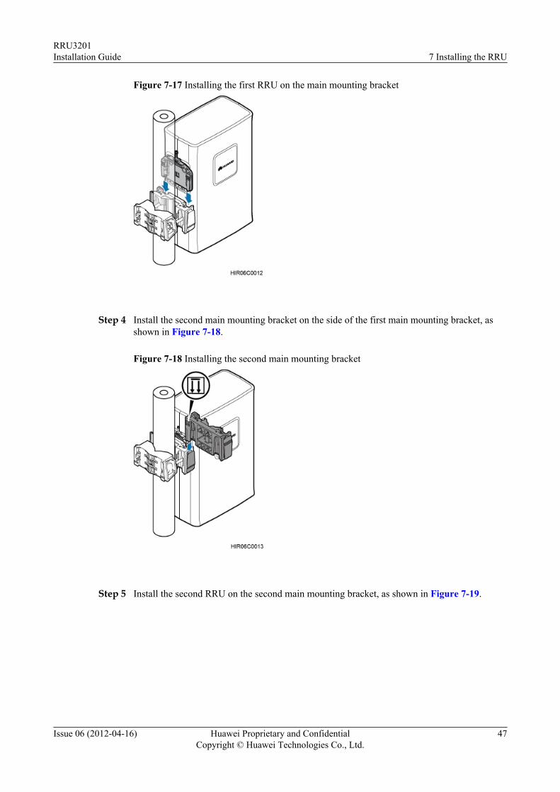
Figure 7-17 Installing the first RRU on the main mounting bracket
Step 4 Install the second main mounting bracket on the side of the first main mounting bracket, asshown in Figure 7-18.
Figure 7-18 Installing the second main mounting bracket
Step 5 Install the second RRU on the second main mounting bracket, as shown in Figure 7-19.
RRU3201Installation Guide 7 Installing the RRU
Issue 06 (2012-04-16) Huawei Proprietary and ConfidentialCopyright © Huawei Technologies Co., Ltd.
47
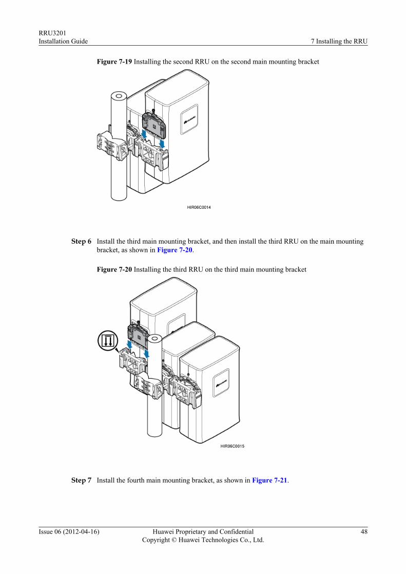
Figure 7-19 Installing the second RRU on the second main mounting bracket
Step 6 Install the third main mounting bracket, and then install the third RRU on the main mountingbracket, as shown in Figure 7-20.
Figure 7-20 Installing the third RRU on the third main mounting bracket
Step 7 Install the fourth main mounting bracket, as shown in Figure 7-21.
RRU3201Installation Guide 7 Installing the RRU
Issue 06 (2012-04-16) Huawei Proprietary and ConfidentialCopyright © Huawei Technologies Co., Ltd.
48
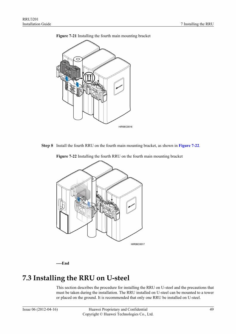
Figure 7-21 Installing the fourth main mounting bracket
Step 8 Install the fourth RRU on the fourth main mounting bracket, as shown in Figure 7-22.
Figure 7-22 Installing the fourth RRU on the fourth main mounting bracket
----End
7.3 Installing the RRU on U-steelThis section describes the procedure for installing the RRU on U-steel and the precautions thatmust be taken during the installation. The RRU installed on U-steel can be mounted to a toweror placed on the ground. It is recommended that only one RRU be installed on U-steel.
RRU3201Installation Guide 7 Installing the RRU
Issue 06 (2012-04-16) Huawei Proprietary and ConfidentialCopyright © Huawei Technologies Co., Ltd.
49
PrerequisitesBefore you install an RRU on a tower, the RRU and mounting kits are hoisted onto the tower.For details, see 6.1 Hoisting an RRU onto a Tower.
The hoist clamp on the main mounting bracket is secured properly.
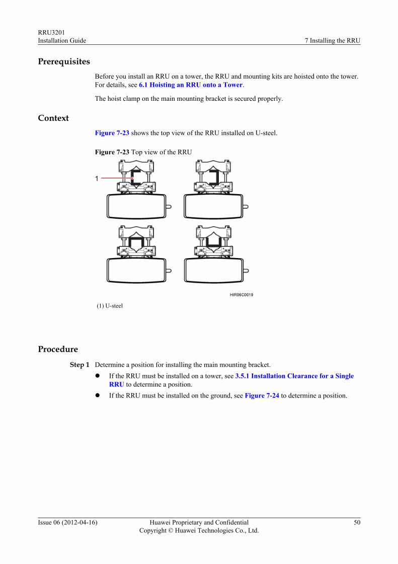
ContextFigure 7-23 shows the top view of the RRU installed on U-steel.
Figure 7-23 Top view of the RRU
(1) U-steel
Procedure
Step 1 Determine a position for installing the main mounting bracket.l If the RRU must be installed on a tower, see 3.5.1 Installation Clearance for a Single
RRU to determine a position.l If the RRU must be installed on the ground, see Figure 7-24 to determine a position.
RRU3201Installation Guide 7 Installing the RRU
Issue 06 (2012-04-16) Huawei Proprietary and ConfidentialCopyright © Huawei Technologies Co., Ltd.
50
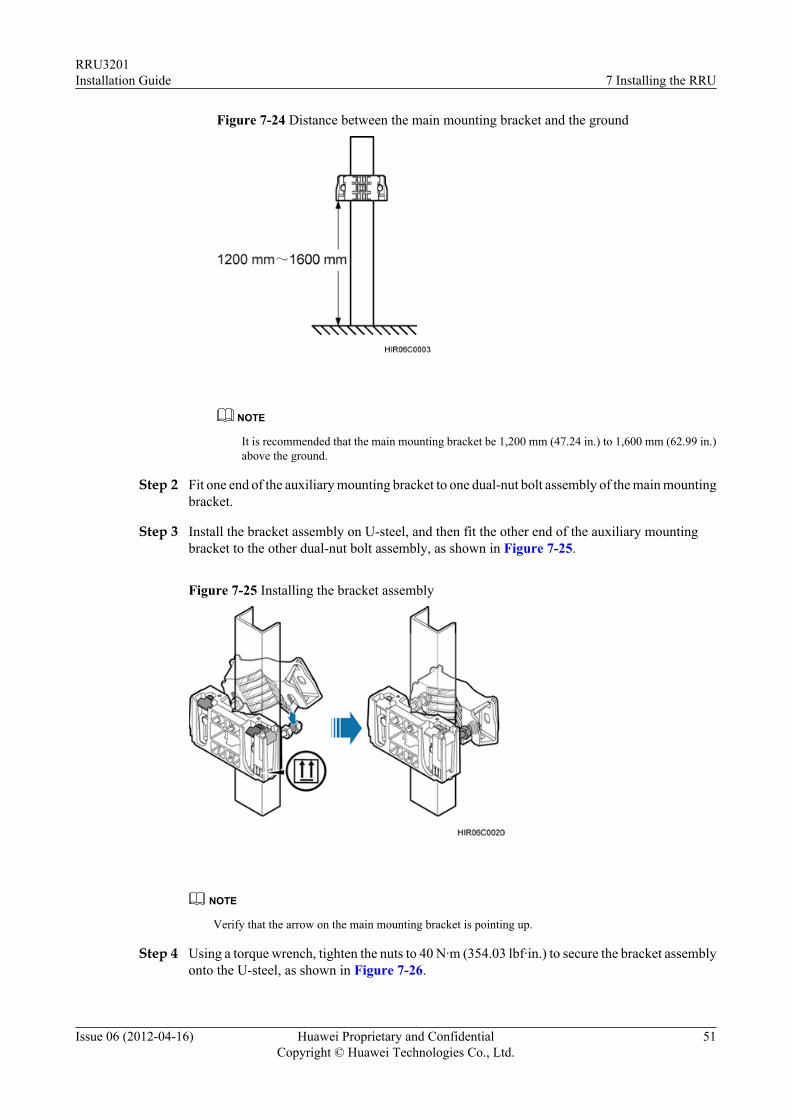
Figure 7-24 Distance between the main mounting bracket and the ground
NOTE
It is recommended that the main mounting bracket be 1,200 mm (47.24 in.) to 1,600 mm (62.99 in.)above the ground.
Step 2 Fit one end of the auxiliary mounting bracket to one dual-nut bolt assembly of the main mountingbracket.
Step 3 Install the bracket assembly on U-steel, and then fit the other end of the auxiliary mountingbracket to the other dual-nut bolt assembly, as shown in Figure 7-25.
Figure 7-25 Installing the bracket assembly
NOTE
Verify that the arrow on the main mounting bracket is pointing up.
Step 4 Using a torque wrench, tighten the nuts to 40 N·m (354.03 lbf·in.) to secure the bracket assemblyonto the U-steel, as shown in Figure 7-26.
RRU3201Installation Guide 7 Installing the RRU
Issue 06 (2012-04-16) Huawei Proprietary and ConfidentialCopyright © Huawei Technologies Co., Ltd.
51
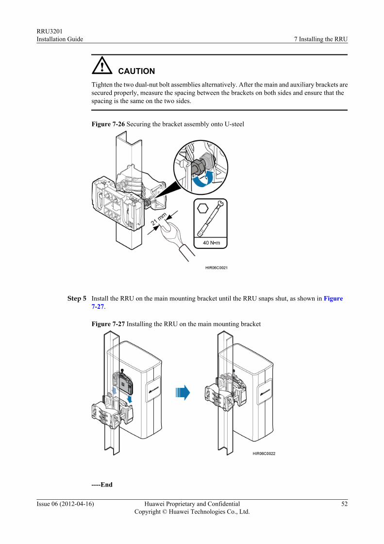
CAUTIONTighten the two dual-nut bolt assemblies alternatively. After the main and auxiliary brackets aresecured properly, measure the spacing between the brackets on both sides and ensure that thespacing is the same on the two sides.
Figure 7-26 Securing the bracket assembly onto U-steel
Step 5 Install the RRU on the main mounting bracket until the RRU snaps shut, as shown in Figure7-27.
Figure 7-27 Installing the RRU on the main mounting bracket
----End
RRU3201Installation Guide 7 Installing the RRU
Issue 06 (2012-04-16) Huawei Proprietary and ConfidentialCopyright © Huawei Technologies Co., Ltd.
52
7.4 Installing the RRU on Angle SteelThis section describes the procedure for installing the RRU on angle steel and the precautionsthat must be taken during the installation. The RRU installed on angle steel can be mounted toa tower or placed on the ground. It is recommended that only one RRU be installed on anglesteel.
PrerequisitesBefore you install an RRU on a tower, the RRU and mounting kits are hoisted onto the tower.For details, see 6.1 Hoisting an RRU onto a Tower.
The hoist clamp on the main mounting bracket is secured properly.
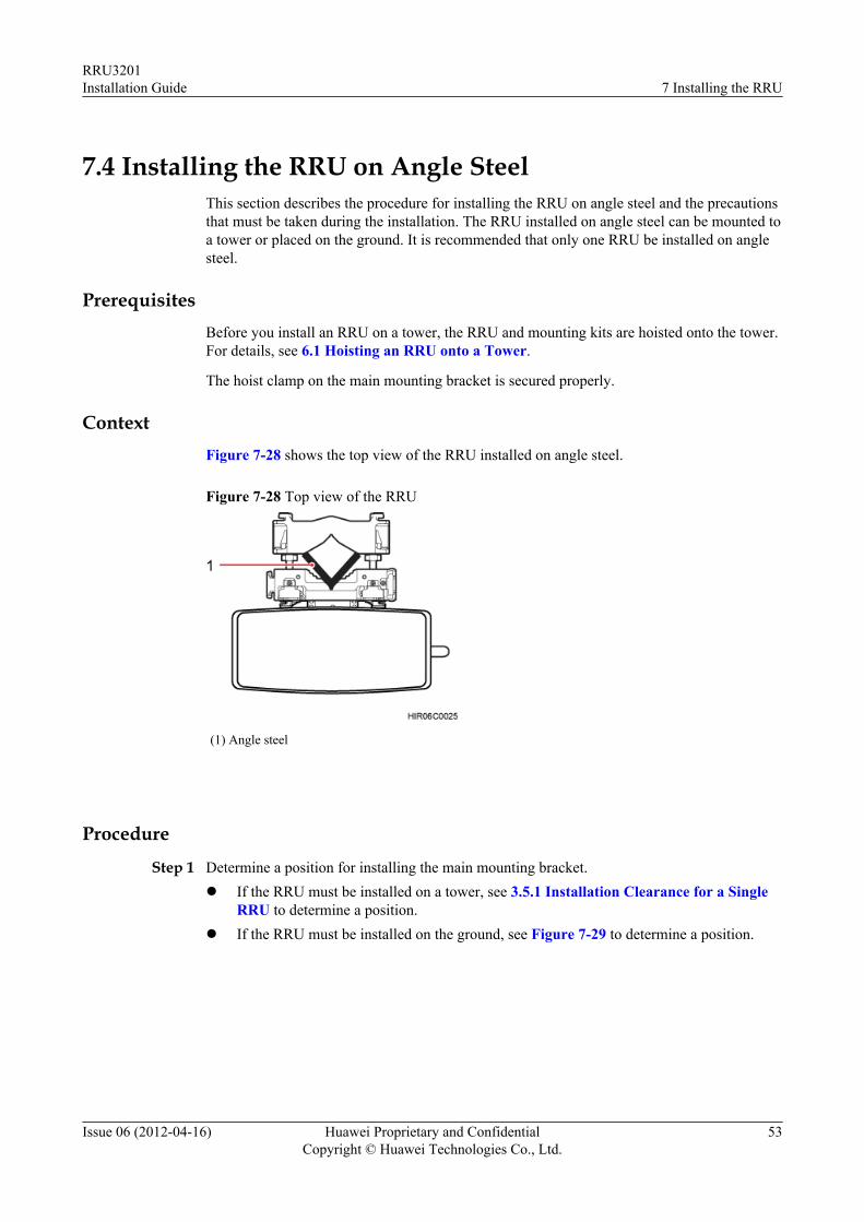
ContextFigure 7-28 shows the top view of the RRU installed on angle steel.
Figure 7-28 Top view of the RRU
(1) Angle steel
Procedure
Step 1 Determine a position for installing the main mounting bracket.l If the RRU must be installed on a tower, see 3.5.1 Installation Clearance for a Single
RRU to determine a position.l If the RRU must be installed on the ground, see Figure 7-29 to determine a position.
RRU3201Installation Guide 7 Installing the RRU
Issue 06 (2012-04-16) Huawei Proprietary and ConfidentialCopyright © Huawei Technologies Co., Ltd.
53
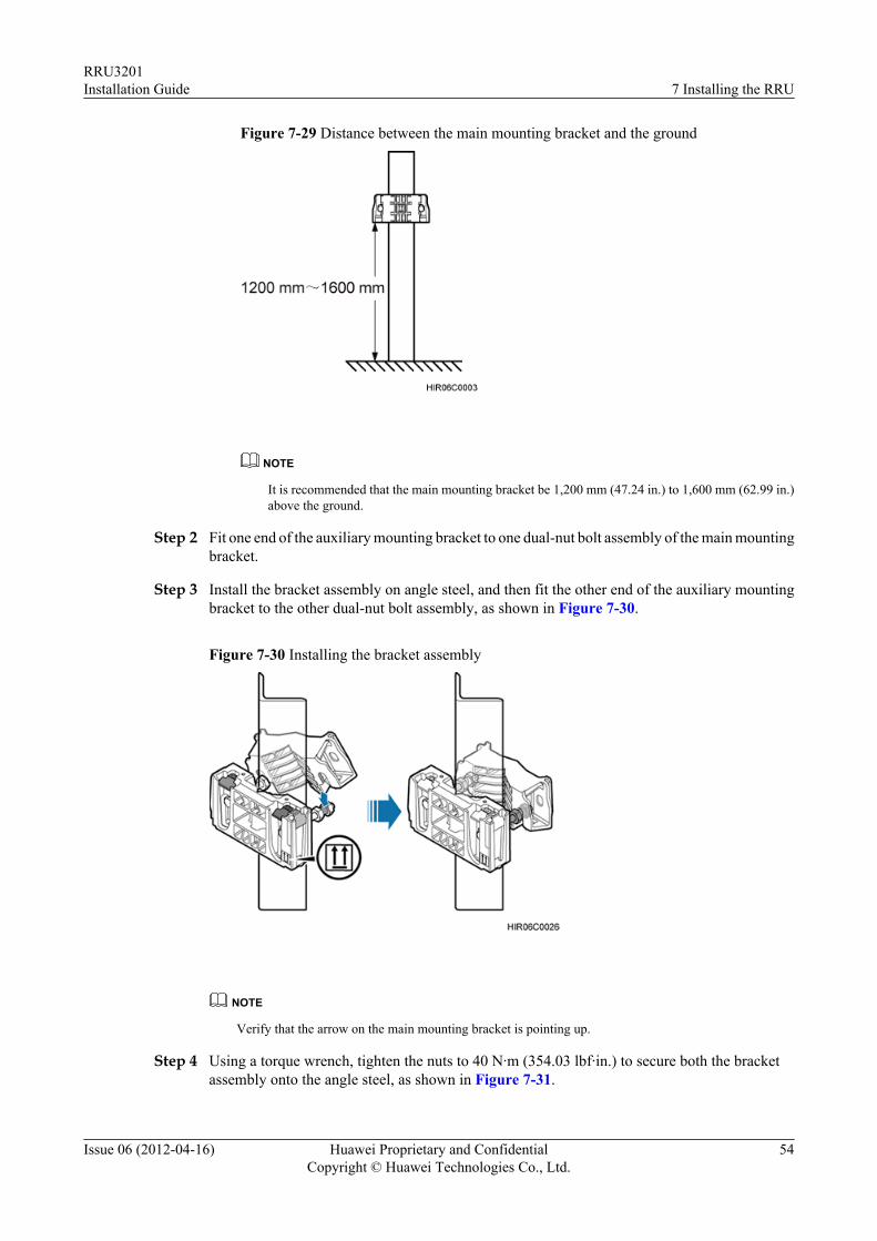
Figure 7-29 Distance between the main mounting bracket and the ground
NOTE
It is recommended that the main mounting bracket be 1,200 mm (47.24 in.) to 1,600 mm (62.99 in.)above the ground.
Step 2 Fit one end of the auxiliary mounting bracket to one dual-nut bolt assembly of the main mountingbracket.
Step 3 Install the bracket assembly on angle steel, and then fit the other end of the auxiliary mountingbracket to the other dual-nut bolt assembly, as shown in Figure 7-30.
Figure 7-30 Installing the bracket assembly
NOTE
Verify that the arrow on the main mounting bracket is pointing up.
Step 4 Using a torque wrench, tighten the nuts to 40 N·m (354.03 lbf·in.) to secure both the bracketassembly onto the angle steel, as shown in Figure 7-31.
RRU3201Installation Guide 7 Installing the RRU
Issue 06 (2012-04-16) Huawei Proprietary and ConfidentialCopyright © Huawei Technologies Co., Ltd.
54
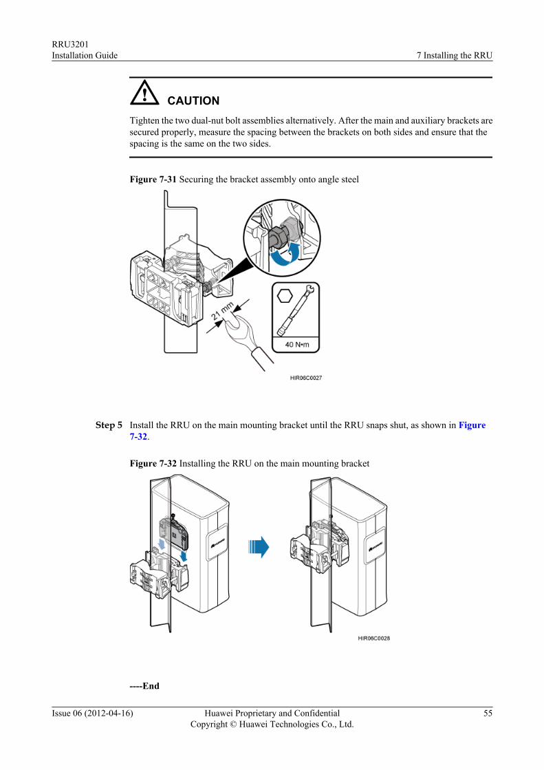
CAUTIONTighten the two dual-nut bolt assemblies alternatively. After the main and auxiliary brackets aresecured properly, measure the spacing between the brackets on both sides and ensure that thespacing is the same on the two sides.
Figure 7-31 Securing the bracket assembly onto angle steel
Step 5 Install the RRU on the main mounting bracket until the RRU snaps shut, as shown in Figure7-32.
Figure 7-32 Installing the RRU on the main mounting bracket
----End
RRU3201Installation Guide 7 Installing the RRU
Issue 06 (2012-04-16) Huawei Proprietary and ConfidentialCopyright © Huawei Technologies Co., Ltd.
55
7.5 Installing the RRU on a WallThis section describes the procedure for installing the RRU on a wall and the precautions thatmust be taken during the installation.
Prerequisites
The hoist clamp on the main mounting bracket is secured properly.
Context
The wall on which RRUs are installed must meet the following requirements:l When a single RRU is installed, the wall has a capacity of bearing at least four times the
weight of the RRU.l Expansion bolts must be tightened to 30 N·m (265.52 lbf·in.) to ensure the bolts work
properly and the wall remains intact without cracks in it.
Procedure
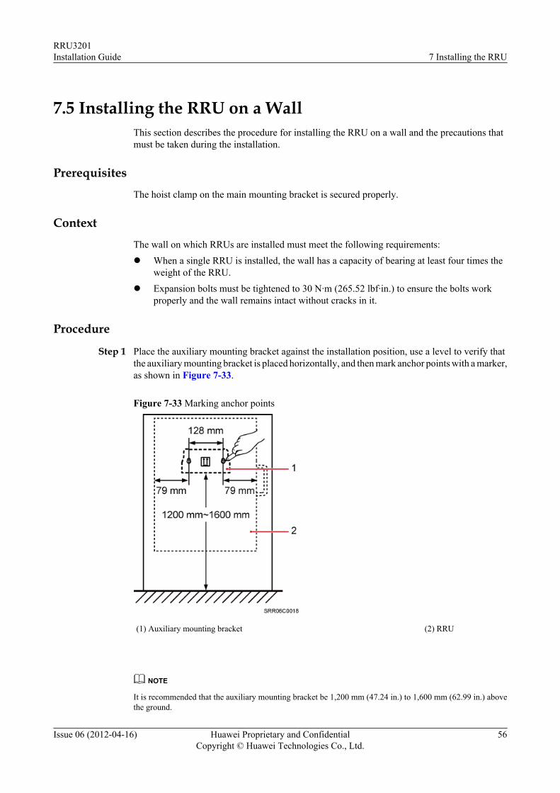
Step 1 Place the auxiliary mounting bracket against the installation position, use a level to verify thatthe auxiliary mounting bracket is placed horizontally, and then mark anchor points with a marker,as shown in Figure 7-33.
Figure 7-33 Marking anchor points
(1) Auxiliary mounting bracket (2) RRU
NOTE
It is recommended that the auxiliary mounting bracket be 1,200 mm (47.24 in.) to 1,600 mm (62.99 in.) abovethe ground.
RRU3201Installation Guide 7 Installing the RRU
Issue 06 (2012-04-16) Huawei Proprietary and ConfidentialCopyright © Huawei Technologies Co., Ltd.
56
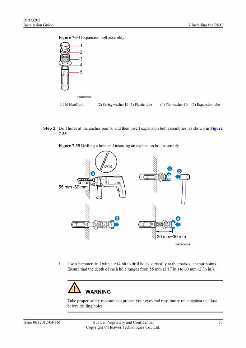
Figure 7-34 Expansion bolt assembly
(1) M10x65 bolt (2) Spring washer 10 (3) Plastic tube (4) Flat washer 10 (5) Expansion tube
Step 2 Drill holes at the anchor points, and then insert expansion bolt assemblies, as shown in Figure7-35.
Figure 7-35 Drilling a hole and inserting an expansion bolt assembly
1. Use a hammer drill with a φ14 bit to drill holes vertically at the marked anchor points.
Ensure that the depth of each hole ranges from 55 mm (2.17 in.) to 60 mm (2.36 in.).
WARNINGTake proper safety measures to protect your eyes and respiratory tract against the dustbefore drilling holes.
RRU3201Installation Guide 7 Installing the RRU
Issue 06 (2012-04-16) Huawei Proprietary and ConfidentialCopyright © Huawei Technologies Co., Ltd.
57
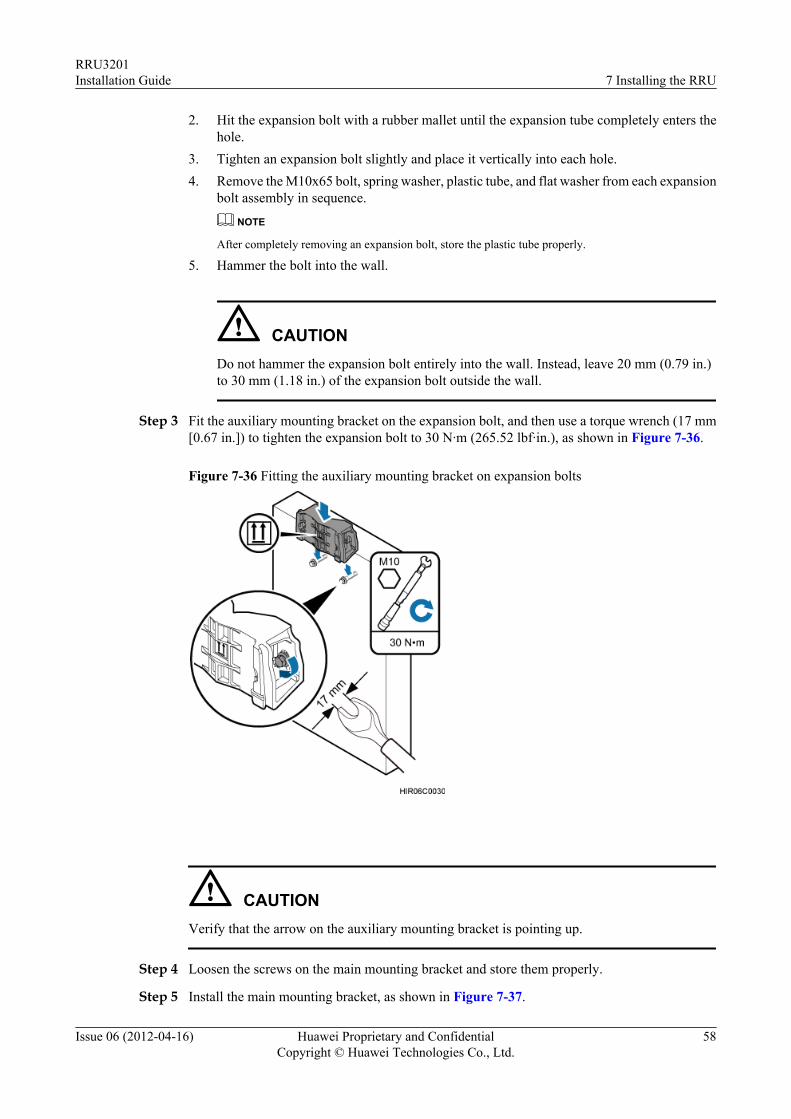
2. Hit the expansion bolt with a rubber mallet until the expansion tube completely enters thehole.
3. Tighten an expansion bolt slightly and place it vertically into each hole.4. Remove the M10x65 bolt, spring washer, plastic tube, and flat washer from each expansion
bolt assembly in sequence.
NOTE
After completely removing an expansion bolt, store the plastic tube properly.
5. Hammer the bolt into the wall.
CAUTIONDo not hammer the expansion bolt entirely into the wall. Instead, leave 20 mm (0.79 in.)to 30 mm (1.18 in.) of the expansion bolt outside the wall.
Step 3 Fit the auxiliary mounting bracket on the expansion bolt, and then use a torque wrench (17 mm[0.67 in.]) to tighten the expansion bolt to 30 N·m (265.52 lbf·in.), as shown in Figure 7-36.
Figure 7-36 Fitting the auxiliary mounting bracket on expansion bolts
CAUTIONVerify that the arrow on the auxiliary mounting bracket is pointing up.
Step 4 Loosen the screws on the main mounting bracket and store them properly.
Step 5 Install the main mounting bracket, as shown in Figure 7-37.
RRU3201Installation Guide 7 Installing the RRU
Issue 06 (2012-04-16) Huawei Proprietary and ConfidentialCopyright © Huawei Technologies Co., Ltd.
58
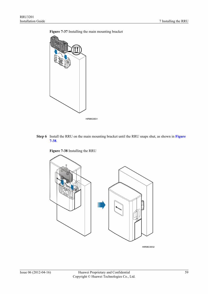
Figure 7-37 Installing the main mounting bracket
Step 6 Install the RRU on the main mounting bracket until the RRU snaps shut, as shown in Figure7-38.
Figure 7-38 Installing the RRU
RRU3201Installation Guide 7 Installing the RRU
Issue 06 (2012-04-16) Huawei Proprietary and ConfidentialCopyright © Huawei Technologies Co., Ltd.
59

----End
RRU3201Installation Guide 7 Installing the RRU
Issue 06 (2012-04-16) Huawei Proprietary and ConfidentialCopyright © Huawei Technologies Co., Ltd.
60
8 Installing RRU Cables
About This Chapter
This chapter describes the procedure for installing RRU cables.
8.1 Cabling RequirementsCables must be routed according to the specified cabling requirements to prevent signalinterference.
8.2 Cable ConnectionsThis section describes the cable connections for a single RRU and multiple RRUs.
8.3 Installation ProcessThis section describes the process of installing RRU cables.
8.4 RRU Cable ListThis section describes RRU cable connections.
8.5 Installing an RRU PGND CableThis section describes the procedure for installing an RRU PGND cable.
8.6 Installing an RRU RF JumperThis section describes the procedure for installing an RRU RF jumper.
8.7 Installing an RRU AISG Multi-Wire Cable and AISG Extension CableThis section describes the procedures for installing an RRU AISG multi-wire cable and AISGextension cable.
8.8 Opening the Cover Plate of an RRU Cabling CavityThis section describes the procedure for opening the cover plate of an RRU cabling cavity.
8.9 Installing an RRU power cableThis section describes the procedure for installing an RRU power cable.
8.10 Installing a CPRI Fiber Optic CableThis section describes the procedure for installing a CPRI fiber optic cable.
8.11 Closing the Cover Plate of an RRU Cabling CavityThis section describes the procedure for closing the cover plate of an RRU cabling cavity.
RRU3201Installation Guide 8 Installing RRU Cables
Issue 06 (2012-04-16) Huawei Proprietary and ConfidentialCopyright © Huawei Technologies Co., Ltd.
61
8.1 Cabling RequirementsCables must be routed according to the specified cabling requirements to prevent signalinterference.
NOTEIf a cable listed below is not required, skip the routing requirements of the cable.
General Cabling Requirements
Requirements for Bending Radiusl The bending radius of the 7/8'' feeder must be more than 250 mm (9.84 in.), and the bending
radius of the 5/4'' feeder must be more than 380 mm (14.96 in.).
l The bending radius of the 1/4'' jumper must be more than 35 mm (1.38 in.). The bendingradius of the super-flexible 1/2'' jumper must be more than 50 mm (1.97 in.), and the bendingradius of the ordinary 1/2'' jumper must be more than 127 mm (5 in.).
l The bending radius of the power cable or PGND cable must be at least three times thediameter of the cable.
l The bending radius of a fiber optic cable is at least 20 times the diameter of the fiber opticcable, and the minimum bending radius of the breakout cable at each end of the fiber opticcable is 30 mm (1.18 in.).
l The bending radius of the E1/T1 cable must be at least three times the diameter of the cable.
l The bending radius of the signal cable must be at least five times the diameter of the cable.
Requirements for Cable Bindingl The same types of cable must be bound together.
l Different types of cable must be separately routed with the minimum spacing of 30 mm(1.18 in.) and cannot be entangled.
l The cables must be bound tightly and neatly. The sheaths of the cables must not be damaged.
l Cable ties are installed in the same direction, and those at the same horizontal line must bein a straight line.
l The excess of indoor cable ties is trimmed off, and the excess of outdoor cable ties allowsabout 5 mm (0.2 in.), without remaining rough edges.
l Labels or nameplates must be attached to both ends, joints, or turns of cables after they areinstalled.
Security Requirementsl Cables should be placed away from sharp objects or wall burrs. If these positions are
inevitable, protect the cables with protection pipes.
l Cables must be routed away from heat sources, or heat-insulation materials are addedbetween cables and heat sources.
l Sufficient slack (recommended for about 0.1 m [0.33 ft.]) is provided in cables at turns orthe position close to a device, facilitating cable and device maintenance.
Indoor Cabling Requirementsl Cables are routed indoors through the feeder window.
RRU3201Installation Guide 8 Installing RRU Cables
Issue 06 (2012-04-16) Huawei Proprietary and ConfidentialCopyright © Huawei Technologies Co., Ltd.
62
l Drip loops must be made outside the feeder window, and the requirements for the minimumbending radius are met.
l When cables are routed indoors, engineers are required indoors for cooperation.l The feeder window must be waterproofed.
Outdoor Cabling Requirementsl Cables routed outdoors must be led through a pipe when they may be damaged.l AC power cables, transmission cables, and cables buried in the ground must be protected.l If cables at the cabinet bottom need to be routed through a pipe along the ground, lead the
pipe into the cabinet base for about 3 m (9.84 ft.) to 5 m (16.4 ft.), not into the cabinet.Block the pipe with waterproof tape or silicon gel, and secure the pipe to the cable hole atthe cabinet bottom with metal piece.
l If cables at the cabinet bottom need to be routed through a pipe along the metal cable trough,do not lead the pipe into the cabinet base. The cable trough must be sealed and routedthrough the cable hole at the cabinet bottom.
l Cables are secured with cable clips.l Cables are routed neatly along the specified cabling direction and secured with cable clips.l The positions for cable clips are determined onsite. For example, the cable clips for the
7/8" feeder are installed at the spacing of 1.5 m (4.92 ft.) to 2 m (6.56 ft.) in the samedirection, and the cable clips for the power cables are installed at the spacing of 1 m (3.28ft.) to 1.5 m (4.92 ft.) in the same direction.
l Cable clips must be vertical with cables, and the cables in a cable clip must be parallel.l After routing cables neatly and correctly, tighten the screws on cable clips.
Secure cables on the cable tray, as shown in Figure 8-1.
RRU3201Installation Guide 8 Installing RRU Cables
Issue 06 (2012-04-16) Huawei Proprietary and ConfidentialCopyright © Huawei Technologies Co., Ltd.
63
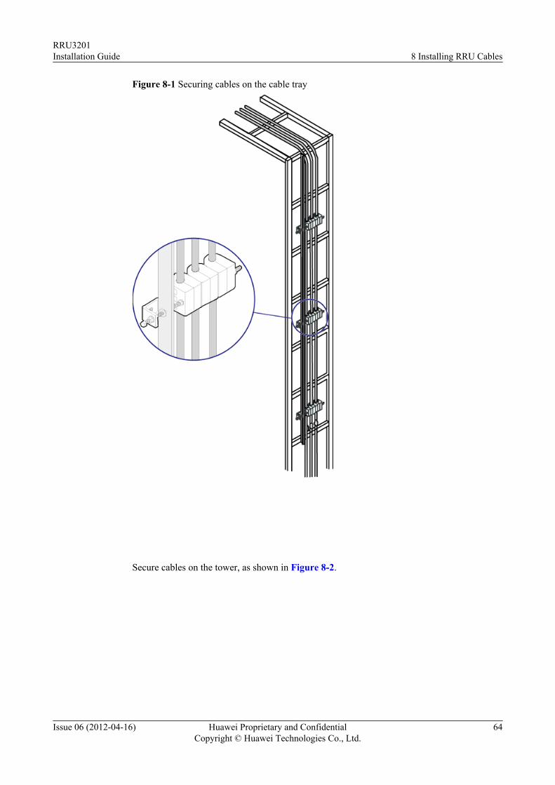
Figure 8-1 Securing cables on the cable tray
Secure cables on the tower, as shown in Figure 8-2.
RRU3201Installation Guide 8 Installing RRU Cables
Issue 06 (2012-04-16) Huawei Proprietary and ConfidentialCopyright © Huawei Technologies Co., Ltd.
64
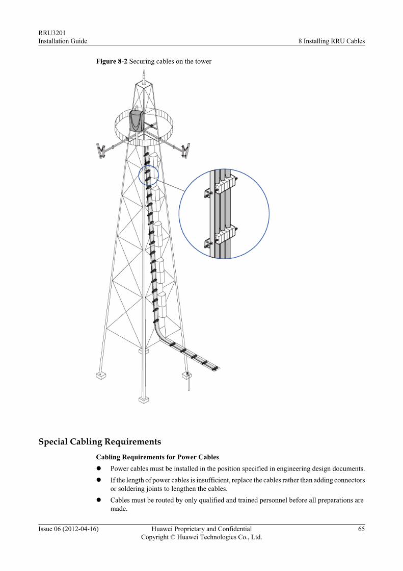
Figure 8-2 Securing cables on the tower
Special Cabling RequirementsCabling Requirements for Power Cablesl Power cables must be installed in the position specified in engineering design documents.l If the length of power cables is insufficient, replace the cables rather than adding connectors
or soldering joints to lengthen the cables.l Cables must be routed by only qualified and trained personnel before all preparations are
made.
RRU3201Installation Guide 8 Installing RRU Cables
Issue 06 (2012-04-16) Huawei Proprietary and ConfidentialCopyright © Huawei Technologies Co., Ltd.
65
l Cables are routed in an untangled and orderly fashion.l If DC power cables need to be routed on the tower platform, lay out the cables on the
guardrail with the shortest distance and route the cables along the guardrail.l If DC power cables need to be routed close to a device on the tower, secure the cables to
the guardrail or pole with cable clips. The device cannot be far away from the position forsecuring the cables.
Cabling Requirements for PGND Cablesl PGND cables for the base station must be connected to the same ground bar.l PGND cables must be buried in the ground or routed indoors. They should not be routed
overhead before they are led into the equipment room.l The exterior of the coaxial wire and the shield layer of the shielded cable must have proper
electrical contact with the metal surface of the equipment to which they are connected.l PGND cables and signal cables must be installed in an untangled and orderly fashion. A
certain distance must be reserved between them to prevent interference from each other.l Fuses or switches must not be installed on the PGND cables.l Other devices must not be used for electrical connections of the PGND cables.l All the metal parts in the housing of the equipment must be reliably connected to the ground
terminal.
Cabling Requirements for E1 Cablesl E1 cables must not cross power cables, PGND cables, or RF cables when routed. If
transmission cables are routed with power cables, PGND cables, or RF cables in parallel,the spacing between them must be greater than 30 mm (1.18 in.).
l E1 cables are routed straightly and bound neatly with cable ties.l Sufficient slack is provided in E1 cables at turns.
Cabling Requirements for Fiber Optic Cablesl Fiber optic cables must be routed by at least three qualified and trained personnel before
all preparations are made.l Fiber optic cables are used within the temperature range of -40°C to 60°C. If the current
temperature is out of the range, make protection measures or route the cables again.l Cables are routed in an untangled and orderly fashion.l Do not bind fiber optic cables at turns.l Do not stretch, step on, or place heavy objects on fiber optic cables. Keep the cables away
from sharp objects.l When fiber optic cables are routed, the excess of the cables must be coiled around special
devices, such as a fiber coiler.l When coiling fiber optic cables, apply even strength. Do not bend the cables with force.l Vacant optical connectors must be covered with dustproof caps.l Fiber optic cables cannot be squeezed by the cabinet door when routed through the cabinet.l If fiber optic cables need to be routed on the tower platform, lay out the cables on the
guardrail with the shortest distance and route the cables along the guardrail.l If fiber optic cables need to be routed close to a device on the tower, secure the cables to
the guardrail or pole with cable clips. The device cannot be far away from the position forsecuring the cables.
RRU3201Installation Guide 8 Installing RRU Cables
Issue 06 (2012-04-16) Huawei Proprietary and ConfidentialCopyright © Huawei Technologies Co., Ltd.
66
l If the fiber optic cables close to a device are too long, coil the excess of the cables andsecure them on the tower.
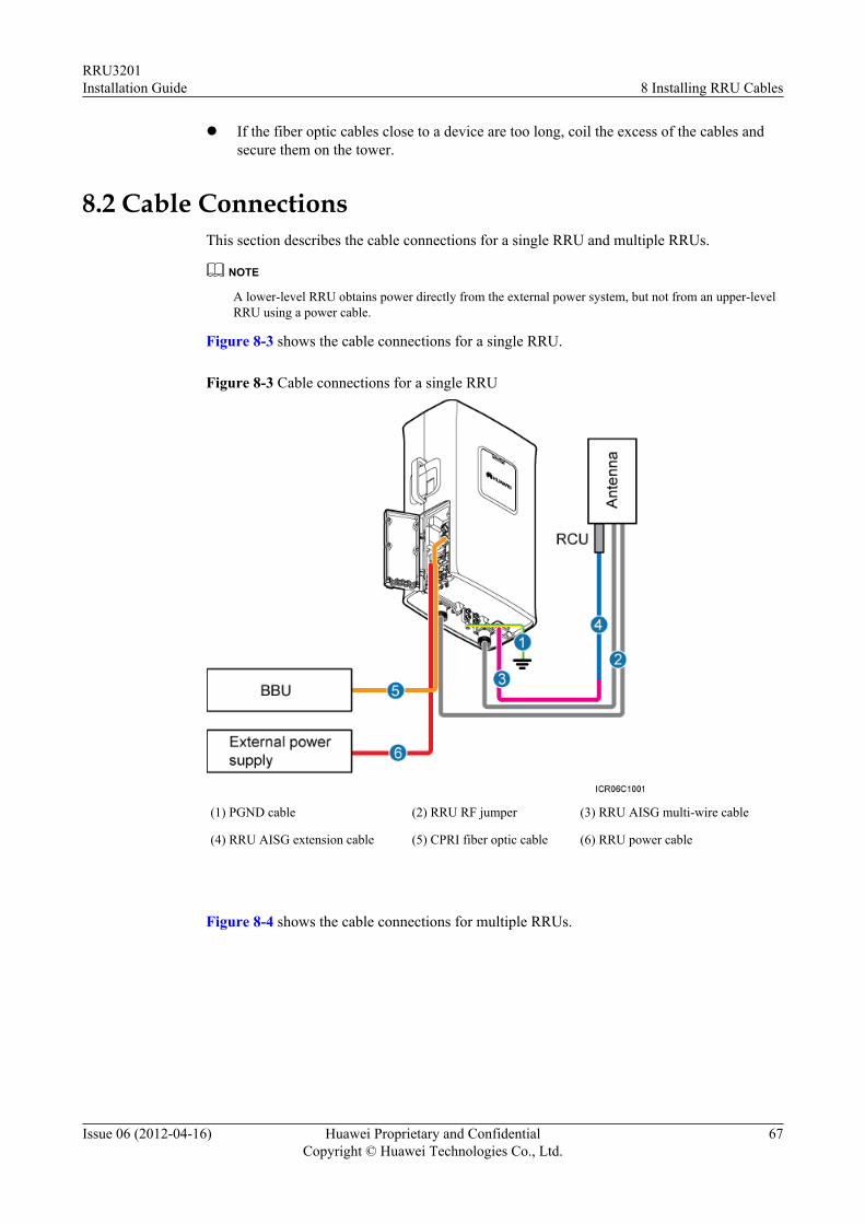
8.2 Cable ConnectionsThis section describes the cable connections for a single RRU and multiple RRUs.
NOTE
A lower-level RRU obtains power directly from the external power system, but not from an upper-levelRRU using a power cable.
Figure 8-3 shows the cable connections for a single RRU.
Figure 8-3 Cable connections for a single RRU
(1) PGND cable (2) RRU RF jumper (3) RRU AISG multi-wire cable
(4) RRU AISG extension cable (5) CPRI fiber optic cable (6) RRU power cable
Figure 8-4 shows the cable connections for multiple RRUs.
RRU3201Installation Guide 8 Installing RRU Cables
Issue 06 (2012-04-16) Huawei Proprietary and ConfidentialCopyright © Huawei Technologies Co., Ltd.
67
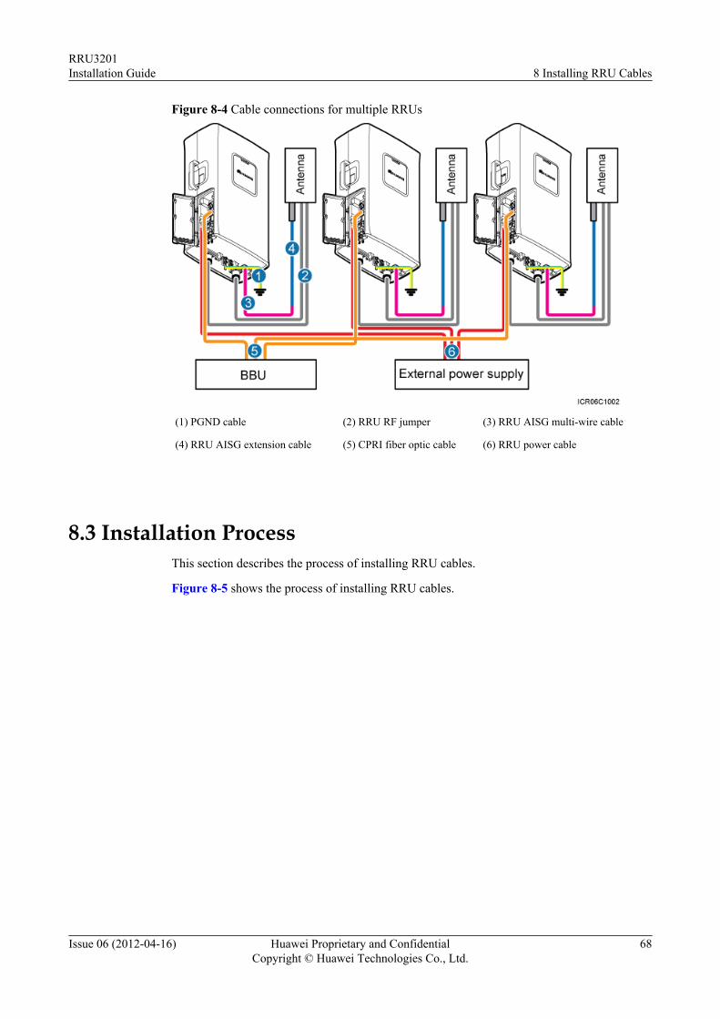
Figure 8-4 Cable connections for multiple RRUs
(1) PGND cable (2) RRU RF jumper (3) RRU AISG multi-wire cable
(4) RRU AISG extension cable (5) CPRI fiber optic cable (6) RRU power cable
8.3 Installation ProcessThis section describes the process of installing RRU cables.
Figure 8-5 shows the process of installing RRU cables.
RRU3201Installation Guide 8 Installing RRU Cables
Issue 06 (2012-04-16) Huawei Proprietary and ConfidentialCopyright © Huawei Technologies Co., Ltd.
68
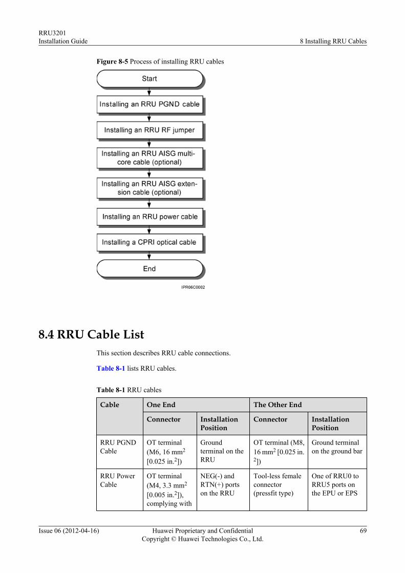
Figure 8-5 Process of installing RRU cables
8.4 RRU Cable ListThis section describes RRU cable connections.
Table 8-1 lists RRU cables.
Table 8-1 RRU cables
Cable One End The Other End
Connector InstallationPosition
Connector InstallationPosition
RRU PGNDCable
OT terminal(M6, 16 mm2
[0.025 in.2])
Groundterminal on theRRU
OT terminal (M8,16 mm2 [0.025 in.2])
Ground terminalon the ground bar
RRU PowerCable
OT terminal(M4, 3.3 mm2
[0.005 in.2]),complying with
NEG(-) andRTN(+) portson the RRU
Tool-less femaleconnector(pressfit type)
One of RRU0 toRRU5 ports onthe EPU or EPS
RRU3201Installation Guide 8 Installing RRU Cables
Issue 06 (2012-04-16) Huawei Proprietary and ConfidentialCopyright © Huawei Technologies Co., Ltd.
69
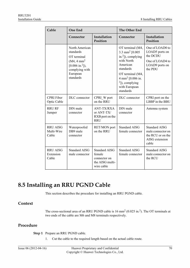
Cable One End The Other End
Connector InstallationPosition
Connector InstallationPosition
North AmericanstandardsOT terminal(M4, 4 mm2
[0.006 in.2]),complying withEuropeanstandards
OT terminal (M4,3.3 mm2 [0.005in.2]), complyingwith NorthAmericanstandardsOT terminal (M4,4 mm2 [0.006 in.2]), complyingwith Europeanstandards
One of LOAD0 toLOAD5 ports onthe DCDUOne of LOAD4 toLOAD9 ports onthe PDU
CPRI FiberOptic Cable
DLC connector CPRI_W porton the RRU
DLC connector CPRI port on theLBBP in the BBU
RRU RFJumper
DIN maleconnector
ANT-TX/RXAor ANT-TX/RXB port on theRRU
DIN maleconnector
Antenna system
RRU AISGMulti-WireCable
WaterproofedDB9 maleconnector
RET/MON porton the RRU
Standard AISGfemale connector
Standard AISGmale connector onthe RCU or on theAISG extensioncable
RRU AISGExtensionCable
Standard AISGmale connector
Standard AISGfemaleconnector onthe AISG multi-wire cable
Standard AISGfemale connector
Standard AISGmale connector onthe RCU
8.5 Installing an RRU PGND CableThis section describes the procedure for installing an RRU PGND cable.
Context
The cross-sectional area of an RRU PGND cable is 16 mm2 (0.025 in.2). The OT terminals attwo ends of the cable are M6 and M8 terminals respectively.
Procedure
Step 1 Prepare an RRU PGND cable.
1. Cut the cable to the required length based on the actual cable route.
RRU3201Installation Guide 8 Installing RRU Cables
Issue 06 (2012-04-16) Huawei Proprietary and ConfidentialCopyright © Huawei Technologies Co., Ltd.
70
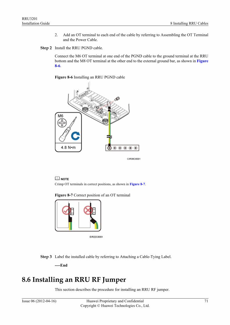
2. Add an OT terminal to each end of the cable by referring to Assembling the OT Terminaland the Power Cable.
Step 2 Install the RRU PGND cable.
Connect the M6 OT terminal at one end of the PGND cable to the ground terminal at the RRUbottom and the M8 OT terminal at the other end to the external ground bar, as shown in Figure8-6.
Figure 8-6 Installing an RRU PGND cable
NOTECrimp OT terminals in correct positions, as shown in Figure 8-7.
Figure 8-7 Correct position of an OT terminal
Step 3 Label the installed cable by referring to Attaching a Cable-Tying Label.
----End
8.6 Installing an RRU RF JumperThis section describes the procedure for installing an RRU RF jumper.
RRU3201Installation Guide 8 Installing RRU Cables
Issue 06 (2012-04-16) Huawei Proprietary and ConfidentialCopyright © Huawei Technologies Co., Ltd.
71
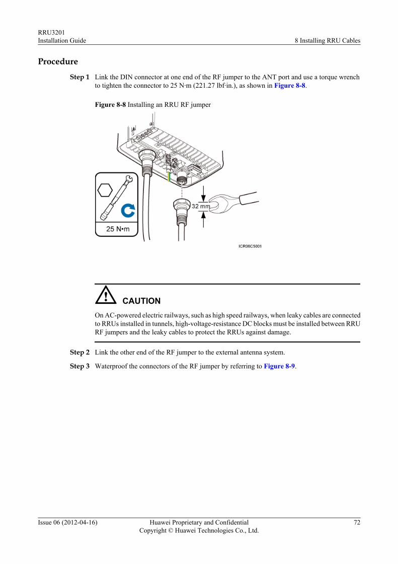
Procedure
Step 1 Link the DIN connector at one end of the RF jumper to the ANT port and use a torque wrenchto tighten the connector to 25 N·m (221.27 lbf·in.), as shown in Figure 8-8.
Figure 8-8 Installing an RRU RF jumper
CAUTIONOn AC-powered electric railways, such as high speed railways, when leaky cables are connectedto RRUs installed in tunnels, high-voltage-resistance DC blocks must be installed between RRURF jumpers and the leaky cables to protect the RRUs against damage.
Step 2 Link the other end of the RF jumper to the external antenna system.
Step 3 Waterproof the connectors of the RF jumper by referring to Figure 8-9.
RRU3201Installation Guide 8 Installing RRU Cables
Issue 06 (2012-04-16) Huawei Proprietary and ConfidentialCopyright © Huawei Technologies Co., Ltd.
72
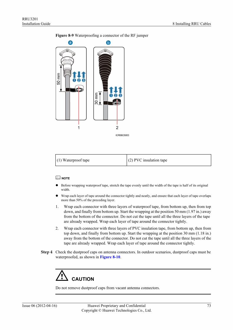
Figure 8-9 Waterproofing a connector of the RF jumper
(1) Waterproof tape (2) PVC insulation tape
NOTE
l Before wrapping waterproof tape, stretch the tape evenly until the width of the tape is half of its originalwidth.
l Wrap each layer of tape around the connector tightly and neatly, and ensure that each layer of tape overlapsmore than 50% of the preceding layer.
1. Wrap each connector with three layers of waterproof tape, from bottom up, then from topdown, and finally from bottom up. Start the wrapping at the position 50 mm (1.97 in.) awayfrom the bottom of the connector. Do not cut the tape until all the three layers of the tapeare already wrapped. Wrap each layer of tape around the connector tightly.
2. Wrap each connector with three layers of PVC insulation tape, from bottom up, then fromtop down, and finally from bottom up. Start the wrapping at the position 30 mm (1.18 in.)away from the bottom of the connector. Do not cut the tape until all the three layers of thetape are already wrapped. Wrap each layer of tape around the connector tightly.
Step 4 Check the dustproof caps on antenna connectors. In outdoor scenarios, dustproof caps must bewaterproofed, as shown in Figure 8-10.
CAUTIONDo not remove dustproof caps from vacant antenna connectors.
RRU3201Installation Guide 8 Installing RRU Cables
Issue 06 (2012-04-16) Huawei Proprietary and ConfidentialCopyright © Huawei Technologies Co., Ltd.
73
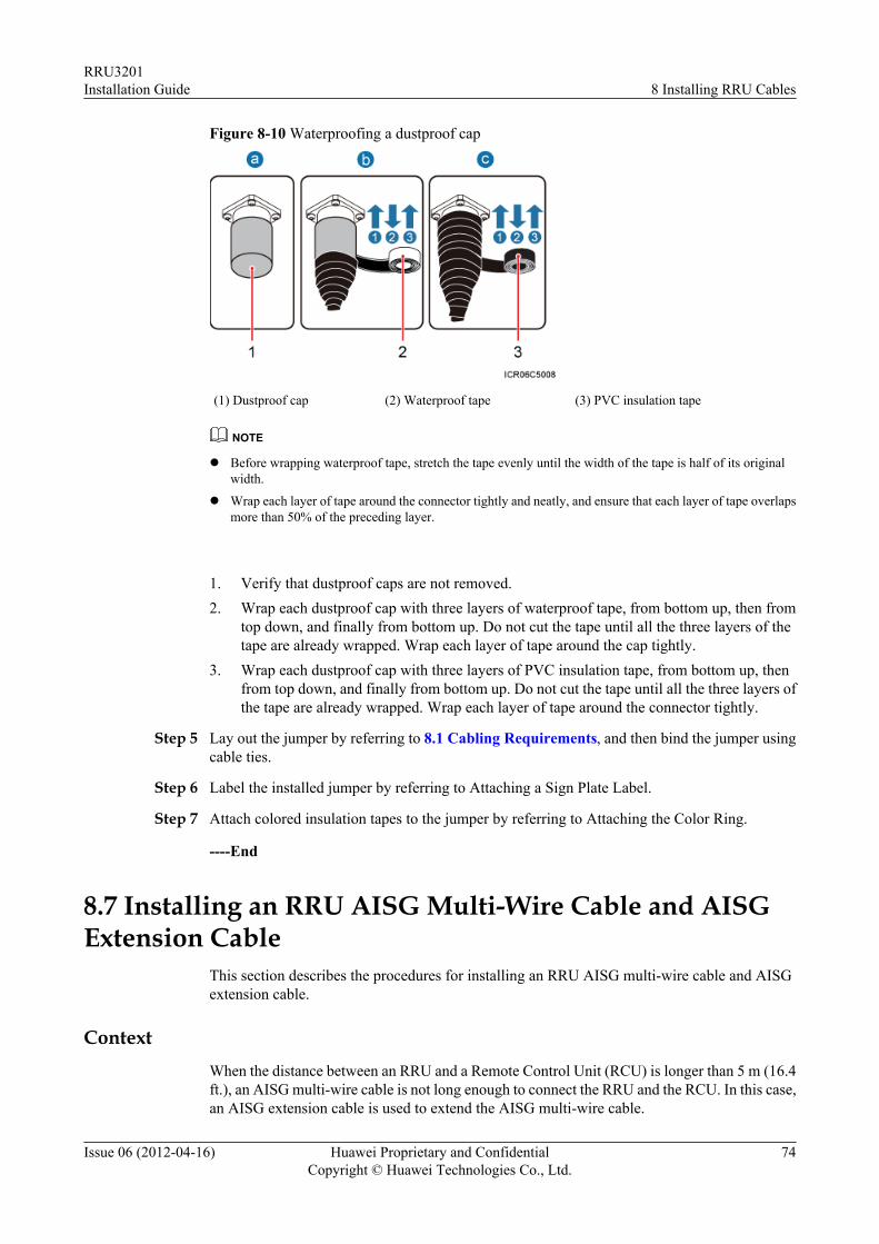
Figure 8-10 Waterproofing a dustproof cap
(1) Dustproof cap (2) Waterproof tape (3) PVC insulation tape
NOTE
l Before wrapping waterproof tape, stretch the tape evenly until the width of the tape is half of its originalwidth.
l Wrap each layer of tape around the connector tightly and neatly, and ensure that each layer of tape overlapsmore than 50% of the preceding layer.
1. Verify that dustproof caps are not removed.2. Wrap each dustproof cap with three layers of waterproof tape, from bottom up, then from
top down, and finally from bottom up. Do not cut the tape until all the three layers of thetape are already wrapped. Wrap each layer of tape around the cap tightly.
3. Wrap each dustproof cap with three layers of PVC insulation tape, from bottom up, thenfrom top down, and finally from bottom up. Do not cut the tape until all the three layers ofthe tape are already wrapped. Wrap each layer of tape around the connector tightly.
Step 5 Lay out the jumper by referring to 8.1 Cabling Requirements, and then bind the jumper usingcable ties.
Step 6 Label the installed jumper by referring to Attaching a Sign Plate Label.
Step 7 Attach colored insulation tapes to the jumper by referring to Attaching the Color Ring.
----End
8.7 Installing an RRU AISG Multi-Wire Cable and AISGExtension Cable
This section describes the procedures for installing an RRU AISG multi-wire cable and AISGextension cable.
ContextWhen the distance between an RRU and a Remote Control Unit (RCU) is longer than 5 m (16.4ft.), an AISG multi-wire cable is not long enough to connect the RRU and the RCU. In this case,an AISG extension cable is used to extend the AISG multi-wire cable.
RRU3201Installation Guide 8 Installing RRU Cables
Issue 06 (2012-04-16) Huawei Proprietary and ConfidentialCopyright © Huawei Technologies Co., Ltd.
74
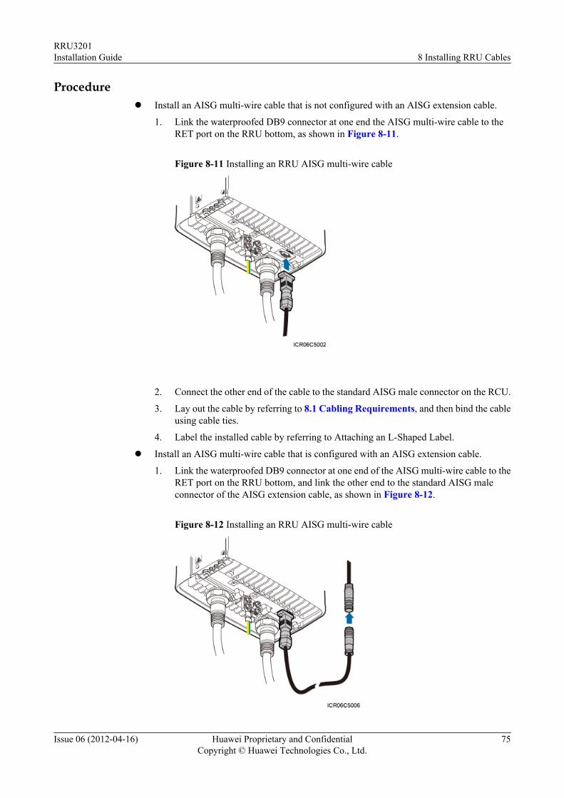
Procedurel Install an AISG multi-wire cable that is not configured with an AISG extension cable.
1. Link the waterproofed DB9 connector at one end the AISG multi-wire cable to theRET port on the RRU bottom, as shown in Figure 8-11.
Figure 8-11 Installing an RRU AISG multi-wire cable
2. Connect the other end of the cable to the standard AISG male connector on the RCU.
3. Lay out the cable by referring to 8.1 Cabling Requirements, and then bind the cableusing cable ties.
4. Label the installed cable by referring to Attaching an L-Shaped Label.
l Install an AISG multi-wire cable that is configured with an AISG extension cable.
1. Link the waterproofed DB9 connector at one end of the AISG multi-wire cable to theRET port on the RRU bottom, and link the other end to the standard AISG maleconnector of the AISG extension cable, as shown in Figure 8-12.
Figure 8-12 Installing an RRU AISG multi-wire cable
RRU3201Installation Guide 8 Installing RRU Cables
Issue 06 (2012-04-16) Huawei Proprietary and ConfidentialCopyright © Huawei Technologies Co., Ltd.
75

2. Connect the other end of the AISG extension cable to the standard AISG male
connector on the RCU, as shown in Figure 8-13.
Figure 8-13 Installing an RRU AISG extension cable
3. Lay out the cable by referring to 8.1 Cabling Requirements, and then bind the cable
using cable ties.4. Label the installed cable by referring to Attaching an L-Shaped Label.
----End
8.8 Opening the Cover Plate of an RRU Cabling CavityThis section describes the procedure for opening the cover plate of an RRU cabling cavity.
Procedure
Step 1 Wear ESD gloves.
CAUTIONTake proper ESD protection measures, for example, wear ESD gloves, to prevent electrostaticdamage to the boards, modules, or electronic components.
Step 2 Loosen the six screws on the cover plate of the RRU cabling cavity using an M4 Phillipsscrewdriver, and then open the cover plate, as shown in Figure 8-14.
RRU3201Installation Guide 8 Installing RRU Cables
Issue 06 (2012-04-16) Huawei Proprietary and ConfidentialCopyright © Huawei Technologies Co., Ltd.
76
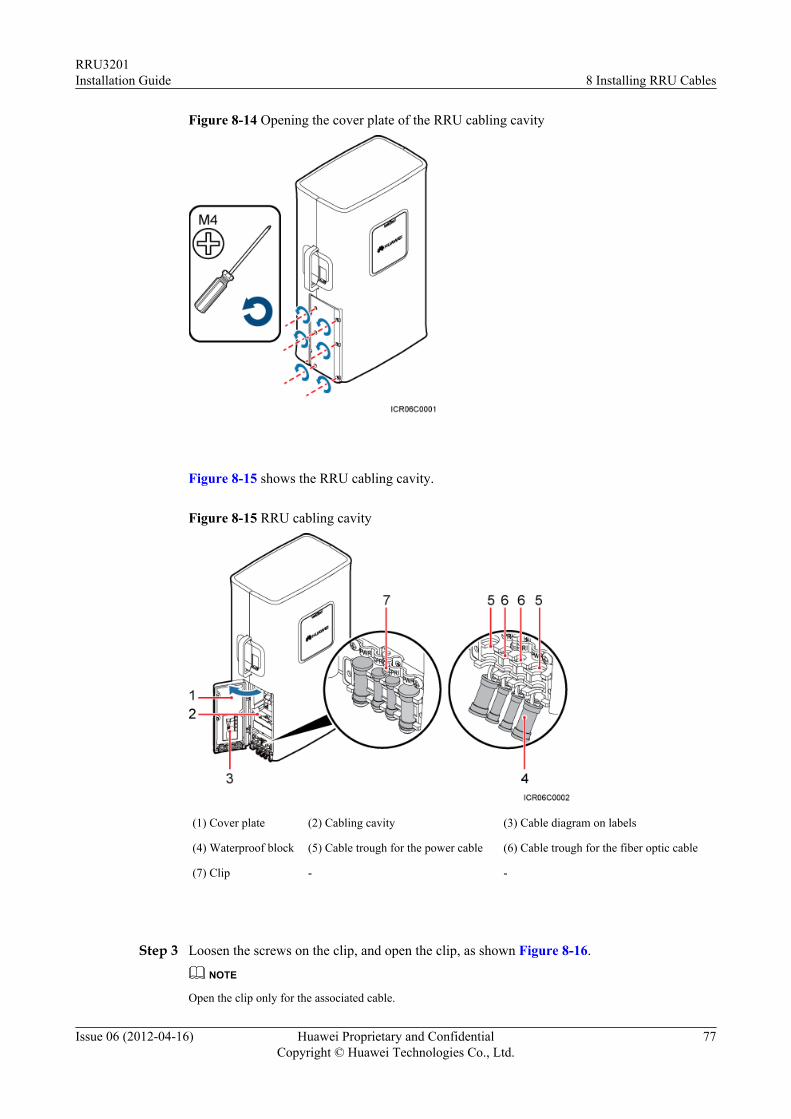
Figure 8-14 Opening the cover plate of the RRU cabling cavity
Figure 8-15 shows the RRU cabling cavity.
Figure 8-15 RRU cabling cavity
(1) Cover plate (2) Cabling cavity (3) Cable diagram on labels
(4) Waterproof block (5) Cable trough for the power cable (6) Cable trough for the fiber optic cable
(7) Clip - -
Step 3 Loosen the screws on the clip, and open the clip, as shown Figure 8-16.
NOTE
Open the clip only for the associated cable.
RRU3201Installation Guide 8 Installing RRU Cables
Issue 06 (2012-04-16) Huawei Proprietary and ConfidentialCopyright © Huawei Technologies Co., Ltd.
77
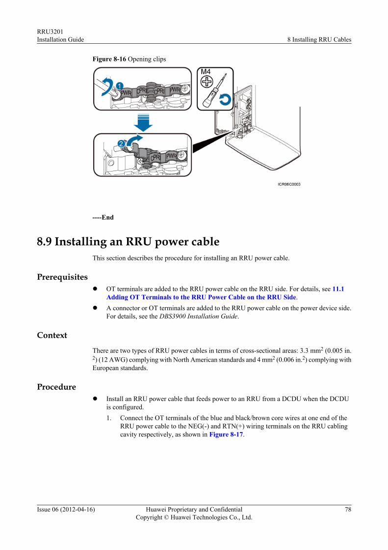
Figure 8-16 Opening clips
----End
8.9 Installing an RRU power cableThis section describes the procedure for installing an RRU power cable.
Prerequisitesl OT terminals are added to the RRU power cable on the RRU side. For details, see 11.1
Adding OT Terminals to the RRU Power Cable on the RRU Side.l A connector or OT terminals are added to the RRU power cable on the power device side.
For details, see the DBS3900 Installation Guide.
Context
There are two types of RRU power cables in terms of cross-sectional areas: 3.3 mm2 (0.005 in.2) (12 AWG) complying with North American standards and 4 mm2 (0.006 in.2) complying withEuropean standards.
Procedurel Install an RRU power cable that feeds power to an RRU from a DCDU when the DCDU
is configured.1. Connect the OT terminals of the blue and black/brown core wires at one end of the
RRU power cable to the NEG(-) and RTN(+) wiring terminals on the RRU cablingcavity respectively, as shown in Figure 8-17.
RRU3201Installation Guide 8 Installing RRU Cables
Issue 06 (2012-04-16) Huawei Proprietary and ConfidentialCopyright © Huawei Technologies Co., Ltd.
78
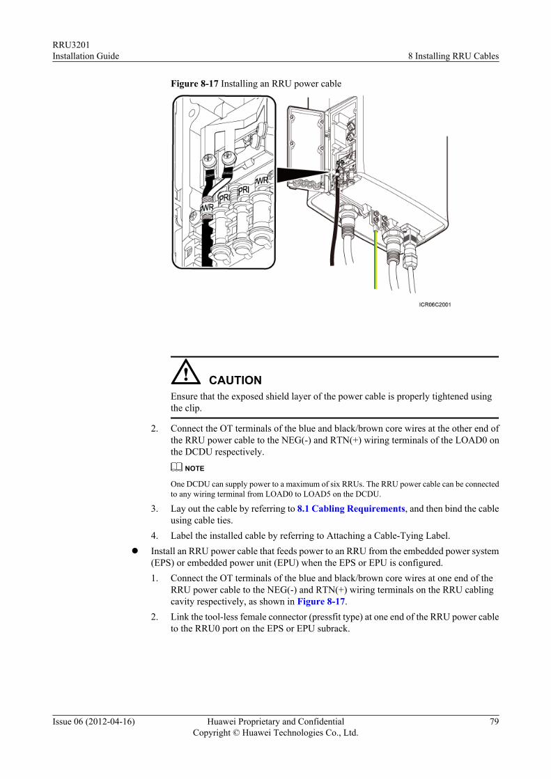
Figure 8-17 Installing an RRU power cable
CAUTIONEnsure that the exposed shield layer of the power cable is properly tightened usingthe clip.
2. Connect the OT terminals of the blue and black/brown core wires at the other end ofthe RRU power cable to the NEG(-) and RTN(+) wiring terminals of the LOAD0 onthe DCDU respectively.
NOTE
One DCDU can supply power to a maximum of six RRUs. The RRU power cable can be connectedto any wiring terminal from LOAD0 to LOAD5 on the DCDU.
3. Lay out the cable by referring to 8.1 Cabling Requirements, and then bind the cableusing cable ties.
4. Label the installed cable by referring to Attaching a Cable-Tying Label.l Install an RRU power cable that feeds power to an RRU from the embedded power system
(EPS) or embedded power unit (EPU) when the EPS or EPU is configured.1. Connect the OT terminals of the blue and black/brown core wires at one end of the
RRU power cable to the NEG(-) and RTN(+) wiring terminals on the RRU cablingcavity respectively, as shown in Figure 8-17.
2. Link the tool-less female connector (pressfit type) at one end of the RRU power cableto the RRU0 port on the EPS or EPU subrack.
RRU3201Installation Guide 8 Installing RRU Cables
Issue 06 (2012-04-16) Huawei Proprietary and ConfidentialCopyright © Huawei Technologies Co., Ltd.
79
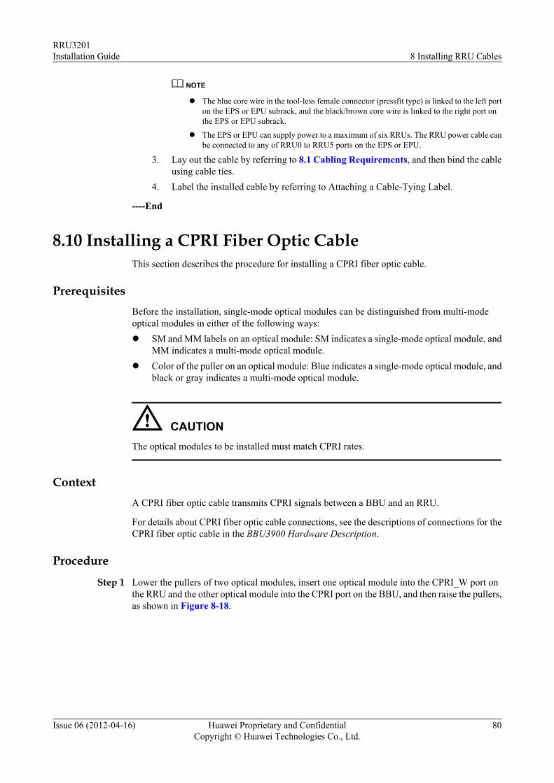
NOTE
l The blue core wire in the tool-less female connector (pressfit type) is linked to the left porton the EPS or EPU subrack, and the black/brown core wire is linked to the right port onthe EPS or EPU subrack.
l The EPS or EPU can supply power to a maximum of six RRUs. The RRU power cable canbe connected to any of RRU0 to RRU5 ports on the EPS or EPU.
3. Lay out the cable by referring to 8.1 Cabling Requirements, and then bind the cableusing cable ties.
4. Label the installed cable by referring to Attaching a Cable-Tying Label.
----End
8.10 Installing a CPRI Fiber Optic CableThis section describes the procedure for installing a CPRI fiber optic cable.
PrerequisitesBefore the installation, single-mode optical modules can be distinguished from multi-modeoptical modules in either of the following ways:l SM and MM labels on an optical module: SM indicates a single-mode optical module, and
MM indicates a multi-mode optical module.l Color of the puller on an optical module: Blue indicates a single-mode optical module, and
black or gray indicates a multi-mode optical module.
CAUTIONThe optical modules to be installed must match CPRI rates.
ContextA CPRI fiber optic cable transmits CPRI signals between a BBU and an RRU.
For details about CPRI fiber optic cable connections, see the descriptions of connections for theCPRI fiber optic cable in the BBU3900 Hardware Description.
Procedure
Step 1 Lower the pullers of two optical modules, insert one optical module into the CPRI_W port onthe RRU and the other optical module into the CPRI port on the BBU, and then raise the pullers,as shown in Figure 8-18.
RRU3201Installation Guide 8 Installing RRU Cables
Issue 06 (2012-04-16) Huawei Proprietary and ConfidentialCopyright © Huawei Technologies Co., Ltd.
80
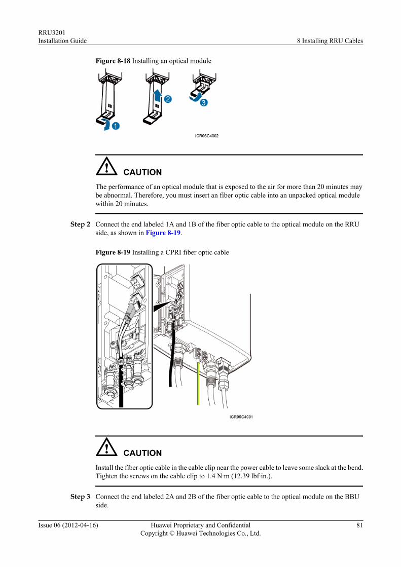
Figure 8-18 Installing an optical module
CAUTIONThe performance of an optical module that is exposed to the air for more than 20 minutes maybe abnormal. Therefore, you must insert an fiber optic cable into an unpacked optical modulewithin 20 minutes.
Step 2 Connect the end labeled 1A and 1B of the fiber optic cable to the optical module on the RRUside, as shown in Figure 8-19.
Figure 8-19 Installing a CPRI fiber optic cable
CAUTIONInstall the fiber optic cable in the cable clip near the power cable to leave some slack at the bend.Tighten the screws on the cable clip to 1.4 N·m (12.39 lbf·in.).
Step 3 Connect the end labeled 2A and 2B of the fiber optic cable to the optical module on the BBUside.
RRU3201Installation Guide 8 Installing RRU Cables
Issue 06 (2012-04-16) Huawei Proprietary and ConfidentialCopyright © Huawei Technologies Co., Ltd.
81
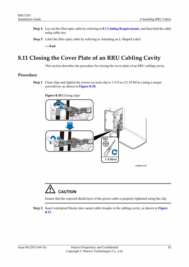
Step 4 Lay out the fiber optic cable by referring to 8.1 Cabling Requirements, and then bind the cableusing cable ties.
Step 5 Label the fiber optic cable by referring to Attaching an L-Shaped Label.
----End
8.11 Closing the Cover Plate of an RRU Cabling CavityThis section describes the procedure for closing the cover plate of an RRU cabling cavity.
Procedure
Step 1 Close clips and tighten the screws on each clip to 1.4 N·m (12.39 lbf·in.) using a torquescrewdriver, as shown in Figure 8-20.
Figure 8-20 Closing clips
CAUTIONEnsure that the exposed shield layer of the power cable is properly tightened using the clip.
Step 2 Insert waterproof blocks into vacant cable troughs in the cabling cavity, as shown in Figure8-21.
RRU3201Installation Guide 8 Installing RRU Cables
Issue 06 (2012-04-16) Huawei Proprietary and ConfidentialCopyright © Huawei Technologies Co., Ltd.
82
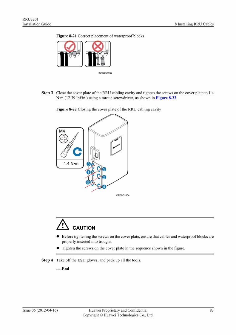
Figure 8-21 Correct placement of waterproof blocks
Step 3 Close the cover plate of the RRU cabling cavity and tighten the screws on the cover plate to 1.4N·m (12.39 lbf·in.) using a torque screwdriver, as shown in Figure 8-22.
Figure 8-22 Closing the cover plate of the RRU cabling cavity
CAUTIONl Before tightening the screws on the cover plate, ensure that cables and waterproof blocks are
properly inserted into troughs.l Tighten the screws on the cover plate in the sequence shown in the figure.
Step 4 Take off the ESD gloves, and pack up all the tools.
----End
RRU3201Installation Guide 8 Installing RRU Cables
Issue 06 (2012-04-16) Huawei Proprietary and ConfidentialCopyright © Huawei Technologies Co., Ltd.
83
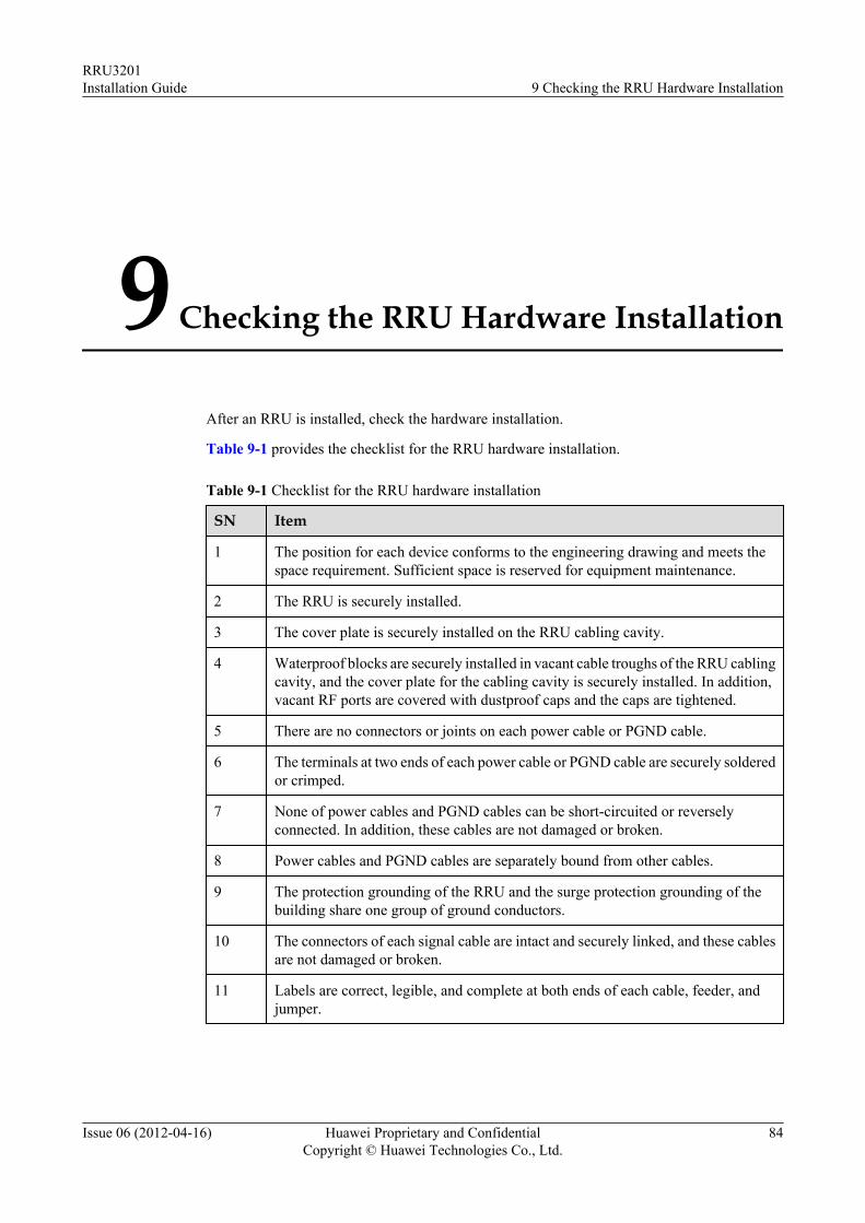
9 Checking the RRU Hardware Installation
After an RRU is installed, check the hardware installation.
Table 9-1 provides the checklist for the RRU hardware installation.
Table 9-1 Checklist for the RRU hardware installation
SN Item
1 The position for each device conforms to the engineering drawing and meets thespace requirement. Sufficient space is reserved for equipment maintenance.
2 The RRU is securely installed.
3 The cover plate is securely installed on the RRU cabling cavity.
4 Waterproof blocks are securely installed in vacant cable troughs of the RRU cablingcavity, and the cover plate for the cabling cavity is securely installed. In addition,vacant RF ports are covered with dustproof caps and the caps are tightened.
5 There are no connectors or joints on each power cable or PGND cable.
6 The terminals at two ends of each power cable or PGND cable are securely solderedor crimped.
7 None of power cables and PGND cables can be short-circuited or reverselyconnected. In addition, these cables are not damaged or broken.
8 Power cables and PGND cables are separately bound from other cables.
9 The protection grounding of the RRU and the surge protection grounding of thebuilding share one group of ground conductors.
10 The connectors of each signal cable are intact and securely linked, and these cablesare not damaged or broken.
11 Labels are correct, legible, and complete at both ends of each cable, feeder, andjumper.
RRU3201Installation Guide 9 Checking the RRU Hardware Installation
Issue 06 (2012-04-16) Huawei Proprietary and ConfidentialCopyright © Huawei Technologies Co., Ltd.
84
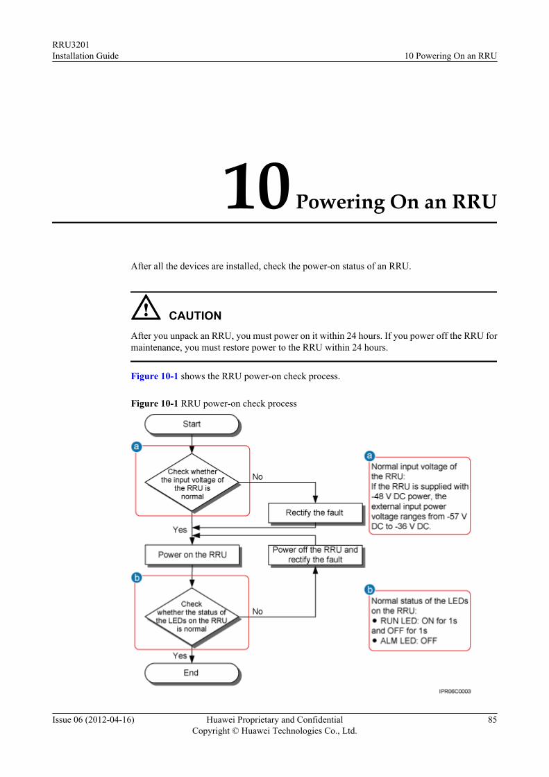
10 Powering On an RRU
After all the devices are installed, check the power-on status of an RRU.
CAUTIONAfter you unpack an RRU, you must power on it within 24 hours. If you power off the RRU formaintenance, you must restore power to the RRU within 24 hours.
Figure 10-1 shows the RRU power-on check process.
Figure 10-1 RRU power-on check process
RRU3201Installation Guide 10 Powering On an RRU
Issue 06 (2012-04-16) Huawei Proprietary and ConfidentialCopyright © Huawei Technologies Co., Ltd.
85
11 Appendix
About This Chapter
This section describes the procedure for adding OT terminals.
11.1 Adding OT Terminals to the RRU Power Cable on the RRU SideThis section describes the procedure for adding OT terminals to the RRU power cable on theRRU side.
RRU3201Installation Guide 11 Appendix
Issue 06 (2012-04-16) Huawei Proprietary and ConfidentialCopyright © Huawei Technologies Co., Ltd.
86
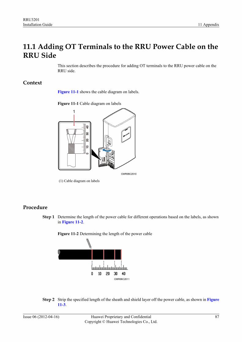
11.1 Adding OT Terminals to the RRU Power Cable on theRRU Side
This section describes the procedure for adding OT terminals to the RRU power cable on theRRU side.
ContextFigure 11-1 shows the cable diagram on labels.
Figure 11-1 Cable diagram on labels
(1) Cable diagram on labels
Procedure
Step 1 Determine the length of the power cable for different operations based on the labels, as shownin Figure 11-2.
Figure 11-2 Determining the length of the power cable
Step 2 Strip the specified length of the sheath and shield layer off the power cable, as shown in Figure11-3.
RRU3201Installation Guide 11 Appendix
Issue 06 (2012-04-16) Huawei Proprietary and ConfidentialCopyright © Huawei Technologies Co., Ltd.
87
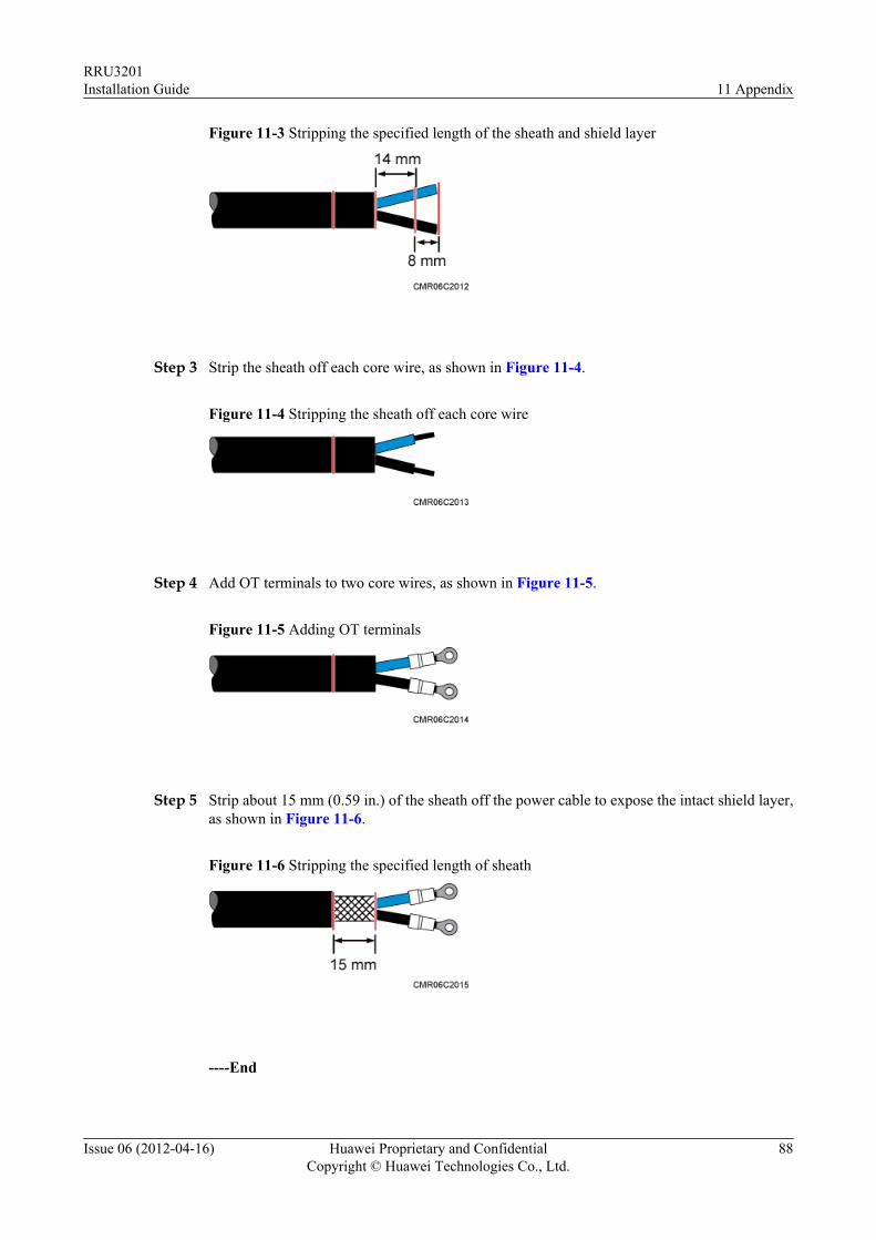
Figure 11-3 Stripping the specified length of the sheath and shield layer
Step 3 Strip the sheath off each core wire, as shown in Figure 11-4.
Figure 11-4 Stripping the sheath off each core wire
Step 4 Add OT terminals to two core wires, as shown in Figure 11-5.
Figure 11-5 Adding OT terminals
Step 5 Strip about 15 mm (0.59 in.) of the sheath off the power cable to expose the intact shield layer,as shown in Figure 11-6.
Figure 11-6 Stripping the specified length of sheath
----End
RRU3201Installation Guide 11 Appendix
Issue 06 (2012-04-16) Huawei Proprietary and ConfidentialCopyright © Huawei Technologies Co., Ltd.
88