Installation Guide - Viconics€¦ · Installation Guide ... All Viconics VT7200 series Room...
18
1 | 028-0190-09 November 2015 CONTENTS Installation 2 Location 2 Installation 2 Configurable BI/UI inputs overview 4 Network ready 6 Terminal, Identification and Function 6 Wiring 7 Main outputs wiring 7 Typical applications 8 Configuring and Status Display Instructions 15 Status display 15 User Interface 17 Local keypad interface 17 VT7200 Series Installation Guide For Commercial HVAC Applications November 2015
Transcript of Installation Guide - Viconics€¦ · Installation Guide ... All Viconics VT7200 series Room...
1 | 028-0190-09 November 2015
CONTENTS
Installation 2 Location 2 Installation 2
Configurable BI/UI inputs overview 4 Network ready 6
Terminal, Identification and Function 6 Wiring 7 Main outputs wiring 7 Typical applications 8
Configuring and Status Display Instructions 15 Status display 15
User Interface 17 Local keypad interface 17
VT7200 Series
Installation Guide
For Commercial HVAC Applicat ions
November 2015

2 | 028-0190-09 November 2015
INSTALLATION Remove security screw on bottom of Room
Controller cover.
Open unit by pulling on bottom side of
Room Controller (fig. 1).
Remove wiring terminals from sticker.
Read FCC ID and IC label installed in
the cover.
Location
1. Should not be installed on outside wall.
2. Must be installed away from any direct
heat source.
3. Should not be installed near an air
discharge grill.
4. Should not be affected by direct sun
radiation.
5. Nothing should restrict vertical air
circulation to Room Controller.
Installation 1. Swing open Room Controller PCB to
left by pressing PCB locking tabs
(fig. 2).
2. Pull out cables 6” out from the wall.
Ensure wall surface is flat and clean.
3. Insert cable in central hole of base.
4. Align base and mark location of two
mounting holes on wall. Install
proper side of base up.
5. Install anchors in wall.
6. Insert screws in mounting holes on
each side of base (fig. 2).
7. Gently swing back circuit board on
base and push until the tabs lock.
8. Strip each wire 1/4 inch from end.
9. Insert each wire according to wiring
diagram.
10. Gently push excess wiring back into
hole (fig. 3).
11. Re-Install wiring terminals in their
correct locations (fig. 3).
12. Re-install cover (top side first) and
gently push extra wire length back
into hole in wall.
13. Install security screw.
3 | 028-0190-09 November 2015
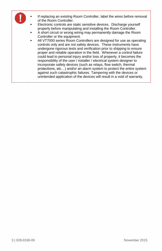
If replacing an existing Room Controller, label the wires before removal of the Room Controller.
Electronic controls are static sensitive devices. Discharge yourself properly before manipulating and installing the Room Controller.
A short circuit or wrong wiring may permanently damage the Room Controller or the equipment.
All VT7000 series Room Controllers are designed for use as operating controls only and are not safety devices. These instruments have undergone rigorous tests and verification prior to shipping to ensure proper and reliable operation in the field. Whenever a control failure could lead to personal injury and/or loss of property, it becomes the responsibility of the user / installer / electrical system designer to incorporate safety devices (such as relays, flow switch, thermal protections, etc…) and/or an alarm system to protect the entire system against such catastrophic failures. Tampering with the devices or unintended application of the devices will result in a void of warranty.
4 | 028-0190-09 November 2015
CONFIGURABLE BI/UI INPUTS OVERVIEW
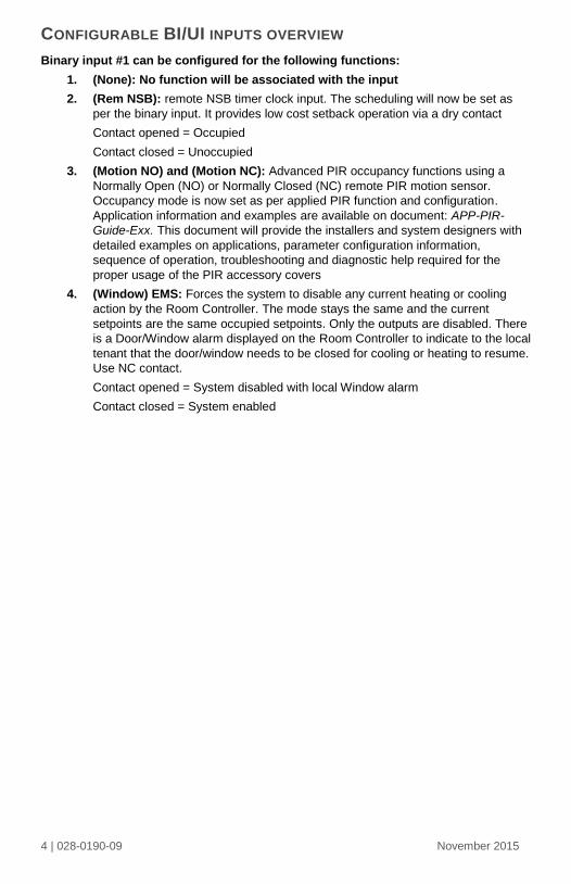
Binary input #1 can be configured for the following functions:
1. (None): No function will be associated with the input
2. (Rem NSB): remote NSB timer clock input. The scheduling will now be set as
per the binary input. It provides low cost setback operation via a dry contact
Contact opened = Occupied
Contact closed = Unoccupied
3. (Motion NO) and (Motion NC): Advanced PIR occupancy functions using a
Normally Open (NO) or Normally Closed (NC) remote PIR motion sensor.
Occupancy mode is now set as per applied PIR function and configuration.
Application information and examples are available on document: APP-PIR-
Guide-Exx. This document will provide the installers and system designers with
detailed examples on applications, parameter configuration information,
sequence of operation, troubleshooting and diagnostic help required for the
proper usage of the PIR accessory covers
4. (Window) EMS: Forces the system to disable any current heating or cooling
action by the Room Controller. The mode stays the same and the current
setpoints are the same occupied setpoints. Only the outputs are disabled. There
is a Door/Window alarm displayed on the Room Controller to indicate to the local
tenant that the door/window needs to be closed for cooling or heating to resume.
Use NC contact.
Contact opened = System disabled with local Window alarm
Contact closed = System enabled
5 | 028-0190-09 November 2015
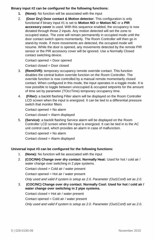
Binary input #2 can be configured for the following functions:
1. (None): No function will be associated with the input
2. (Door Dry) Door contact & Motion detector: This configuration is only
functional if binary input #1 is set to Motion NO or Motion NC or a PIR
accessory cover is used. With this sequence enabled, the occupancy is now
dictated through those 2 inputs. Any motion detected will set the zone to
occupied status. The zone will remain permanently in occupied mode until the
door contact switch opens momentarily. The Room Controller will then go in
stand-by mode. If more movements are detected, the occupied mode will
resume. While the door is opened, any movements detected by the remote PIR
sensor or the PIR accessory cover will be ignored. Use a Normally Closed
contact switching device.
Contact opened = Door opened
Contact closed = Door closed
3. (RemOVR): temporary occupancy remote override contact. This function
disables the central button override function on the Room Controller. The
override function is now controlled by a manual remote momentarily closed
contact. When configured in this mode, the input operates in a toggle mode. It is
now possible to toggle between unoccupied & occupied setpoints for the amount
of time set by parameter (TOccTime) temporary occupancy time.
4. (Filter): a backlit flashing Filter alarm will be displayed on the Room Controller
LCD screen when the input is energized. It can be tied to a differential pressure
switch that monitor filters
Contact opened = No alarm
Contact closed = Alarm displayed
5. (Service): a backlit flashing Service alarm will be displayed on the Room
Controller LCD screen when the input is energized. It can be tied in to the AC
unit control card, which provides an alarm in case of malfunction.
Contact opened = No alarm
Contact closed = Alarm displayed
Universal input #3 can be configured for the following functions:
1. (None): No function will be associated with the input
2. (COC/NH) Change over dry contact. Normally Heat: Used for hot / cold air /
water change over switching in 2 pipe systems.
Contact closed = Cold air / water present
Contact opened = Hot air / water present
Only used and valid if system is setup as 2.0. Parameter (Out1Conf) set as 2.0.
3. (COC/NC) Change over dry contact. Normally Cool: Used for hot / cold air /
water change over switching in 2 pipe systems.
Contact closed = Hot air / water present
Contact opened = Cold air / water present
Only used and valid if system is setup as 2.0. Parameter (Out1Conf) set as 2.0.
6 | 028-0190-09 November 2015
4. (COS) Change over analog sensor: Used for hot / cold air / water change over
switching in 2 pipe systems.
Only used and valid if system is setup as 2.0. Parameter (Out1Conf) set as 2.0.
If temperature is > 77 °F = Hot air / water present
If temperature is < 75 °F = Cold air / water present
5. (SS) Supply air sensor monitoring: Used for supply air temperature
monitoring.
Only used for network reporting of the supply air temperature. Has no internal
function in the Room Controller.
Network ready All Viconics VT7200 series Room Controllers are designed for stand-alone
(Network Ready) operation.
They can be fully integrated into your choice of automation systems using the
available communication adapter options.
If required, stand-alone (Network Ready) Room Controllers can be field
retrofitted with the following communication adapters:
o VCM7300V5000B, Room Controller BACnet™ MS-TP communication
adapter
o VCM7300V5000E, Room Controller Echelon™ Lontalk™
communication adapter
o VCM7000V5000W Room Controller wireless communication adapter
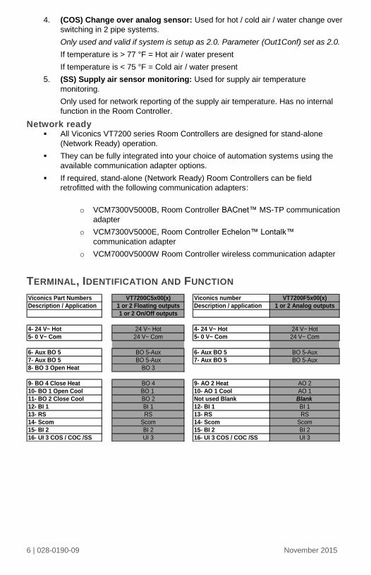
TERMINAL, IDENTIFICATION AND FUNCTION
Viconics Part Numbers VT7200C5x00(x) Viconics number VT7200F5x00(x)
Description / Application 1 or 2 Floating outputs Description / application 1 or 2 Analog outputs
1 or 2 On/Off outputs
4- 24 V~ Hot 24 V~ Hot 4- 24 V~ Hot 24 V~ Hot
5- 0 V~ Com 24 V~ Com 5- 0 V~ Com 24 V~ Com
6- Aux BO 5 BO 5-Aux 6- Aux BO 5 BO 5-Aux
7- Aux BO 5 BO 5-Aux 7- Aux BO 5 BO 5-Aux
8- BO 3 Open Heat BO 3
9- BO 4 Close Heat BO 4 9- AO 2 Heat AO 2
10- BO 1 Open Cool BO 1 10- AO 1 Cool AO 1
11- BO 2 Close Cool BO 2 Not used Blank Blank
12- BI 1 BI 1 12- BI 1 BI 1
13- RS RS 13- RS RS
14- Scom Scom 14- Scom Scom
15- BI 2 BI 2 15- BI 2 BI 2
16- UI 3 COS / COC /SS UI 3 16- UI 3 COS / COC /SS UI 3
7 | 028-0190-09 November 2015
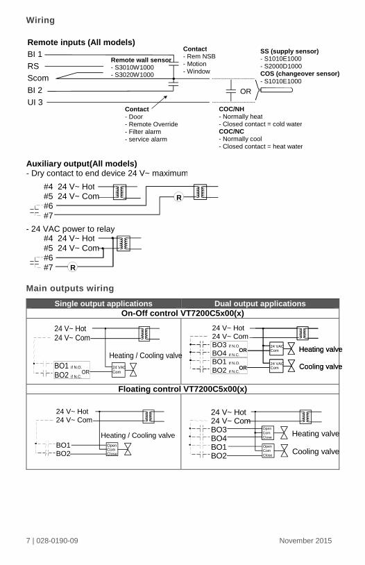
Wiring
Main outputs wiring
Single output applications Dual output applications
On-Off control VT7200C5x00(x)
Floating control VT7200C5x00(x)
Remote inputs (All models)
BI 1
RS
Scom
BI 2
UI 3
OR
Contact - Rem NSB - Motion - Window
Contact - Door - Remote Override - Filter alarm - service alarm
Remote wall sensor - S3010W1000 - S3020W1000
SS (supply sensor) - S1010E1000 - S2000D1000 COS (changeover sensor) - S1010E1000
COC/NH - Normally heat - Closed contact = cold water COC/NC - Normally cool - Closed contact = heat water
#4 24 V~ Hot #5 24 V~ Com #6 #7
#4 24 V~ Hot #5 24 V~ Com #6 #7
Auxiliary output (All models) - Dry contact to end device 24 V~ maximum
- 24 VAC power to relay
R
R
Heating / Cooling valve
24 VAC Com OR
24 V~ Hot 24 V~ Com
BO1 if N.O.
BO2 if N.C.
24 V~ Hot 24 V~ Com
BO3 if N.O.
BO4 if N.C.
BO1 if N.O.
BO2 if N.C.
24 Vac Com Heating valve
Cooling valve 24 Vac Com
OR
OR
24 VAC Com Heating valve
Cooling valve 24 VAC Com
OR
OR
OpenComClose
Heating / Cooling valve
24 V~ Hot
24 V~ Com
BO1BO2
Open
Com
CloseHeating valve
Open
Com
CloseCooling valve
24 V~ Hot24 V~ ComBO3BO4BO1BO2
8 | 028-0190-09 November 2015
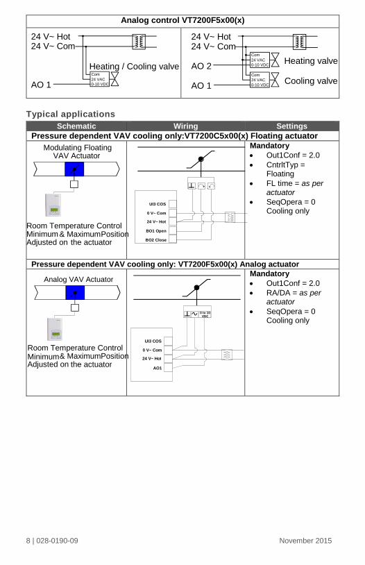
Analog control VT7200F5x00(x)
Typical applications
Schematic Wiring Settings
Pressure dependent VAV cooling only:VT7200C5x00(x) Floating actuator
Mandatory
Out1Conf = 2.0
CntrltTyp = Floating
FL time = as per actuator
SeqOpera = 0 Cooling only
Pressure dependent VAV cooling only: VT7200F5x00(x) Analog actuator
Mandatory
Out1Conf = 2.0
RA/DA = as per actuator
SeqOpera = 0 Cooling only
Heating / Cooling valve Com 24 VAC 0-10 VDC
24 V~ Hot 24 V~ Com
AO 1
24 V~ Hot 24 V~ Com
AO 2
AO 1
Com 24 VAC 0-10 VDC Heating valve
Cooling valve Com 24 VAC 0-10 VDC
UI3 COS
0 V~ Com
24 V~ Hot
BO1 Open
BO2 Close& Maximum Position
the actuator
Modulating Floating VAV Actuator
Analog VAV Actuator
& Maximum Position the actuator
0 to 10 VDC
UI3 COS
0 V~ Com
24 V~ Hot
AO1
Minimum
Minimum Adjusted on
Room Temperature Control
Adjusted on
Room Temperature Control
9 | 028-0190-09 November 2015
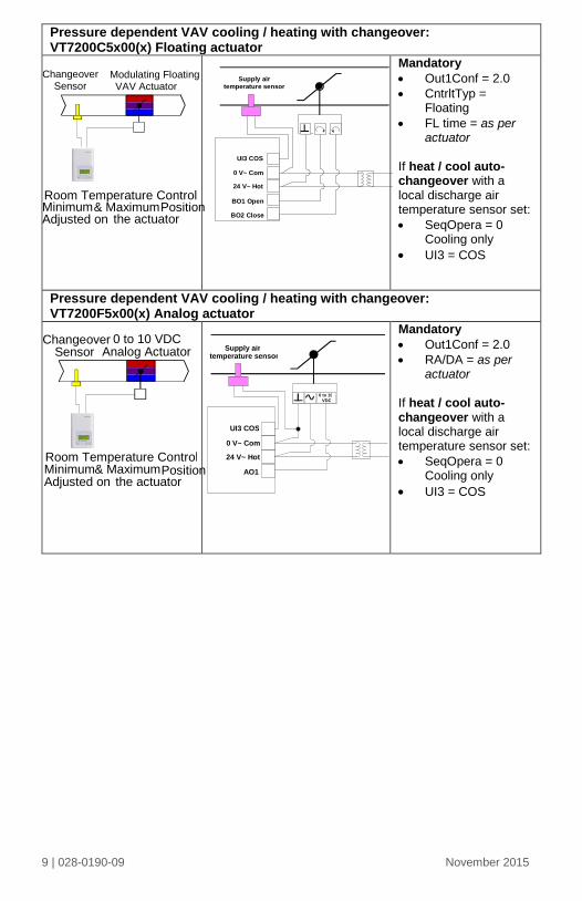
Pressure dependent VAV cooling / heating with changeover: VT7200C5x00(x) Floating actuator
Mandatory
Out1Conf = 2.0
CntrltTyp = Floating
FL time = as per actuator
If heat / cool auto-changeover with a local discharge air temperature sensor set:
SeqOpera = 0 Cooling only
UI3 = COS
Pressure dependent VAV cooling / heating with changeover: VT7200F5x00(x) Analog actuator
Mandatory
Out1Conf = 2.0
RA/DA = as per actuator
If heat / cool auto-changeover with a local discharge air temperature sensor set:
SeqOpera = 0 Cooling only
UI3 = COS
Supply airtemperature sensor
UI3 COS
0 V~ Com
24 V~ Hot
BO1 Open
BO2 Close
Changeover Sensor
Room Temperature Control & Maximum Position
the actuator
Modulating Floating VAV Actuator
0 to 10 VDC Analog Actuator
Changeover Sensor
Room Temperature Control Minimum & Maximum Adjusted on the actuator
Position
Supply air temperature sensor
0 to 10 VDC
UI3 COS
0 V~ Com
24 V~ Hot
AO1
Minimum Adjusted on
10 | 028-0190-09 November 2015
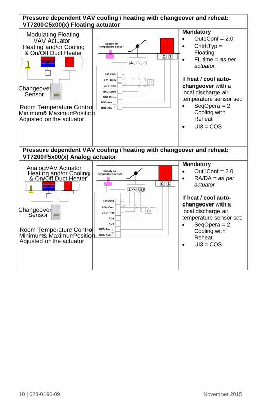
Pressure dependent VAV cooling / heating with changeover and reheat: VT7200C5x00(x) Floating actuator
Mandatory
Out1Conf = 2.0
CntrltTyp = Floating
FL time = as per actuator
If heat / cool auto-changeover with a local discharge air temperature sensor set:
SeqOpera = 2 Cooling with Reheat
UI3 = COS
Pressure dependent VAV cooling / heating with changeover and reheat: VT7200F5x00(x) Analog actuator
Mandatory
Out1Conf = 2.0
RA/DA = as per actuator
If heat / cool auto-changeover with a local discharge air temperature sensor set:
SeqOpera = 2 Cooling with Reheat
UI3 = COS
Supply airtemperature sensor
1C
UI3 COS
0 V~ Com
24 V~ Hot
BO1 Open
BO2 Close
BO5-Aux
BO5-Aux
Sensor
Room Temperature Control & Maximum Position
Adjusted on the actuator
Modulating Floating VAV Actuator
Heating and/or Cooling & On/Off Duct Heater
Minimum
Sensor
Analog VAV Actuator Heating and/or Cooling & On/Off Duct Heater
& Maximum Position the actuator
Minimum Adjusted on
Room Temperature Control
Supply air temperature sensor
1 C 0 to 10 VDC
UI3 COS 0 V~ Com 24 V~ Hot
AO1
BO5-Aux BO5-Aux
AO2
Changeover
Changeover
11 | 028-0190-09 November 2015
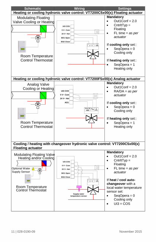
Schematic Wiring Settings
Heating or cooling hydronic valve control: VT7200C5x00(x) Floating actuator
Mandatory
Out1Conf = 2.0
CntrltTyp = Floating
FL time = as per actuator
If cooling only set::
SeqOpera = 0 Cooling only
If heating only set::
SeqOpera = 1 Heating only
Heating or cooling hydronic valve control: VT7200F5x00(x) Analog actuator
Mandatory
Out1Conf = 2.0
RA/DA = as per actuator
If cooling only set::
SeqOpera = 0 Cooling only
If heating only set::
SeqOpera = 1 Heating only
Cooling / heating with changeover hydronic valve control: VT7200C5x00(x) Floating actuator
Mandatory
Out1Conf = 2.0
CntrltTyp = Floating
FL time = as per actuator
If heat / cool auto-changeover with a local water temperature sensor set:
SeqOpera = 0 Cooling only
UI3 = COS
UI3 COS
0 V~ Com
24 V~ Hot
BO1 Open
BO2 Close
Supply watertemperature sensor
UI3 COS
0 V~ Com
24 V~ Hot
BO1 Open
BO2 Close
Modulating Floating Valve Cooling or Heating
Room Temperature Control Thermostat
Analog Valve Cooling or Heating
Room Temperature Control Thermostat
0 to 10 VDC
UI3 COS
0 V~ Com
24 V~ Hot
AO1
Modulating Floating Valve Heating and/or Cooling
Optional Water
Supply Sensor
Room Temperature Control Thermostat
12 | 028-0190-09 November 2015
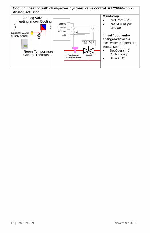
Cooling / heating with changeover hydronic valve control: VT7200F5x00(x) Analog actuator
Mandatory
Out1Conf = 2.0
RA/DA = as per actuator
If heat / cool auto-changeover with a local water temperature sensor set:
SeqOpera = 0 Cooling only
UI3 = COS
Analog Valve Heating and/or Cooling
Optional Water Supply Sensor
Room Temperature Control Thermostat Supply water
temperature sensor
0 to 10 VDC
UI3 COS
0 V~ Com 24 V~ Hot
AO1
13 | 028-0190-09 November 2015
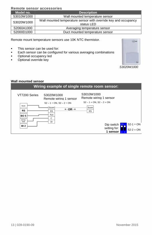
Remote sensor accessories Model no. Description
S3010W1000 Wall mounted temperature sensor
S3020W1000 Wall mounted temperature sensor with override key and occupancy
status LED
S2060A1000 Averaging temperature sensor
S2000D1000 Duct mounted temperature sensor
Remote mount temperature sensors use 10K NTC thermistor.
This sensor can be used for: Each sensor can be configured for various averaging combinations Optional occupancy led Optional override key
S3020W1000
Wall mounted sensor
Wiring example of single remote room sensor:
S3020W1000 Remote wiring 1 sensor S2=On, S3=On
VT7200 Series
BO 5
BI 2
RS
Scom Scom
RS Scom
RS
C DI
Aux
Scom RS
Scom RS
OR
S3010W1000 Remote wiring 1 sensor S2=On, S3=On
24 Vac Com
1 2
O NDip switch setting for: 1 sensor
S2-1 = ON
S2-2 = ON
S2 – 1 = ON, S2 – 2 = ON S2 – 1 = ON, S2 – 2 = ON
14 | 028-0190-09 November 2015
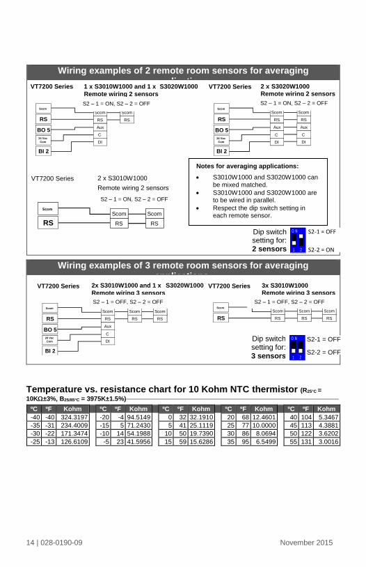
Wiring examples of 2 remote room sensors for averaging applications:
Wiring examples of 3 remote room sensors for averaging applications:
Temperature vs. resistance chart for 10 Kohm NTC thermistor (R25°C =
10K±3%, B25/85°C = 3975K±1.5%)
ºC ºF Kohm ºC ºF Kohm ºC ºF Kohm ºC ºF Kohm ºC ºF Kohm
-40 -40 324.3197 -20 -4 94.5149 0 32 32.1910 20 68 12.4601 40 104 5.3467
-35 -31 234.4009 -15 5 71.2430 5 41 25.1119 25 77 10.0000 45 113 4.3881
-30 -22 171.3474 -10 14 54.1988 10 50 19.7390 30 86 8.0694 50 122 3.6202
-25 -13 126.6109 -5 23 41.5956 15 59 15.6286 35 95 6.5499 55 131 3.0016
Notes for averaging applications:
S3010W1000 and S3020W1000 can be mixed matched.
S3010W1000 and S3020W1000 are to be wired in parallel.
Respect the dip switch setting in each remote sensor.
1 x S3010W1000 and 1 x S3020W1000 Remote wiring 2 sensors S1=On, S2=Off
Scom RS
Scom RS
VT7200 Series
BO 5
BI 2
RS
Scom
24 Vac Com
Scom RS
Scom RS
C DI
Aux
2 x S3020W1000 Remote wiring 2 sensors S2=On, S3=Off
Scom RS
Scom RS
C DI
Aux
VT7200 Series
BO 5
BI 2
RS
Scom
24 Vac Com
Scom RS
Scom RS
C DI
Aux
2 x S3010W1000
Remote wiring 2 sensors
S2=On, S3=Off
Scom RS
Scom RS
VT7200 Series
RS
Scom Scom
RS Scom
RS
2x S3010W1000 and 1 x S3020W1000 Remote wiring 3 sensors S2=Off, S3=Off
Scom RS
Scom RS
Scom RS
Scom RS
VT7200 Series
BO 5
BI 2
RS
Scom
24 Vac Com
Scom RS
Scom RS
C DI
Aux
3x S3010W1000 Remote wiring 3 sensors S2=Off, S3=Off
Scom RS
Scom RS
Scom RS
Scom RS
VT7200 Series
RS
Scom Scom
RS Scom
RS
1 2
O NDip switch setting for: 2 sensors
S2-1 = OFF
S2-2 = ON
1 2
O NDip switch setting for: 3 sensors
S2-1 = OFF
S2-2 = OFF
S2 – 1 = ON, S2 – 2 = OFF S2 – 1 = ON, S2 – 2 = OFF
S2 – 1 = ON, S2 – 2 = OFF
S2 – 1 = OFF, S2 – 2 = OFF S2 – 1 = OFF, S2 – 2 = OFF
15 | 028-0190-09 November 2015
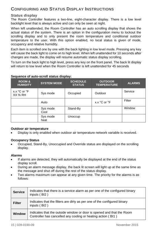
CONFIGURING AND STATUS DISPLAY INSTRUCTIONS
Status display The Room Controller features a two-line, eight-character display. There is a low level
backlight level that is always active and can only be seen at night.
When left unattended, the Room Controller has an auto scrolling display that shows the
actual status of the system. There is an option in the configuration menu to lockout the
scrolling display and to only present the room temperature and conditional outdoor
temperature to the user. With this option enabled, no local status is given of mode,
occupancy and relative humidity.
Each item is scrolled one by one with the back lighting in low level mode. Pressing any key
will cause the back light to come on to high level. When left unattended for 10 seconds after
changes are made, the display will resume automatic status display scrolling.
To turn on the back light to high level, press any key on the front panel. The back lit display
will return to low level when the Room Controller is left unattended for 45 seconds
Sequence of auto-scroll status display:
ROOM & HUMIDITY
SYSTEM MODE SCHEDULE
STATUS OUTDOOR
TEMPERATURE ALARMS
x.x °C or °F XX % RH
Sys mode Occupied Outdoor Service
Auto x.x °C or °F Filter
Sys mode Cool
Stand-By
Window
Sys mode heat
Unoccup
Outdoor air temperature
Display is only enabled when outdoor air temperature network variable is received. Occupancy Status
Occupied, Stand-By, Unoccupied and Override status are displayed on the scrolling display.
Alarms
If alarms are detected, they will automatically be displayed at the end of the status display scroll.
During an alarm message display, the back lit screen will light up at the same time as the message and shut off during the rest of the status display.
Two alarms maximum can appear at any given time. The priority for the alarms is as follows:
Service Indicates that there is a service alarm as per one of the configured binary inputs ( BI2 )
Filter Indicates that the filters are dirty as per one of the configured binary inputs ( BI2 )
Window Indicates that the outside window or door is opened and that the Room Controller has cancelled any cooling or heating action ( BI1 )
16 | 028-0190-09 November 2015
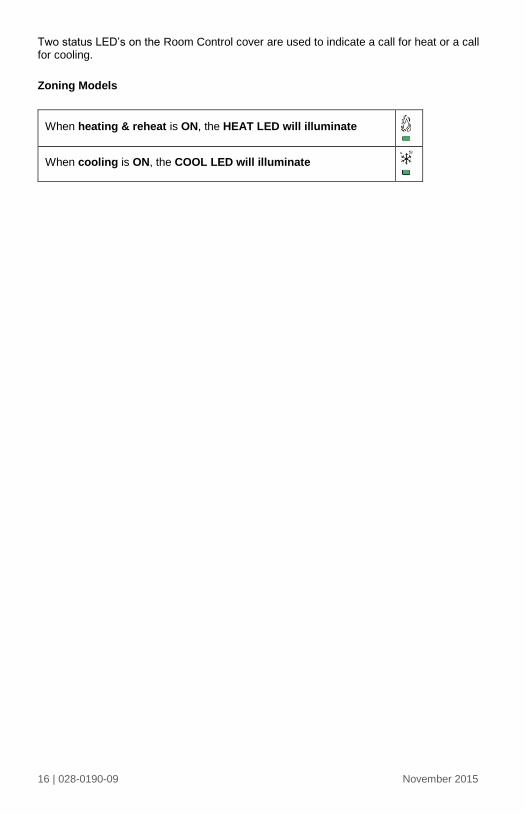
Two status LED’s on the Room Control cover are used to indicate a call for heat or a call for cooling.
Zoning Models
When heating & reheat is ON, the HEAT LED will illuminate
When cooling is ON, the COOL LED will illuminate
17 | 028-0190-09 November 2015
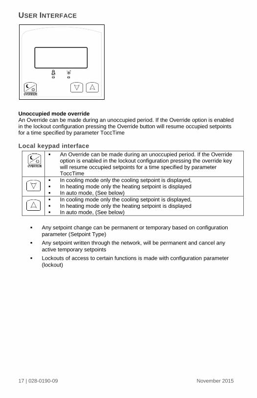
USER INTERFACE
Unoccupied mode override An Override can be made during an unoccupied period. If the Override option is enabled in the lockout configuration pressing the Override button will resume occupied setpoints for a time specified by parameter ToccTime
Local keypad interface
Any setpoint change can be permanent or temporary based on configuration
parameter (Setpoint Type)
Any setpoint written through the network, will be permanent and cancel any
active temporary setpoints
Lockouts of access to certain functions is made with configuration parameter
(lockout)
An Override can be made during an unoccupied period. If the Override option is enabled in the lockout configuration pressing the override key will resume occupied setpoints for a time specified by parameter ToccTime
In cooling mode only the cooling setpoint is displayed, In heating mode only the heating setpoint is displayed In auto mode, (See below)
In cooling mode only the cooling setpoint is displayed, In heating mode only the heating setpoint is displayed In auto mode, (See below)

18 | 028-0190-09 November 2015
Viconics Technologies Inc.
Tel.: Fax: Toll free:
www.viconics.com