Installation Guide EF-A1000 Series -...
12
IG_EF-A1000-T_R1A IG_EF-A1000-T_R1A EBTRON, Inc. 1663 Hwy. 701 S., Loris SC 29569 • Toll Free: 800.2EBTRON (232.8766) • Fax: 843.756.1838 • Internet: EBTRON.com a measurable difference! ® Thermal Dispersion Airflow Measurement Technology Part Number: 930-0195 Installation Guide EF-A1000 Series Analog Output Electronic Low Flow (ELF) Airflow/Temperature Measurement Station Document: IG_EF-A1000-T_R1A EF-A1000-T, EF-A1001-T ELF Quick Installation Guide EB-Flow Electronic Low Flow ELF Analog Output Measurement Station
Transcript of Installation Guide EF-A1000 Series -...

IG_E
F-A1
00
0-T
_R1
AIG
_EF-
A10
00
-T_R
1A
EBTRON, Inc. 1663 Hwy. 701 S., Loris SC 29569 • Toll Free: 800.2EBTRON (232.8766) • Fax: 843.756.1838 • Internet: EBTRON.com
a measurable difference!
®
Thermal Dispersion Airflow Measurement Technology
Part Number: 930-0195
Installation Guide
EF-A1000 SeriesAnalog Output Electronic Low Flow (ELF)Airflow/Temperature Measurement Station
Document: IG_EF-A1000-T_R1A
EF-A1000-T, EF-A1001-T ELFQuick Installation Guide
EB-Flow Electronic Low Flow ELF Analog Output Measurement Station

IG_E
F-A1
00
0-T
_R1
A
a measurable difference!
®
EB-FLOW EF-A1000, EF-A1001 ELFINSTALLATION GUIDE - ELECTRONIC LOW FLOW ‘ELF’ ANALOG OUTPUT
EBTRON, Inc. 1663 Hwy. 701 S., Loris SC 29569 • Toll Free: 800.2EBTRON (232.8766) • Fax: 843.756.1838 • Internet: EBTRON.com2
1. INTRODUCTION AND SCOPE . . . . . . . . . . . . . . . . . . . . . . . . . . . . . . . . . . . . . . . . . . . . . . . . . . . . . . . . . . . . . . . . . . . . . . . . . . . . .3
2. EF-A1000, EF-A1001 INSTALLATION . . . . . . . . . . . . . . . . . . . . . . . . . . . . . . . . . . . . . . . . . . . . . . . . . . . . . . . . . . . . . . . . . . . . . .4
3. ELF PREPARATION FOR USE . . . . . . . . . . . . . . . . . . . . . . . . . . . . . . . . . . . . . . . . . . . . . . . . . . . . . . . . . . . . . . . . . . . . . . . . . . . . .6
4. ELF INTERCONNECTIONS . . . . . . . . . . . . . . . . . . . . . . . . . . . . . . . . . . . . . . . . . . . . . . . . . . . . . . . . . . . . . . . . . . . . . . . . . . . . . . .64.1 ELF 24 VAC Power Connections . . . . . . . . . . . . . . . . . . . . . . . . . . . . . . . . . . . . . . . . . . . . . . . . . . . . . . . . . . . . . . . . . . . . .74.2 ELF Analog Output Connections . . . . . . . . . . . . . . . . . . . . . . . . . . . . . . . . . . . . . . . . . . . . . . . . . . . . . . . . . . . . . . . . . . . . .7
4.2.1 Converting the ELF Analog Output for 4-wire Current Loops . . . . . . . . . . . . . . . . . . . . . . . . . . . . . . . . . . . . . . . .7
5. ELF ANALOG OUTPUT CONFIGURATION OPTIONS (CONFIG SW1 - SW4) . . . . . . . . . . . . . . . . . . . . . . . . . . . . . . . . . . . . . . . . . .7
6. ELF INITIAL START UP / NORMAL OPERATION . . . . . . . . . . . . . . . . . . . . . . . . . . . . . . . . . . . . . . . . . . . . . . . . . . . . . . . . . . . . .116.1 Converting the Analog Airflow Output Signal from Linear to Volumetric flow - FPM to CFM . . . . . . . . . . . . . . . . . . . .11
7. ELF ADDITIONAL INFORMATION . . . . . . . . . . . . . . . . . . . . . . . . . . . . . . . . . . . . . . . . . . . . . . . . . . . . . . . . . . . . . . . . . . . . . . . . .11
Table of Contents
Figure 1. ELF Installation Applications and Orientation . . . . . . . . . . . . . . . . . . . . . . . . . . . . . . . . . . . . . . . . . . . . . . . . . . . . . . . . .5
Figure 2. ELF Installation Dimensions . . . . . . . . . . . . . . . . . . . . . . . . . . . . . . . . . . . . . . . . . . . . . . . . . . . . . . . . . . . . . . . . . . . . . . .6
Figure 3. ELF Main Circuit Board and Configuration Option Selector Detail . . . . . . . . . . . . . . . . . . . . . . . . . . . . . . . . . . . . . . . . .8
Figure 4. EF-A1000 ELF Single Output Power and Signal Wiring Interconnections . . . . . . . . . . . . . . . . . . . . . . . . . . . . . . . . . . .9
Figure 5. EF-A1001 ELF Dual Output Power and Signal Wiring Interconnections . . . . . . . . . . . . . . . . . . . . . . . . . . . . . . . . . . .10
List of TablesTable 1. CONFIG Switch Settings . . . . . . . . . . . . . . . . . . . . . . . . . . . . . . . . . . . . . . . . . . . . . . . . . . . . . . . . . . . . . . . . . . . . . . . . . . .7
List of Figures
Copyright © EBTRON®, Inc.All brand names, trademarks and registered trademarks are the property of their respective owners. Information contained within this document is subject to
change without notice. Visit EBTRON.com to view and/or download the most recent versions of this and other documents.
All rights reserved.
LIST OF EFFECTIVE AND CHANGED PAGES
Insert latest changed pages (in bold text); remove and dispose of superseded pages.Total number of pages in this manual is 12.
Page No Revision * Description of Change Date1 through 12 . . . . . . . . . . .R1A . . . . . . . . . . . . .Initial document release. . . . . . . . . . . . . . . . . . . . . . . . . . . . . . . . . . . . . . . . . . . . . . . . . . . . .1/25/2016
* R1A indicates an original page without change

IG_E
F-A1
00
0-T
_R1
A
a measurable difference!
®
EB-FLOW EF-A1000, EF-A1001 ELFINSTALLATION GUIDE - ELECTRONIC LOW FLOW ‘ELF’ ANALOG OUTPUT
EBTRON, Inc. 1663 Hwy. 701 S., Loris SC 29569 • Toll Free: 800.2EBTRON (232.8766) • Fax: 843.756.1838 • Internet: EBTRON.com 3
1. INTRODUCTION AND SCOPEThis Quick Installation Guide provides basic installation information for the instrument installer. Information includesphysical instrument installation, power and output cable connections as well as initial setup of the instrument. The selfcontained electronic low flow instrument in this document is referred to as the ELF.
Models covered in this document are as follows:Single Analog Output, Single Sensor (4" Probe)EF-A1110 0-10/2-10VDC Single Analog Output with Flow Integration (4" Single Sensor)EF-A1110 /A1 0-5/1-5VDC Single Analog Output with Flow Integration (4" Single Sensor)
Dual Analog Output, Single Sensor (4" Probe)EF-A1111 0-10/2-10VDC Dual Analog Output with Flow Integration (4" Single Sensor)EF-A1111 /A1 0-5/1-5VDC Dual Analog Output with Flow Integration (4" Single Sensor)
Single Analog Output, Two Sensors (>4" Probe)EF-A1120 0-10/2-10VDC Single Analog Output with Flow Integration (>4" Two Sensors)EF-A1120 /A1 0-5/1-5VDC Single Analog Output with Flow Integration (>4" Two Sensors)
Dual Analog Output, Two Sensors (>4" Probe)EF-A1121 0-10/2-10VDC Dual Analog Output with Flow Integration (>4" Two Sensors)EF-A1121 /A1 0-5/1-5VDC Dual Analog Output with Flow Integration (>4" Two Sensors)
For complete and detailed specifications, operating instructions and technical information, refer to the separateInstallation, Operation and Maintenance Technical Manual TM_EF-A1000 under separate cover.

IG_E
F-A1
00
0-T
_R1
A
a measurable difference!
®
EB-FLOW EF-A1000, EF-A1001 ELFINSTALLATION GUIDE - ELECTRONIC LOW FLOW ‘ELF’ ANALOG OUTPUT
EBTRON, Inc. 1663 Hwy. 701 S., Loris SC 29569 • Toll Free: 800.2EBTRON (232.8766) • Fax: 843.756.1838 • Internet: EBTRON.com4
2. EF-A1000, EF-A1001 INSTALLATIONThe ELF instruments are designed for use in small ducts and in VAV terminal box applications in an environment between-20°F to 120°F (-28.9°C to 48.9°C) where it will not be exposed to rain or snow. The ELF airflow measurement stationsensor probes are designed for insertion mounting through one side of the duct or VAV box sidewall. Mount the instru-ment in an accessible location to permit set up. Locate the instrument so that the attached instrument cable will reachthe customer provided BAS control interface.
CAUTION
The installed location of the ELF is critical for proper performance. Refer to theMinimum Placement Guidelines in Technical Manual TM_EF-A1000 to determine theexact location recommended for the instrument.
The installed accuracy of the ELF is ensured in applications where the maximuminside duct dimension is 16 inches or less. Applications in larger duct sizes maydegrade accuracy. Consult factory for these applications.
Ensure that adequate clearance exists around the duct to permit insertion of theprobe, and to allow clearance for the instrument enclosure.
Insulation that interferes with probe mounting should be temporarily removed prior toinstallation. Mounting requires a 0.875 inches (22.2 mm) hole on the insertion side ofthe duct or VAV terminal box.
1. Determine where the ELF airflow measuring station is to be located as indicated on the engineer's plans.
2. Carefully open the ELF package and inspect for damage. If damage is noted, immediately file a claim with carrier.
3. Locate and mark the point on the duct or VAV box where the probe will be inserted, using the Minimum PlacementGuidelines section of Technical Manual TM_EF-A1000. Figures 1 and 2 show ELF installation detail, probe orienta-tion and dimensions.
4. Using a 0.875 inches (22.2 mm) hole saw, drill the insertion side hole where marked.
5. Place the probe through the mounting hole, making sure that the gasket is seated firmly against the integral mount-ing bracket. Ensure that the edge of the ELF mounting bracket is parallel to the edge of the duct or VAV terminalbox, and that the airflow arrow printed on it is oriented in the direction of actual airflow. Ensure that the gasket isfirmly seated against the bracket, and then fasten the mounting bracket at the four mounting holes using appropri-ate sheet metal screws.
6. Route the ELF instrument cable to the customer provided BAS interface. The following sections of this documentdescribe instrument set up and operation.

IG_E
F-A1
00
0-T
_R1
A
a measurable difference!
®
EB-FLOW EF-A1000, EF-A1001 ELFINSTALLATION GUIDE - ELECTRONIC LOW FLOW ‘ELF’ ANALOG OUTPUT
EBTRON, Inc. 1663 Hwy. 701 S., Loris SC 29569 • Toll Free: 800.2EBTRON (232.8766) • Fax: 843.756.1838 • Internet: EBTRON.com 5Figure 1. ELF Installation Applications and Orientation
INSTALLING THE ELF IN DUCTED APPLICATIONSROUND DUCT PLACEMENT
Across major axis Across minor axis
1/2 X 1/2 X
RECTANGULAR DUCT PLACEMENT
1/2 X 1/2 X
1/2 X
1/2 X
FLAT-OVAL DUCT PLACEMENT
Boxes with pneumatic flow rings:
Remove existing flow ring. Locate ELF
3 inches (minimum) upstream of box, OR
3 inches (minimum) upstream of flow ring.
Boxes with no flow rings:
Locate ELF 3 inches (minimum)
upstream of box.
EBTRON ELF
Actuator
(by others)
VAV Box (by others)
ELF PROBE VAV BOX INSTALLATION
Airflow
ELF DOWNSTREAM OF VAV BOX WITH H/W COILS
Airflow Airflow
VAV Terminal Box with H/W Reheat
EBTRONELF
Damper Actuator
Note:This application is not recommended for VAV boxes with electric reheat.
Locate ELF as close as 1 duct diameter downstream
Of VAV box transition
Hot Water Reheat Coil
Transition
1D
SUPPLY AIR FROM AHU
SPACE AIR
Terminal Unit DDC
Controller
EbtronELF
HWR
HWS
2-Way or 3-Way HW Control
Valve
TEMP
FLO
WG
ND24
V
EBTRON ELF
24 VAC POWER INPUT
24 VAC COM / SIGNAL COM
ANALOG AIRFLOW OUT
RED
BLACK
W HI TE
4- CONDUCTORSHIELDED CABLE
INCLUDED WITH ELF
ANALOG TEMPERATURE OUTGREEN
IG_E
F-A1
00
0-T
_R1
A
a measurable difference!
®
EB-FLOW EF-A1000, EF-A1001 ELFINSTALLATION GUIDE - ELECTRONIC LOW FLOW ‘ELF’ ANALOG OUTPUT
EBTRON, Inc. 1663 Hwy. 701 S., Loris SC 29569 • Toll Free: 800.2EBTRON (232.8766) • Fax: 843.756.1838 • Internet: EBTRON.com6
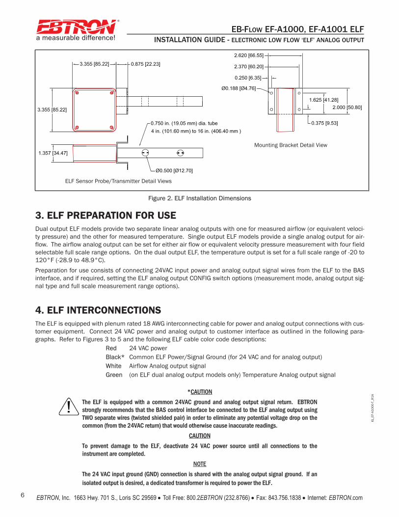
Figure 2. ELF Installation Dimensions
3. ELF PREPARATION FOR USEDual output ELF models provide two separate linear analog outputs with one for measured airflow (or equivalent veloci-ty pressure) and the other for measured temperature. Single output ELF models provide a single analog output for air-flow. The airflow analog output can be set for either air flow or equivalent velocity pressure measurement with four fieldselectable full scale range options. On the dual output ELF, the temperature output is set for a full scale range of -20 to120°F (-28.9 to 48.9°C).
Preparation for use consists of connecting 24VAC input power and analog output signal wires from the ELF to the BASinterface, and if required, setting the ELF analog output CONFIG switch options (measurement mode, analog output sig-nal type and full scale measurement range options).
4. ELF INTERCONNECTIONSThe ELF is equipped with plenum rated 18 AWG interconnecting cable for power and analog output connections with cus-tomer equipment. Connect 24 VAC power and analog output to customer interface as outlined in the following para-graphs. Refer to Figures 3 to 5 and the following ELF cable color code descriptions:
Red 24 VAC powerBlack* Common ELF Power/Signal Ground (for 24 VAC and for analog output)White Airflow Analog output signalGreen (on ELF dual analog output models only) Temperature Analog output signal
*CAUTIONThe ELF is equipped with a common 24VAC ground and analog output signal return. EBTRONstrongly recommends that the BAS control interface be connected to the ELF analog output usingTWO separate wires (twisted shielded pair) in order to eliminate any potential voltage drop on thecommon (from the 24VAC return) that would otherwise cause inaccurate readings.
CAUTIONTo prevent damage to the ELF, deactivate 24 VAC power source until all connections to theinstrument are completed.
NOTEThe 24 VAC input ground (GND) connection is shared with the analog output signal ground. If anisolated output is desired, a dedicated transformer is required to power the ELF.
Mounting Bracket Detail View
ELF Sensor Probe/Transmitter Detail Views

IG_E
F-A1
00
0-T
_R1
A
a measurable difference!
®
EB-FLOW EF-A1000, EF-A1001 ELFINSTALLATION GUIDE - ELECTRONIC LOW FLOW ‘ELF’ ANALOG OUTPUT
EBTRON, Inc. 1663 Hwy. 701 S., Loris SC 29569 • Toll Free: 800.2EBTRON (232.8766) • Fax: 843.756.1838 • Internet: EBTRON.com 7
4.1 ELF 24 VAC Power ConnectionsThe ELF requires a power source capable of providing 22.8 to 26.4 VAC at 5 VA.
CAUTION
24 VAC power must be deactivated before making connections to the instrument.
Connect 24VAC power between the red wire and black wire as shown in Figures 4 and 5.
4.2 ELF Analog Output ConnectionsThe ELF provides separate 0-10VDC (or 2-10VDC) analog outputs corresponding to airflow (or equivalent velocity pres-sure) and temperature. The outputs are capable of driving 20mA loads. The analog outputs are not isolated from theinput power. The 24VAC input ground connection is shared with the analog signal ground (black wire - GND). If isolat-ed outputs are required, the ELF must be powered by a dedicated transformer.
Connect the analog airflow output (white wire), temperature output (green wire on EF-A1001 only) and the signal com-mon (black wire) to the BAS monitor/control interface using shielded twisted pair cable as shown in Figures 4 and 5.
4.2.1 Converting the ELF Analog Output for 4-wire Current Loops The VDC output circuit of the EF-A1000 transmitter can drive the input circuit of devices designed to measure 4-wirecurrent loops with a resistive load ≥250 ohms.
5. ELF ANALOG OUTPUT CONFIGURATION OPTIONS (CONFIG SW1 - SW4)To access the field selectable analog output configuration switches, remove the four retaining screws at each corner ofthe ELF enclosure cover. Configuration selector switches SW1 through SW4 are part of a four-switch DIP package labeledCONFIG. Figure 3 shows the ELF main circuit board and the individual switches for setting the output measurementmode, analog output voltage range and output full scale values. Factory default switch settings are all OFF. The tablebelow shows the CONFIG switch settings and resulting operation for each of the ELF model versions.
Table 1. CONFIG Switch Settings
OFF ON OFF ON OFF/OFF ON/OFF OFF/ON ON/ON
3000 FPM 2000 FPM 1000 FPM 500 FPM0.5 Iwc 0.25 Iwc 0.15 Iwc 0.05 Iwc
3000 FPM 2000 FPM 1000 FPM 500 FPM0 5 I 0 25 I 0 15 I 0 05 I
STANDARD(NO /A1 SUFFIX)
/A1 MODEL SUFFIX
SW POSITION>
OUTPUT OPTION
SW3/SW4 POSITIONAIR FLOWMEASUREMENT RANGE SELECT
SW1 POSITIONMEASUREMENT MODE
0 10VDC 2 10VDC
0 5VDC 1 5VDC
SW2 POSITIONANALOG OUT SELECT
AIRFLOW VEL PRESSURE
AIRFLOW VEL PRESSURE0.5 Iwc 0.25 Iwc 0.15 Iwc 0.05 Iwc
BOLD TYPEFACE INDICATES FACTORY DEFAULT SWITCH SETTINGS
/A1 MODEL SUFFIX 0 5VDC 1 5VDCAIRFLOW VEL PRESSURE

IG_E
F-A1
00
0-T
_R1
A
a measurable difference!
®
EB-FLOW EF-A1000, EF-A1001 ELFINSTALLATION GUIDE - ELECTRONIC LOW FLOW ‘ELF’ ANALOG OUTPUT
8
IG_E
F-A1
00
0-T
_R1
A
EBTRON, Inc. 1663 Hwy. 701 S., Loris SC 29569 • Toll Free: 800.2EBTRON (232.8766) • Fax: 843.756.1838 • Internet: EBTRON.com 8
Figure 3. ELF Main Circuit Board and Configuration Option Selector Detail
CONFIG DIP Switch Detail
SW1
SW2
SW3
SW4
ACTIVITY GREEN LEDNORMAL: 1 Second ON/OFF FlashFAULT: 2 Second ON/OFF Flash
MOUNTINGBRACKET
GASKET
INTEGRAL MOUNTINGBRACKET
SW1-SW4 CONFIGDIP SWITCH SELECTOR
SW1 - AIRFLOW or EQUIVALENTVELOCITY PRESSURE
SW2 - ANALOG OUT SELECTSW3 / SW4 - OUTPUT SCALE
(See Detail below)
SENSORPROBE
IG_E
F-A1
00
0-T
_R1
A
a measurable difference!
®
EB-FLOW EF-A1000, EF-A1001 ELFINSTALLATION GUIDE - ELECTRONIC LOW FLOW ‘ELF’ ANALOG OUTPUT
EBTRON, Inc. 1663 Hwy. 701 S., Loris SC 29569 • Toll Free: 800.2EBTRON (232.8766) • Fax: 843.756.1838 • Internet: EBTRON.com 9
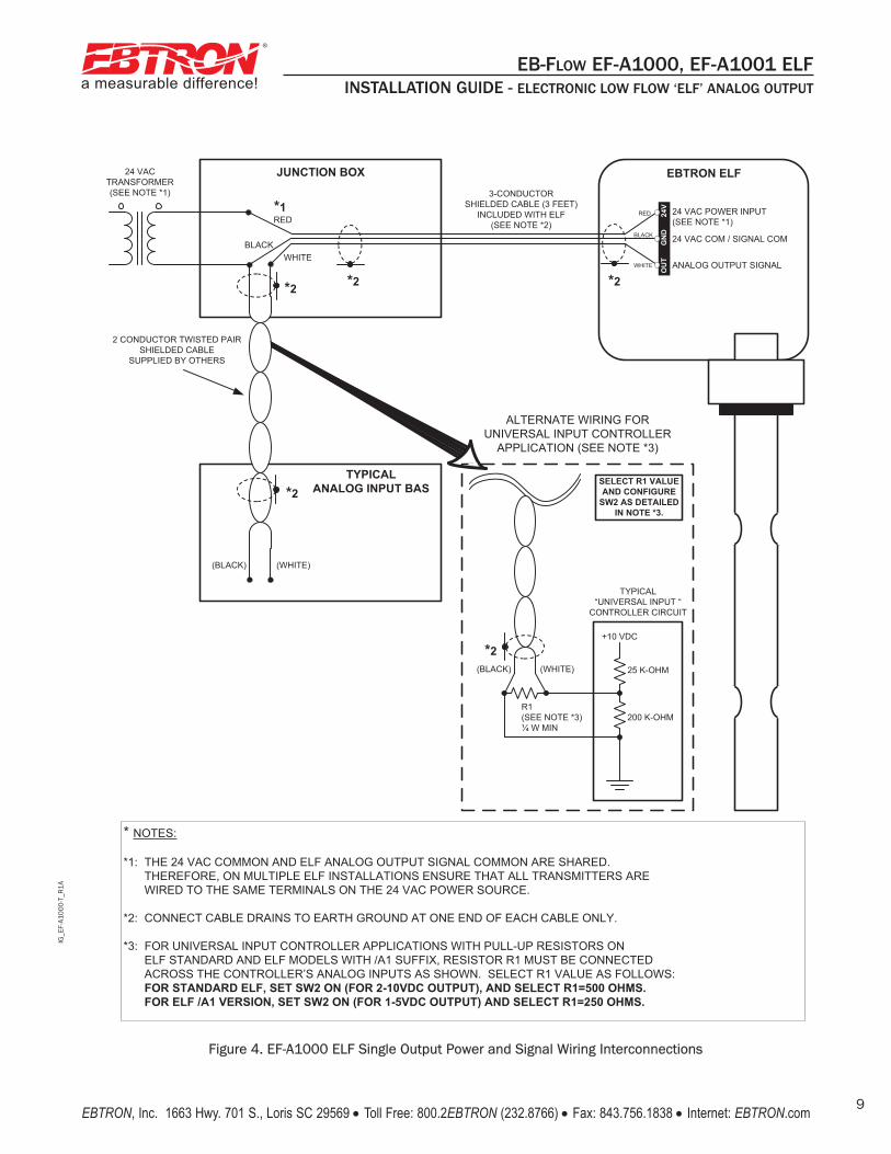
Figure 4. EF-A1000 ELF Single Output Power and Signal Wiring Interconnections
OU
T
GN
D
24
V
JUNCTION BOX EBTRON ELF
24 VAC POWER INPUT(SEE NOTE *1)
24 VAC COM / SIGNAL COM
ANALOG OUTPUT SIGNAL
RED
BLACKWHITE
24 VACTRANSFORMER(SEE NOTE *1)
(BLACK) (WHITE)
(BLACK) (WHITE)
+10 VDC
25 K-OHM
200 K-OHMR1(SEE NOTE *3)¼ W MIN
TYPICAL“UNIVERSAL INPUT “
CONTROLLER CIRCUIT
TYPICALANALOG INPUT BAS
ALTERNATE WIRING FORUNIVERSAL INPUT CONTROLLER
APPLICATION (SEE NOTE *3)
RED
BLACK
WHITE
2 CONDUCTOR TWISTED PAIRSHIELDED CABLE
SUPPLIED BY OTHERS
3-CONDUCTORSHIELDED CABLE (3 FEET)
INCLUDED WITH ELF(SEE NOTE *2)
* NOTES:
*1: THE 24 VAC COMMON AND ELF ANALOG OUTPUT SIGNAL COMMON ARE SHARED. THEREFORE, ON MULTIPLE ELF INSTALLATIONS ENSURE THAT ALL TRANSMITTERS ARE WIRED TO THE SAME TERMINALS ON THE 24 VAC POWER SOURCE.
*2: CONNECT CABLE DRAINS TO EARTH GROUND AT ONE END OF EACH CABLE ONLY.
*3: FOR UNIVERSAL INPUT CONTROLLER APPLICATIONS WITH PULL-UP RESISTORS ON ELF STANDARD AND ELF MODELS WITH /A1 SUFFIX, RESISTOR R1 MUST BE CONNECTEDACROSS THE CONTROLLER’S ANALOG INPUTS AS SHOWN. SELECT R1 VALUE AS FOLLOWS: FOR STANDARD ELF, SET SW2 ON (FOR 2-10VDC OUTPUT), AND SELECT R1=500 OHMS.FOR ELF /A1 VERSION, SET SW2 ON (FOR 1-5VDC OUTPUT) AND SELECT R1=250 OHMS.
SELECT R1 VALUE AND CONFIGURE
SW2 AS DETAILED IN NOTE *3.
*2 *2 *2
*2
*2
*1
IG_E
F-A1
00
0-T
_R1
A
a measurable difference!
®
EB-FLOW EF-A1000, EF-A1001 ELFINSTALLATION GUIDE - ELECTRONIC LOW FLOW ‘ELF’ ANALOG OUTPUT
EBTRON, Inc. 1663 Hwy. 701 S., Loris SC 29569 • Toll Free: 800.2EBTRON (232.8766) • Fax: 843.756.1838 • Internet: EBTRON.com10
TEM
P
FLO
W
G
ND
24V
JUNCTION BOX EBTRON ELF24 VAC POWER INPUT(SEE NOTE *1)
24 VAC COM / SIGNAL COM
ANALOG AIRFLOW OUT
REDBLACK
WHITE
24 VACTRANSFORMER(SEE NOTE *1)
RED
BLACK
WHITE
4-CONDUCTORSHIELDED CABLE (3 FEET)
INCLUDED WITH ELF(SEE NOTE *2)
* NOTES:
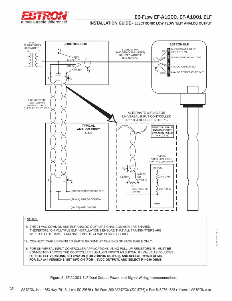
*1: THE 24 VAC COMMON AND ELF ANALOG OUTPUT SIGNAL COMMON ARE SHARED. THEREFORE, ON MULTIPLE ELF INSTALLATIONS ENSURE THAT ALL TRANSMITTERS ARE WIRED TO THE SAME TERMINALS ON THE 24 VAC POWER SOURCE.
*2: CONNECT CABLE DRAINS TO EARTH GROUND AT ONE END OF EACH CABLE ONLY.
*3: FOR UNIVERSAL INPUT CONTROLLER APPLICATIONS USING PULL-UP RESISTORS, R1 MUST BECONNECTED ACROSS THE CONTROLLER’S ANALOG INPUTS AS SHOWN. R1 VALUE AS FOLLOWS:FOR STD ELF VERSIONS, SET SW2 ON (FOR 2-10VDC OUTPUT), AND SELECT R1=500 OHMS.FOR ELF /A1 VERSIONS, SET SW2 ON (FOR 1-5VDC OUTPUT), AND SELECT R1=250 OHMS.
*2
*2 *2
*1
ANALOG TEMPERATURE OUTGREEN
GREEN
(BLACK)(WHITE) OR (GREEN)
+10 VDC
25 K-OHM
200 K-OHMR1(SEE NOTE *3)¼ W MIN
TYPICAL“UNIVERSAL INPUT “
CONTROLLER CIRCUIT
ALTERNATE WIRING FORUNIVERSAL INPUT CONTROLLER
APPLICATION (SEE NOTE *3)
SELECT R1 VALUE AND CONFIGURE
SW2 AS DETAILED IN NOTE *3.
*2
TYPICALANALOG INPUT
BAS
2 CONDUCTOR TWISTED PAIR
SHIELDED CABLESUPPLIED BY OTHERS
(BLACK) ANALOG COMMON
(WHITE) AIRFLOW OUT
(GREEN) TEMPERATURE OUT
*2
Figure 5. EF-A1001 ELF Dual Output Power and Signal Wiring Interconnections

IG_E
F-A1
00
0-T
_R1
A
a measurable difference!
®
EB-FLOW EF-A1000, EF-A1001 ELFINSTALLATION GUIDE - ELECTRONIC LOW FLOW ‘ELF’ ANALOG OUTPUT
EBTRON, Inc. 1663 Hwy. 701 S., Loris SC 29569 • Toll Free: 800.2EBTRON (232.8766) • Fax: 843.756.1838 • Internet: EBTRON.com 11
6. ELF INITIAL START UP / NORMAL OPERATIONThe following procedure is intended for initial start up of the instrument. Following the initial set up, no further user activ-ity is required during normal operation.
1. Remove the cover to the electronics enclosure by removing the four screws on the cover.
2. Make sure that the 24VAC circuit breaker used to power the ELF is turned OFF until all wiring is complete!
3. Confirm 24VAC connection from the power source to the ELF 24VAC wire (red wire) as outlined in the ELF 24VAC Power Connections section of this document.
4. Confirm common ground 24VAC and signal ground connection from the power source to the ELF at the black wire.
5. Confirm ELF analog airflow (and temperature for EF-A1001) signal output connections at the white wire (and greenwire for EF-A1001), to the analog input of the BAS as outlined in ELF Analog Output Connections section of this doc-ument. Note that the ground of the BAS must be at the same voltage reference as the ground of the ELF and thepower source.
6. Set the desired analog output options using CONFIG switches SW1 to SW4 as outlined in the ELF Analog OutputOption Switch Settings section of this document.
7. Activate the 24VAC power source to power on the ELF.
8. Following a brief instrument initialization, the green Activity LED will continuously flash ON for 1 second, then OFFfor 1 second. This indicates normal operation. In the event of a sensor fault, the LED will produce longer continu-ous flashes ON for 2 seconds, and OFF for 2 seconds.
9. Confirm that the BAS is receiving the analog output signals that indicate instrument airflow (or equivalent velocitypressure) and temperature.
10. Replace the ELF electronics enclosure cover and secure with the four screws removed in step 1.
6.1 Converting the Analog Airflow Output Signal from Linear to Volumetric flow - FPM to CFMThe analog airflow output can be converted from velocity (FPM) to an equivalent volumetric flow (CFM) by multiplying theindicated flow velocity by the free area of the sensor installed location (in square feet). For example, with the ELFinstalled in a 12 inch round duct, using the 0-10VDC scale and 3,000 FPM full scale output range options; an airflowoutput of 5VDC indicates a flow velocity of 1,500 FPM (5VDC is one-half of the 0-10VDC output, corresponding to half ofthe 0-3,000 FPM scale; and equals 1,500 FPM). The ELF installed duct location area in this example is calculated at0.785 ft2 (using Pi x duct radius2, or 3.14 x 0.5ft2). Multiplying the indicated instrument output of 1,500 FPM by the ductfree area of 0.785 ft2 yields an equivalent volumetric flow of 1,177.5 CFM.
7. ELF ADDITIONAL INFORMATIONRefer to the separate Installation, Operation and Maintenance Technical Manual TM_EF-A1000-D for additional informa-tion, or contact your local EBTRON representative or our Technical Support Team at 800.2EBTRON (1.800.232.8766).

IG_E
F-A1
00
0-T
_R1
A
a measurable difference!
®
EBTRON, Inc. 1663 Hwy. 701 S., Loris SC 29569 • Toll Free: 800.2EBTRON (232.8766) • Fax: 843.756.1838 • Internet: EBTRON.com