
INSTALLATION GUIDE AND USER’S MANUAL · INSTALLATION GUIDE AND USER’S MANUAL ... than no...
34
INSTALLATION GUIDE AND USER’S MANUAL Fastlane Pool
Transcript of INSTALLATION GUIDE AND USER’S MANUAL · INSTALLATION GUIDE AND USER’S MANUAL ... than no...

I N S T A L L A T I O N G U I D E A N D U S E R ’ S M A N U A L
Fastlane Pool

1
Endless Pools, Inc. provides for every aspect of a Fastlane Pool project. This manual assists in the installation process, as well as the general maintenance of your Fastlane Pool.
Additional available resources including the Planning Guide and selected Supplemental Guides are available to you. These documents are available online at www.myendlesspool.com/downloads.html. In addition, we encourage installers to call our Customer Service Department at (800) 910-2714 before beginning installation to register their projects and sign up for weekend technical support.
Please be advised that gloves and safety goggles should be worn during the installation of a Fastlane Pool.
Please take into consideration the following before proceeding:
If you have purchased the Optional Heater/Controller package, that will require a 3-wire (w/ neutral) 220v, 30 amp, GFCI power supply.
If you have purchased the standard package, than no neutral is required and the wire can be left unused.
Installation Instruction Booklet Information
Installation Instructions Table of Contents
Receiving the Fastlane Pool. . . . . . . . . . . . . . . . . . . . . . . . . 2
Pool Positioning . . . . . . . . . . . . . . . . . . . . . . . . . . . . . . . . . . 2
Ground Preparation . . . . . . . . . . . . . . . . . . . . . . . . . . . . . . . 3
Pool Assembly . . . . . . . . . . . . . . . . . . . . . . . . . . . . . . . . . . . 3
Fastlane Swim Unit Assembly . . . . . . . . . . . . . . . . . . . . . . . 5
Water Quality System . . . . . . . . . . . . . . . . . . . . . . . . . . . . . 7
Skimmer Assembly . . . . . . . . . . . . . . . . . . . . . . . . . . . . . . . 8
Connecting Skimmer/Suction Wall Fitting . . . . . . . . . . . . . 8
Connecting Return Wall Fitting . . . . . . . . . . . . . . . . . . . . . . 8
Drainage . . . . . . . . . . . . . . . . . . . . . . . . . . . . . . . . . . . . . . . . 9
Fastlane Hydraulic Power Unit Assembly . . . . . . . . . . . . . . 9
Bonding and Grounding. . . . . . . . . . . . . . . . . . . . . . . . . . . . 9
Hydraulic Fluid . . . . . . . . . . . . . . . . . . . . . . . . . . . . . . . . . . 9
Assembling the Water Quality System . . . . . . . . . . . . . . . 10
Fastlane Equipment Hutch Assembly . . . . . . . . . . . . . . . . 11
Electrical Requirements 60Hz . . . . . . . . . . . . . . . . . . . . . . 12
Electrical Requirements 50Hz . . . . . . . . . . . . . . . . . . . . . . 12
Heater Controller . . . . . . . . . . . . . . . . . . . . . . . . . . . . . . . . 13
Using the Fastlane Swim Unit . . . . . . . . . . . . . . . . . . . . . . 16
Installing the an Antenna Extension . . . . . . . . . . . . . . . . . 16
Caring for the Fastlane Pool . . . . . . . . . . . . . . . . . . . . . . . 16
Placarding the Fastlane Pool . . . . . . . . . . . . . . . . . . . . . . . 17
Retractable Security Cover Installation . . . . . . . . . . . . . . . 18
Installing the Ladder . . . . . . . . . . . . . . . . . . . . . . . . . . . . . 22
Installing the Cover . . . . . . . . . . . . . . . . . . . . . . . . . . . . . . 23
Outdoor Installations . . . . . . . . . . . . . . . . . . . . . . . . . . . . . 27
Wiring Schematic 60Hz . . . . . . . . . . . . . . . . . . . . . . . . . . . 30
Wiring Schematic 50Hz . . . . . . . . . . . . . . . . . . . . . . . . . . . 31
Fastlane Pool Warrantee. . . . . . . . . . . . . . . . . . . . . . . . . . . 32

RECEIVING THE FASTLANE POOL
The Fastlane Pool is shipped via UPS and contains at least 16 packages:
Box 1: Fastlane Pool Power Unit
Box 2: Biodegradable Vegetable Fluid
Box 3: Fastlane Pool Swim Unit Housing
Box 4: Fastlane Pool Swim Unit AccessoriesQty 2 - Hydraulic Hose Protective ChannelsQty 1 - Acrylic Top for Swim UnitQty 1 - Acrylic Hanging BracketQty 1 - Top BumperQty 1 - Lower StandoffQty 1 - Owner’s Manual Kit (Padded Envelope)
Qty 1 - Owner’s ManualQty 2 - Hydraulic Adapters (8 Female JIC x 6 Male JIC)Qty 1 - Fastlane Pool Bonding KitQty 36 - 3/4” 10-32 Machine ScrewsQty 10 - 1” 10-32 Machine ScrewsQty 4 - Rubber Grommets
Box 5: Fastlane Pool Swim Unit Base
Box 6: Fastlane Pool Liner Box (Only for a 9x13 Pool)Qty 1 - Pool LinerQty 2 - Vertical StrutsQty 4 - Top Corner TubesQty 4 - Bottom Corner Tubes
Box 6a (Only for a 9x17 Pool)Qty 1 - Pool LinerQty 4 - Vertical StrutsQty 4 - Top Corner TubesQty 4 - Lower Corner TubesQty 2 - 120cm Top Straight Tubes Qty 2 - 120cm Bottom Tubes
Box 7: Fastlane Pool Strut BoxQty 8 - Vertical Struts
Box 8: Fastlane Pool Tube BoxQty 2 - 120cm Top Straight TubesQty 2 - 60cm Top Straight TubesQty 3 - 120cm Straight Bottom Tubes
Box 9: Fastlane Pool Tube BoxQty 2 - 120cm Top Straight TubesQty 2 - 60cm Top Straight TubesQty 3 - 120cm Straight Bottom Tubes
Box 10: Fastlane Pool Water Quality SystemQty 1 - 50sq ft Skim FilterQty 1 - Circulating PumpQty1 - Plumbing Parts bag
Qty 2 - Thru-wall FittingsQty 2 - MPT x Slip 90º Street ElbowsQty 2 - Slip x Slip UnionsQty 2 - Slip x Slip Ball ValvesQty 2 - Pump Unions with O-RingsQty 1 - Male Slip x Female Slip 90º Street ElbowQty 1 - MPT x Insert AdapterQty 1 - MPT x Insert 90º ElbowQty 2 - Plastic Hose ClampsQty 2 - Threaded Plug with O-RingQty 1 - Eyeball Fitting
Qty 1 - 4oz PVC CleanerQty 1 - 4oz PVC CementQty 1 - Teflon TapeQty 1 - Liquid Tite Electrical Fitting
Qty1 - Fastlane Pool Start Up BagQty 1 - Container of Test StripsQty 1 - Water ClarifierQty 1 - pH IncreaserQty 1 - pH DecreaserQty 1 - Vinyl CleanerQty 1 - Bag of ShockQty 1 - Nature 2 Purifying Cartridge
Box 11: Fastlane Pool Skim Filter Housing AssemblQty 1 - Skim Filter HousingQty 2 - Large Bent TabsQty 2 - Small Bent TabsQty 10 - 1/2” 10-32 Stainless Steel Machine ScrewsQty 5 - 1” Self Tapping Stainless Steel ScrewsQty 1 - 11/64” Drill BitQty 1 - 3’ Length of Suction Hose
Box 12: Fastlane Pool Equipment HutchQty 1 - Equipment Hutch Qty 1 - Equipment Mounting BoardQty 1 - Pump Mounting Clamp
Box 13: 50’ Roll of Flexible PVC
Box 14: Fastlane Pool Ladder
Box 15: Solar cover
Box 16: Optional Heater ControllerQty1 - Heater ControllerQty1 - Keypad for Heater ControllerQty2 - Heater Tail Piece Qty2 - Heater Tail Piece T GasketsQty1 - Slip x Slip 90º ElbowQty1 - Male Slip x Female Slip 90º Street ElbowQty1 - 6-1/2” PVC NippleQty1 - 4-1/4” PVC NippleQty1 - Heater Controller Mounting ClampQty4 - 3/4” 10-32 Machine ScrewQty4 - 10-32 KEP Nut
POOL POSITIONING
To ensure ideal operation of the Fastlane Pool, consider the fol-lowing steps when selecting a location for the pool.
• Look for an area that receives maximum sunlight for increasedheat and extended use.
• Find a location with minimal wind exposure to minimize heat loss.
• Be aware of the amount of trees and shrubbery around the poolto limit the amount of debris that may accumulate in the pool.
• Select a location with accessibility to water and electric sources.
• Consider privacy when selecting a location.
2

GROUND PREPARATION
The surface the Fastlane Pool is to be assembled on must be firmand level. The Fastlane Pool must be installed as level as possi-ble, within 2"- 3" of level (from the highest point to the lowestpoint of the pool). If the pool will be assembled on a sloping sur-face, be sure to install the skimmer on the lower side to ensure thatit will not suck air into the pump. If the ground is not level and itis desired to make a more level surface, take the earth from thehigh area of the uneven surface; do not add earth to the low areaof the surface. Once the surface is level, clear any debris or sharpobjects that may be uncomfortable to walk on or could become apuncture hazard for the liner. Foam flooring may be added underthe liner for additional comfort.
The pool is comprised of various parts. Therefore, before pro-ceeding with installation, ensure that all necessary parts for thepool are present and group like parts together.
Part Description Quantity(A) Liner 1(B) Top 130cm straight tubes (wider) 6 (8 for Longer Pool)(C) Top 60cm straight tubes (wider) 4(D) Top corner tubes (wider) 4(E) Bottom corner tubes (thinner) 4(F) Straight bottom tubes (thinner) 6 (8 for Longer Pools)(G) Struts 10 (12 for Longer Pools)
The supporting legs, or struts (Part G), support much of the weightof the Fastlane Pool and may need additional support in “softground” installations, or in areas that may experience excessground water. A 2"x 8" x 22" piece of lumber installed under eachstrut’s base and leveled with the ground is very effective. Makesure the entire base of each strut is on the 2" x 8" lumber as anyover-hang may result in bending of the strut. A concrete slab ofthe similar dimensions may be used as well. Please note that anysupport(s) added under the pool structure must be recessed so thatthe top of the support is level with the ground surface. Lifting thestruts or frame in any manner may cause excessive stress on theliner and frame, and may void the Fastlane Pool warranty. (Referto Diagram #1: Supporting Legs / Struts.)
DIAGRAM #1: SUPPORTING LEGS / STRUTS
POOL ASSEMBLY
1. Unfold and spread out liner (Part A) on the prepared area.NOTE: Keep in mind the desired “swim direction” when positioning the liner, because when the Fastlane Pool is fully assembled, the swim direction will be headed towardsthe end of the pool that has the pre-cut holes. These holes arefor the water quality thru-wall fittings and hydraulic hoses.
2. Align the struts (Part G) with the prepared cut outs at top of liner.
3. Connect bottom tubes (Part F) to struts (Part G) one at a time tomake the four sides of the pool. Connect corner tubes (Part E) tothe open ends of both struts to finish each of the four corners.
A
B
C
DEF
G
3

4. Connect the top tubes (Parts B and C) together. NOTE: Theshorter tube (Part C) is always the last tube on the rightwhen facing the pool wall. (Refer to Diagram #2: WiderStraight Tube Layout.)
DIAGRAM #2:WIDER STRAIGHT TUBE LAYOUT
5. Feed the connected top tubes (Parts B and C) into the corresponding sleeves of the liner. Be sure to align the top tubeslots with the matching cutouts in the liner, and then insert thecorresponding struts (Part G) into the top tube slots.
Longer (9' x 17') Fastlane Pool
Standard (9' x 13') Fastlane Pool
4
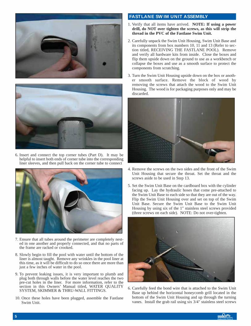
6. Insert and connect the top corner tubes (Part D). It may behelpful to insert both ends of corner tube into the correspondingliner sleeves, and then pull back on the corner tube to connect
one end at a time to the top rails (Parts B and C).
7. Ensure that all tubes around the perimeter are completely nest-ed in one another and properly connected, and that no parts ofthe frame are racked or crooked.
8. Slowly begin to fill the pool with water until the bottom of theliner is almost taught. Remove any wrinkles in the pool liner atthis time, as it will be difficult to do so once there are more thanjust a few inches of water in the pool.
9. To prevent leaking issues, it is very important to plumb andplug both through walls before the water level reaches the twopre-cut holes in the liner. For more information, refer to thesection in this Owners’ Manual titled, WATER QUALITYSYSTEM, SKIMMER & THRU-WALL FITTINGS.
10. Once these holes have been plugged, assemble the FastlaneSwim Unit.
FASTLANE SWIM UNIT ASSEMBLY
1. Verify that all items have arrived. NOTE: If using a powerdrill, do NOT over tighten the screws, as this will strip thethread in the PVC of the Fastlane Swim Unit.
2. Carefully unpack the Swim Unit Housing, Swim Unit Base andits components from box numbers 10, 11 and 13 (Refer to sec-tion titled, RECEIVING THE FASTLANE POOL). Removeand verify all hardware kits from inside. Close the boxes andflip them upside down on the ground to use as a workbench orcollapse the boxes and use as a smooth surface to protect thecomponents from scratching.
3. Turn the Swim Unit Housing upside down on the box or anoth-er smooth surface. Remove the block of wood by removing the screws that attach the wood to the Swim UnitHousing. The wood is for packaging purposes only and may bediscarded.
4. Remove the screws on the two sides and the front of the SwimUnit Housing that secure the throat. Set the throat and thescrews aside to be used in Step 13.
5. Set the Swim Unit Base on the cardboard box with the cylinderfacing up. Lay the hydraulic hoses that come pre-attached tothe Swim Unit Base to each side so that they are out of the way.Flip the Swim Unit Housing over and set on top of the SwimUnit Base. Secure the Swim Unit Base to the Swim UnitHousing by using six of the 1" stainless steel screws provided(three screws on each side). NOTE: Do not over-tighten.
6. Carefully feed the bond wire that is attached to the Swim UnitBase up behind the horizontal honeycomb grill located in thebottom of the Swim Unit Housing and up through the turningvanes. Install the grab rail using six 3/4" stainless steel screws
5

6
and the six 10-32 stainless steel lock nuts provided. Secure thebond wire that has been fed up through the turning vanes underone of the six screws. Secure the other bond wire that has beenpre-installed in the Swim Unit Housing under a second screw inthe grab rail. NOTE: Do not over-tighten.
7. Run the hydraulic hose up the back of the Swim Unit Housingso that the PVC hydraulic hose protective channel will cover thehose. Firmly secure but do NOT over tighten the eight stain-less screws per channel. Repeat for the second hose.
8. Once both protective channels are attached, pull the twohydraulic hoses tight and secure them to the top of the SwimUnit Housing using the green hose clamps provided. To accom-plish this, unscrew the green hose clamps, insert the hoses, and re-screw the clamps snugly into the top of the Swim Unit Housing. Feed the bond wire (from Step 6) to the back of the Swim Unit Housing along one of thehydraulic hoses.
9. Attach the acrylic hanging bracket to the back of the Swim UnitHousing with four of the 3/4" stainless steel screws. NOTE: Donot over-tighten. Leave the two top screw holes unused.
10. Attach the top bumper piece (length of PVC pipe) to the SwimUnit Housing through the unused screw holes (top holes fromStep 9) in the acrylic hanging bracket using two of the ten 1”stainless steel screws. NOTE: Do not over-tighten.
11. Attach the lower extension bumper to the rear of the SwimUnit Base using two 3/4" stainless steel screws. NOTE: Donot over-tighten.
12. Attach the wheels to the Swim Unit base. Slide the axle throughthe two holes that are marked in yellow on the intake grill in theSwim Unit base. These holes have been widened to allow theaxle to pass through freely. There are a total of four large andtwo small washers used in the wheel assembly. Be sure that twolarge washers are located between each wheel and the intakegrill. Secure the wheels to the axle with one smaller washerbetween the screw and the wheel on both sides.

13. Re-install the throat that was removed previously in Step 4.
14. Place the Swim Unit on the ground and roll it close to theFastlane Pool location for installation. Be careful not to tipover the Swim Unit, as it is front-heavy.
15. Once the pool is nearly full and the liner is taught and wrin-kle-free, carefully lift the assembled Fastlane Swim Unit intothe pool at the skimmer end. Lower and position the SwimUnit so that the acrylic hanger “clips” on to the top straighttube (Part B) as shown in Step 18. The Swim Unit should becentered along the end of the pool.
16. The hydraulic hoses can be simply left hanging over the top ofthe pool wall to run back to the Power Unit, or they can be fedthrough the pool wall as described in Steps 17 & 18. Attachthe bond wire to the nearest supporting strut (Part G) using theprovided self-drilling / self-tapping screw to bond the SwimUnit to the pool’s structural frame.
(NOTE: Steps 17 & 18 are optional, skip to Step 19 if choosingnot to feed hoses through the pool wall)
17. If a more finished look is desired, four rubber grommets havebeen provided to fit into holes that can be cut into the topwhite section of the liner. Once the Fastlane Swim Unit hasbeen properly placed in the pool and is centered along thewidth of the pool, locate the holes through which the hydrauliclines will run. Using a permanent marker (while outside thepool and along the exposed side of the acrylic hanger), dot theliner with two marks, each being 1-1/2” away from the verti-cal edges of the hanger (away from center) and 3” down fromthe top of the pool. Place a rubber grommet over the marks sothat they are centered in the grommet openings. Trace theINSIDE of the grommets onto the liner. Using a utility knifewith a sharp blade, SLOWLY and CAREFULLY cut out thetraced circles. Refer to photo in Step 18 to verify hole loca-tion before cutting. NOTE: Cutting small curves or a circlewith a utility knife can be difficult. It may be best to work inmany small straight cuts for accuracy.
18. Push the grommets into the holes so that the fabric edges tuckinside the grooves of the grommets. Repeat this process againfor two more holes inside the pool. NOTE: When complete,the hydraulic hoses and bonding wire will be passing throughtwo layers of fabric. It is important to feed the hydraulic hosesand bonding wire through both grommets, starting from insidethe pool and then feeding them through the outer layer of fab-ric as shown in the photo below.
19. Install the top cover of the Swim Unit Housing using six 3/4”stainless steel screws (three screws on each side).
20. Run the hydraulic hoses back to the Hydraulic Power Unit.Using the provided bonding lug and self-drilling / self-tappingscrew, fasten the bonding lug to the bottom of the same strutused in Step 16 (when the Fastlane Swim Unit was bonded tothe pool’s structural frame). To bond the Fastlane Swim Unitand Fastlane Pool structure to the rest of the pool equipment,run a #8 AWG bare copper wire from the bonding lug (thatwas just attached) to the rest of the Water Quality Systemequipment and Hydraulic Power Unit. Always be sure to ver-ify any additional bonding requirements that may be dictatedby local codes and ordinances.
WATER QUALITY SYSTEM, SKIMMER & THRU-WALL FITTINGS
Plumbing and Start-up Kit (See section titled, RECEIVING THEFASTLANE POOL, Box #10)
Qty 1 4oz Container of PVC Cleaner
Qty 1 4oz Container of PVC Cement
Qty 2 Pump Union with 1-1/2" Adapter with O-Ring
Qty 1 Male Slip x Female Slip 1-1/2" 90º Street Elbow
Qty 2 Female Slip x Female Slip Ball Valve
Qty 2 Female Slip x Female Slip Union
Qty 2 Male Pipe Thread x Female Slip 90º Street Elbow
Qty 1 1-1/2" Eyeball Fitting
Qty 2 1-1/2" Threaded Plugs with O-Ring
Qty 1 1-1/2" Male Pipe Thread x Insert 90º Elbow
Qty 1 1-1/2" Male Pipe Thread x Insert Adapter
Qty 1 3' Length of Flexible Hose
Qty 2 1-1/2" PVC Thru-Wall Fitting Female Thread (inside) xFemale Thread (outside)
Additional Tools Required• Tape measure• Hack saw
7

8
SKIMMER ASSEMBLY
1. Align the skimmer opening with the opening in the housing.Use the hardware provided with the skimmer to attach theskimmer to the housing. Make sure to use the skimmer face-plate when attaching the skimmer.
2. Attach the skimmer body to the skimmer housing. Align the 2smaller tabs to the underside of the holes in the top of the hous-ing. The long face of the small tab should be aligned with thecircular opening in the housing. Use the provided machinescrew to attach the small tab to the housing.
3. Once the skimmer is attached to the housing through the open-ing, use the provided drill bit to drill a hole into the skimmerthrough the hole in the small tab. Thread in a short machinescrew into each hole, securing the skimmer to the small tabs.
4. Place the larger tab’s smaller face onto the underside of the out-side of the housing so that the pre-drilled holes are aligned. Usethe provided sheet metal screws to attach the larger tabs to thehousing.
5. Once the skimmer assembly is complete, place it inside the poolin the same corner as the lower thru-wall fitting. (front right)
6. Use the provided drill bit and self-tapping screws to attach theskimmer assembly to the top tube of the pool. Position the holesin the larger tab with the center of the tube. Drill through theliner and tube with the drill bit. and then secure the assembly tothe top tubes with the four self tapping screws.
CONNECTING SKIMMER / SUCTION WALL FITTING
(Refer to Diagram #3: Skimmer / Suction Thru-Wall Diagram)
• Push fitting (#4) through the wall of the pool from the inside.MAKE SURE TO USE A GASKET (#5) on both sides of thewall of the pool. Place the cork ring next to the gasket outsidethe pool and secure the wall-fitting nut (#7) to (#4) now stickingthrough the pool wall. Tighten with a large pair of channel locks.Make sure the nut is very snug but do not over-tighten, as thismay crack the fitting.
• Thread the union and insert adaptor (#1) into the bottom of theskimmer. NOTE: No glue or tape is necessary to complete thisstep.
• Inside the pool, thread the insert elbow (#3) into the thru-wall (#4).
• Wrap a small amount of Teflon tape around the end of the adaptor.
• Press the flexible hose (#2) onto each of these fittings. Use theprovided plastic hose clamps to attach.
• Outside the pool, thread in the male portion of the street ell (#8)into the tailpiece of the thru-wall fitting (#4).
• When the water quality system equipment needs maintenance,the insert elbow fitting (#3) should be removed and the provid-ed plug should be threaded into the thru-wall fitting (#4) to pre-vent the pool from draining.
DIAGRAM #3: SKIMMER / SUCTION THRU-WALL DIAGRAM
CONNECTING RETURN WALL FITTING
(Refer to Diagram #4: Return Wall Fitting Diagram)
• Push fitting (#8) through the wall of the pool from the inside.MAKE SURE TO USE A GASKET (#9) on both sides of thewall of the pool. Place the cork ring next to the gasket outsidethe pool and secure the wall-fitting nut (#10) to (#8) now stick-ing through the pool wall. Tighten with a large pair of channellocks. Make sure the nut is very snug but do not over-tighten, asthis may crack the fitting.
3
1
45578
2
6
Glue Pipe From PUMP
Do Not Glue
Skimmer
Pool Wall
Thru-Wall

• Outside the pool, thread in the male portion of the street elbow(#6) into the tailpiece of the thru-wall fitting (#8).
• From inside the pool, thread the eyeball fitting into the thru-wallfitting (#8). Point the eyeball towards the bottom of the pool foroptimal water circulation in the Fastlane Pool.
• When the water quality system equipment needs maintenance,the eyeball fitting should be removed and the provided plugshould be threaded into the thru-wall fitting (#8) to prevent thepool from draining.
DIAGRAM #4: RETURN WALL FITTING DIAGRAM
DRAINAGE
Drainage needs to be provided around the pool and near the waterquality equipment. It is important to be prepared in the unlikelyevent of a leak. If operating the Fastlane Pool indoors, it is ideal toinstall floor drains in the area around the pool’s perimeter, but notdirectly under the pool. It is worth the time and effort now to installa drainage system rather than be unprepared in the event of a mishap.
FASTLANE HYDRAULIC POWER UNIT ASSEMBLY
The power unit should placed on flat and level surface. Whetherplaced indoors or outdoors, this is an air-cooled unit and must haveample ventilation. Therefore, a minimum of 12" of air spaced mustbe provided on all sides of the power unit. In addition, the powerunit needs to be check periodically for maintenance and should beaccessible.
The power unit is heavy, care should be taken when placing the power unit.
Once the power unit is in place, connect the run hoses. The lowpressure hose, which will have red tape, gets connected to the con-nection on the black fill cap. The high pressure hose gets connectedto the fitting on the high pressure manifold.
Make sure that the power is turned off to the power unit. Removethe fill black fill cap and remove the oil filter by lifting it out of fillopening. Use the provided paper funnels and fill the reservoir towith in 2" of the top. Once filled, replace the oil filter and ensurethat it is seated properly before putting the fill cap back on. If youhave selected a longer run hose, we have provided extra fluid. Inthis case, turn the unit on and let it run for one minute to fill the runhoses. Turn the power off, remove the fill cap and oil filter, and addfluid as needed. Again, you want to fill the reservoir to within 2" ofthe top.
The power unit controller comes equipped with an automatic timershutting off the system 30 minutes after receiving its last command.Because the controller "remembers" the last speed at which isturned off, it will return to that same pace when it is turned back on.
BONDING AND GROUNDING
All of the electrical equipment that we supply is UL or CSA approvedand must be installed in accordance with local electric codes by alicensed local electrician. Bonding and Grounding is an importantpart of that process. All electrical components have bonding lugs andshould be bonded together and to the steel pool panels. A bondingconductor shall be solid copper not smaller than 8 AWG and may beinsulated, covered or bare. If new construction is involved where rein-forcing rods are installed in the concrete under or adjacent to the poolthis should be included in the bonding circuit. Each of the pieces ofequipment should be separately grounded.
A #8AWG bare copper wire is required for all bonding connections.Connect this wire to your power unit and run it, with your hydraulichose and whip, to the front of the pool. Inside the bonding kit therewill be a machine screw and nut, a bonding lug, and a drill bit. Feedthe bonding wire through the bonding lug vertical strut at the frontof the pool. Connect the Fastlane stainless steel bond wire and thebare copper wire to this bonding lug.
HYDRAULIC FLUID
Fill the reservoir on the Power Unit no more than 2" from the top ofthe reservoir. Endless Pools, Inc. supplies a special non-petroleumfluid created for this application and this equipment. Do not use asubstitute hydraulic fluid. Extra hydraulic fluid is provided for longerhose runs. Any excess fluid should be retained for future use.
Make sure that all hydraulic connections are tight, then press the ONbutton on the remote to turn on the Power Unit. Run for a minute ortwo then check for hydraulic leaks at the Power Unit and the pool andtighten if necessary. By pressing the OFF button on the remote youcan turn off the Power Unit. Make sure you can do this.
ASSEMBLING THE WATER QUALITY SYSTEMWITHOUT HEATER CONTROLLER
Loosely attach the circulating pump to the power unit. The pumpwill be attached to the handle of the power unit on the same sideas the hydraulic connections. Place the circulating pump on to thepower unit so that the suction of the circulating pump is facingout. Place the pump foot clamp on the underside of the power unithandle, aligning the holes in the pump foot clamp to the holes in
LowPressureFitting
HighPressureFitting
89
2
Pool Wall
9106
Glue Pipe From PUMP
Thru-Wall
9
Fill Cap

the pump foot. Use the provided screws to clamp the pump on thepower unit handle.
Attach the pump union nuts to both fittings of the pump. Makesure that the o-rings are in place before attaching the union fit-tings. Glue a male slip x female slip street elbow into the pressurefitting of the pump so that it is facing away from the power unit.Cut two 2-1/2” lengths of flexible PVC off of the 50’ roll of flex-ible PVC that was provided. Glue one of these lengths into theunion fitting connected to the suction side of the pump. Glue theother length of 2-1/2” PVC into the elbow that is connected to thepressure union. Next glue a slip x slip ball valve onto each of the2-1/2” lengths of flexible PVC. Finally, cut the 50’ length downto the appropriate lengths to connect the suction side of the pumpto the skimmer thru-wall assembly and connect the pressure sideof the pump to the return thru-wall assembly.
ASSEMBLING THE WATER QUALITY SYSTEMWITH HEATER CONTROLLER
Note: Additional PVC fittings can be found in the HeaterController box. Loosely attach the circulating pump to the powerunit. The pump will be attached to the handle of the power uniton the same side as the hydraulic connections. Place the circulat-ing pump onto the power unit so that the suction of the circulatingpump is facing out. Place the pump foot clamp onto the undersideof the power unit handle, aligning the holes in the pump footclamp to holes in the pump foot. Use the provided screws toclamp the pump to the power unit handle.
Next remove the two reservoir mounting bolts on the side oppo-site the power unit controller. Align the holes in the heater con-troller mounting board with holes in the power unit that were justremoved. Replace the bolts and tighten securely.
Then place the heater controller-mounting clamp onto the mount-ing board so that they are aligned with the holes closest to thepower unit. The tabs of the mounting clamp should be facing awayfrom the power unit. There should also be a gap between the taband the spacer. Use the provided hardware to attach the mountingclamp to the mounting board. DO NOT install screws into thefront holes at this time.
Now slide the heater controller into position, so that the plug-inports are facing away from the power unit and the feet of theheater controller are seated firmly under the mounting clamp.Once the heater controller is in place, use the provided nut andmachine screws to attach the Heater/Controller to the mountingboard.
Pre-cut lengths of PVC have been provided. Apply PVC cleanerto both faces of the joint prior to gluing for every glue joint. Takethe 6-1/2” long piece of pipe and glue the female end of a maleslip x female slip elbow (street elbow) onto one end and glue apump union onto the other. Make sure that the union nut is in placeprior to gluing. Finally, glue a heater controller union half ontothe male end of the street elbow. Once this assembly has beenglued together, connect the pump to the heater controller. Makesure that there is an o-ring between the pump union and the pumpdischarge and there is a T-Gasket between the heater controllerunion nut and the union half.
10
Suction
Pressure
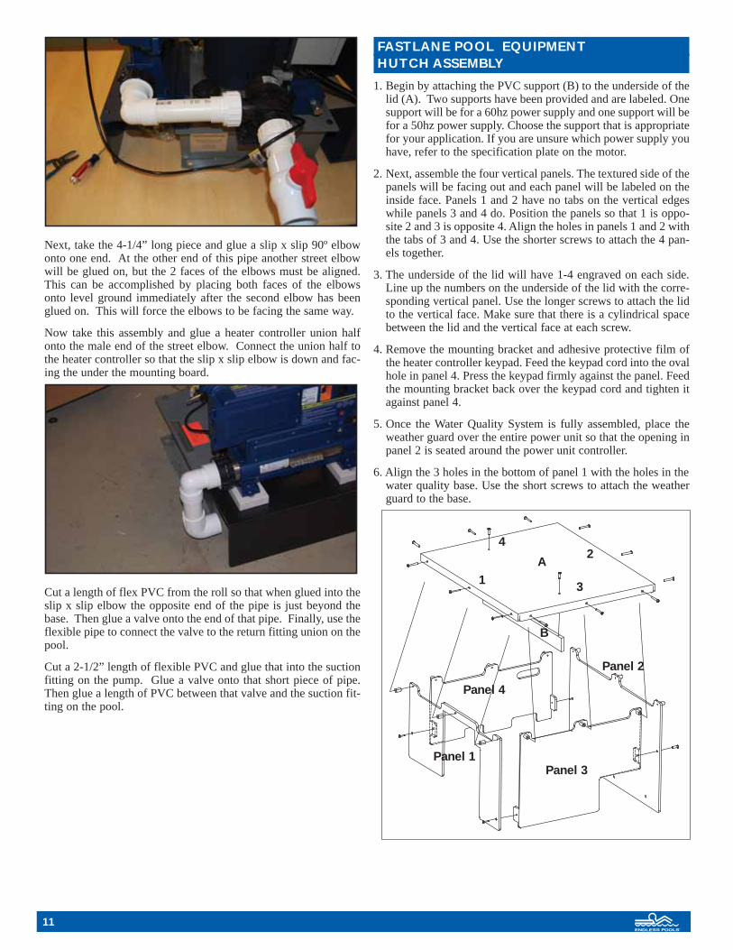
Next, take the 4-1/4” long piece and glue a slip x slip 90º elbowonto one end. At the other end of this pipe another street elbowwill be glued on, but the 2 faces of the elbows must be aligned.This can be accomplished by placing both faces of the elbowsonto level ground immediately after the second elbow has beenglued on. This will force the elbows to be facing the same way.
Now take this assembly and glue a heater controller union halfonto the male end of the street elbow. Connect the union half tothe heater controller so that the slip x slip elbow is down and fac-ing the under the mounting board.
Cut a length of flex PVC from the roll so that when glued into theslip x slip elbow the opposite end of the pipe is just beyond thebase. Then glue a valve onto the end of that pipe. Finally, use theflexible pipe to connect the valve to the return fitting union on thepool.
Cut a 2-1/2” length of flexible PVC and glue that into the suctionfitting on the pump. Glue a valve onto that short piece of pipe.Then glue a length of PVC between that valve and the suction fit-ting on the pool.
FASTLANE POOL EQUIPMENT HUTCH ASSEMBLY
1. Begin by attaching the PVC support (B) to the underside of thelid (A). Two supports have been provided and are labeled. Onesupport will be for a 60hz power supply and one support will befor a 50hz power supply. Choose the support that is appropriatefor your application. If you are unsure which power supply youhave, refer to the specification plate on the motor.
2. Next, assemble the four vertical panels. The textured side of thepanels will be facing out and each panel will be labeled on theinside face. Panels 1 and 2 have no tabs on the vertical edgeswhile panels 3 and 4 do. Position the panels so that 1 is oppo-site 2 and 3 is opposite 4. Align the holes in panels 1 and 2 withthe tabs of 3 and 4. Use the shorter screws to attach the 4 pan-els together.
3. The underside of the lid will have 1-4 engraved on each side.Line up the numbers on the underside of the lid with the corre-sponding vertical panel. Use the longer screws to attach the lidto the vertical face. Make sure that there is a cylindrical spacebetween the lid and the vertical face at each screw.
4. Remove the mounting bracket and adhesive protective film ofthe heater controller keypad. Feed the keypad cord into the ovalhole in panel 4. Press the keypad firmly against the panel. Feedthe mounting bracket back over the keypad cord and tighten itagainst panel 4.
5. Once the Water Quality System is fully assembled, place theweather guard over the entire power unit so that the opening inpanel 2 is seated around the power unit controller.
6. Align the 3 holes in the bottom of panel 1 with the holes in thewater quality base. Use the short screws to attach the weatherguard to the base.
11
A
B
1
24
3
Panel 1Panel 3
Panel 4
Panel 2

12
ELECTRICAL REQUIREMENTS AND CONNECTIONS (60Hz)
Consider the electrical requirements for the specific installationbefore locating the Water Quality System and gluing the plumb-ing parts. Different option packages require different plumbingand electrical configurations.
Standard Fastlane Pool package with no heaterA licensed electrician should make all electrical connections. Thestandard package will require a two-wire (plus ground) 220 volt30 amp GFCI Power Supply. The power unit controller mayhave to be attached to the power unit. If not done so already, con-nect the power unit as directed. There are two electrical whipsattached to the controller. The shorter one needs to be connectedto the power unit motor. The longer whip is going to be pre-wired into the LINE side of the contractor in the controller, whichwill then need to be connected to the incoming power supply. Thewhite wire in the long whip will be unused in this application.
Please refer to the following step-by-step instruction for supply-ing power to the circulating pump.
1. Cut the plug of the cord and strip back and expose the 3 wires.
2. Remove one of the unused 1/2” knockouts in the bottom of theController Box that is attached to the Hydraulic Power Unit.Slide the liquid tight fitting over the cord of the WQS pumpwith the compression nut end first. With the liquid tight fittingstill loose on the cord, push the threaded end of the fitting intothat hole in the Controller Box and determine the length ofcord that will need to feed into the box.
3. When the correct length is determined, tighten the compressionnut on the cord. Then feed the locknut over the cord and threadthe locknut onto the fitting to securely affix it to the ControllerBox.
4. On the contactor located inside the Controller Box, attach theWQS pump’s cord to the LOAD side of the contactor. Theblack wire goes to terminal R1, the white wire goes to terminalR3, and the green wire goes to the ground bus bar on the bot-tom of the Controller Box.
Fastlane Pool package w/ Optional Heater ControllerA licensed electrician should make all electrical connections.This option will require a three-wire (plus ground) 220 volt 30amp GFCI Power Supply. The power unit controller may have tobe attached to the power unit. If not done so already, connect thepower unit as directed. There are two electrical whips attached tothe controller. The shorter one needs to be connected to thepower unit motor. The longer whip is going to be pre-wired intothe LINE side of the contractor in the controller, which will thenneed to be connected to the incoming power supply. The whitewire will need to be connected to the load neutral of the 30ampGFCI breaker (the neutral pigtail needs to be connected to theneutral bus bar inside your breaker panel). A third electrical whipwill be provided with the heater controller. That will be wiredinto the contactor as well. The WQS pump and heater controllerwill only run when the swim current is not in use, but the keypadwill always have power.
Please refer to the following step-by-step instruction for supply-ing power to the heater controller:
1. Power is supplied to the system by connecting the existingwhip on the power unit control box to the shut off installed byyour electrician.
2. Connect the whip, provided with the heater controller, betweenthe unused knockout in the power unit controller and theknockout in the top left of the heater controller.
3. Inside the heater controller, connect the black wire to terminalL1, connect the red wire to terminal L2, connect the white wireto terminal N, and connect the green to terminal B. All fourterminals will be color-coded.
4. Inside the power unit controller, connect the four wires comingfrom the heater controller to the contactor as follows: connectthe black wire to terminal R2 (top left), connect the red wire toterminal R3 (bottom right), connect the green wire to theground bus bar at the bottom of the control box, and connectthe white wire to other white wire that is coming from theincoming power supply.
5. Plug the circulating pump into the CP port on the heater controller.
Wiring diagrams are available at the back of this book.
Fastlane Pool Package with optional 55,000 BTU Gas orPropane Heaters
A licensed electrician should make all electrical connections. Thestandard package will require a two-wire (plus ground) 220 volt30 amp GFCI Power Supply. The power unit controller mayhave to be attached to the power unit. If not done so already, con-nect the power unit as directed. There are two electrical whipsattached to the controller. The shorter one needs to be connectedto the power unit motor. The longer whip is going to be pre-wiredinto the LINE side of the contractor in the controller, which willthen need to be connected to the incoming power supply. Thewhite wire in the long whip will be unused in this application.Power will be supplied for both the circulating pump and theheater from the LOAD side of the contactor in the power unitcontroller. Endless Pools does not provide an electrical connec-tion between the power unit and the heater; these need to be pro-vided locally. In this application, the heater and circulating pumpwill be shut off when the swim current is on.
Please refer to the following step-by-step instruction for supply-ing power to the heater and circulating pump:
1. A two-wire 10AWG (plus ground) connection will need to bemade between the power unit controller and the heater.
2. Inside the power unit controller, connect the one wire to termi-nal R1, connect the other wire to terminal R3, and connect theground wire to the bus bar at the bottom of the controller.
3. The other end of this connection must terminate inside a junc-tion box that is attached to the electrical knockout of the heater.
4. Make sure that the heater’s transformer is wired for 220 volts.See the heater’s owner’s manual for more information.
5. Cut off the plug off of the circulating pump cord, expose thethree wires inside and strip back each individual wire. Havethis cord terminate inside the junction box that was connectedto the heater in step 3.
6. Under one wire nut, connect all 3 ground wires (green) fromthe heater, the pump, and the connection from the power unitcontroller.
7. Under one wire nut, connect one leg of the incoming power to one of the wires from the heater and one of the wires fromthe pump. Under another wire nut connect the three remain-ing wires.

ELECTRICAL REQUIREMENTS (50Hz)
Fastlane Pool without Heater Wiring InstructionsA licensed electrician should make all electrical connections. Thestandard package will require a two-wire (plus ground) 220 volt 30amp RCD Power Supply. The power unit controller may have to beattached to the power unit. If not done so already, connect the powerunit as directed. There are two electrical whips attached to the con-troller. The shorter one needs to be connected to the power unitmotor. The longer whip is going to be pre-wired into the LINE sideof the contractor in the controller, which will then need to be con-nected to the incoming power supply. The white wire in the longwhip will be unused in this application.
Please refer to the following step-by-step instruction for supplyingpower to the circulating pump.
1. Cut the plug of the cord and strip back and expose the 3 wires.
2. Remove one of the unused 1/2” knockouts in the bottom of theController Box that is attached to the Hydraulic Power Unit.Slide the liquid tight fitting over the cord of the WQS pump withthe compression nut end first. With the liquid tight fitting stillloose on the cord, push the threaded end of the fitting into thathole in the Controller Box and determine the length of cord thatwill need to feed into the box.
3. When the correct length is determined, tighten the compressionnut on the cord. Then feed the locknut over the cord and threadthe locknut onto the fitting to securely affix it to the ControllerBox.
4. On the contactor located inside the Controller Box, attach theWQS pump’s cord to the LOAD side of the contactor. The blackwire goes to terminal R1, the white wire goes to terminal R3, andthe green wire goes to the ground bus bar on the bottom of theController Box.
Fastlane Pool with Heater Wiring InstructionsTwo 220v 30amp RCD rated circuits are required when the option-al electric heater has been selected. A minimum of 10AWG wireshould be used for all field wiring. All connections should be madeby a licensed electrician.
We recommend that you have your electrician install two shutoffswithin 5’ of where you intend to place your power unit and waterquality system. These shutoffs can be installed prior to your poolbeing delivered. Please consult all appropriate national and localcodes.
The power unit controller may have to be attached to the power unit.If not done so already, connect the power unit as directed. There aretwo electrical whips attached to the controller. The shorter oneneeds to be connected to the power unit motor. The longer whip isgoing to be pre-wired into the LINE side of the contractor in thecontroller, which will then need to be connected to the incomingpower supply. Power to the heater controller is supplied by the sec-ond shut off and the heater-controller through the appropriateknockouts in these respective units. Inside the heater-controller,connect your live wire to terminal L1 (leaving the jumper wirebetween L1 and L2 in place), connect your neutral to terminal N,and connect your earth to terminal G. The circulating pump getsplugged into the green terminal labeled CP on the heater controller.
Wiring diagrams are available at the back of this book.
HEATER CONTROLLER
Connections simply snap into appropriate color coded receptacles.
Keypad connection
C
98
Input wiring shown above
13

14
TYPICAL SETTINGS
Set Point : 59°F to 104°F / Factory set at 84°FFilter Cycle Duration: 0 to 24 hrs / Factory set at 24 hrsMax Set Point: 59°F to 104°F / Factory set at 104°FPurge Cycle Frequency: 1 to 4 times a day / Factory set at 4
KEYPAD DOESN’T SEEM TO WORK
If a keypad doesn’t seem to work:
• Verify keypad connections.• Replace keypad if problem is corrected.• Replace in.xe if problem is not corrected.
in.xe UL/CSA electrical specifications:
Input rating: 120/240 VAC
(2-phase required, with neutral) 48 A maximum, 60Hz. Software limited to 24A. Install on a 30A GFCI circuit.
Output ratings:
Output Voltage Current Typical Device
Out 1 120/240V 17FLA Pump 1Out 3 120/240V 0.8 A Circulation
Pump/BlowerOut 4 120/240V 1 A Ozone GeneratorOut 5 120/240V 5 A Audio/Video deviceL1 Light, 12VAC, 0.1 ACO Communications port *C1 Top side controller *
*CO: Comm.connector (in.stik).
heat.wav ratings:
Voltage: 120/240VAC
Current: 17A resistive (4 kW heater at 240V)
Frequency: 50 / 60 Hz
heat.wav heater flow rate:
Minimum of 18 GPM is required
Important:
• All low voltage accessories use + 5Vdc and/or + 12 Vdc.
• All low voltage accessories combined: 150 mA max, on + 12 Vdc.
GENERAL SPECIFICATIONS:
Environmental:
Operating temperature: -20°C (-4°F) to 60°C (140°F)
Storage temperature: -25°C (-13°F) to 85°C (185°F)
Humidity: up to 85% RH, non condensing
IPx5 level of waterproofing is conditional on 3 items:
• Both front covers (heater and input wiring) are closed and screwed shut.
• A waterproof strain-relief/bushing is used for the cable entryinto the pack.
• Any unused in.link connections (HC, LC, or low voltage) isplugged with the appropriate blank plug.
Mechanical:
Weight: 4.76 kg (10.5 lbs)
Dimensions (W x H x D):
Chassis: 441.5mm x 298.5mm x 129mm (17.38" x 11.75" x 5.1")
UL/CSA Standards:
UL 1563 Fifth Ed.
File: E182156
CSA No. 22.2 - 218.1-M89.
TUV Standards:
EN/IEC 60335 - 2 - 60EN55014-1EN55014-2EN61000-3-2EN61000-3-3
The in.xe is lab tested to IPx5 enclosure protection levels.
in.k200 full-function keypad
The Quick Reference Card provides a quick overview of yourspa’s main functions and the operations accessible with your dig-ital control pad.
Spa Functions
Up/Down Keys
Use Up or Down key to setdesired water temperature. The temperature settingwill be displayed for 5 seconds
to confirm your new selection.
The “Set Point” icon indicates that the display shows the desired temperature, NOT the current water temperature!
98
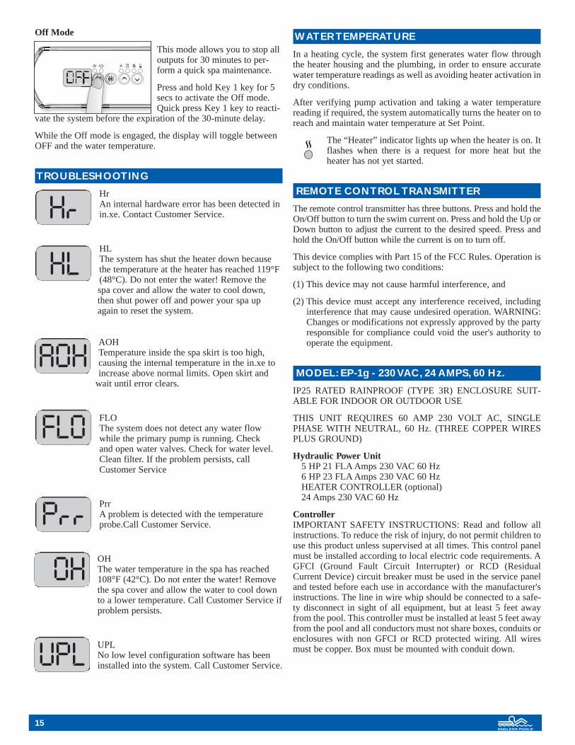
Off Mode
This mode allows you to stop alloutputs for 30 minutes to per-form a quick spa maintenance.
Press and hold Key 1 key for 5secs to activate the Off mode.Quick press Key 1 key to reacti-
vate the system before the expiration of the 30-minute delay.
While the Off mode is engaged, the display will toggle betweenOFF and the water temperature.
TROUBLESHOOTING
HrAn internal hardware error has been detected inin.xe. Contact Customer Service.
HLThe system has shut the heater down becausethe temperature at the heater has reached 119°F(48°C). Do not enter the water! Remove the spa cover and allow the water to cool down,then shut power off and power your spa upagain to reset the system.
AOHTemperature inside the spa skirt is too high,causing the internal temperature in the in.xe toincrease above normal limits. Open skirt and
wait until error clears.
FLOThe system does not detect any water flowwhile the primary pump is running. Check and open water valves. Check for water level. Clean filter. If the problem persists, callCustomer Service
PrrA problem is detected with the temperatureprobe.Call Customer Service.
OHThe water temperature in the spa has reached108°F (42°C). Do not enter the water! Removethe spa cover and allow the water to cool downto a lower temperature. Call Customer Service ifproblem persists.
UPLNo low level configuration software has beeninstalled into the system. Call Customer Service.
WATER TEMPERATURE
In a heating cycle, the system first generates water flow throughthe heater housing and the plumbing, in order to ensure accuratewater temperature readings as well as avoiding heater activation indry conditions.
After verifying pump activation and taking a water temperaturereading if required, the system automatically turns the heater on toreach and maintain water temperature at Set Point.
The “Heater” indicator lights up when the heater is on. Itflashes when there is a request for more heat but theheater has not yet started.
REMOTE CONTROL TRANSMITTER
The remote control transmitter has three buttons. Press and hold theOn/Off button to turn the swim current on. Press and hold the Up orDown button to adjust the current to the desired speed. Press andhold the On/Off button while the current is on to turn off.
This device complies with Part 15 of the FCC Rules. Operation issubject to the following two conditions:
(1) This device may not cause harmful interference, and
(2) This device must accept any interference received, including interference that may cause undesired operation. WARNING:Changes or modifications not expressly approved by the partyresponsible for compliance could void the user's authority tooperate the equipment.
MODEL: EP-1g - 230 VAC, 24 AMPS, 60 Hz.
IP25 RATED RAINPROOF (TYPE 3R) ENCLOSURE SUIT-ABLE FOR INDOOR OR OUTDOOR USE
THIS UNIT REQUIRES 60 AMP 230 VOLT AC, SINGLEPHASE WITH NEUTRAL, 60 Hz. (THREE COPPER WIRESPLUS GROUND)
Hydraulic Power Unit 5 HP 21 FLA Amps 230 VAC 60 Hz6 HP 23 FLA Amps 230 VAC 60 HzHEATER CONTROLLER (optional)24 Amps 230 VAC 60 Hz
ControllerIMPORTANT SAFETY INSTRUCTIONS: Read and follow allinstructions. To reduce the risk of injury, do not permit children touse this product unless supervised at all times. This control panelmust be installed according to local electric code requirements. AGFCI (Ground Fault Circuit Interrupter) or RCD (ResidualCurrent Device) circuit breaker must be used in the service paneland tested before each use in accordance with the manufacturer'sinstructions. The line in wire whip should be connected to a safe-ty disconnect in sight of all equipment, but at least 5 feet awayfrom the pool. This controller must be installed at least 5 feet awayfrom the pool and all conductors must not share boxes, conduits orenclosures with non GFCI or RCD protected wiring. All wiresmust be copper. Box must be mounted with conduit down.
15
AOH
FLO
OH
UPL
HL

16
USING THE FASTLANE SWIM UNIT
It is now acceptable to begin using the Fastlane Swim Unit.Remove and unwrap the two (one for use, one extra) wireless con-trollers from the Controller Box on the Hydraulic Power Unit(HPU). Press and hold the ON/OFF button to turn on the swimcurrent.
The Fastlane features 52 incremental steps in speed. Press andrelease the FASTER button to increase the speed of the currentone step at a time. Alternatively, press and continue to hold theFASTER button to ramp up the speed until the button is releasedor the maximum speed is achieved. Reduce the speed in the samemanner using the SLOWER button.
Turn off the Fastlane by again pressing the ON/OFF button.Because the Fastlane “remembers” its speed setting when it isturned off, so the unit will return to that same setting the next timeit is used. NOTE: The circuit card on the HPU is programmed to“ramp down” the speed of the current before completely shuttingoff. It will also “ramp up” the speed of the current when the unitis turned on.
The circuitry of the HPU is equipped with an automatic safety timer that will shut down the system thirty minutes afterreceiving its last command. If this happens in the middle of a swim, simply turn the unit on again and it will return to its previous setting.
INSTALLING AN ANTENNA EXTENSION
The Fastlane wireless controller transmits radio waves, similar toa garage door opener. Should the Hydraulic Power Unit (HPU) beplaced too far away from the Fastlane Pool, the wireless controllermay not be able to perform its functions. To operate the Fastlanemore effectively, it may be helpful to install the antenna closer tothe pool than the HPU, so there is less of a chance of interferenceoccurring. A longer length of coaxial cable can be used if neededto move the antenna even closer to the pool.
Parts List• 10’ length of coaxial antenna cable• Coaxial grounding block (antenna mount)
Instructions• If the antenna is already installed, detach it from the upper left
hand side of the Controller Box mounted on the HPU.
• Attach and finger-tighten the antenna cable.
• Attach the coaxial grounding block (antenna mount) to the sur-face where the electrical disconnect box is mounted.
• The antenna should be just above the height of the box so that the metal box does not interfere with the wireless con-troller’s radio waves. NOTE: The antenna can be placed evencloser to the pool by purchasing antenna cable from a localsupplier.
• Attach and finger-tighten the antenna to the upper end of thecoaxial grounding block (antenna mount).
CARING FOR THE FASTLANE POOL
Once installed, the Fastlane Pool will provide years of swimming,exercise, training, therapy and family fun with minimal mainte-nance required.
The Fastlane• Clean the intake grill of the Fastlane Swim Unit of leaves as
needed.
• Wipe down the stainless steel grab bar with a Scotch Brite padand brisk rubbing.
• Clean the acrylic housing with any typical non-ammonia, non-abrasive kitchen cleanser and a soft sponge or cloth. Do NOTuse a Scotch Brite pad.
• Periodically check all electrical and ground wire connectionsand test the GFI circuit breaker for proper function.
• The hydraulic motor, which is located in the Swim Unit and sub-merged underwater, should be checked for wear at the end ofeach season. It is recommended that the motor gets replacedafter three to five years of usage, depending on water qualityconditions.
• Change the hydraulic fluid and filter in the HPU after every 500hours of use.
Pool Water Chemistry• It is important for the long-term operation of the Fastlane that the
pool water be properly balanced and in accordance with typicalpool industry standards.
• As with any swimming pool, the Fastlane Pool requires waterchemistry monitoring. The Water Quality System, whichincludes automated re-circulating, filtration, and optional heat-ing will do most of the work on its own. However, balancing andmaintaining the pool water is essential to the life and health ofthe equipment.
• Maintain a minimal level (residual) of 0.5 ppm free chlorinein the pool at all times. Adding 1/2 cup of Clorox a day will addabout 0.5 ppm of free chlorine to a Fastlane Pool. How quicklythat chlorine is consumed will depend upon the water tempera-ture, swimmer load and the amount of direct sunlight the poolreceives.
• Water test strips have been provided with the Fastlane Pool. Thestrips will help with monitoring the chlorine and pH require-ments of the Fastlane Pool.
• If the Fastlane Pool is located outside, stabilized chlorine ingranular form (should have an active ingredient of sodiumdichlor) is recommended instead of Clorox.
• Pre-dissolve all dry chemicals before putting them into the pool.Failure to do so may result in bleaching or damaging the liner.
• Always have the pool’s Water Quality System (the SwimPropulsion system is even better) running when adding chemi-cals, liquid or dry.
• Do not leave pool filled with water without proper chemicaltreatment and pool maintenance.
• Do not leave pool set up without being full of water.

Daily:• Test for free chlorine after swimming, or at least a few
times a week.
• Add chlorine to maintain free chlorine levels between 0.5 and1.5 ppm.
• As one becomes familiar with the chlorine demand for theFastlane Pool, the amount of chlorine needed to maintain theresidual at a minimum level of 0.5 ppm will likely become sec-ond nature, and frequency of needing to test chlorine levels willlikely decrease.
Weekly• Check and adjust the water level. The water should completely
cover the honeycomb grill where the current is produced. Waterlevels greater than 1/2” lower than this can create a choppy cur-rent and may cause the skimmer to draw air into the plumbinglines. Having the water level 1” or more higher than that honey-comb grill can cause more water to splash out of the pool.
• Test the pH level at least twice a week. Broadcast (i.e. pourchemical into the current) pH increaser or pH decreaser to main-tain levels between 7.4 and 7.8.
Winterizing the Fastlane Pool• Take the Fastlane Pool down and/or re-install it indoors if
desired when living in an area where harsh winter weatheroccurs.
• “Winterizing” is specific to the climate in which the pool islocated. “Winterizing” generally refers to the treatment of thewater in the pool, draining the pool water below the FastlaneSwim Unit and draining the equipment, but the pool structurealone requires no special attention.
• If it is desired to winterize the Fastlane Pool, the water levelmust be drained below all wall fittings and below the FastlaneSwim Unit. Additionally, the plumbing fittings need to be dis-connected from the pool wall at the respective unions and storedin a dry and safe place. Be careful not to lose the o-rings of theunions if doing this.
• If storing the pool, thoroughly clean and dry the liner beforecarefully rolling it up.
• Store the pool and Fastlane Swim Unit in a dry safe place. Storethe structural parts separate from the liner (preferably in boxes)to protect the liner from damage.
• It is okay for the Hydraulic Power Unit to remain outside withthe hydraulic run hoses in the wintertime, as the fluid inside willnot freeze. The hydraulic run hoses will need to be capped, how-ever, to prevent any fluid from draining out.
• Please contact Endless Pools Customer Service Department at 1-800-910-2714 with any questions or concerns.
Disassembling the Fastlane Pool• Unhook the hydraulic hose connections at the Hydraulic Power
Unit and cap all ends to prevent hydraulic fluid from draining.
• Pull the hydraulic hoses through the grommet holes (if applica-ble) and lift the Fastlane Swim Unit with hanger from the poolwall. Pull the Fastlane Swim Unit out of the pool carefully so asnot to damage the pool liner fabric.
• Once the pool is drained, reach in each corner pocket and pullthe liner away from the top rail tubes.
• Once the liner is loose from the top rail, walk around the outsideperimeter of the pool moving the wall back and forth to loosenthe top rail and corner pieces.
• Begin disassembling Fastlane Pool by removing the cornersfrom the structure. Be very careful to slowly pull the cornersfrom the top rails. Jolting or forcing the corner out of the toprail can create a tear in the corner of the liner.
• Once the corners are off, lift the top rails off of the struts anddisassemble the remainder of the pool. Be sure the liner is cleanand fully dry before storing.
Water Quality System
Filter
• After 24 hours of filtering following the addition of chlorine,bleed off any air at the filter and note the pressure (read the pres-sure gauge) on a test log sheet.
• If the pool has been contaminated with any debris during instal-lation, it may be desirable to clean or exchange the cartridge fil-ter at this time.
• Typically, the cartridge should be removed or replaced when thefilter pressure rises 5 psi above the starting pressure.
• For indoor installations with little to moderate use, this may onlybe necessary once every few months.
• The filter pressure should be checked every two weeks.
Nature 2 Replacement Instructions
The Nature 2 purifier should be replaced every 3–4 months. Onecartridge will sit in the skimmer basket. Use the small stickersincluded in the box on a pool maintenance calendar to note thenecessary change date. Replacement cartridges (after the first set)can be purchased by calling the Endless Pools Customer ServiceDepartment at 1-800-910-2714, visiting www.myendlesspool.comor from a local pool store.
PLACARDING THE FASTLANE POOL
Place the included eight no diving into pool/keep children super-vised at all times stickers on all four sides of the pool, on theinside and outside top rail area of the liner, before using theFastlane Pool.
NO DIVING into the Fastlane Pool.Please keep children supervised at ALL times!
Endless Pools is an industry leader in customer service.
Please call the Endless Pools Customer Service Department at 1-800-910-2714 with any questions or inquiries regarding theFastlane Pool.
Additional water quality and swimming products are always avail-able at www.myendlesspools.com
17
18
RETRACTABLE SECURITY COVER INSTALLATION
Retractable Cover Parts Kit
Container A
Qty 1 - 3" dia. PVC roller system, 102” long, inside of whichwill be…
Qty 4 - 7'-4" lengths of cover track, longer pools will have anadditional…
Qty 1 - 7'-4" track piece, and…Qty 2 - Cover track splice piecesQty 1 - Box of 25 self-drilling fasteners (Phillips head, reamer
tip, 12-24 galvanized, 2” long)Qty 1 - One pound box epoxy coated deck screws (Quad driver
head, 2” long)Qty 4 - 3/8” lag bolts (9/16” head, galvanized, 2” long)Qty 4 - 3/8” ID washers, galvanizedQty 24 - Stainless steel screws (Phillips head, 1 _” long) to
attach cover track to deck
Container B
Qty 1 - Cover fabric, 8'-6" wideQty 1 - Optional cover pump (for outdoor installations)Qty 1 - Retractable Cover Hardware Kit, containing…
Qty 2 - White aluminum roller bracketsQty 1 - White aluminum crank handleQty 2 - 1/4" boltQty 2 - washersQty 2 - black plastic ringsQty 2 - Black wheels w/ hub assembliesQty 2 - Cover track splice piecesQty 2 - Track end guides, nylonQty 2 - Track end caps, nylonQty 2 - 1/2" Stainless steel pinning screwsQty 2 - Rope end guides (left and right)Qty 2 - Lengths white rope (one with end clips, one withhandle)Qty 1 - Package of plastic anchors for track screws – dis-cardQty 1 - Package of 1 1/2" stainless steel wood screws –discardQty 1 - Package of 6 tek screws
(#10 Phillips head, 410 ss, 1" long)
Container C
Qty 1 - Aluminum leading edge, 102" long
Decking to be purchased locally
Qty 6 - 10' long 5/4" cedar decking (5 3/8" wide) or lumber of choiceAll cut down to 8'-11" planks
Qty 4 - 14' long 5/4" cedar decking or lumber of choice (use 18' long planks for 8 x 17 Fastlane Pool)• Two cut down to 12'-1" planks
(or 16'-1" for 8 x 17 Fastlane Pool)• Two cut down to 12'-9 1/2" planks
(or 16'-9" for 8x17 Fastlane Pool)
Tools Required
Power Drill 3/16” Drill Bit200 Grit Sandpaper Circular or Miter SawSocket Wrench w/ 9/16” Socket Jig SawHand Saw
COVER INSTALLATION INSTRUCTIONS
Decking around the Fastlane Pool should only be done once thepool is assembled, filled with water, and the Fastlane and WaterQuality Systems are running.
To install the retractable cover on a Fastlane Pool, a deck must firstbe constructed around the perimeter of the pool. Decks can bemade any width and they often are built to integrate into the pool’ssurroundings. A very simple decking structure that is the minimumto accommodate the cover system for the Fastlane Pool isdescribed below. This system uses 5/4” cedar decking that is read-ily available at local lumber yards and home supply centers, but ifdesired, other materials can be substituted for the 5/4” cedar. Thejoining methods are intentionally very simple for this project, andif desired, longer lengths can be achieved by adjoining two small-er boards together. The task envisioned is a quick weekend proj-ect for a handy person. However, before beginning this project, thepool must be assembled, filled with water, and the Fastlane andWater Quality Systems must be running properly. It is most help-ful if the pool frame is installed as close to level as possible.
Building the Deck
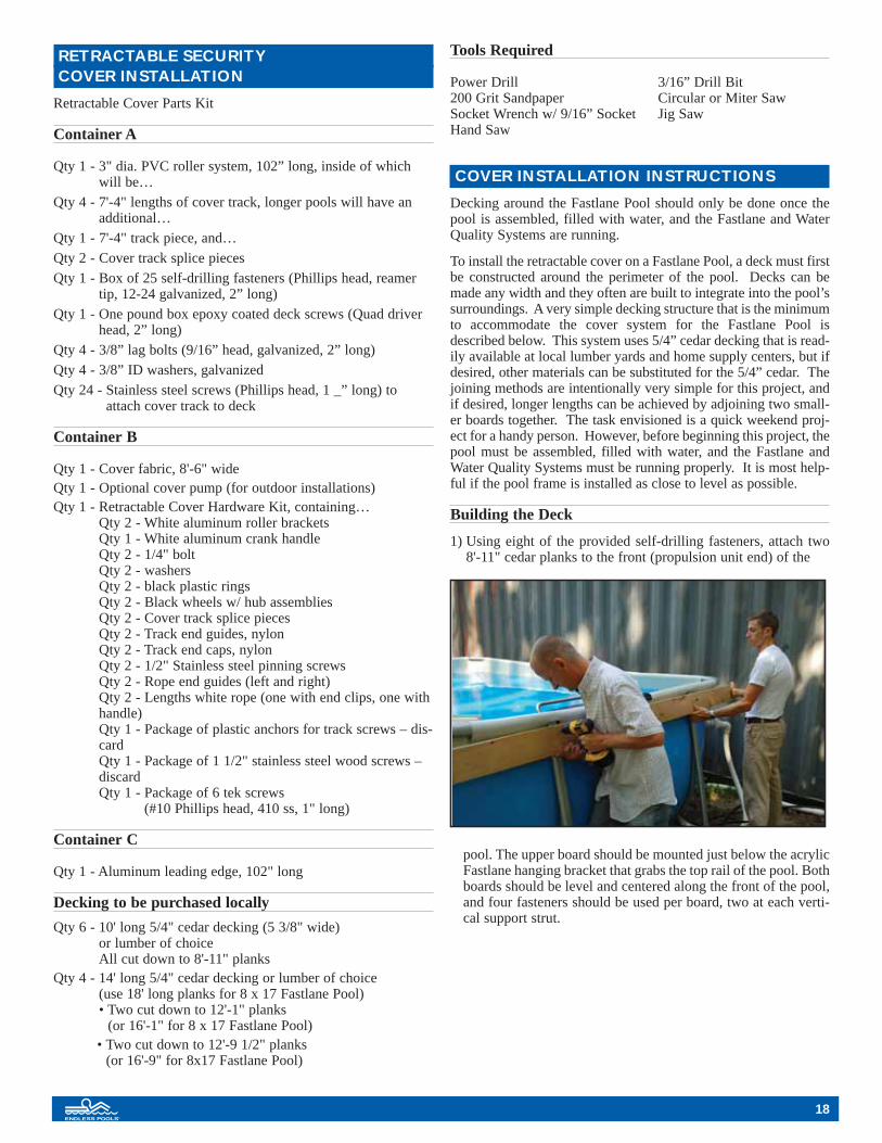
1) Using eight of the provided self-drilling fasteners, attach two8'-11" cedar planks to the front (propulsion unit end) of the
pool. The upper board should be mounted just below the acrylicFastlane hanging bracket that grabs the top rail of the pool. Bothboards should be level and centered along the front of the pool,and four fasteners should be used per board, two at each verti-cal support strut.

2) Using the provided 2" deck screws, attach the third 8'-11"cedar plank to the top of the two planks that are alreadyattached to the pool frame so that the top edge of this thirdplank is flush with the top of the pool.
3) Along the length of the pool on both sides, attach the 12'-9 1/2"cedar planks to the vertical struts using one self-drilling fas-
tener per strut. The fastener should be drilled through the plankand into the strut one inch from the bottom of the plank so that
the top edge of the plank should is flush with the top of thepool.
4) At the front of the pool, lay another 8'-11" plank flat against thetop edge of the vertical plank and the top of the pool’s frame,
19

making sure the ends of the top plank line up with the ends ofthe vertical plank. The top plank should overhang into the poolenough so that its back edge completely covers the vertical
plank’s top edge. Use the 2" deck screws to secure this hori-zontal top plank to the vertical plank on which it rests.
5) Along each side of the pool, attach a 12'-1" plank flat againstthe top edge of the vertical planks and the top of the pool’sframe. The ends of these planks should butt against the top 8'-11" plank at the front of the pool, and the edges of these planks
should line up with the ends of that 8'-11" plank as well. Use the2" deck screws to secure these horizontal top planks to the verti-cal planks on which they rest. Once installed, there will be anapproximate 3" overhang created by the top planks along the sidesof the pool over the vertical planks along the sides of the pool.
6) The final two 8'-11" planks of 5/4" cedar decking are used atthe rear of the pool. Place one piece flat against the struts sothat the top edge of the cedar is level with the top rail of therear of the pool. The ends of this plank should align with theedges of the top planks (that were just attached) along the sidesof the pool. Using two self-drilling fasteners (one fastener perstrut), attach this plank to the pool’s vertical struts.
20

7) In order to best accommodate the ladder, create a notch meas-uring 22 1/2" long and 2 1/2" deep in the center (or in a pre-ferred ladder location) of the final 8'-11" cedar plank. Do not
discard this piece that has been cut out, as it will be later usedto help attach the ladder to the pool deck.
8) Using the 2" deck screws, this plank should then be attached tothe vertical plank at the rear of the pool, so that its back edge
completely covers the vertical plank’s top edge, and it fits neat-ly between the edges of the two top planks along the sides ofthe pool.
9) Using the scrap cedar plank material from when the originalplanks were cut, place one end of the drop-off against the edgesof cedar planks at the front (right and left) corners of the pool.
Trace the horizontal top surface along the scrap piece, and cutthe piece so that the angle makes an attractive cover piece for
21

the front corners of the pool. Repeat for the other side, and usethe 2" deck screws to attach these pieces to the front corners ofthe pool.
10) Again, following the same concept that was discussed in theprevious step, use scrap material to create a vertical deckingsurface at the front (right and left) corners of the pool. This
short plank will be installed planar with the horizontal top cedarplank (installed in Step 2 of Building the Deck), and will betrimmed so that its bottom does not extend below the othercedar planks already installed at the front of the pool. Thesecorner areas must be planar with one another so that the cover
brackets and lag bolts (to be installed in a future step) will havea rigid surface to mount against and bite into, allowing thecover roller to function properly.
INSTALLING THE LADDER
When using a retractable cover with the Fastlane Pool, the ladder(assembled as per the instructions included in its box) must beplaced at the rear of the pool so that it does not interfere with theoperation of the cover. To allow the retractable cover’s fabric tooptimally cover the water’s surface area in the rear of the pool, itis best to notch the ladder as described below. This work shouldbe done before the ladder is positioned in the pool, and will requirea hand saw, sandpaper, and the same drill with Phillips head bitthat was used to assemble the deck.
1) Working only on the part of the ladder that will be inside thepool, a handsaw should be used to cut the lower parts of the lad-der’s hand rails free from the body of the ladder. The first cutshould be made at the hand rail’s lower support so that the
cut surface is flush against the main body of the ladder. A secondcut should be made immediately underneath the hand rail’s uppersupport that extends from the platform level of the ladder, and thecut surface should be flush against the underside of the upper sup-port piece, thus freeing the lower portion of the hand rail from theladder body. Be sure to perform these two cuts on both of the lad-der’s hand rails that will be inside the pool. Once the lower por-tions of the hand rails have been removed, the rough surfaceswhere all four of the cuts have been made can be sanded smooth.
22

23
2) Place the notch cutout piece (saved from Step 7 of Building theDeck) on the horizontal deck plank at the rear of the pool sothat the outside edge of the piece is flush with the outside edgeof the plank, and the middle of the piece is centered within theedges of the previously made cutout. Use two of the 2" deckscrews to attach the notch cutout piece to the rear plank, beingcareful that the tip of the screw does not touch the pool fabricand that it does not damage the top rail of the pool frame.
3) Lift the ladder assembly over the decking and into the pool sothat it now straddles the decking along the top rail at the rearof the pool. Position the ladder in the pool so that the back of
its legs fit into the notch that was cut earlier, and it is pushedtight against the top rail / plank at the rear of the pool. The twoholes in the ladder platform that are closest to the pool watershould now cover the notch cutout piece that was just attachedto the decking. Using two of the 2" deck screws, secure the lad-der to the notch cutout piece through these two holes
INSTALLING THE COVER
1) Lay the tracks on each side of the pool so that the opening inthe track is facing towards the water. The track should be flushwith the inside edge of the decking. For the standard lengthFastlane Pool, one length of 7'-4" track needs to be cut downto 5'-6" for each side of the pool. (For the longer 8 x 17Fastlane Pool, an additional 7'-4" piece has been included inthe shipment, and needs to be trimmed to two lengths of 2'-2".In this case, two 7'-4" lengths and a 2'-2" length of cover trackare used on each side of the pool.) When installed, the totaltrack length should be 12'-10" for a standard Fastlane Pool, and16'-10" for the longer Fastlane Pool. The inside distancebetween the two tracks should be approximately 8'. The fabricis 8'-6" wide and is designed to rest on the water surface.

24
2) Install the track splice between the adjoining tracks. Slide theplate into the extrusion end of both tracks before placing thesecond track on the deck. Two extra splice plates have beenincluded for the longer Fastlane Pool to help secure the extra2'-2" long cover track extrusions.
3) Insert black end guides into the end of the track near the rollerat the front of the pool. Refer to Figure 1 and use the provid-ed 1 1/4" stainless steel wood screws to secure the track to thewood. Note: Do not use the mounting hardware found in theRetractable Cover Parts Kit.
4) Slide the hub into the end of the 3" PVC pipe and attach thehub to the pipe using the self tapping screw that was providedwith the rocky roller kit. Slide the black plastic bushing overthe hub end.
5) Insert the hub end into the white roller bracket and place theblack plastic washer over the hub end.

25
6) Slide the handle over the hub and secure it to the hub using the5/16" bolt and washer.
7) Repeat the process for the other end of the pipe, but install thewhite knob instead of the handle.
8) Place the roller assembly onto the front of the pool so that the footof the roller bracket is aligned with the top edge of the verticalcedar plank. Using the oval slots in the foot of the roller bracket,mark the plank for pre-drilling the lag bolt holes into the wood.
9) Pre-drill the holes for the lag bolts using a 3/16" bit. On one side,start two of the provided lag bolts (with washers) into the pre-drilled holes. Slide the roller bracket onto these lag bolts, andthen tighten them to loosely anchor the roller bracket to the cedarplank.

26
10) Now repeat the process at the other end of the pool for theother anchor bracket. Drill the hole, and using the washer andlag bolt, loosely anchor that roller bracket to the plank. Oncecomfortable that the roller mechanism is level and that itfunctions properly, tighten all lag bolts to secure the bracketsand roller mechanism in place.
11) Unfold the cover fabric so that the Cover Pools label is facingup. There is a beaded edge on three sides of the fabric; twolong sides and an end. Slide the leading edge onto the endbead so that the eye hooks on the leading edge are angled up.Center the leading edge on the fabric and secure by threadinga 1/2" pan head screw into the bead through one of the pre-drilled holes in the leading edge at each end.
12) Remove the top half of the black end guide. Bring the leadingedge and fabric up to the track guide. Slide the long sidebeaded edge into the track opening and pull the fabric all the
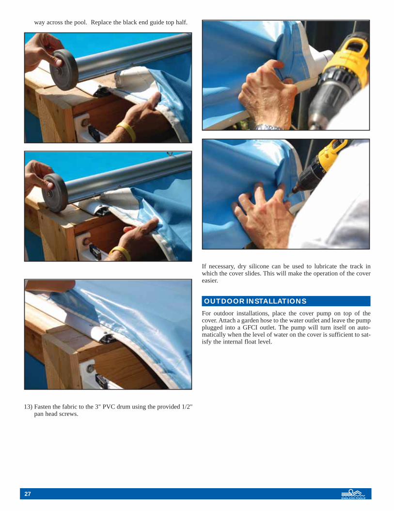
27
way across the pool. Replace the black end guide top half.
13) Fasten the fabric to the 3" PVC drum using the provided 1/2"pan head screws.
If necessary, dry silicone can be used to lubricate the track inwhich the cover slides. This will make the operation of the covereasier.
OUTDOOR INSTALLATIONS
For outdoor installations, place the cover pump on top of thecover. Attach a garden hose to the water outlet and leave the pumpplugged into a GFCI outlet. The pump will turn itself on auto-matically when the level of water on the cover is sufficient to sat-isfy the internal float level.

28

29

30
Wiring Schematic for 60hz Heater/Controller
GroundLine 2
NeutralLine 1
G/yR
WB
Ground
Line 2
Neutral
Line 1B
W
R
G/y
Wiring Schematic for 60hz Power Unit 230v, 24 amp, single phase
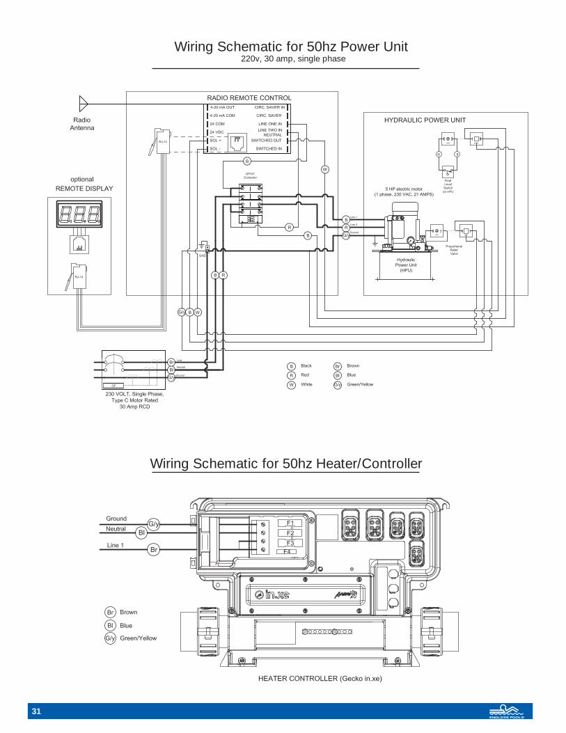
Wiring Schematic for 50hz Heater/Controller
Wiring Schematic for 50hz Power Unit 220v, 30 amp, single phase
31

32
FASTLANE POOL™ LIMITED WARRANTY
ENDLESS POOLS, INC. WARRANTS TO THE ORIGINAL PURCHASER OF THE FASTLANE POOL MANUFAC-TURED BY US TO BE FREE FROM DEFECTS IN MATERIALS AND WORKMANSHIP UNDER NORMAL USEFOR TWO YEARS FROM PURCHASE.
Our obligation under the warranty shall be limited to the repair or exchange (at our option) of any part or parts which maythus prove defective under normal use within two years from date of purchase by the original purchaser, and which ourexamination shall disclose to our satisfaction to be thus defective. All labor costs for removal and re-installation of thedefective part and all freight charges shall be paid by the purchaser and will not be reimbursed by Endless Pools, Inc. Thiswarranty is expressly in lieu of all other warranties expressed or implied including the warranties of merchantability andfitness for use and of all other obligations or liabilities for all damages direct or consequential to person, property or busi-ness whether or not occasioned by our negligence, and we neither assume for us any other liability in connection with thesale of this Fastlane Pool.
IN ADDITION, ENDLESS POOLS, INC. OFFERS A TEN-YEAR STRUCTURAL WARRANTY ON THE POOLLINER AND METAL STRUCTURE FRAME. If a component should deteriorate beyond structural use in this ten-yearperiod, we will repair or replace the component at our option after receipt and inspection of the defective part. The struc-tural warranty is voided when suitable drainage is not provided, and/or parts are not properly bonded, as stipulated in theinstallation instructions.
THIS WARRANTY SHALL NOT APPLY TO THIS FASTLANE POOL OR ANY PART THEREOF, WHICH HAS BEENSUBJECT TO ACCIDENT, NEGLIGENCE, FREEZING, IMPROPER INSTALLATION OR OPERATION, ALTER-ATION, ABUSE OR MISUSE. THIS INCLUDES, BUT IS NOT LIMITED TO, FLOW RESTRICTIONS OROBSTRUCTIONS ON ALL WATER AND HYDRAULIC SYSTEMS AND NOT PROPERLY BONDING OR MAIN-TAINING PROPER WATER CHEMISTRY (pH level must be maintained between 7.4 and 7.8 and total alkalinity between80 and 120 ppm. The total dissolved solids (TDS) must be no greater than 3,000 ppm). POOLS USING SALT CHLORINEGENERATORS MUST MAINTAIN A SALT CONTENT BELOW 4,000 ppm AND TDS WITH SALT BELOW 7,000ppm. Your warranty does not cover problems arising in whole or part from:
• Set-up of pool more than 3”out of level or having the pool up without being full of water. • Acts of God, abnormal weather conditions, circumstances beyond the control of Endless Pools, Inc. or
damage from plants or animals. • Bad odors emanating from the pool liner, puncture, abrasion, or cutting.• Aesthetic tears or rips caused by any type of undue stress during assembly/disassembly.• Aesthetic blemishes or tears not compromising structure or pools ability to hold water.• Accident and injury or damages from diving, sliding or jumping into the pool.• A product used for commercial or institutional purposes.
The term “original purchaser”, as used in this warranty, shall be deemed to mean the person for whom the Fastlane Poolwas originally installed. This warranty shall apply only within the boundaries of the continental United States.
We DO NOT warrant this machine to meet requirements of any safety code of any state, municipality, or other jurisdic-tion. Purchaser assumes all risk and liability whatsoever resulting from the use thereof.
In order to claim this warrant, original purchaser must promptly notify our Customer Service Department in writing of theexistence of the claim and then follow our written instructions regarding the procedures for remedying the defect. EndlessPools, Inc. shall not be responsible for cartage, transportation, removal and/or reinstallation labor or any other such costsrelating to performance of the warranty. In the event any portion of this warranty shall be deemed unenforceable by a courtof law, the remainder of this warranty shall remain in full force and effect as if the voided portion were never included.
Prepaid returns of all Endless Pool products are accepted less a 10% restocking fee, up to 30 days from the date of purchase if undamaged and in its original shipping containers. Accessories, options and equipment that have been used are non-refundable. Before returning any product, you must call our Customer Service Department to receive proper return authorization.
Endless Pools, Inc., 1601 Dutton Mill Rd., Aston, PA 19014 800-910-2714
.

Endless Pools, Inc. • 1601 Dutton Mill Rd • Aston, PA 19014-2931800-910-2714 • 610-497-8693 fax • www.myendlesspool.com OM28 10-09


