Installation Bard
26
Page 1 of 26 INSTALLATION INSTRUCTIONS WALL MOUNTED PACKAGE AIR CONDITIONERS MODELS W17A2 W17L2 W18A2 W18L2 W24A2 W24L2 W30A2 W30L2 W36A2 W36L2 W42A2 W42L2 W48A2 W48L2 W60A2 W60L2 W70A2 W70L2 Manual : 2100-581A Supersedes: 2100-581 File: Volume III Tab 16 Date: 03-04-13 Bard Manufacturing Company, Inc. Bryan, Ohio 43506 Since 1914...Moving ahead just as planned.
-
Upload
mukti-awan -
Category
Documents
-
view
283 -
download
0
description
Air Conditioning
Transcript of Installation Bard
Manual 2100-581A Page 1 of 26
INSTALLATION INSTRUCTIONS
WALL MOUNTED PACKAGE AIR CONDITIONERS
MODELS W17A2 W17L2 W18A2 W18L2 W24A2 W24L2 W30A2 W30L2 W36A2 W36L2 W42A2 W42L2 W48A2 W48L2 W60A2 W60L2 W70A2 W70L2
Manual : 2100-581ASupersedes: 2100-581File: Volume III Tab 16Date: 03-04-13
Bard Manufacturing Company, Inc.Bryan, Ohio 43506
Since 1914...Moving ahead just as planned.
Manual 2100-581A Page 2 of 26
Contents
FiguresFigure 1 Fresh Air Damper Assembly ..................... 5Figure 2 Unit Dimensions ....................................... 7Figure 3A Mounting Instructions ............................... 8Figure 3B Mounting Instructions - W17 – 36 ................9Figure 3C Mounting Instructions - W42, 48, 60, 70 ....10Figure 4 Electric Heat Clearance ......................... 11Figure 5 Wall Mounting Instructions ..................... 12Figure 6 Wall Mounting Instructions ..................... 12Figure 7 Common Wall Mounting Installations ..... 13Figure 8 Fan Blade Setting ................................... 18
TablesTable 1 Fan Blade Dimensions ........................... 18Table 2 Cooling Pressure .................................... 19Table 3 Electrical Specifications W**A ................ 20Table 4 Electrical Specifications W**L ................ 21Table 5 Recommended Airflow ........................... 22Table 6 Indoor Blower Performance ................... 22Table 7 Maximum ESP Electric Heat Only .......... 22Table 8 Electric Heat ........................................... 23Table 9A Optional Accessories — Right Hand ...... 24Table 9B Optional Accessories — Left Hand ............25Table 10 Vent & Control Options ........................... 26
Getting Other Information and Publications 3
Wall Mount General InformationWall Mount Model Nomenclature .............................. 4Shipping Damage ..................................................... 4General ................................................................. 4Duct Work ................................................................. 5Filters ................................................................. 5Fresh Air Intake ......................................................... 5Condensate Drain .................................................... 5
Installation Instructions Wall Mounting Information ........................................ 6Mounting the Unit ...................................................... 6Clearances Required ................................................ 6Minimum Clearances ................................................ 6Wiring – Main Power ............................................... 14Wiring – Low Voltage Wiring ................................... 14
Start UpGeneral ............................................................... 15Topping Off System Charge .................................... 15Safety Practices ...................................................... 15Important Installer Note ........................................... 16High Pressure Switch .............................................. 16Three Phase Scroll Compressor ............................. 16Phase Monitor ......................................................... 16Condenser Fan Operation ...................................... 16Service Hints ........................................................... 16Sequence of Operation ........................................... 17Compressor Control Module ................................... 17Adjustments ............................................................ 17Pressure Service Ports ........................................... 17
TroubleshootingFan Blade Setting Dimensions ................................ 18R-410A Refrigerant Charge .................................... 18Removal of Fan Shroud .......................................... 18
Manual 2100-581A Page 3 of 26
GETTING OTHER INFORMATION AND PUBLICATIONS
These publications can help you install the air conditioner or heat pump. You can usually find these at your local library or purchase them directly from the publisher. Be sure to consult current edition of each standard.
National Electrical Code .......................ANSI/NFPA 70
Standard for the Installation ............... ANSI/NFPA 90A of Air Conditioning and Ventilating Systems
Standard for Warm Air ....................... ANSI/NFPA 90B Heating and Air Conditioning Systems
Load Calculation for ......................... ACCA Manual J Residential Winter and Summer Air Conditioning
Duct Design for Residential ............... ACCA Manual D Winter and Summer Air Conditioning and Equipment Selection
FOR MORE INFORMATION, CONTACT THESE PUBLISHERS:
ACCA Air Conditioning Contractors of America 1712 New Hampshire Ave. N.W. Washington, DC 20009 Telephone: (202) 483-9370 Fax: (202) 234-4721
ANSI American National Standards Institute 11 West Street, 13th Floor New York, NY 10036 Telephone: (212) 642-4900 Fax: (212) 302-1286
ASHRAE American Society of Heating, Refrigeration and Air Conditioning Engineers, Inc. 1791 Tullie Circle, N.E. Atlanta, GA 30329-2305 Telephone: (404) 636-8400 Fax: (404) 321-5478
NFPA National Fire Protection Association Batterymarch Park P.O. Box 9101 Quincy, MA 02269-9901 Telephone: (800) 344-3555 Fax: (617) 984-7057
Manual 2100-581A Page 4 of 26
WALL MOUNT GENERAL INFORMATION
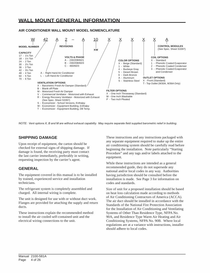
AIR CONDITIONER WALL MOUNT MODEL NOMENCLATURE
W 42 A 2 – A 10 X X X X X A
NOTE: Vent options X, B and M are without exhaust capability. May require separate field supplied barometric relief in building.
SHIPPING DAMAGEUpon receipt of equipment, the carton should be checked for external signs of shipping damage. If damage is found, the receiving party must contact the last carrier immediately, preferably in writing, requesting inspection by the carrier’s agent.
GENERALThe equipment covered in this manual is to be installed by trained, experienced service and installation technicians.
The refrigerant system is completely assembled and charged. All internal wiring is complete.
The unit is designed for use with or without duct work. Flanges are provided for attaching the supply and return ducts.
These instructions explain the recommended method to install the air cooled self-contained unit and the electrical wiring connections to the unit.
These instructions and any instructions packaged with any separate equipment required to make up the entire air conditioning system should be carefully read before beginning the installation. Note particularly “Starting Procedure” and any tags and/or labels attached to the equipment.
While these instructions are intended as a general recommended guide, they do not supersede any national and/or local codes in any way. Authorities having jurisdiction should be consulted before the installation is made. See Page 3 for information on codes and standards.
Size of unit for a proposed installation should be based on heat loss calculation made according to methods of Air Conditioning Contractors of America (ACCA). The air duct should be installed in accordance with the Standards of the National Fire Protection Association for the Installation of Air Conditioning and Ventilating Systems of Other Than Residence Type, NFPA No. 90A, and Residence Type Warm Air Heating and Air Conditioning Systems, NFPA No. 90B. Where local regulations are at a variance with instructions, installer should adhere to local codes.
KWMODEL NUMBER CONTROL MODULES
(See Spec. Sheet S3397)
VOLTS & PHASEA - 230/208/60/1B - 230/208/60/3C - 460/60/3
REVISIONS
VENTILATION OPTIONSX - Barometric Fresh Air Damper (Standard)B - Blank-off PlateM - Motorized Fresh Air DamperV - Commercial Ventilator - Motorized with ExhaustR - Energy Recovery Ventilator - Motorized with Exhaust (See Spec. Sheet S3397)S - Economizer - School Versions, EnthalpyW - Economizer - Equipment Building, EnthalpyT - Economizer - Equipment Building, DB Temp.
FILTER OPTIONSX - One Inch Throwaway (Standard)W - One Inch WashableP - Two Inch Pleated
COLOR OPTIONSX - Beige (Standard)1 - White4 - Buckeye Gray5 - Desert Brown6 - Dark BronzeA - AluminumS - Stainless Steel
COIL OPTIONSX - Standard1 - Phenolic Coated Evaporator2 - Phenolic Coated Condenser3 - Phenolic Coated Evaporator and Condenser
OUTLET OPTIONSX - Front (Standard)T - Top Outlet (W30A, W36A Only)
CAPACITY17 - 1½ Ton18 - 1½ Ton24 - 2 Ton30 - 2½ Ton36 - 3 Ton42 - 3½ Ton48 - 4 Ton60 - 5 Ton70 - 6 Ton
A - Right Hand Air ConditionerL - Left Hand Air Conditioner
Manual 2100-581A Page 5 of 26
DUCT WORKAll duct work, supply and return, must be properly sized for the design airflow requirement of the equipment. Air Conditioning Contractors of America (ACCA) is an excellent guide to proper sizing. All duct work or portions thereof not in the conditioned space should be properly insulated in order to both conserve energy and prevent condensation or moisture damage.
Refer to Maximum ESP of operation Electric Heat Table 7.
Design the duct work according to methods given by the Air Conditioning Contractors of America (ACCA). When duct runs through unheated spaces, it should be insulated with a minimum of one inch of insulation. Use insulation with a vapor barrier on the outside of the insulation. Flexible joints should be used to connect the duct work to the equipment in order to keep the noise transmission to a minimum.
Models W17 - W24 as approved for zero inch clearance to the supply duct. For model series W30, W36, W42, W48, W60 and W70 a 1/4 inch clearance to combustible material for the first three feet of duct attached to the outlet air frame is required. See Wall Mounting Instructions and Figures 3 and 4 for further details.
Ducts through the walls must be insulated and all joints taped or sealed to prevent air or moisture entering the wall cavity.
Some installations may not require any return air duct. A metallic return air grille is required with installations not requiring a return air duct. The spacing between louvers on the grille shall not be larger than 5/8 inch.
Any grille that meets with 5/8 inch louver criteria may be used. It is recommended that Bard Return Air Grille Kit RG2 through RG5 or RFG2 through RFG5 be installed when no return duct is used. Contact distributor or factory for ordering information. If using a return air filter grille, filters must be of sufficient size to allow a maximum velocity of 400 fpm.
NOTE: If no return air duct is used, applicable installation codes may limit this cabinet to installation only in a single story structure.
FILTERSA 1-inch throwaway filter is standard with each unit. The filter slides into position making it easy to service. This filter can be serviced from the outside by removing the filter access panel. A 1-inch washable filter and 2-inch pleated filter are also available as optional accessories. The internal filter brackets are adjustable to accommodate the 2-inch filter by bending two (2) tabs down on each side of the filter support bracket.
FRESH AIR INTAKEAll units are built with fresh air inlet slots punched in the service door.
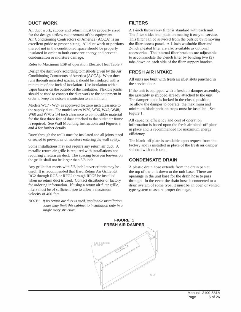
If the unit is equipped with a fresh air damper assembly, the assembly is shipped already attached to the unit. The damper blade is locked in the closed position. To allow the damper to operate, the maximum and minimum blade position stops must be installed. See Figure 1.
All capacity, efficiency and cost of operation information is based upon the fresh air blank-off plate in place and is recommended for maximum energy efficiency.
The blank-off plate is available upon request from the factory and is installed in place of the fresh air damper shipped with each unit.
CONDENSATE DRAIN A plastic drain hose extends from the drain pan at the top of the unit down to the unit base. There are openings in the unit base for the drain hose to pass through. In the event the drain hose is connected to a drain system of some type, it must be an open or vented type system to assure proper drainage.
FIGURE 1FRESH AIR DAMPER
Manual 2100-581A Page 6 of 26
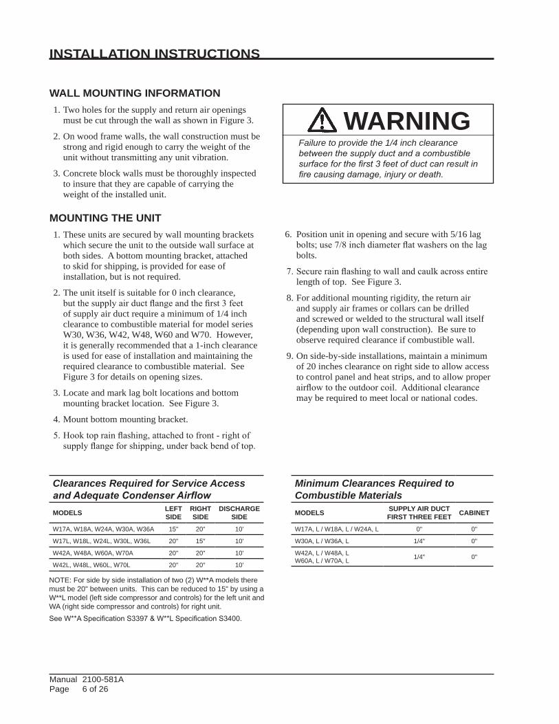
Clearances Required for Service Access and Adequate Condenser AirflowMODELS LEFT
SIDERIGHTSIDE
DISCHARGE SIDE
W17A, W18A, W24A, W30A, W36A 15" 20" 10'
W17L, W18L, W24L, W30L, W36L 20" 15" 10'
W42A, W48A, W60A, W70A 20" 20" 10'
W42L, W48L, W60L, W70L 20" 20" 10'
Minimum Clearances Required toCombustible MaterialsMODELS SUPPLY AIR DUCT
FIRST THREE FEET CABINET
W17A, L / W18A, L / W24A, L 0" 0"
W30A, L / W36A, L 1/4" 0"
W42A, L / W48A, L W60A, L / W70A, L 1/4" 0"
NOTE: For side by side installation of two (2) W**A models there must be 20" between units. This can be reduced to 15" by using a W**L model (left side compressor and controls) for the left unit and WA (right side compressor and controls) for right unit.See W**A Specification S3397 & W**L Specification S3400.
INSTALLATION INSTRUCTIONS
WARNINGFailure to provide the 1/4 inch clearance between the supply duct and a combustible surface for the first 3 feet of duct can result in fire causing damage, injury or death.
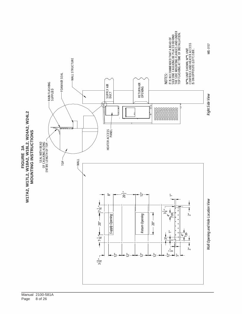
WALL MOUNTING INFORMATION 1. Two holes for the supply and return air openings
must be cut through the wall as shown in Figure 3.
2. On wood frame walls, the wall construction must be strong and rigid enough to carry the weight of the unit without transmitting any unit vibration.
3. Concrete block walls must be thoroughly inspected to insure that they are capable of carrying the weight of the installed unit.
MOUNTING THE UNIT 1. These units are secured by wall mounting brackets
which secure the unit to the outside wall surface at both sides. A bottom mounting bracket, attached to skid for shipping, is provided for ease of installation, but is not required.
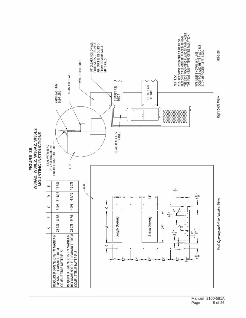
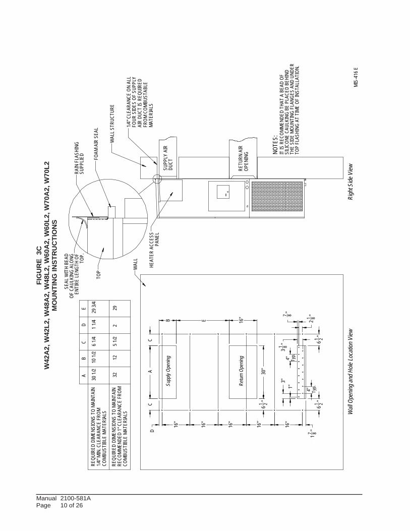
2. The unit itself is suitable for 0 inch clearance, but the supply air duct flange and the first 3 feet of supply air duct require a minimum of 1/4 inch clearance to combustible material for model series W30, W36, W42, W48, W60 and W70. However, it is generally recommended that a 1-inch clearance is used for ease of installation and maintaining the required clearance to combustible material. See Figure 3 for details on opening sizes.
3. Locate and mark lag bolt locations and bottom mounting bracket location. See Figure 3.
4. Mount bottom mounting bracket.
5. Hook top rain flashing, attached to front - right of supply flange for shipping, under back bend of top.
6. Position unit in opening and secure with 5/16 lag bolts; use 7/8 inch diameter flat washers on the lag bolts.
7. Secure rain flashing to wall and caulk across entire length of top. See Figure 3.
8. For additional mounting rigidity, the return air and supply air frames or collars can be drilled and screwed or welded to the structural wall itself (depending upon wall construction). Be sure to observe required clearance if combustible wall.
9. On side-by-side installations, maintain a minimum of 20 inches clearance on right side to allow access to control panel and heat strips, and to allow proper airflow to the outdoor coil. Additional clearance may be required to meet local or national codes.
Manual 2100-581A Page 7 of 26
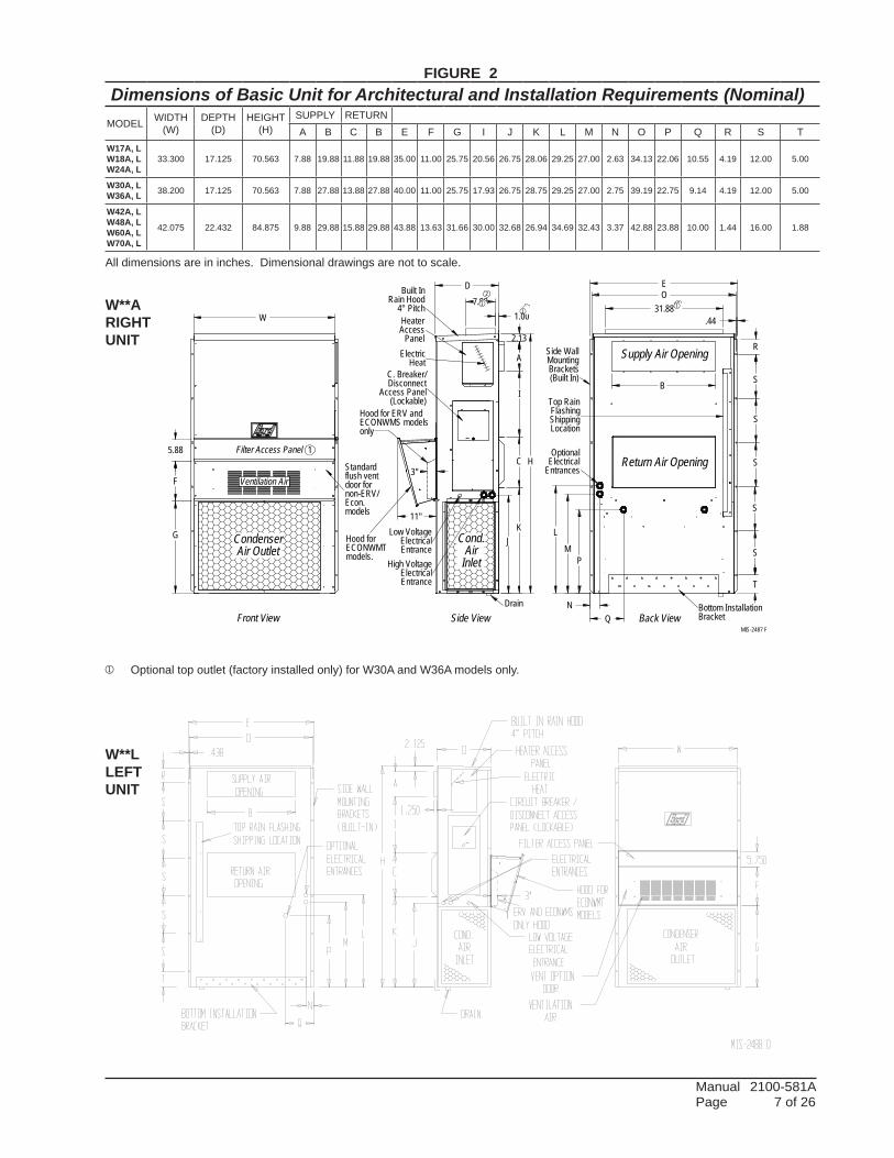
Dimensions of Basic Unit for Architectural and Installation Requirements (Nominal)MODEL WIDTH
(W)DEPTH
(D)HEIGHT
(H)SUPPLY RETURNA B C B E F G I J K L M N O P Q R S T
W17A, LW18A, LW24A, L
33.300 17.125 70.563 7.88 19.88 11.88 19.88 35.00 11.00 25.75 20.56 26.75 28.06 29.25 27.00 2.63 34.13 22.06 10.55 4.19 12.00 5.00
W30A, LW36A, L 38.200 17.125 70.563 7.88 27.88 13.88 27.88 40.00 11.00 25.75 17.93 26.75 28.75 29.25 27.00 2.75 39.19 22.75 9.14 4.19 12.00 5.00
W42A, LW48A, LW60A, LW70A, L
42.075 22.432 84.875 9.88 29.88 15.88 29.88 43.88 13.63 31.66 30.00 32.68 26.94 34.69 32.43 3.37 42.88 23.88 10.00 1.44 16.00 1.88
31.88
3"
7.881.00
11"
Filter Access Panel
Air Outlet
Front View
Condenser
Standardflush ventdoor fornon-ERV/Econ.models
Ventilation Air
W
5.88
F
G
ElectricalEntrances
Optional
Side WallMounting Supply Air Opening
(Built In)
ShippingLocation
Brackets
Return Air Opening
Top RainFlashing
Bottom InstallationBracketBack View
B
PM
OE
R
S
S
S
S
S
T
.44
NQ
L
DisconnectAccess Panel
Low Voltage
Entrance
Entrance
Electrical
Side View
High Voltage
Cond.
Electrical
Drain
InletAir
Heater
PanelAccess
Rain HoodBuilt In
4° Pitch
(Lockable)
C. Breaker/
Hood for ERV andECONWMS modelsonly
2.13
A
I
D
J
C H
K
1
2
Heat
models.
MIS-2487 F
22
Electric
Hood forECONWMT
j Optional top outlet (factory installed only) for W30A and W36A models only.
FIGURE 2
All dimensions are in inches. Dimensional drawings are not to scale.
W**ARIGHTUNIT
W**LLEFTUNIT
jj
j
Manual 2100-581A Page 8 of 26
FIG
UR
E 3
AW
17A
2, W
17L2
, W18
A2,
W18
L2, W
24A
2, W
24L2
MO
UN
TIN
G IN
STR
UC
TIO
NS
12"
12"
12"
12"
12"
20"
20"
1"3"
4" Typ.
8" 201 2"
12"
1"
31 8"4" Ty
p.
5"
7 8"
313 16"
2"2"
71 16
"1 16
"7
CONT
ROLS
AND
HEAT
ERAC
CESS
NOTE
S:
TOP
TOP
FLAS
HING
AT T
IME
OF IN
STAL
LATI
ON.
OPEN
ING
MIS-
3157
ENTI
RE LE
NGTH
OF T
OP.
RETU
RNAI
R
DUCT
Wall
Open
ingan
dHole
Loca
tionV
iewRi
ghtS
ideVi
ew
OFCA
ULKI
NGAL
ONG
PANE
L
FOAM
AIR
SEAL
WAL
LSTR
UCTU
RE
WAL
L
HEAT
ERAC
CESS
RAIN
FLA
SHIN
G SILIC
ONE
CAUL
KING
BEPL
ACED
BEHI
ND
ISON
OPPO
SITE
(LEF
T)SI
DE.
THE
SIDE
MOUN
TING
FLA
NGES
AND
UNDE
R
SEAL
WIT
HBE
AD
IT IS
RECO
MMEN
DED
THAT
ABE
ADOF
W**A
UNIT
SHOW
N,W
**LUN
IT
SUPP
LYAI
R
SUPP
LIED
Retur
n Ope
ning
Supp
ly Op
ening
Manual 2100-581A Page 9 of 26
FIG
UR
E 3
BW
30A
2, W
30L2
, W36
A2,
W36
L2M
OU
NTI
NG
INST
RU
CTI
ON
S
28"
A
C
D
C
12"
12"
12"
12"
12"
51 16
"
B
E
14"
411 16
" 4
11 16"
4" Typ.
27 8"
7 8"7 8"
4" Typ.
7 8"
31 8"
W*R
UNIT
SHOW
N,W
*LUN
IT
MIS-
3158
ENTI
RE LE
NGTH
OF T
OP.
SUPP
LIED
SUPP
LYAI
R
TOP
OFCA
ULKI
NGAL
ONG
PANE
L
FOAM
AIR
SEAL
WAL
LSTR
UCTU
RE
RAIN
FLA
SHIN
G
FOUR
SIDE
SOF
SUPP
LYAI
RDU
CT IS
REQU
IRED
FROM
COMB
USTA
BLE
MATE
RIAL
S
NOTE
S:
1/4"C
LEAR
ANCE
ONAL
L
HEAT
ERAC
CESS
TOP
FLAS
HING
AT T
IME
OF IN
STAL
LATI
ON.
THE
SIDE
MOUN
TING
FLA
NGES
AND
UNDE
RSI
LICON
ECA
ULKI
NGBE
PLAC
EDBE
HIND
ISON
OPPO
SITE
(LEF
T)SI
DE.
OPEN
ING
CONT
ROLS
AND
HEAT
ERAC
CESS
DUCT
RETU
RNAI
R
Righ
tSide
View
SEAL
WIT
HBE
AD
IT IS
RECO
MMEN
DED
THAT
ABE
ADOF
WAL
L
Wall
Open
ingan
dHole
Loca
tionV
iew
Retur
n Ope
ning
167/8
47/16
45/8
97/8
297/8
175/8
311/1
653
/883
/828
3/8
ED
CB
A
COMB
USTI
BLE
MATE
RIAL
SRE
COMM
ENDE
D1"
CLEA
RANC
EFR
OMRE
QUIR
EDDI
MENS
IONS
TOMA
INTA
IN
COMB
USTI
BLE
MATE
RIAL
S1/4
"MIN
.CLE
ARAN
CEFR
OMRE
QUIR
EDDI
MENS
IONS
TOMA
INTA
IN Supp
ly Op
ening
Manual 2100-581A Page 10 of 26
FIG
UR
E 3
CW
42A
2, W
42L2
, W48
A2,
W48
L2, W
60A
2, W
60L2
, W70
A2,
W70
L2M
OU
NTI
NG
INST
RU
CTI
ON
S
D
16"
16"
16"
16"
16"
17 8"61 2"
61 2"21 8"7 8"
1"3"
4" Typ.
4" Typ.
61 2"30
"
E 16"
AC
C
31 8"
B
Wall
Open
ingan
dHole
Loca
tionV
iew
RETU
RN A
IR
1
REQU
IRED
DIM
ENSI
ONS
TOM
AINT
AIN
1/4"
MIN
.CLE
ARAN
CEFR
OMCO
MBU
STIB
LEM
ATER
IALS
REQU
IRED
DIM
ENSI
ONS
TOM
AINT
AIN
29
DUCT
COM
BUST
IBLE
MAT
ERIA
LS
AB
CD
E
301/
210
1/2
61/
41
1/4
293/
4
3212
51/
22
NOTE
S:WAL
L ST
RUCT
URE
1
SUPP
LY A
IR
IT IS
REC
OMM
ENDE
DTH
AT A
BEA
D OF
OPEN
ING
Righ
tSide
ViewRA
INFL
ASHI
NG
SILI
CONE
CAUL
KING
BE
PLAC
ED B
EHIN
D
RECO
MM
ENDE
D1"
CLEA
RANC
EFR
OM
THE
SIDE
MOU
NTIN
GFL
ANGE
S AN
DUN
DER
TOP
FLAS
HING
AT
TIM
E OF
INST
ALLA
TION
.
TOP.
PANE
LHE
ATER
ACC
ESS
FOUR
SID
ES O
F SU
PPLY
AIR
DUCT
IS R
EQUI
RED
FROM
COM
BUST
ABLE
WAL
L1/
4"CL
EARA
NCE
ON A
LL
MAT
ERIA
LS
Supp
ly Op
ening
FOAM
AIR
SEA
L
SUPP
LIED
SEAL
WIT
H BE
ADOF
CAUL
KING
ALO
NGEN
TIRE
LEN
GTH
OF
TOP
1
Retur
n Ope
ning
MIS
-416
E
Dim
ensio
nis
21"o
n95
" tall
units
.
2
Dim
ensio
nis
10"o
nT4
8H1
& T6
0H1.
2
Dim
ensio
nis
6"on
T48H
1 &
T60H
1.3
3
Manual 2100-581A Page 11 of 26
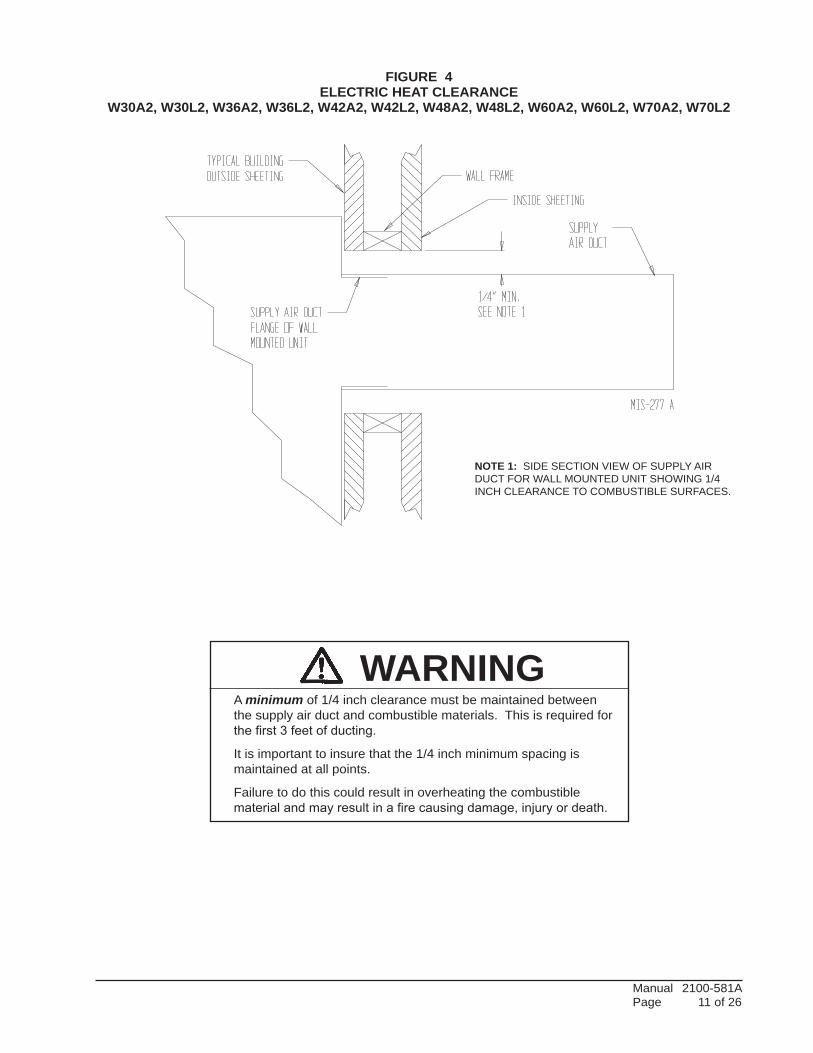
FIGURE 4ELECTRIC HEAT CLEARANCE
W30A2, W30L2, W36A2, W36L2, W42A2, W42L2, W48A2, W48L2, W60A2, W60L2, W70A2, W70L2
WARNINGA minimum of 1/4 inch clearance must be maintained between the supply air duct and combustible materials. This is required for the first 3 feet of ducting.
It is important to insure that the 1/4 inch minimum spacing is maintained at all points.
Failure to do this could result in overheating the combustible material and may result in a fire causing damage, injury or death.
NOTE 1: SIDE SECTION VIEW OF SUPPLY AIR DUCT FOR WALL MOUNTED UNIT SHOWING 1/4 INCH CLEARANCE TO COMBUSTIBLE SURFACES.
Manual 2100-581A Page 12 of 26
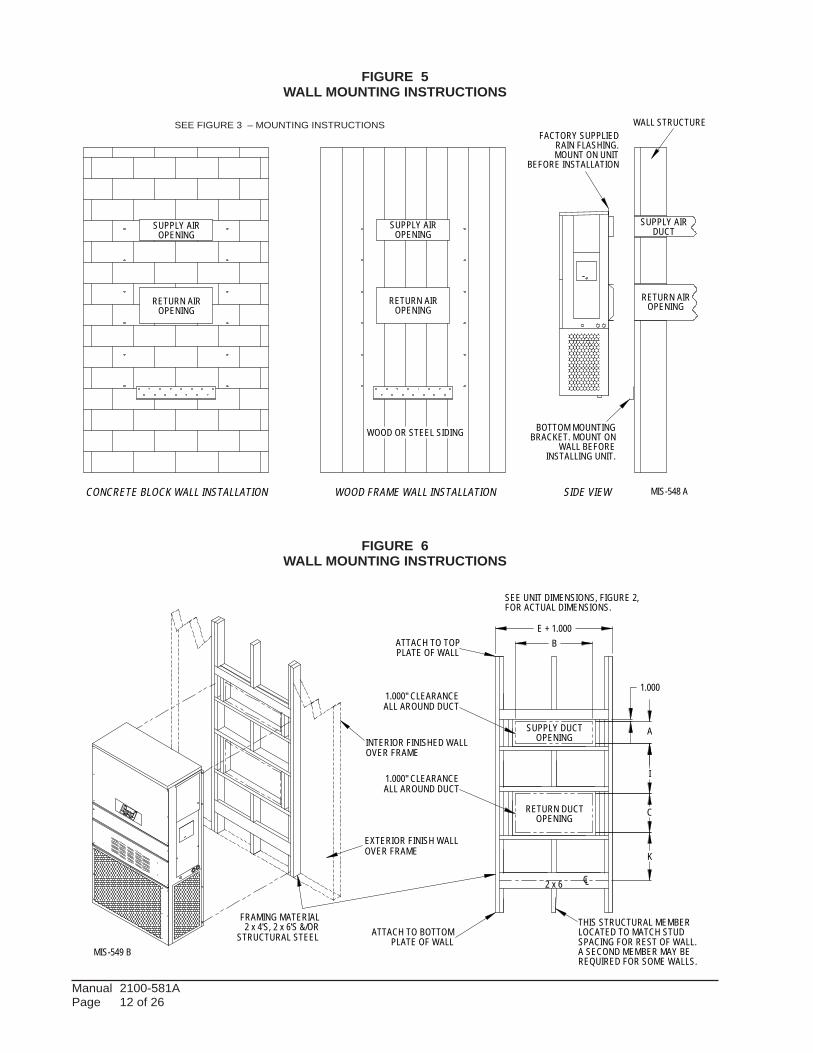
FIGURE 5WALL MOUNTING INSTRUCTIONS
FIGURE 6WALL MOUNTING INSTRUCTIONS
DUCT
OPENINGRETURN AIR
SUPPLY AIR
WOOD FRAME WALL INSTALLATION
OPENING
WALL BEFORE
MOUNT ON UNIT
OPENING
BEFORE INSTALLATION
BOTTOM MOUNTING
CONCRETE BLOCK WALL INSTALLATION
BRACKET. MOUNT ON
OPENING
WOOD OR STEEL SIDING
OPENING
INSTALLING UNIT.
RETURN AIR
WALL STRUCTURE
RETURN AIR
SUPPLY AIR
FACTORY SUPPLIEDRAIN FLASHING.
SUPPLY AIR
MIS-548 ASIDE VIEW
I
A
C
K
E + 1.000B
1.000
SUPPLY DUCT
OVER FRAME
INTERIOR FINISHED WALL
ALL AROUND DUCT
FRAMING MATERIAL
EXTERIOR FINISH WALL
OPENING
FOR ACTUAL DIMENSIONS.
2 x 4'S, 2 x 6'S &/ORSTRUCTURAL STEEL
ATTACH TO TOP
1.000" CLEARANCE
1.000" CLEARANCE
PLATE OF WALL
C
SEE UNIT DIMENSIONS, FIGURE 2,
OPENING
RETURN DUCT
2 x 6
ATTACH TO BOTTOM
OVER FRAME
PLATE OF WALL
L
THIS STRUCTURAL MEMBERLOCATED TO MATCH STUDSPACING FOR REST OF WALL.A SECOND MEMBER MAY BEREQUIRED FOR SOME WALLS.
MIS-549 B
ALL AROUND DUCT
SEE FIGURE 3 – MOUNTING INSTRUCTIONS
Manual 2100-581A Page 13 of 26
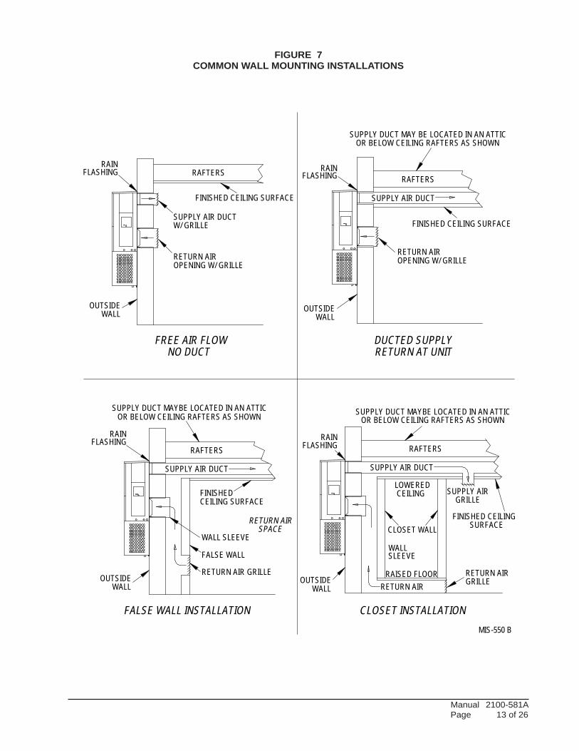
FIGURE 7COMMON WALL MOUNTING INSTALLATIONS
LOWERED
RAISED FLOOR
RAFTERS
SUPPLY AIRCEILING SURFACE
WALL SLEEVE
RETURN AIRCLOSET WALL
GRILLE
FLASHING
RETURN AIR
FLASHING
SUPPLY DUCT MAYBE LOCATED IN AN ATTICOR BELOW CEILING RAFTERS AS SHOWN
SUPPLY DUCT MAY BE LOCATED IN AN ATTIC
SURFACE
RAFTERS
FINISHED CEILING
SUPPLY AIR DUCT
WALL
OPENING W/ GRILLE
SUPPLY DUCT MAYBE LOCATED IN AN ATTICOR BELOW CEILING RAFTERS AS SHOWN
CEILING
RAIN
RETURN AIR
SLEEVEWALL
SUPPLY AIR DUCT
RAFTERSRAFTERS
RETURN AIROPENING W/ GRILLE
RAIN
FALSE WALL INSTALLATION
DUCTED SUPPLY
GRILLEOUTSIDE
SPACE
FALSE WALL
RETURN AIR GRILLEOUTSIDE
OR BELOW CEILING RAFTERS AS SHOWN
FINISHED CEILING SURFACE
RAINFLASHING
RAINFLASHING
RETURN AT UNITNO DUCT
WALL
SUPPLY AIR DUCT
CLOSET INSTALLATION
RETURN AIR
FINISHED
FINISHED CEILING SURFACE
MIS-550 B
FREE AIR FLOW
OUTSIDEWALL
OUTSIDEWALL
SUPPLY AIR DUCTW/ GRILLE
Manual 2100-581A Page 14 of 26
WIRING – MAIN POWERRefer to the unit rating plate for wire sizing information and maximum fuse or “HACR” type circuit breaker size. Each outdoor unit is marked with a “Minimum Circuit Ampacity”. This means that the field wiring used must be sized to carry that amount of current. Depending on the installed KW of electric heat, there may be two field power circuits required. If this is the case, the unit serial plate will so indicate. All models are suitable only for connection with copper wire. Each unit and/or wiring diagram will be marked “Use Copper Conductors Only”. These instructions must be adhered to. Refer to the National Electrical Code (NEC) for complete current carrying capacity data on the various insulation grades of wiring material. All wiring must conform to NEC and all local codes.
The electrical data lists fuse and wire sizes (75° C copper) for all models including the most commonly used heater sizes. Also shown are the number of field power circuits required for the various models with heaters.
The unit rating plate lists a “Maximum Time Delay Relay Fuse” or “HACR” type circuit breaker that is to be used with the equipment. The correct size must be used for proper circuit protection and also to assure that there will be no nuisance tripping due to the momentary high starting current of the compressor motor.
The disconnect access door on this unit may be locked to prevent unauthorized access to the disconnect. To convert for the locking capability, bend the tab located in the bottom left-hand corner of the disconnect opening under the disconnect access panel straight out. This tab will now line up with the slot in the door. When shut, a padlock may be placed through the hole in the tab preventing entry.
See “Start Up” section for important information on three phase scroll compressor start ups.
See Tables 3 & 4 for Electrical Specifications.
WIRING – LOW VOLTAGE WIRING All 230/208V, 1 phase and 3 phase equipment have dual primary voltage transformers. All equipment leaves the factory wired on 240V tap. For 208V operation, reconnect from 240V to 208V tap. The acceptable operating voltage range for the 240 and 208V taps are:
TAP RANGE 240 253 – 216 208 220 – 187
NOTE: Thevoltageshouldbemeasuredatthefieldpower connection point in the unit and while the unit is operating at full load (maximum amperage operating condition).
For wiring size and connections, refer to Wiring Manual 2100-507.
Manual 2100-581A Page 15 of 26
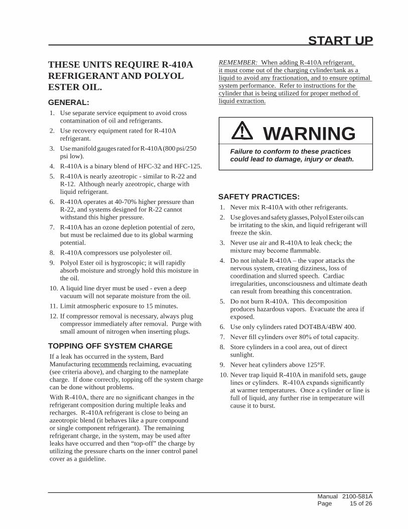
START UP
THESE UNITS REQUIRE R-410A REFRIGERANT AND POLYOL ESTER OIL.GENERAL:1. Use separate service equipment to avoid cross contamination of oil and refrigerants.2. Use recovery equipment rated for R-410A refrigerant.3. Use manifold gauges rated for R-410A (800 psi/250 psi low).4. R-410A is a binary blend of HFC-32 and HFC-125.5. R-410A is nearly azeotropic - similar to R-22 and R-12. Although nearly azeotropic, charge with liquid refrigerant.6. R-410A operates at 40-70% higher pressure than R-22, and systems designed for R-22 cannot withstand this higher pressure.7. R-410A has an ozone depletion potential of zero, but must be reclaimed due to its global warming potential.8. R-410A compressors use polyolester oil.9. Polyol Ester oil is hygroscopic; it will rapidly absorb moisture and strongly hold this moisture in the oil.10. A liquid line dryer must be used - even a deep vacuum will not separate moisture from the oil.11. Limit atmospheric exposure to 15 minutes.12. If compressor removal is necessary, always plug compressor immediately after removal. Purge with small amount of nitrogen when inserting plugs.
TOPPING OFF SYSTEM CHARGEIf a leak has occurred in the system, Bard Manufacturing recommends reclaiming, evacuating (see criteria above), and charging to the nameplate charge. If done correctly, topping off the system charge can be done without problems.With R-410A, there are no significant changes in the refrigerant composition during multiple leaks and recharges. R-410A refrigerant is close to being an azeotropic blend (it behaves like a pure compound or single component refrigerant). The remaining refrigerant charge, in the system, may be used after leaks have occurred and then “top-off” the charge by utilizing the pressure charts on the inner control panel cover as a guideline.
REMEMBER: When adding R-410A refrigerant, it must come out of the charging cylinder/tank as a liquid to avoid any fractionation, and to ensure optimal system performance. Refer to instructions for the cylinder that is being utilized for proper method of liquid extraction.
SAFETY PRACTICES:1. Never mix R-410A with other refrigerants.2. Use gloves and safety glasses, Polyol Ester oils can be irritating to the skin, and liquid refrigerant will freeze the skin.3. Never use air and R-410A to leak check; the mixture may become flammable.4. Do not inhale R-410A – the vapor attacks the nervous system, creating dizziness, loss of coordination and slurred speech. Cardiac irregularities, unconsciousness and ultimate death can result from breathing this concentration.5. Do not burn R-410A. This decomposition produces hazardous vapors. Evacuate the area if exposed.6. Use only cylinders rated DOT4BA/4BW 400.7. Never fill cylinders over 80% of total capacity.8. Store cylinders in a cool area, out of direct sunlight.9. Never heat cylinders above 125°F.10. Never trap liquid R-410A in manifold sets, gauge lines or cylinders. R-410A expands significantly at warmer temperatures. Once a cylinder or line is full of liquid, any further rise in temperature will cause it to burst.
WARNINGFailure to conform to these practices could lead to damage, injury or death.
Manual 2100-581A Page 16 of 26
START UP (Continued)
IMPORTANT INSTALLER NOTEFor improved start up performance wash the indoor coil with a dish washing detergent.
HIGH PRESSURE SWITCHAll W**A/W**L wall mounted air conditioner series models are supplied with a remote reset for the high and low pressure switch. If tripped, this pressure switch may be reset by turning the thermostat off then back on again.
THREE PHASE SCROLL COMPRESSOR START UP INFORMATIONScroll compressors, like several other types of compressors, will only compress in one rotational direction. Direction of rotation is not an issue with single phase compressors since they will always start and run in the proper direction.
However, three phase compressors will rotate in either direction depending upon phasing of the power. Since there is a 50-50 chance of connecting power in such a way as to cause rotation in the reverse direction, verification of proper rotation must be made. Verification of proper rotation direction is made by observing that suction pressure drops and discharge pressure rises when the compressor is energized. Reverse rotation also results in an elevated sound level over that with correct rotation, as well as substantially reduced current draw compared to tabulated values.
Verification of proper rotation must be made at the time the equipment is put into service. If improper rotation is corrected at this time, there will be no negative impact on the durability of the compressor. However, reverse operation for over one hour may have a negative impact on the bearing due to oil pump out.
NOTE: If compressor is allowed to run in reverse rotation for an extended period of time, the compressor’s internal protector will trip.
All three phase compressors are wired identically internally. As a result, once the correct phasing is determined for a specific system or installation, connecting properly phased power leads to the same Fusite terminal should maintain proper rotation direction.
The direction of rotation of the compressor may be changed by reversing any two line connections to the unit.
PHASE MONITORAll units with three phase scroll compressors are equipped with a 3 phase line monitor to prevent compressor damage due to phase reversal.
The phase monitor in this unit is equipped with two LEDs. If the Y signal is present at the phase monitor and phases are correct the green LED will light.
If phases are reversed, the red fault LED will be lit and compressor operation is inhibited.
If a fault condition occurs, reverse two of the supply leads to the unit. Do not reverse any of the unit factory wires as damage may occur.
CONDENSER FAN OPERATIONNOTE: Certain models may be equipped with a low
ambient control (LAC), and if so equipped, the condenser fan motor will have delayed start until system refrigerant operating pressure builds up. After starting, the fan motor may or may not cycle depending upon ambient conditions. This is normal operation.
Applies to W42, W48, W60 and W70 models only. The condenser fan motor on 230/208 volt, one and three phase, 60 HZ units is a two-speed motor that comes factory wired on high speed for peak performance. If ambient conditions permit, it can be reconnected to low speed (red wire) for lower sound level. See wiring diagram.
50 HZ models must have fan wired on low speed. These models are factory wired on low speed.
SERVICE HINTS 1. Caution owner/operator to maintain clean air
filters at all times. Also, not to needlessly close off supply and return air registers. This reduces airflow through the system, which shortens equipment service life as well as increasing operating costs.
2. Check all power fuses or circuit breakers to be sure they are the correct rating.
3. Periodic cleaning of the outdoor coil to permit full and unrestricted airflow circulation is essential.
Manual 2100-581A Page 17 of 26
SEQUENCE OF OPERATIONCOOLING – Circuit R-Y makes at thermostat pulling in compressor contactor, starting the compressor and outdoor motor. (See NOTE under Condenser Fan Operation if equipped with Low Ambient Control.) The G (indoor motor) circuit is automatically completed by the thermostat on any call for cooling operation or can be energized by manual fan switch on subbase for constant air circulation. On a call for heating, circuit R-W1 make at the thermostat pulling in heat contactor for the strip heat and blower operation. On a call for second stage heat, R-W2 makes bringing on second heat contactor, if so equipped.
COMPRESSOR CONTROL MODULEThe compressor control module is standard on all models covered by this manual. The compressor control module is an anti-short cycle/lockout timer with high and low pressure switch monitoring and alarm relay output.
Adjustable Delay On Make And Break TimerOn initial power up or anytime power is interrupted to the unit, the delay on make period begins, which will be 2 minutes plus 10% of the delay on break setting. When the delay on make is complete and the high pressure switch and low pressure switch is closed, the compressor contactor is energized. Upon shutdown, the delay on break timer starts and prevents restart until the delay on break and delay on make periods have expired.
During routine operation of the unit with no power interruptions, the compressor will operate on demand with no delay.
High Pressure Switch and Lockout Sequence
If the high pressure switch opens, the compressor contactor will de-energize immediately. The lockout timer will go into a soft lockout and stay in soft lockout until the high pressure switch closes and the delay on break time has expired. If the high pressure switch opens again in this same operating cycle, the unit will go into manual lockout condition and the alarm relay circuit will energize. Recycling the wall thermostat resets the manual lockout.
Low Pressure Switch, Bypass, and Lockout Sequence
If the low pressure switch opens for more than 120 seconds, the compressor contactor will de-energize and go into a soft lockout. Regardless the state of the low pressure switch, the contactor will reenergize after the delay on make time delay has expired. If the low pressure switch remains open, or opens again for longer than 120 seconds, the unit will go into manual lockout condition and the alarm relay circuit will energize. Recycling the wall thermostat resets the manual lockout.
Alarm Relay Output
Alarm terminal is output connection for applications where alarm relay is employed. This terminal is powered whenever the compressor is locked out due to HPC or LPC sequences as described.
NOTE: Both high and low pressure switch controls are inherently automatic reset devices. The high pressure switch and low pressure switch cut outandcutinsettingsarefixedbyspecificairconditioner unit model. The lockout features, both soft and manual, are a function of the Compressor Control Module.
ADJUSTMENTSAdjustable Delay on Make and Delay on Break Timer
The potentiometer is used to select Delay on Break time from 30 seconds to 5 minutes. Delay on Make (DOM) timing on power-up and after power interruptions is equal to 2 minutes plus 10% of Delay on Break (DOB) setting:
0.5 minute (30 seconds) DOB = 123 second DOM 1.0 minute (60 seconds) DOB = 126 second DOM 2.0 minute (120 seconds) DOB = 132 second DOM 3.0 minute (180 seconds) DOB = 138 second DOM 4.0 minute (240 seconds) DOB = 144 second DOM 5.0 minute (300 seconds) DOB = 150 second DOM
During routine operation of the unit with no power interruptions the compressor will operate on demand with no delay.
Typical Settings for Dual Unit Installation:
Unit 1: DOB set at 2 minutes, and DOM is 132 seconds
Unit 2: DOB set at 4 minutes, and DOM is 144 seconds
PRESSURE SERVICE PORTSHigh and low pressure service ports are installed on all units so that the system operating pressures can be observed. A pressure table can be found later in the manual covering all models. It is imperative to match the correct pressure table to the unit by model number. See Table 2.
Manual 2100-581A Page 18 of 26
TROUBLESHOOTING
FIGURE 8FAN BLADE SETTING
TABLE 1FAN BLADE DIMENSION
R-410AREFRIGERANT CHARGEThis unit was charged at the factory with the quantity of refrigerant listed on the serial plate. AHRI capacity and efficiency ratings were determined by testing with this refrigerant charge quantity.
The following pressure tables show nominal pressures for the units. Since many installation specific situations can affect the pressure readings, this information should only be used by certified technicians as a guide for evaluating proper system performance. They shall not be used to adjust charge. If charge is in doubt, reclaim, evacuate and recharge the unit to the serial plate charge.
REMOVAL OF FAN SHROUD 1. Disconnect all power to the unit.
2. Remove the screws holding both grilles, one on each side of unit, and remove grilles.
3. Remove screws holding fan shroud to condenser and bottom. Nine (9) screws.
4. Unwire condenser fan motor.
5. Slide complete motor, fan blade, and shroud assembly out the left side of the unit.
6. Service motor/fan as needed.
7. Reverse steps to reinstall.
"A"
AIRFLOW
MIS-1724
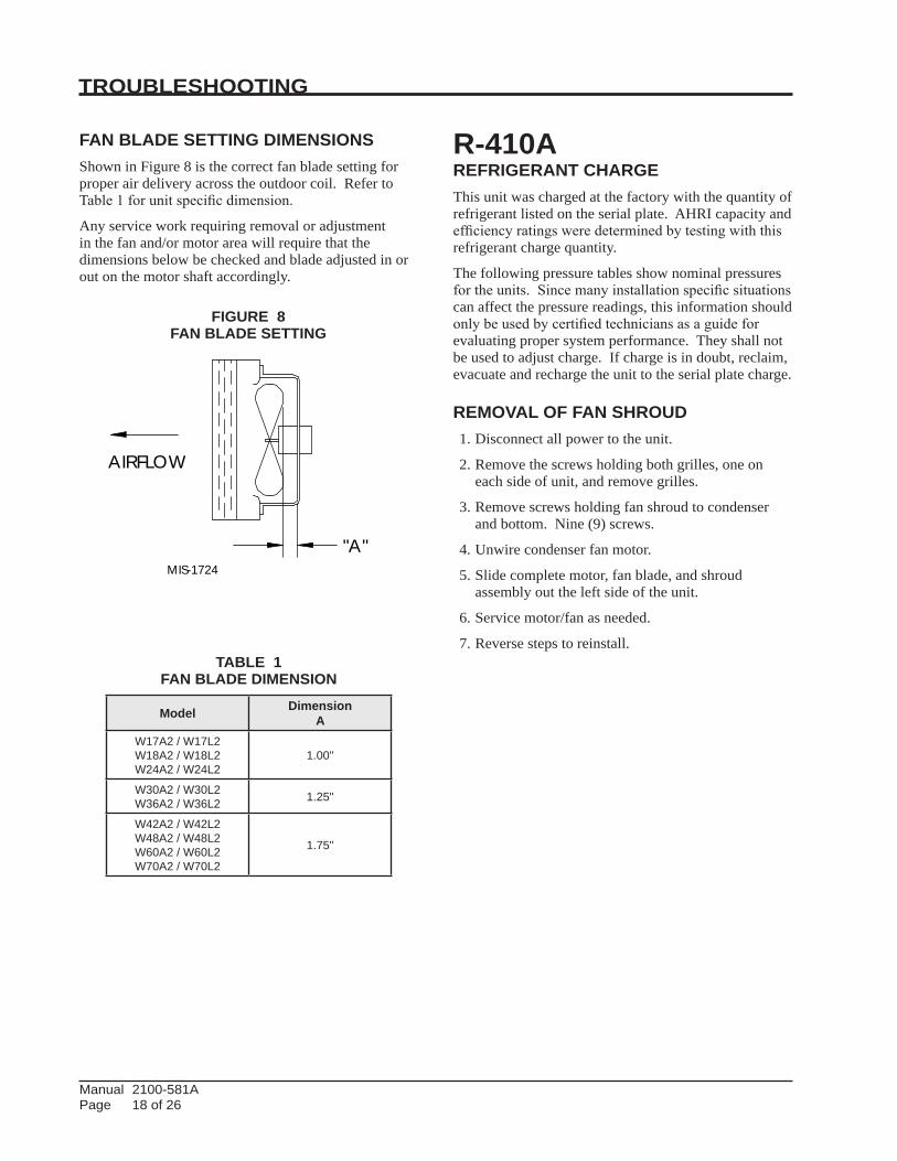
Model DimensionA
W17A2 / W17L2W18A2 / W18L2W24A2 / W24L2
1.00"
W30A2 / W30L2W36A2 / W36L2 1.25"
W42A2 / W42L2W48A2 / W48L2W60A2 / W60L2W70A2 / W70L2
1.75"
FAN BLADE SETTING DIMENSIONSShown in Figure 8 is the correct fan blade setting for proper air delivery across the outdoor coil. Refer to Table 1 for unit specific dimension.
Any service work requiring removal or adjustment in the fan and/or motor area will require that the dimensions below be checked and blade adjusted in or out on the motor shaft accordingly.
Manual 2100-581A Page 19 of 26
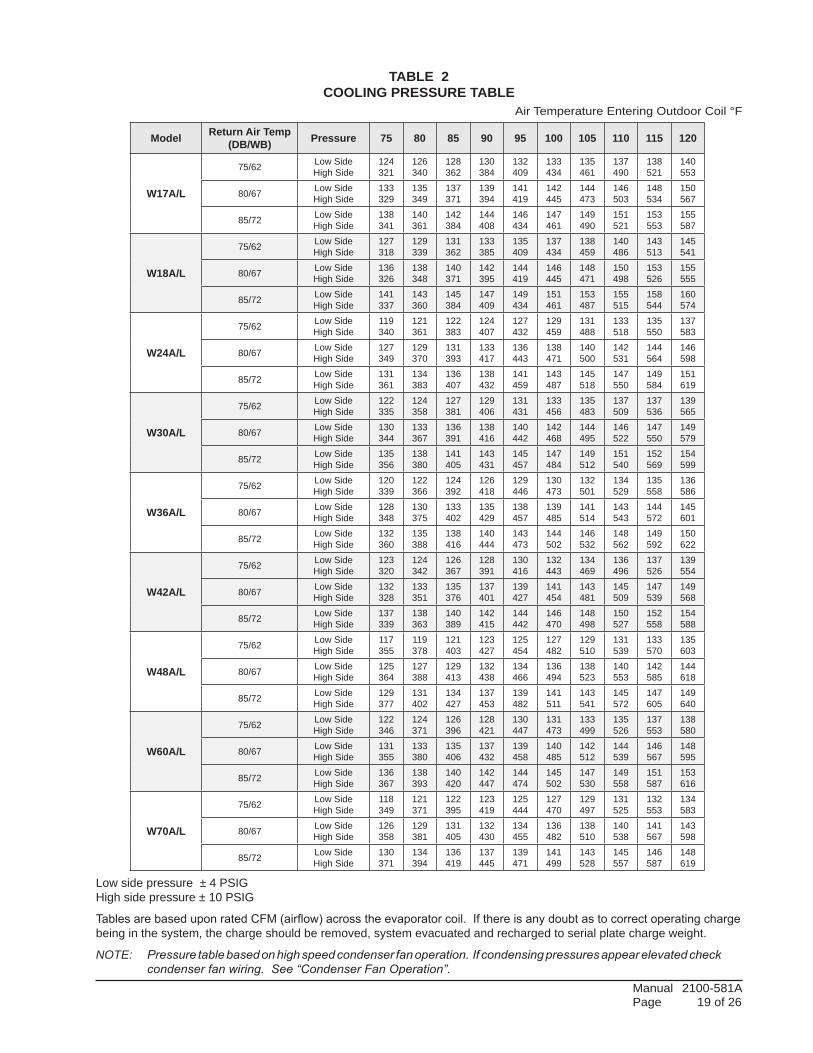
TABLE 2 COOLING PRESSURE TABLE
Air Temperature Entering Outdoor Coil °F
Low side pressure ± 4 PSIG High side pressure ± 10 PSIG
Tables are based upon rated CFM (airflow) across the evaporator coil. If there is any doubt as to correct operating charge being in the system, the charge should be removed, system evacuated and recharged to serial plate charge weight.
NOTE: Pressure table based on high speed condenser fan operation. If condensing pressures appear elevated check condenser fan wiring. See “Condenser Fan Operation”.
Model Return Air Temp (DB/WB) Pressure 75 80 85 90 95 100 105 110 115 120
W17A/L
75/62 Low SideHigh Side
124321
126340
128362
130384
132409
133434
135461
137490
138521
140553
80/67 Low SideHigh Side
133329
135349
137371
139394
141419
142445
144473
146503
148534
150567
85/72 Low SideHigh Side
138341
140361
142384
144408
146434
147461
149490
151521
153553
155587
W18A/L
75/62 Low SideHigh Side
127318
129339
131362
133385
135409
137434
138459
140486
143513
145541
80/67 Low SideHigh Side
136326
138348
140371
142395
144419
146445
148471
150498
153526
155555
85/72 Low SideHigh Side
141337
143360
145384
147409
149434
151461
153487
155515
158544
160574
W24A/L
75/62 Low SideHigh Side
119340
121361
122383
124407
127432
129459
131488
133518
135550
137583
80/67 Low SideHigh Side
127349
129370
131393
133417
136443
138471
140500
142531
144564
146598
85/72 Low SideHigh Side
131361
134383
136407
138432
141459
143487
145518
147550
149584
151619
W30A/L
75/62 Low SideHigh Side
122335
124358
127381
129406
131431
133456
135483
137509
137536
139565
80/67 Low SideHigh Side
130344
133367
136391
138416
140442
142468
144495
146522
147550
149579
85/72 Low SideHigh Side
135356
138380
141405
143431
145457
147484
149512
151540
152569
154599
W36A/L
75/62 Low SideHigh Side
120339
122366
124392
126418
129446
130473
132501
134529
135558
136586
80/67 Low SideHigh Side
128348
130375
133402
135429
138457
139485
141514
143543
144572
145601
85/72 Low SideHigh Side
132360
135388
138416
140444
143473
144502
146532
148562
149592
150622
W42A/L
75/62 Low SideHigh Side
123320
124342
126367
128391
130416
132443
134469
136496
137526
139554
80/67 Low SideHigh Side
132328
133351
135376
137401
139427
141454
143481
145509
147539
149568
85/72 Low SideHigh Side
137339
138363
140389
142415
144442
146470
148498
150527
152558
154588
W48A/L
75/62 Low SideHigh Side
117355
119378
121403
123427
125454
127482
129510
131539
133570
135603
80/67 Low SideHigh Side
125364
127388
129413
132438
134466
136494
138523
140553
142585
144618
85/72 Low SideHigh Side
129377
131402
134427
137453
139482
141511
143541
145572
147605
149640
W60A/L
75/62 Low SideHigh Side
122346
124371
126396
128421
130447
131473
133499
135526
137553
138580
80/67 Low SideHigh Side
131355
133380
135406
137432
139458
140485
142512
144539
146567
148595
85/72 Low SideHigh Side
136367
138393
140420
142447
144474
145502
147530
149558
151587
153616
W70A/L
75/62 Low SideHigh Side
118349
121371
122395
123419
125444
127470
129497
131525
132553
134583
80/67 Low SideHigh Side
126358
129381
131405
132430
134455
136482
138510
140538
141567
143598
85/72 Low SideHigh Side
130371
134394
136419
137445
139471
141499
143528
145557
146587
148619
Manual 2100-581A Page 20 of 26
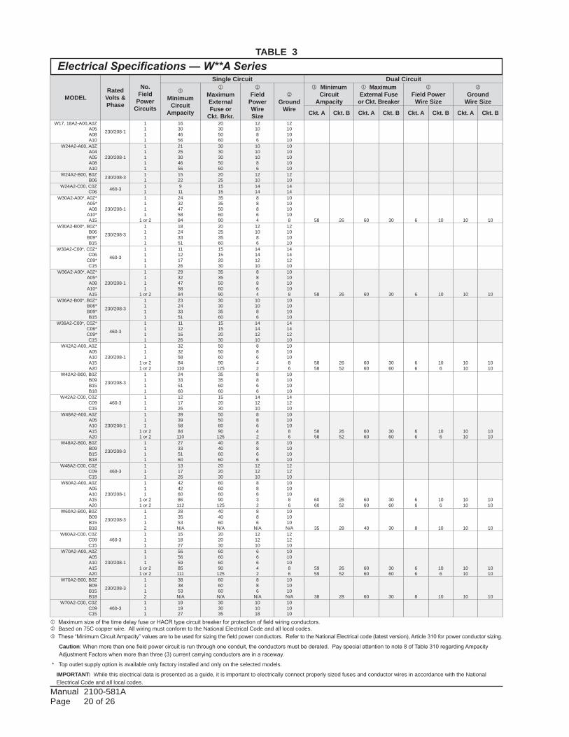
TABLE 3
j Maximum size of the time delay fuse or HACR type circuit breaker for protection of field wiring conductors. Based on 75C copper wire. All wiring must conform to the National Electrical Code and all local codes. These “Minimum Circuit Ampacity” values are to be used for sizing the field power conductors. Refer to the National Electrical code (latest version), Article 310 for power conductor sizing.
Caution: When more than one field power circuit is run through one conduit, the conductors must be derated. Pay special attention to note 8 of Table 310 regarding Ampacity Adjustment Factors when more than three (3) current carrying conductors are in a raceway.
* Top outlet supply option is available only factory installed and only on the selected models.
IMPORTANT: While this electrical data is presented as a guide, it is important to electrically connect properly sized fuses and conductor wires in accordance with the National Electrical Code and all local codes.
Electrical Specifications — W**A Series
MODELRated
Volts & Phase
No. Field
Power Circuits
Single Circuit Dual Circuit
Minimum
Circuit Ampacity
jMaximum External Fuse or
Ckt. Brkr.
Field
Power Wire Size
Ground
Wire
Minimum Circuit
Ampacity
j MaximumExternal Fuse
or Ckt. Breaker
Field Power
Wire Size
Ground
Wire Size
Ckt. A Ckt. B Ckt. A Ckt. B Ckt. A Ckt. B Ckt. A Ckt. BW17, 18A2-A00,A0Z
A05A08A10
230/208-1
1111
16304656
20305060
121086
12101010
W24A2-A00, A0ZA04A05A08A10
230/208-1
11111
2125304656
3030305060
10101086
1010101010
W24A2-B00, B0ZB06 230/208-3 1
11522
2025
1210
1210
W24A2-C00, C0ZC06 460-3 1
1911
1515
1414
1414
W30A2-A00*, A0Z*A05*A08
A10*A15
230/208-1
1111
1 or 2
2432475884
3535506090
88864
101010108 58 26 60 30 6 10 10 10
W30A2-B00*, B0Z*B06
B09*B15
230/208-3
1111
18243351
20253560
121086
12101010
W30A2-C00*, C0Z*C06
C09*C15
460-3
1111
11121726
15152030
14141210
14141210
W36A2-A00*, A0Z*A05*A08
A10*A15
230/208-1
1111
1 or 2
2932475884
3535506090
88864
101010108 58 26 60 30 6 10 10 10
W36A2-B00*, B0Z*B06*B09*B15
230/208-3
1111
23243351
30303560
101086
10101010
W36A2-C00*, C0Z*C06*C09*C15
460-3
1111
11121626
15152030
14141210
14141210
W42A2-A00, A0ZA05A10A15A20
230/208-1
111
1 or 21 or 2
32325884110
50506090125
88642
10101086
5858
2652
6060
3060
66
106
1010
1010
W42A2-B00, B0ZB09B15B18
230/208-3
1111
24335160
35356060
8866
10101010
W42A2-C00, C0ZC09C15
460-3111
121726
152030
141210
141210
W48A2-A00, A0ZA05A10A15A20
230/208-1
111
1 or 21 or 2
39395884110
50506090125
88642
10101086
5858
2652
6060
3060
66
106
1010
1010
W48A2-B00, B0ZB09B15B18
230/208-3
1111
27335160
40406060
8866
10101010
W48A2-C00, C0ZC09C15
460-3111
131726
202030
121210
121210
W60A2-A00, A0ZA05A10A15A20
230/208-1
111
1 or 21 or 2
42426086112
60606090125
88632
10101086
6060
2652
6060
3060
66
106
1010
1010
W60A2-B00, B0ZB09B15B18
230/208-3
1112
283553N/A
404060N/A
886
N/A
101010N/A 35 28 40 30 8 10 10 10
W60A2-C00, C0ZC09C15
460-3111
151827
202030
121210
121210
W70A2-A00, A0ZA05A10A15A20
230/208-1
111
1 or 21 or 2
56565985111
60606090125
66642
10101086
5959
2652
6060
3060
66
106
1010
1010
W70A2-B00, B0ZB09B15B18
230/208-3
1112
383853N/A
606060N/A
886
N/A
101010N/A 38 28 60 30 8 10 10 10
W70A2-C00, C0ZC09C15
460-3111
191927
303035
101018
101010
Manual 2100-581A Page 21 of 26
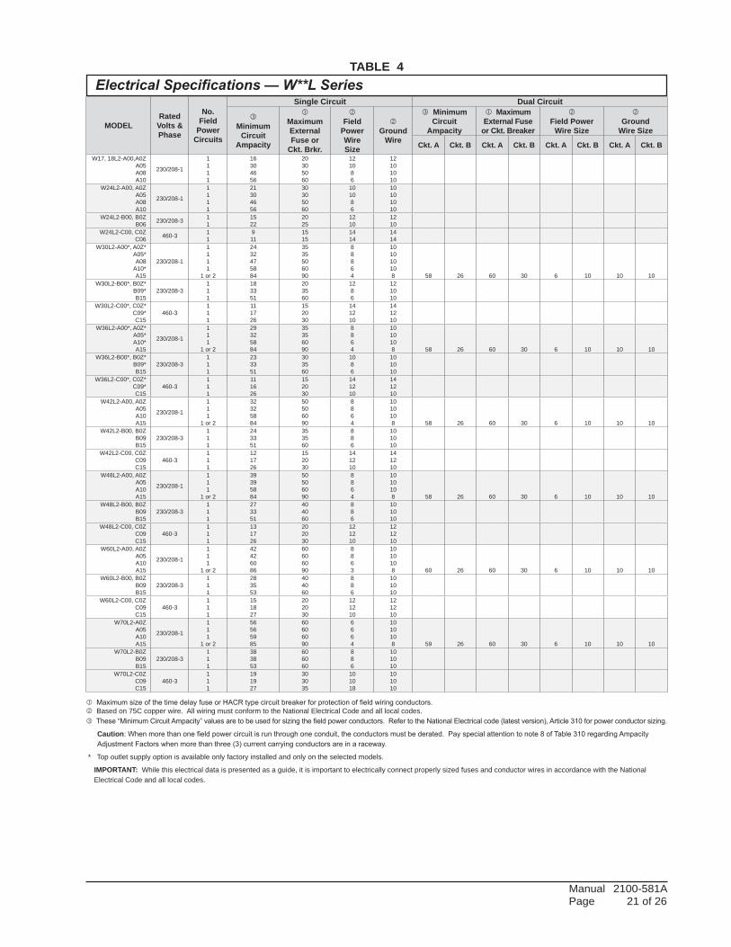
TABLE 4
j Maximum size of the time delay fuse or HACR type circuit breaker for protection of field wiring conductors. Based on 75C copper wire. All wiring must conform to the National Electrical Code and all local codes. These “Minimum Circuit Ampacity” values are to be used for sizing the field power conductors. Refer to the National Electrical code (latest version), Article 310 for power conductor sizing.
Caution: When more than one field power circuit is run through one conduit, the conductors must be derated. Pay special attention to note 8 of Table 310 regarding Ampacity Adjustment Factors when more than three (3) current carrying conductors are in a raceway.
* Top outlet supply option is available only factory installed and only on the selected models.
IMPORTANT: While this electrical data is presented as a guide, it is important to electrically connect properly sized fuses and conductor wires in accordance with the National Electrical Code and all local codes.
Electrical Specifications — W**L Series
MODELRated
Volts & Phase
No. Field
Power Circuits
Single Circuit Dual Circuit
Minimum
Circuit Ampacity
jMaximum External Fuse or
Ckt. Brkr.
Field
Power Wire Size
Ground
Wire
Minimum Circuit
Ampacity
j MaximumExternal Fuse
or Ckt. Breaker
Field Power
Wire Size
Ground
Wire Size
Ckt. A Ckt. B Ckt. A Ckt. B Ckt. A Ckt. B Ckt. A Ckt. BW17, 18L2-A00,A0Z
A05A08A10
230/208-1
1111
16304656
20305060
121086
12101010
W24L2-A00, A0ZA05A08A10
230/208-1
1111
21304656
30305060
101086
10101010
W24L2-B00, B0ZB06 230/208-3 1
11522
2025
1210
1210
W24L2-C00, C0ZC06 460-3 1
1911
1515
1414
1414
W30L2-A00*, A0Z*A05*A08
A10*A15
230/208-1
1111
1 or 2
2432475884
3535506090
88864
101010108 58 26 60 30 6 10 10 10
W30L2-B00*, B0Z*B09*B15
230/208-3111
183351
203560
1286
121010
W30L2-C00*, C0Z*C09*C15
460-3111
111726
152030
141210
141210
W36L2-A00*, A0Z*A05*A10*A15
230/208-1
111
1 or 2
29325884
35356090
8864
1010108 58 26 60 30 6 10 10 10
W36L2-B00*, B0Z*B09*B15
230/208-3111
233351
303560
1086
101010
W36L2-C00*, C0Z*C09*C15
460-3111
111626
152030
141210
141210
W42L2-A00, A0ZA05A10A15
230/208-1
111
1 or 2
32325884
50506090
8864
1010108 58 26 60 30 6 10 10 10
W42L2-B00, B0ZB09B15
230/208-3111
243351
353560
886
101010
W42L2-C00, C0ZC09C15
460-3111
121726
152030
141210
141210
W48L2-A00, A0ZA05A10A15
230/208-1
111
1 or 2
39395884
50506090
8864
1010108 58 26 60 30 6 10 10 10
W48L2-B00, B0ZB09B15
230/208-3111
273351
404060
886
101010
W48L2-C00, C0ZC09C15
460-3111
131726
202030
121210
121210
W60L2-A00, A0ZA05A10A15
230/208-1
111
1 or 2
42426086
60606090
8863
1010108 60 26 60 30 6 10 10 10
W60L2-B00, B0ZB09B15
230/208-3111
283553
404060
886
101010
W60L2-C00, C0ZC09C15
460-3111
151827
202030
121210
121210
W70L2-A0ZA05A10A15
230/208-1
111
1 or 2
56565985
60606090
6664
1010108 59 26 60 30 6 10 10 10
W70L2-B0ZB09B15
230/208-3111
383853
606060
886
101010
W70L2-C0ZC09C15
460-3111
191927
303035
101018
101010
Manual 2100-581A Page 22 of 26
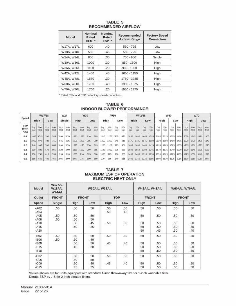
TABLE 5RECOMMENDED AIRFLOW
TABLE 6INDOOR BLOWER PERFORMANCE
TABLE 7MAXIMUM ESP OF OPERATION
ELECTRIC HEAT ONLY
Values shown are for units equipped with standard 1-inch throwaway filter or 1-inch washable filter.Derate ESP by .15 for 2-inch pleated filters.
ModelNominal
Rated CFM *
Nominal Rated ESP *
Recommended Airflow Range
Factory Speed Connection
W17A, W17L 600 .40 550 - 725 Low
W18A, W18L 550 .45 550 - 725 Low
W24A, W24L 800 .30 700 - 950 Single
W30A, W30L 1000 .30 850 - 1300 High
W36A, W36L 1100 .20 930 - 1350 High
W42A, W42L 1400 .45 1600 - 1150 High
W48A, W48L 1550 .30 1750 - 1285 High
W60A, W60L 1700 .40 1950 - 1375 High
W70A, W70L 1700 .20 1950 - 1375 High
SpeedW17/18 W24 W30 W36 W42/48 W60 W70
High Low Single High Low High Low High Low High Low High Low
ESP(Inch H20)
Dry Coil
Wet Coil
Dry Coil
Wet Coil
Dry Coil
Wet Coil
Dry Coil
Wet Coil
Dry Coil
Wet Coil
Dry Coil
Wet Coil
Dry Coil
Wet Coil
Dry Coil
Wet Coil
Dry Coil
Wet Coil
Dry Coil
Wet Coil
Dry Coil
Wet Coil
Dry Coil
Wet Coil
Dry Coil
Wet Coil
0.0 1045 1025 760 745 990 970 1370 1285 910 885 1415 1275 955 925 1850 1800 1605 1555 2080 2015 1505 1460 2050 1845 1490 1400
0.1 1010 970 730 715 945 925 1305 1225 885 860 1350 1215 945 915 1775 1725 1545 1500 2020 1960 1450 1405 1970 1770 1425 1340
0.2 940 905 700 685 890 870 1225 1135 850 815 1265 1125 925 900 1685 1640 1460 1415 1925 1865 1395 1355 1905 1700 1375 1295
0.3 860 830 670 655 820 800 1115 1020 790 755 1190 1060 875 850 1590 1550 1390 1345 1870 1815 1340 1300 1830 1645 1225 1150
0.4 780 750 610 595 735 720 1005 910 695 660 1085 975 780 755 1495 1460 1310 1270 1755 1705 1225 1185 1725 1550 1140 1070
0.5 665 640 485 455 605 590 865 775 590 560 970 865 640 615 1400 1365 1225 1185 1660 1610 1125 1085 1500 1350 1050 985
ModelW17A/L,W18A/L, W24A/L
W30A/L, W36A/L W42A/L, W48A/L W60A/L, W70A/L
Outlet FRONT FRONT TOP FRONT FRONTSpeed Single High Low High Low High Low High Low-A0Z-A04-A05-A08-A10-A15-A20
.50
.50
.50
.50
.50
.50
.50
.40
.50
.50
.50
.45
.35
.50
.50
.50
.50
.45
.35
.50
.50
.50
.50
.50
.50
.50
.50
.50
.45
.50
.50
.50
.50
.50
.50
.50
.50
.50
.40
-B0Z-B06-B09-B15-B18
.50
.50.50.50.50.45
.50
.40
.50
.30
.50
.45
.50
.40
.50
.50
.50
.50
.50
.50
.50
.50
.50
.50
.50
.50
.50
.50
.50
.50
-C0Z-C06-C09-C15
.50
.50
.50
.45
.50
.50
.40
.35
.50
.45
.50
.40
.50
.50
.50
.50
.50
.50
.50
.50
.50
.50
.50
.50
* Rated CFM and ESP on factory speed connection.
Manual 2100-581A Page 23 of 26
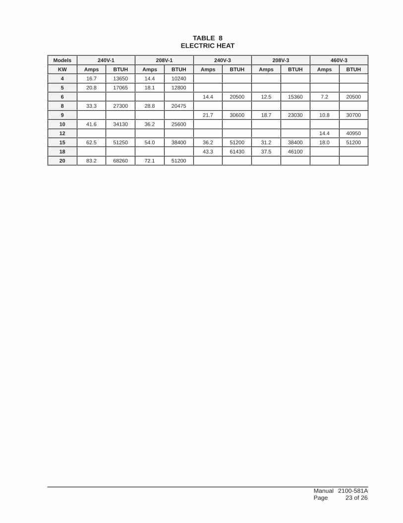
TABLE 8ELECTRIC HEAT
Models 240V-1 208V-1 240V-3 208V-3 460V-3KW Amps BTUH Amps BTUH Amps BTUH Amps BTUH Amps BTUH4 16.7 13650 14.4 10240
5 20.8 17065 18.1 12800
6 14.4 20500 12.5 15360 7.2 20500
8 33.3 27300 28.8 20475
9 21.7 30600 18.7 23030 10.8 30700
10 41.6 34130 36.2 25600
12 14.4 40950
15 62.5 51250 54.0 38400 36.2 51200 31.2 38400 18.0 51200
18 43.3 61430 37.5 46100
20 83.2 68260 72.1 51200
Manual 2100-581A Page 24 of 26
W17
/18A
2-A
W24
A2-
A
W24
A2-
B
W24
A2-
C
W30
A2-
A
W30
A2-
B
W30
A2-
C
W36
A2-
A
W36
A2-
B
W36
A2-
C
W42
A2-
A
W42
A2-
B
W42
A2-
C
W48
A2-
A
W48
A2-
B
W48
A2-
C
W60
A2-
A
W60
A2-
B
W60
A2-
C
W70
A2-
A
W70
A2-
B
W70
A2-
C
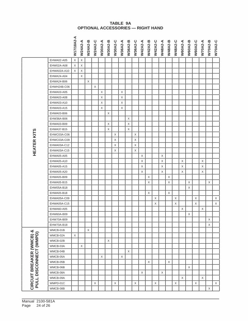
TABLE 9AOPTIONAL ACCESSORIES — RIGHT HAND
EHWA02-A05 X X
EHW02A-A08 X X
EHWA02A-A10 X X
EHWA24-A04 X
EHWA24-B06 X
EHWH24B-C06 X
EHWA03-A05 X X
EHWA03-A08 X X
EHWA03-A10 X X
EHWA03-A15 X X
EHWA03-B06 X
EHW36A-B06 X
EHWA03-B09 X X
EHWA37-B15 X X
EHWC03A-C06 X X
EHWC03A-C09 X X
EHWA03A-C12 X X
EHWA03A-C15 X X
EHWA05-A05 X X
EHWA05-A10 X X X X
EHWA05-A15 X X X X
EHWA05-A20 X X X X
EHWA05-B09 X X
EHWA05-B15 X X X X
EHW05A-B18 X
EHWA05-B18 X X
EHWA05A-C09 X X X X
EHWA05A-C15 X X X X
EHWA60-A05 X X
EHW60A-B09 X
EHW70A-B09 X
EHW70A-B18 X
WMCB-01B X
WMCB-02A X
WMCB-02B X
WMCB-03A X
WMCB-04B X
WMCB-05A X X
WMCB-05B X X
WMCB-06B X
WMCB-08A X X
WMCB-09A X X
WMPD-01C X X X X X X X
WMCB-08B X
HEA
TER
KIT
SC
IRC
UIT
BR
EAK
ER (W
MC
B) &
PU
LL D
ISC
ON
NEC
T (W
MPD
)
Manual 2100-581A Page 25 of 26
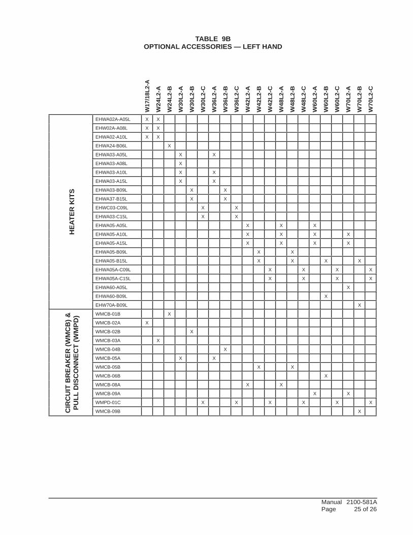
TABLE 9BOPTIONAL ACCESSORIES — LEFT HAND
W17
/18L
2-A
W24
L2-A
W24
L2-B
W30
L2-A
W30
L2-B
W30
L2-C
W36
L2-A
W36
L2-B
W36
L2-C
W42
L2-A
W42
L2-B
W42
L2-C
W48
L2-A
W48
L2-B
W48
L2-C
W60
L2-A
W60
L2-B
W60
L2-C
W70
L2-A
W70
L2-B
W70
L2-C
EHWA02A-A05L X X
EHW02A-A08L X X
EHWA02-A10L X X
EHWA24-B06L X
EHWA03-A05L X X
EHWA03-A08L X
EHWA03-A10L X X
EHWA03-A15L X X
EHWA03-B09L X X
EHWA37-B15L X X
EHWC03-C09L X X
EHWA03-C15L X X
EHWA05-A05L X X X
EHWA05-A10L X X X X
EHWA05-A15L X X X X
EHWA05-B09L X X
EHWA05-B15L X X X X
EHWA05A-C09L X X X X
EHWA05A-C15L X X X X
EHWA60-A05L X
EHWA60-B09L X
EHW70A-B09L X
WMCB-01B X
WMCB-02A X
WMCB-02B X
WMCB-03A X
WMCB-04B X
WMCB-05A X X
WMCB-05B X X
WMCB-06B X
WMCB-08A X X
WMCB-09A X X
WMPD-01C X X X X X X
WMCB-09B X
HEA
TER
KIT
SC
IRC
UIT
BR
EAK
ER (W
MC
B) &
PU
LL D
ISC
ON
NEC
T (W
MPD
)
Manual 2100-581A Page 26 of 26
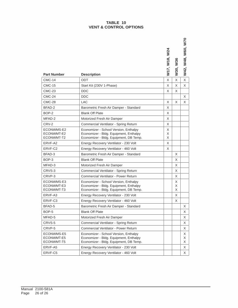
TABLE 10VENT & CONTROL OPTIONS
W17
, W18
, W24
W30
, W36
W42
, W48
, W60
, W70
Part Number DescriptionCMC-14 ODT X X X
CMC-15 Start Kit (230V 1-Phase) X X X
CMC-23 DDC X X
CMC-24 DDC X
CMC-28 LAC X X X
BFAD-2 Barometric Fresh Air Damper - Standard X
BOP-2 Blank Off Plate X
MFAD-2 Motorized Fresh Air Damper X
CRV-2 Commercial Ventilator - Spring Return X
ECONWMS-E2ECONWMT-E2ECONWMT-T2
Economizer - School Version, EnthalpyEconomizer - Bldg. Equipment, EnthalpyEconomizer - Bldg. Equipment, DB Temp.
XXX
ERVF-A2 Energy Recovery Ventilator - 230 Volt X
ERVF-C2 Energy Recovery Ventilator - 460 Volt X
BFAD-3 Barometric Fresh Air Damper - Standard X
BOP-3 Blank Off Plate X
MFAD-3 Motorized Fresh Air Damper X
CRVS-3 Commercial Ventilator - Spring Return X
CRVP-3 Commercial Ventilator - Power Return X
ECONWMS-E3ECONWMT-E3ECONWMT-T3
Economizer - School Version, EnthalpyEconomizer - Bldg. Equipment, EnthalpyEconomizer - Bldg. Equipment, DB Temp.
XXX
ERVF-A3 Energy Recovery Ventilator - 230 Volt X
ERVF-C3 Energy Recovery Ventilator - 460 Volt X
BFAD-5 Barometric Fresh Air Damper - Standard X
BOP-5 Blank Off Plate X
MFAD-5 Motorized Fresh Air Damper X
CRVS-5 Commercial Ventilator - Spring Return X
CRVP-5 Commercial Ventilator - Power Return X
ECONWMS-E5ECONWMT-E5ECONWMT-T5
Economizer - School Version, EnthalpyEconomizer - Bldg. Equipment, EnthalpyEconomizer - Bldg. Equipment, DB Temp.
XXX
ERVF-A5 Energy Recovery Ventilator - 230 Volt X
ERVF-C5 Energy Recovery Ventilator - 460 Volt X