INSTALLATION AND USER INSTRUCTIONSinstallation and user instructions hot water storage heaters...
28
INSTALLATION AND USER INSTRUCTIONS HOT WATER STORAGE HEATERS UNITED KINGDOM / IRELAND MODELS BRV 30 NORS G BRV 40 NORS G BRV 50 NRRT G
Transcript of INSTALLATION AND USER INSTRUCTIONSinstallation and user instructions hot water storage heaters...

INSTALLATION AND USERINSTRUCTIONS
HOT WATER STORAGE HEATERS
UNITED KINGDOM / IRELAND
MODELS BRV 30 NORS GBRV 40 NORS GBRV 50 NRRT G

2
Read these installation instructions first before installing the appliance. Carefully readthe user instructions before igniting the appliance. Failure to follow these instructionsmay lead to risk of explosion and/or fire and could cause material damage and/or bodilyharm.Installation and commissioning should be carried out by a qualified competent installer.The type of gas and the value at which the appliance is set standard in the factory areregistered on the rating plate. The appliance may only be installed in a room if this roommeets the ventilation requirements.
BSS GROUP PLC accepts no responsibility for warranty, service and/orproduct liability in case of unauthorized alterations, product modifications orrepair.

3
CONTENTS PAGE
1. General. ............................................................................................................ 41.1 Introduction ......................................................................................................... 41.2 Technical safety equipment ................................................................................ 61.2.1 Gas control block ................................................................................................ 61.2.2 Combustion products discharge safety device .................................................. 61.3 Technical information .......................................................................................... 81.3.1 Dimensions ......................................................................................................... 81.3.2 Technical data .................................................................................................. 10
2. For the installer. ........................................................................................... 112.1 Installation instructions ...................................................................................... 112.1.1 Installation ......................................................................................................... 112.1.2 Water circulation system .................................................................................. 112.1.3 Gas connection ................................................................................................ 122.1.4 Flue system ...................................................................................................... 122.1.5 Flue down draught safety device ..................................................................... 132.2 Commissioning .................................................................................................. 142.2.1 Filling the water heater ..................................................................................... 142.2.2 Putting into operation ........................................................................................ 142.2.3 Removing and replacing the inner door ............................................................. 152.3 Pilot adjustment ................................................................................................. 152.4 Putting out of operation ..................................................................................... 152.5 Temperature regulation ..................................................................................... 162.6 Setting the nominal heat input ........................................................................... 172.7 Conversion procedure ...................................................................................... 182.8 Maintenance ..................................................................................................... 192.8.1 Sacrificial anode ............................................................................................... 192.8.2 Cleaning ............................................................................................................ 192.8.3 Decalcification .................................................................................................. 202.8.4 Spare parts ....................................................................................................... 202.9 Inlet combination ............................................................................................... 202.10 Fault finding ...................................................................................................... 202.10.1 Safety thermostat ............................................................................................. 202.10.2 Flue down draught safety device ..................................................................... 212.10.3 Hot water temperature too low ......................................................................... 212.10.4 Hot water temperature too high ........................................................................ 212.10.5 Possible water leakage ..................................................................................... 212.11 Gas smell .......................................................................................................... 212.12 Condensation .................................................................................................... 21
3. For the user. .................................................................................................. 213.1 Commissioning .................................................................................................. 213.1.1 Filling the water heater ..................................................................................... 213.1.2 Putting into operation ........................................................................................ 223.1.3 Use ................................................................................................................... 223.1.4 Putting out of operation ..................................................................................... 223.1.5 Maintenance ..................................................................................................... 223.2 Fault finding ...................................................................................................... 23
4. Guarantee. ..................................................................................................... 25
4
1. GENERAL
1.1 Introduction
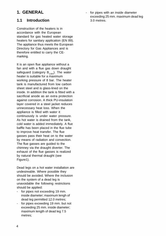
Construction of the heaters is inaccordance with the Europeanstandard for gas heated water storageheaters for sanitary application (EN 89).The appliance thus meets the EuropeanDirectory for Gas Appliances and istherefore entitled to carry the CE-marking.
It is an open flue appliance without afan and with a flue gas down draughtsafeguard (category B11BS). The waterheater is suitable for a maximumworking pressure of 8 bar. The heatertank is manufactured from low carbonsheet steel and is glass-lined on theinside. In addition the tank is fitted with asacrificial anode as an extra protectionagainst corrosion. A thick PU-insulationlayer covered in a steel jacket reducesunnecessary heat loss. When theappliance is filled with water itcontinuously is under water pressure.As hot water is drained from the tank,cold water is added immediately. A fluebaffle has been placed in the flue tubeto improve heat transfer. The fluegasses pass their heat on to the waterby means of radiation and convection.The flue gasses are guided to thechimney via the draught diverter. Theexhaust of the flue gasses is realizedby natural thermal draught (seeFigure1).
Dead legs on a hot water installation areundesireable. Where possible theyshould be avoided. Where the inclusionon the system of a dead leg isunavoidable the following restrictionsshould be applied:- for pipes not exceeding 19 mm.
inside diameter; maximum lengh ofdead leg permitted 12.0 metres;
- for pipes exceeding 19 mm. but notexceeding 25 mm. inside diameter;maximum length of dead leg 7.5metres;
- for pipes with an inside diameterexceeding 25 mm. maximum dead leg3.0 metres.
5
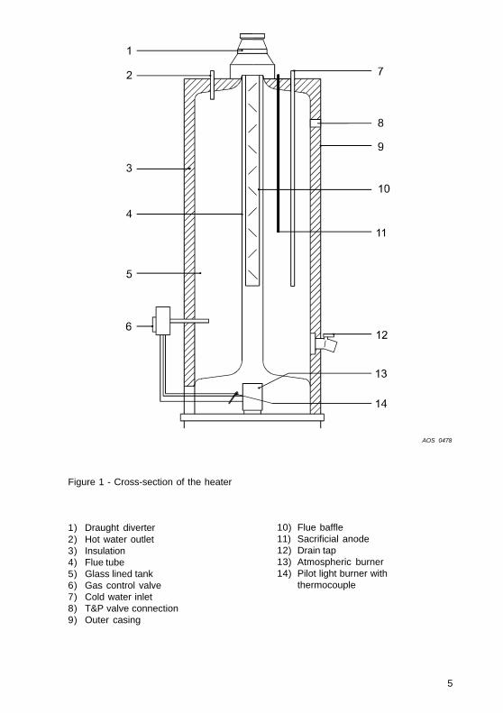
1) Draught diverter2) Hot water outlet3) Insulation4) Flue tube5) Glass lined tank6) Gas control valve7) Cold water inlet8) T&P valve connection9) Outer casing
Figure 1 - Cross-section of the heater
10) Flue baffle11) Sacrificial anode12) Drain tap13) Atmospheric burner14) Pilot light burner with
thermocouple
AOS 0478

6
1.2 Technical safetyequipment
1.2.1 Gas control valveThe water heater has been fitted with agas control block consisting of athermo-electrical pilot flame safeguard,pilot flame pressure regulator, burnerpressure regulator, a control thermostat(adjustable between 30°C and 71°C)and a safety thermostat (82°C). Thisgas control block with its simple andsecure control respectively switchesthe gas supply to the main burner on oroff.This gas control block is suitable forgasses from the first, second and thirdgas family. The maximum inlet pressureis 50 mbar.
1.2.2 Combustion productsdischarge safety device
The water heater has been fitted with acombustion products discharge safetydevice. It is the function of the safetydevice to prevent flue gasses from thewater heater entering the room wherethe water heater has been placed,instead of passing through the flue tooutside atmosphere. The gas supply isdisconnected as soon as the device isactivated by hot gasses flowing overthe sensor.After the cause of the re-entry of fluegasses has been traced the device canbe put back into operation by pressingits reset button.If this faillure occurs frequently, thisindicates that the flue suffers fromdown draught conditions. It isrecommended that a competent personcarry out the necessary remendialaction.
ImportantThe combustion products dis-charge safety device should neverbe put out of operation. Re-entry offlue gasses to the building couldbe harmful and cause poisoning ordeath.

7
Figure 2 - Combustion productsdischarge safety device with gascontrol valve
1) Combustion products dischargesafety device thermostat
2) Sensor Combustion productsdischarge safety devicethermostat
3) Thermocouple with built-ininterrupter
4) Thermocouple5) Gas control block6) Reset button7) Pilot burner8) Temperature regulator knob
AOS 0479

8
1.3 Technical information
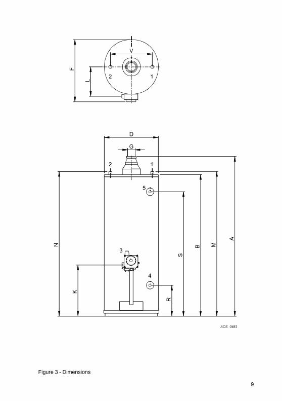
1.3.1 DimensionsThese water heaters are only suitablefor a flue tube with minimal theannounced diameter (dimension G).
Dimen-sions BRV 30 NORS BRV 40 NORS BRV 50 NRRT
(see draw.3)
A 1280 1370 1670B 1120 1210 1540D 465 515 515F 545 595 605G 80 80 100K 325 325 380L 270 295 395M 1160 1250 1590N 1160 1250 1590R 230 230 255S 945 1030 1380V 205 205 2051 Cold water inlet2 Hot water outlet3 Gas control valve4 Drain tap5 T&P valve tapping
All dimensions are given in mm.(rounded off on 5 mm).See figure 3.
9
Figure 3 - Dimensions
AOS 0481

10
Storage capacity litres 109 144 181
Water connections ** - 3/4" - 14 NPT 3/4" - 14 NPT 3/4" - 14 NPT
Gas connection - ISO 7/1 Rp 1/2 ISO 7/1 Rp 1/2 ISO 7/1 Rp 1/2
Drain valve - 3/4" - 14 NPT 3/4" - 14 NPT 3/4" - 14 NPT
Anode - 3/4" - 14 NPT 3/4" - 14 NPT 3/4" - 14 NPT
T&P-plug - 3/4" - 14 NPT 3/4" - 14 NPT 3/4" - 14 NPT
Maximum operating pressure bar 8 8 8
Empty weight kg 47 52 75
* Gas consumption at 1013,25 mbar and 15°C
** For a leak proof connection to an NPT thread, a coupling with threads to ISO 228/1 can be used.
DATA NATURAL GAS G20 - 20 mbar:
Nominal load (gross) k W 9.3 11.3 18.3
Nominal capacity k W 7.4 9.0 14.0
Supply pressure mbar 20 20 20
Burner pressure mbar 12.5 12.5 10.5
Gas consumption * m3/h 0.9 1.1 1.7
Diameter main orifice mm 2.35 2.60 3.50
Diameter pilot orifice mm 2 x 0.27 2 x 0.27 2 x 0.27
Heating time ∆T= 44 K min. 45 49 40
DATA BUTANE G30 - 28/30 mbar:
Nominal load (gross) kW 10.1 12.2 17.6
Supply pressure mbar 30 30 30
Burner pressure mbar 30 30 30
Gas consumption * kg/h 0.7 0.9 1.3
Diameter main orifice mm 1.40 1.50 1.95
Diameter pilot orifice mm 0.22 0.22 0.22
DATA PROPANE G31 - 37 mbar
Nominal load (gross) kW 9.3 11.7 15.8
Supply pressure mbar 37 37 37
Burner pressure mbar 37 37 37
Gas consumption * kg/h 0.7 0.8 1.3
Diameter main orifice mm 1.40 1.50 1.95
Diameter pilot orifice mm 0.22 0.22 0.22
GENERAL
1.3.2 Technical dataDevice category: II2H3+
BRV 50 NRRTDESCRIPTION unit BRV 30 NORS BRV 40 NORS

11
2. FOR THE INSTALLER
2.1 Installation instructions
This water heater must be fitted in alocation which will permit the provisionof an approved flue system andadequate ventilation.
A service clearance of 15 cm at thesides and rear of the unit and 60 cm atthe front of the unit should be allowedfor ease of servicing. Adequatedistance must be allowed between thetop of the unit and any obstruction orceiling to allow the flue baffle andanode to be inspected, cleaned or in thecase of the anode replaced ifnecessary.
The water heater must stand on a levelsurface resistant to heat and withsufficient strength to support the weightof the unit when full of water.
This water heater must not be installedin a bath room, bedroom or in a cup-board opening on to such rooms. Thiswater heater must not be installed inany area where flamable materials areused or stored.
Insufficient ventilation may give rise to arisk of fire, explosion or suffocation. Ifin doubt consult the national and localregulations governing the installation ofgas appliances or your local British gasservice department.
2.1.1 InstallationThe installation of this water heatershould be carried out by a suitablyqualified competent person. It is acriminal offence for unqualified personsto install gas equipment.
Installation should be carried out inaccordance with all local authority andbuilding regulations, local waterauthority and fire regulations and thefollowing British standards: 5440, 5546,6644, 6700, 6798 and 6891.
Some chemicals produce vapourswhich can cause rapid failure ofthermocouples, burners and storagetanks if they are drawn into thecombustion air supply.Therefore if this water heater willbe used to supply hot water to:- hairdressers,- dry cleaners- industrial degreasing processesor
any other area where compoundscontaining halogens are used andstored, care should be taken that allprimary and secondary air is drawnfrom outside atmosphere free ofsuch contaminents.
For further advise contact BSS GROUPPLC.
2.1.2 Water circulation system'BSS GROUP PLC' are suitable forconnection to vented, unvented andpumped pressurised systems. In eachcase appropriate valves and fittingsshould be used to ensure the systemcomplies with the requirements of thewater by laws, and appropriate buildingregulations.When fitting it is essential the rules of'good practice' are applied at all stagesof installation.
Vented systemsIf the water heater is to be connected toa cold feed tank or cistern the hot watersupply pipe must include an open ventwhich discharges over the cold feedcistern. The cold feed cistern must havean actual capacity of greater volumethan the hourly recovery rate of thewater heater(s) which it supplies.Theminimum actual capacity is 50 gallons or227 litres.
UnventedTo install an 'BSS GROUP PLC' on anunvented cold water supply system akit of valves and fittings listed by thewater research centre and complyingwith part G3 of the current buildingregulations should be used. Installation
12
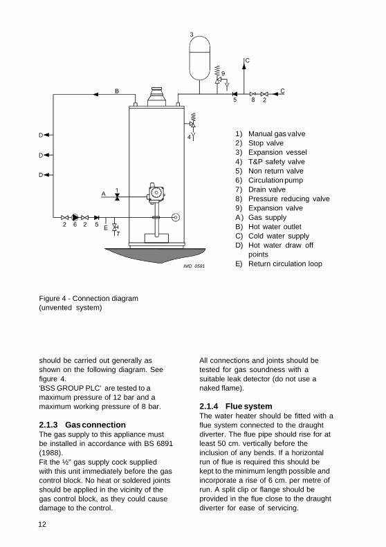
All connections and joints should betested for gas soundness with asuitable leak detector (do not use anaked flame).
2.1.4 Flue systemThe water heater should be fitted with aflue system connected to the draughtdiverter. The flue pipe should rise for atleast 50 cm. vertically before theinclusion of any bends. If a horizontalrun of flue is required this should bekept to the minimum length possible andincorporate a rise of 6 cm. per metre ofrun. A split clip or flange should beprovided in the flue close to the draughtdiverter for ease of servicing.
should be carried out generally asshown on the following diagram. Seefigure 4.'BSS GROUP PLC' are tested to amaximum pressure of 12 bar and amaximum working pressure of 8 bar.
2.1.3 Gas connectionThe gas supply to this appliance mustbe installed in accordance with BS 6891(1988).Fit the ½" gas supply cock suppliedwith this unit immediately before the gascontrol block. No heat or soldered jointsshould be applied in the vicinity of thegas control block, as they could causedamage to the control.
1) Manual gas valve2) Stop valve3) Expansion vessel4) T&P safety valve5) Non return valve6) Circulation pump7) Drain valve8) Pressure reducing valve9) Expansion valveA) Gas supplyB) Hot water outletC) Cold water supplyD) Hot water draw off
pointsE) Return circulation loop
Figure 4 - Connection diagram(unvented system)
IMD 0581

13
All flue materials should be corrosionresistant i.e. stainless steel orgalvanised and must include a testedand approved terminal to BS 5440 part I.If the flue passes through anycombustible material measures must betaken to protect against the possibility offire.All flues must terminate in free air spaceapprox. 1.5 metres from any verticalsurface of structure i.e. chimneystacks, roof parapets, etc. If an existingchimney or flue is to be used this shouldbe swept clean and be free of debrisbefore an approved liner is installed andconnected to the water heater.
2.1.5 Flue down draught safetydevice
The draught diverter has already beenprovided with a temperature probe exfactory for signalling returning fluegases. The probe of the down draughtsupervision must remain installed onthe draught hood.
Connect the slide connectors of thedown draught supervision to thethermocouple (see Figure 5) and installthe head of the down draughtsupervision in the bracket; see Figure5. The draught hood must be positionedin its normal place with the temperatureprobe at the front of the boiler. Passthe wiring of the temperature probethrough the cable duct.
NoteThe screws with which the downdraught supervision has been mountedin the bracket are already in thebracket.
ImportantThe capillary tube of the draughtdiverter should not show any sharpbuckles or kinks as this may result indamage and subsequent failure of thewater heater
The T.R.S. should never be put outof operation. The reentry of fluegasses may cause poisoning.
Figure 5 - Down draught supervisioninstallation
IMD 0422IMD 0422
14
2.2 Commissioning
2.2.1 Filling the water heater1. Close the drain tap;2. Open the cold water tap to the water
heater and open all taps where hotwater can be drained for de-aeration. The water heater is filledas soon as cold water flows from alltaps;
3. Close all hot water taps.
2.2.2 Putting into operation1. Check whether the water-heater
has been filled with water andwhether the gas supply to the waterheater is open;
2. Turn the temperature control knobclockwise and place the control knobin the ‘PILOT’-position (✸);
3. Remove the outer and inner door ofthe combustion chamber;
4. Keep the control knob pushed-in and
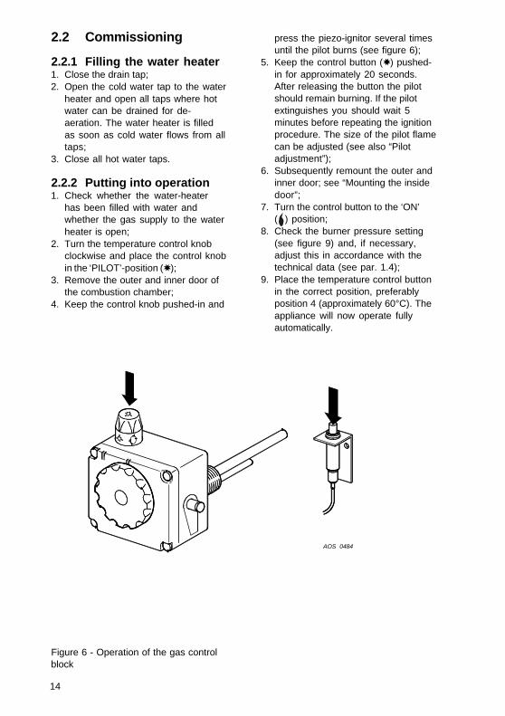
press the piezo-ignitor several timesuntil the pilot burns (see figure 6);
5. Keep the control button (✸) pushed-in for approximately 20 seconds.After releasing the button the pilotshould remain burning. If the pilotextinguishes you should wait 5minutes before repeating the ignitionprocedure. The size of the pilot flamecan be adjusted (see also “Pilotadjustment”);
6. Subsequently remount the outer andinner door; see “Mounting the insidedoor”;
7. Turn the control button to the ‘ON’( ) position;
8. Check the burner pressure setting(see figure 9) and, if necessary,adjust this in accordance with thetechnical data (see par. 1.4);
9. Place the temperature control buttonin the correct position, preferablyposition 4 (approximately 60°C). Theappliance will now operate fullyautomatically.
Figure 6 - Operation of the gas controlblock
AOS 0484

15
2.2.3 Removing and replacingthe inner door
(only for the BRV 30 NORS and BRV 40NORS model, see figure 7a).Mode of operation:1. Place lip A through the recess on the
right and subsequently slide it downbehind the steel wall. See to it thatboth lower lips remain in front of themetal wall;
2. Press lip B through the recess onthe left;
3. Subsequently slide lip B behind thesteel wall (see drawing 7a).
(only for the BRV 50 NRRT model, seefigure 7b).Procedure:1. Turn down both clamps (1).2. Place the entire door into the
appliance and move the openingover the burner venturi.
3. Turn both clamps outward (3),pushing them over the edge of theburner chamber.
2.3 Pilot adjustment
The pilot can be adjusted by means ofthe regulating screw under the plasticcover on the right hand side of the gascontrol block.Turn the screw clockwise to reduce thegas pressure and anti clockwise toincrease the pressure. Care should betaken to ensure the pilot covers thethermocouple element correctly.
2.4 Putting out ofoperation
1. For short periods of time the controlknob should be turned to (✸); thepilot keeps burning.
2. For longer periods of time the knobshould be turned to the (●) position;the pilot is extinguished.
Figure 7a - Removing and replacing theinner door
Figure 7b - Mounting the inside door
IMD 0359
IMD 0520
3
11
3

16
3. Close the gas tap in the supply pipe.In case of longer interruptions or inthe event of risk of frost it isrecommended to also close the coldwater tap and to drain the applianceafter cooling (open the drain tap; it ispossible to connect a drain hose tothe drain tap; open the nearest hotwater drain point to prevent airlocks).
To be able to drain the appliancecompletely it should be disconnectedand tilted slightly in the direction ofthe drain tap.
2.5 Temperature regulation
The appliance is under water supplypressure (maximum 8 bar). The amountof cold water that is added is equal tothe amount of hot water used. The gascontrol block automatically
regulates the gas supply. The mainburner will ignite as soon as a reductionin water temperature is sensed by thethermostat. The main burner will shutdown as soon as the presettemperature is achieved.
Position 1 = approximately 30°CPosition 2 = approximately 40°CPosition 3 = approximately 50°CPosition 4 = approximately 60°CPosition 5 = approximately 70°C
At high water temperatures there ismore scale buildup in the appliance. It isfor this reason that it is recommended toplace the temperature control knob inposition 4 as the accumulation of scalewill be reduced. In addition a safetythermostat has been fitted. Thisthermostat completely shuts off the gassupply if the water temperaturereaches 82°C, also extinguishing thepilot burner.
Figure 8 - Setting the pilot
IMD 0485
17
2.6 Setting the nominalheat input
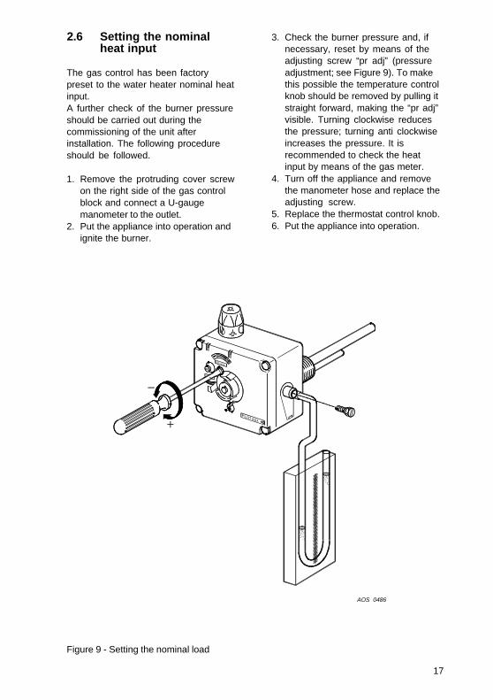
The gas control has been factorypreset to the water heater nominal heatinput.A further check of the burner pressureshould be carried out during thecommissioning of the unit afterinstallation. The following procedureshould be followed.
1. Remove the protruding cover screwon the right side of the gas controlblock and connect a U-gaugemanometer to the outlet.
2. Put the appliance into operation andignite the burner.
3. Check the burner pressure and, ifnecessary, reset by means of theadjusting screw “pr adj” (pressureadjustment; see Figure 9). To makethis possible the temperature controlknob should be removed by pulling itstraight forward, making the “pr adj”visible. Turning clockwise reducesthe pressure; turning anti clockwiseincreases the pressure. It isrecommended to check the heatinput by means of the gas meter.
4. Turn off the appliance and removethe manometer hose and replace theadjusting screw.
5. Replace the thermostat control knob.6. Put the appliance into operation.
Figure 9 - Setting the nominal load
AOS 0486

18
BRV 30 NORS BRV 40 NORS BRV 50 NRRT
G20 G30 G31 G20 G30 G31 G20 G30 G31
Inletpressure mbar 20 30 37 20 30 37 20 30 37
Burner pressure mbar 12.5 30 37 12.5 30 37 10.5 30 37
Diameter main mm 2.35 1.40 1.40 2.60 1.50 1.50 3.50 1.95 1.95injectorDiameter pilot 2x 2x 2xinjector mm 0.27 0.22 0.22 0.27 0.22 0.22 0.27 0.22 0.22
Unit
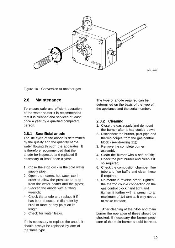
For conversion of the appliance fromnatural gas to another type of gas, orvice versa, it is necessary to exchangethe pilot injector and the main injector.The conversion may only be executedby a qualified competent person.
Procedure:1. Close the main gas tap in the gas
supply;2. Demount the burner (see
“Cleaning”);3. Replace the injector of the main
burner and the pilot burner with thecorrect injectors from theconversion set (see table above).
4a. Conversion from natural gasto LP-gas:- Put the pressure regulation of
the gas control block out ofoperation. To do this thetemperature regulating knobshould be pulled straightforward. Turn the ‘no pr’ (nopressure regulation) screwdown tight (see figure10);
- Seal this setting with lacquer;- Remount the burner in reverse
order;- Open the main gas tap.
4b. Conversion from LP-gas to naturalgas:- Put the pressure regulator into
operation. To do this thetemperature regulating knobshould be pulled straightforward. Next the red plasticcover that is now visible, shouldbe removed. Turn the ‘no pr’ (nopressure regulation) screwcompletely up (see figure 10);
- Seal this setting with lacquer;- Remount the burner in reverse
order;- Open the main gas tap;- Set the correct burner pressure
(see table above).5. If necessary adjust the pilot
correctly (see “Pilot adjustment”).6. Fit the correct sticker from the
conversion set on the appliance sothat it is clear that the appliancehas been converted and on whichgas the appliance operates.
2.7 Converting to anothertype of gas
Description
19
2.8 Maintenance
To ensure safe and efficient operationof the water heater it is recommendedthat it is cleaned and serviced at leastonce a year by a qualified competentperson.
2.8.1 Sacrificial anodeThe life cycle of the anode is determinedby the quality and the quantity of thewater flowing through the apparatus. Itis therefore recommended that theanode be inspected and replaced ifnecessary at least once a year.
1. Close the stop cock in the cold watersupply pipe;
2. Open the nearest hot water tap inorder to allow the pressure to dropfrom the water heater and the pipes;
3. Slacken the anode with a fittingwrench;
4. Check the anode and replace it if ithas been reduced in diameter by60% or more at any point on itslength;
5. Check for water leaks.
If it is necessary to replace the anode itshould always be replaced by one ofthe same type.
Figure 10 - Conversion to another gas
The type of anode required can bedetermined on the basis of the type ofthe appliance and the serial number.
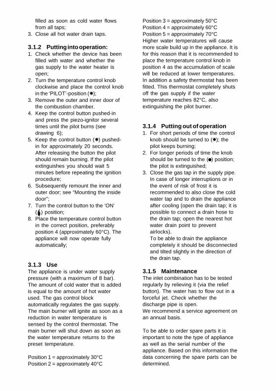
2.8.2 Cleaning1. Close the gas supply and demount
the burner after it has cooled down;2. Disconnect the burner, pilot pipe and
thermo couple from the gas controlblock (see drawing 11);
3. Remove the complete burnerassembly;
4. Clean the burner with a soft brush;5. Check the pilot burner and clean it if
so required;6. Check the combustion chamber, flue
tube and flue baffle and clean theseif required;
7. Re-mount in reverse order. Tightenthe thermo couple connection on thegas control block hand tight andtighten it further with a wrench to amaximum of 1/4 turn as it only needsto make contact;
After cleaning of the pilot- and mainburner the operation of these should bechecked. If necessary the burner pres-sure of the main burner should be reset.
AOS 0487

20
2.8.3 DecalcificationFormation of lime scale depends on thequality and quantity of the water used.In addition higher water temperatureslead to more deposit in the appliance. Atemperature setting of 60°C isrecommended in order to keep thecalcification at a low level.Decalcification should be attempted withthe proper means. For extensiveinformation a decalcification instructionis available.
2.8.4 Spare partsTo be able to order spare parts it isimportant to note the type of applianceas well as the serial number of theappliance. Based on this information thedata concerning the spare parts can bedetermined.
2.9 Inlet combination
Not applicable in U.K. and Ireland.
2.10 Fault finding
In case of failure the following shouldbe checked:
2.10.1 Safety thermostatAll appliances have been fitted with asafety thermostat that shuts off the gassupply when the water temperature istoo high. The safety thermostat remainsactivated until the water temperaturedrops below the safety temperature.The water heater must be reignitedmanually. The regulation thermostat
Figure 11- Mounting burner-set
AOS 0488

21
should be set to a lower watertemperature. If the pilot is extinguishedrepeatedly at higher temperatures thannormal, this indicates that the safetythermostat is operating.
2.10.2 Flue down draught safetydevice
If the flue tube safety device hasswitched off the appliance, theappliance can be put back into operationthrough the normal procedure. If the fluetube safety device repeatedly puts theappliance out of operation then thispoints to problems with the flue. Theonly remedy is to determine the causeof the problem (for instance a blockedchimney) and to solve the problem.
2.10.3 Hot water temperature toolow
1. Check the setting of the temperaturecontrol knob;
2. Check whether the pilot is alight. Ifnecessary ignite (see “Putting intooperation”);
3. Check whether there are any leaksor open taps;
4. Is the gas supply adequate? Checkand correct if necessary;
5. Perhaps the hot water consumptionis higher than was originallycalculated;
6. Check whether the cold water inlethas been correctly connected;
7. Check the thermostat sensor forscale build up.
2.10.4 Hot water temperature toohigh
Check whether the control thermostat isset too high.
2.10.5 Possible water leakage1. Check whether the drain tap is fully
closed;2. Check whether all water
connections are water tight;3. Check whether the possible water
leakage could be caused bycondensation.
2.11 Gas smell
WarningImmediately shut the main gas tap. Donot light any fire or switch on any lights,do not use any electrical switches oralarm bells. Open windows. Thoroughlyinspect all gas connections and, if thegas smell persists, alert the local gascompany and/or your installer.
2.12 Condensation
If the appliance is filled with coldwater or if the hot water consumption isvery high, condensation of flue gasseswill occur on the cold surfaces of thecombustion chamber and the flue tube.The water drops will fall on the burnerand cause a sizzling noise. This is anormal phenomenon that will disappearas soon as the appliance reaches itsnormal operating temperature.
IMPORTANT WARNINGThe applicance should NEVER betaken into operation with a closedcold water supply!Provision should always be madefor expansion.
3. FOR THE USER
3.1 Commissioning
WarningInstalling and commissioning (for thefirst time) of this water heater shouldonly be carried out by a qualifiedcompetent heating engineer.
3.1.1 Filling the water heater:1. Close the drain valve;2. Open the cold water valve to the
water heater and open all tapswhere hot water can be drained forde-aeration. The water heater is
filled as soon as cold water flowsfrom all taps;
3. Close all hot water drain taps.
3.1.2 Putting into operation:1. Check whether the device has been
filled with water and whether thegas supply to the water heater isopen;
2. Turn the temperature control knobclockwise and place the control knobin the ‘PILOT’-position (✸);
3. Remove the outer and inner door ofthe combustion chamber.
4. Keep the control button pushed-inand press the piezo-ignitor severaltimes until the pilot burns (seedrawing 6);
5. Keep the control button (✸) pushed-in for approximately 20 seconds.After releasing the button the pilotshould remain burning. If the pilotextinguishes you should wait 5minutes before repeating the ignitionprocedure;
6. Subsequently remount the inner andouter door; see “Mounting the insidedoor”;
7. Turn the control button to the ‘ON’( ) position;
8. Place the temperature control buttonin the correct position, preferablyposition 4 (approximately 60°C). Theappliance will now operate fullyautomatically;
3.1.3 UseThe appliance is under water supplypressure (with a maximum of 8 bar).The amount of cold water that is addedis equal to the amount of hot waterused. The gas control blockautomatically regulates the gas supply.The main burner will ignite as soon as areduction in water temperature issensed by the control thermostat. Themain burner will shut down as soon asthe water temperature returns to thepreset temperature.
Position 1 = approximately 30°CPosition 2 = approximately 40°C
Position 3 = approximately 50°CPosition 4 = approximately 60°CPosition 5 = approximately 70°CHigher water temperatures will causemore scale build up in the appliance. It isfor this reason that it is recommended toplace the temperature control knob inposition 4 as the accumulation of scalewill be reduced at lower temperatures.In addition a safety thermostat has beenfitted. This thermostat completely shutsoff the gas supply if the watertemperature reaches 82°C, alsoextinguishing the pilot burner.
3.1.4 Putting out of operation1. For short periods of time the control
knob should be turned to (✸); thepilot keeps burning;
2. For longer periods of time the knobshould be turned to the (●) position;the pilot is extinguished;
3. Close the gas tap in the supply pipe.In case of longer interruptions or inthe event of risk of frost it isrecommended to also close the coldwater tap and to drain the applianceafter cooling (open the drain tap; it ispossible to connect a drain hose tothe drain tap; open the nearest hotwater drain point to preventairlocks).To be able to drain the appliancecompletely it should be disconnectedand tilted slightly in the direction ofthe drain tap.
3.1.5 MaintenanceThe inlet combination has to be testedregularly by relieving it (via the reliefbutton). The water has to flow out in aforceful jet. Check whether thedischarge pipe is open.We recommend a service agreement onan annual basis.
To be able to order spare parts it isimportant to note the type of applianceas well as the serial number of theappliance. Based on this information thedata concerning the spare parts can bedetermined.
Fault Possible cause Corrective action
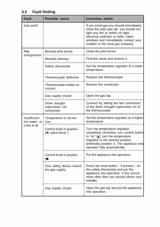
3.2 Fault finding
Blocked pilot burner
Blocked chimney
Safety thermostat
Thermocouple defective
Thermocouple makes nocontact
Gas supply closed
Down draughtsupervision notconnected.
Temperature is set toolow
Control knob in position(✸) (pilot burns )
Control knob in position(l)
Flue safety device closedthe gas supply
Gas supply closed
Gas smell
Pilotextinguishes
Insufficienthot water, ornone at all
If you smell gas you should immediatelyclose the main gas tap you should notlight any fire or switch on light,electrical switches or bells. Openwindows and immediately contact yourinstaller or the local gas company.
Clean the pilot burner
Find the cause and remove it.
Set the temperature regulator at a lowertemperature.
Replace the thermocouple
Restore the connection
Open the gas tap
Connect by sliding the two connectorsof the down draught supervision on tothe thermocouple.
Set the temperature regulator at a highertemperature
Turn the temperature regulatorcompletely clockwise; turn control buttonto “on” ( ); turn the temperatureregulator to the desired position,preferably position 4. The appliance nowoperates fully automatically.
Put the appliance into operation.
Press the reset button - if present - onthe safety thermostat and put theappliance into operation. If this occursmore often then you should inform yourinstaller.
Open the gas tap and put the applianceinto operation.

Fault Possible cause Corrective action
Insufficienthot water, ornone at all
Waterleakage
Set the temperature regulator at alower temperature and reignite thepilot burner.
Reduce the consumption of hot water.Allow the appliance time to heat thewater.
Turn the control button to the (l)position. Close the gas tap and informyour installer.
See “Condensation”.
Tighten the threaded connections.
Trace the cause.
Reduce your hot water use. Allow theappliance enough time to warm upwater.
Safety thermostat hasclosed the gas supplybecause the watertemperature was too high
Hot water storage empty
Cause cannot bedetermined
Condensation of (flue)gasses
Insufficient sealing of thewater connections(thread)
Leakage from otherwater- appliances orpipes near by
Condensation leakagefrom the underside of theappliance (usually duringthe first warming-upperiod).

4. WARRANTY
The following conditions form thequarantee agreement between BSSGROUP PLC (the warrantor) and theowner of the water heater.
4.1 Warranty in generalIf within one year of the originalinstallation date of the water heater anypart or component other than the tankshall prove upon examination by thewarrantor or authorised agent to bedefective in material or workmanship,the warrantor will exchange such partor component.
4.2 Warranty of the tankIf within 5 years of the originalinstallation date, the tank fails due torust or corrosion from the water side,the warrantor will supply a completenew water heater of equivalent sizeand duty (excluding delivery andinstallation charges). On thereplacement water heater a quaranteewill be granted sufficient to cover theunexpired portion of the original 5 yearswarranty of the originally installedwater heater.
4.3 Conditions for installationand use
The quarantee applies to the heater onlywhile it remains in its orignial location,and is installed in accordance with localplumbing and building regulations and allrelevant Codes of Practice.
The water heater should also havebeen used only:a) for potable water free to circulate at
all times and with the tank free ofdamaging scale deposits;
b) at temperatures not exceeding themaximum setting of its thermostatand ECO (Energy Cut Off device);
c) at water pressures and/or energyinputs which do not exceed thosestated on the rating plate of thewater heater;
d) in a non corrosive atmosphere orarea;
e) with an approved temperature andpressure relief valve of adequatecapacity not exceeding the workingpressure rating shown on the waterheater, and installed in conformitywith BSS GROUP PLC installationinstructions;
f ) when anode(s) have been inspectedand renewed, if they are worn orerroded by 50% of more at any pointof their length.
4.4 ExclusionsThe quarantee will be null and void:
a) if the water heater has beendamaged by an external cause;
b) in case of misuse, neglect (includingfrost damage) or incorrect use of thewater heater;
c ) in case of unauthorised alteration,modification or repair;
d) in case of ingress into the waterheater of chemicals, pollutants orcontaminants;
e) if the hardness of the incomingwater is, or has been, softenedbelow 106 ppm CaCO3 ;
f ) if the water heater is effected bycorrosive vapours such as thosefound in hairdressers, dry cleanersand laundries or where someindustrial degreasing products areused and stored (for furtherinformation and advise pleasecontact the BSS GROUP PLCTechnical Department).
4.5 Range of warrantyAll replacement water heaters suppliedunder the terms of this warranty will besupplied ex stock on an F.O.B. basis.BSS GROUP PLC accepts noresponsability for carriage, labour orother installation costs.
4.6 ClaimsAny claim under this warranty shouldbe initiated with the dealer whooriginally sold the water heater or withany other dealer or stockist of thewarrantors products.
25

4.7 No other guarantee orwarranty either expressedor implied is made onbehalf of BSS GROUP PLC.
With respect to the water heater inquestion further BSS GROUP PLC doesnot guarantee this water heater assuitable for purpose except within theterms of warranty detailed above.
BSS GROUP PLC will not be liable byvirtue of this guarantee or otherwise fordamage to any persons or propertywhen arising out of contracts or tort.
The terms of this guarantee do noteffect your statutory rights under UnitedKingdom Consumer Legislation.
This warranty applies to the followingmodels:BRV 30 NORS GBRV 40 NORS GBRV 50 NRRT G
26
MODEL: .........................................................................................................................
SERIAL NUMBER: .........................................................................................................
ORIGINAL DATE OF INSTALLATION: ............................................................................
NAME OWNER: .............................................................................................................
ADDRESS: ....................................................................................................................
TOWN: ..........................................................................................................................
(STAMP) INSTALLER: ...................................................................................................
ImportantThis form should be filled in completelywithin two weeks of installation.
27

0307 631 R0
28