Installation and Servicing Instructions - A.C.Wilgar RG3.pdf · Baxi Bermuda RG 3 Fireside Gas...
36
Baxi Bermuda RG 3 Fireside Gas Central Heating Unit Installation and Servicing Instructions Please leave these instructions with the user
-
Upload
truongthien -
Category
Documents
-
view
217 -
download
3
Transcript of Installation and Servicing Instructions - A.C.Wilgar RG3.pdf · Baxi Bermuda RG 3 Fireside Gas...

Baxi Bermuda RG 3Fireside Gas Central Heating Unit
Installation and Servicing Instructions
Please leave these instructions with the user

2
Baxi is one of the leading manufacturers of domestic
heating products in the UK.
Our first priority is to give a high quality service to our
customers. Quality is built into every Baxi product -
products which fulfil the demands and needs of
customers, offering choice, efficiency and reliability.
To keep ahead of changing trends, we have made a
commitment to develop new ideas using the
latest technology - with the aim of continuing to
make the products that customers want to buy.
Everyone who works at Baxi has a commitment to
quality because we know that satisfied customers
mean continued success.
We hope you get a satisfactory service from Baxi. If
not, please let us know.
Natural Gas
Baxi Bermuda RG3G.C.No 37 077 64
For use with the following boilers:Bermuda 45/4 MG.C.No 44 077 71Bermuda 45/4 EG.C.No 44 077 73Bermuda 57/4 MG.C.No 44 077 72Bermuda 57/4 EG.C.No 44 077 74Bermuda 51/5G.C.No 44 075 06
Baxi is a BS-EN ISO 9001Accredited Company
For use in GB / IE only.
Renewal
Baxi Bermuda RG3 RenewalG.C. No 37 075 06A
For use with the following boilers:Bermuda 401G.C.No 44 077 49Bermuda 552G.C.No 44 077 50Bermuda 45/3 MG.C.No 44 077 61Bermuda 45/3 EG.C.No 44 077 60Bermuda 57/3 MG.C.No 44 077 63Bermuda 57/3 EG.C.No 44 077 62Bermuda 45/4 MG.C.No 44 077 71Bermuda 45/4 EG.C.No 44 077 73Bermuda 57/4 MG.C.No 44 077 72Bermuda 57/4 EG.C.No 44 077 74Bermuda 51/5G.C.No 44 075 06

CONTENTS
PAGE 5
PAGE 6
PAGE 7
Fireplace OpeningHearth MountingWall Fixing
PAGE 8-15
Initial PreparationElectrical ConnectionsGas SupplyFitting the Fire
PAGE 16-18
Spillage Detection
PAGE 19
PAGE 20-23
Cleaning the Burner and InjectorsCleaning the Pilot Assembly
PAGE 24-30
Initial PreparationLight BulbsGlass Frame AssemblyRope SealCoal BedBurner and InjectorsPilot AssemblyElectro-Magnetic UnitLight Switch and Micro-switchGas Control Tap and Pilot FilterElectrode Lead, Resistor and Spark Generator
PAGE 31
PAGE 32-33
PAGE 34-35
IntroductionTechnical DataSite Requirements
Installation
Commissioning the Fire
Fitting the Outer Case
Annual Servicing
Changing Components
Short Parts ListFault FindingRenewal
3

4
IMPORTANT - Installation, Commissioning,Service & Repair
This appliance must be installed in accordance withthe manufacturer’s instructions and the regulationsin force. Read the instructions fully before installingor using the appliance.
In GB, this must be carried out by a competentperson as stated in the Gas Safety (Installation &Use) Regulations.
Definition of competence: A person who works for aCORGI registered company and holding currentcertificates in the relevant ACS modules, or validACoP equivalents, is deemed competent.
In IE, this must be carried out by a competentperson as stated in I.S. 813 “Domestic GasInstallations”.
Codes of Practice, most recent versionshould be used
Safe Installation
The appliance is suitable only for installation in GB and IEand should be installed in accordance with the rules in force.
In GB, the installation must be carried out by a CORGIRegistered Installer. It must be carried out in accordance withthe relevant requirements of the:• Gas Safety (Installation & Use) Regulations.• The appropriate Building Regulations either The BuildingRegulations, The Building Regulations (Scotland), BuildingRegulations (Northern Ireland).• The Water Fittings Regulations or Water Byelaws inScotland.• The Current I.E.E. Wiring Regulations.
Where no specific instructions are given, reference should bemade to the relevant British Standard Code of Practice.
In IE, the installation must be carried out by a competentPerson and installed in accordance with the current edition ofI.S. 813 ‘Domestic Gas Installations’, the current BuildingRegulations and reference should be made to the currentETCI rules for electrical installation.
These Instructions must be read in conjunction with those forthe Boiler Section before installing or using this appliance.
Information
In GB the following Codes of Practice apply:Standard ScopeBS 6891 Gas Installation.BS 5546 Installation of hot water supplies for
domestic purposes.BS 5871 Installation of gas fires, convectors and
fire/back boilers.BS 5440 Part 1 Flues.BS 5440 Part 2 Ventilation.BS 6798 Installation of gas fired hot water boilers.BS 5449 Part 1 Forced circulation hot water systems.
In IE the following Codes of Practice apply:Standard ScopeI.S. 813 Domestic Gas Installations.The following BS standards give valuable additional information;BS 5546 Installation of hot water supplies for
domestic purposes.BS 5449 Part 1 Forced circulation hot water systems.
IMPORTANT - The addition of anything that mayinterfere with the normal operation of theappliance without express written permissionfrom the manufacturer or his agent couldinvalidate the appliance warranty. In GB thiscould also infringe the GAS SAFETY (Installationand Use) REGULATIONS.

INTRODUCTION
Baxi Bermuda RG3G.C.No 37 077 64
Description
The Baxi Bermuda RG3 (G.C. No 37 077 64) is acombined gas fired central heating boiler and gas fireunit, designed for installation in a living room. The boilerand fire unit is designed to be used on Natural Gas only.
The heat input of the fire at maximum setting is 5.52kW(18,834 Btu/h) with an output of 3.47kW (11,865 Btu/h).
The fire is controlled by a knob which is positioned onthe right hand side of the case. This knob has sixpositions giving a choice of four output settings.
Position - OFFPosition - IGNITION/PILOTPosition 1 - LOWPosition 2 - MEDIUMPosition 3 - MEDIUM/HIGHPosition 4 - HIGH
When required, the artificial coal bed may be illuminatedby concealed bulbs. The light effect is operated by aswitch situated below the control knob. It may be usedwhether the fire is ON or OFF.
Important InformationThis product contains Refractory Ceramic Fibres(R.C.F.) which are man-made vitreous silicate fibres.Excessive exposure to these materials may causetemporary irritation to eyes, skin and respiratory tract.Care must be taken when handling these articles toensure the release of dust or fibres is kept to aminimum.To ensure that the release of fibres from these articlesis kept to a minimum, during installation and servicing itis recommended that a H.E.P.A. filtered vacuum is usedto remove any dust, soot or other debris accumulated inand around the appliance. This should be performedbefore and after working on the installation.It is recommended that any replaced item(s) are notbroken up but sealed within heavy duty polythene bagsand clearly labelled “R.C.F. waste”. This is not classifiedas “hazardous waste” and may be disposed of at atipping site licensed for the disposal of industrial waste.Protective clothing is not required when handling thesearticles but it is recommended that gloves are worn andthe normal hygiene rules of not smoking, eating ordrinking in the work area are followed and always washhands before eating or drinking.NOTICE
DISCOLOURATION OF WALL SURFACES
Most heating appliances generate warm air convectioncurrents and transfer heat to any wall surface against whichthey are situated.
Some soft furnishings (such as blown vinyl wallpapers) maynot be suitable for use where they are subject to temperaturesabove normal room levels and the manufacturer's adviceshould be sought before using this type of wall coveringadjacent to any heating appliance.
The likelihood of wall staining from convected air currents willbe increased in environments where high levels of cigarettesmoke or other contaminants exist.
5

Bermuda RG3 (Natural Gas)
Heat Input (Gross) High Med-High
kW 5.52 4.88
Btu/h 18,834 16,637
Heat Input (Gross) Med Low
kW 3.72 2.00
Btu/h 12,693 6,824
Setting Pressure Cold
mbar 8.8 + 0.5
in wg 3.52 + 0.2
Gas Connection The gas supply is provided from the service cock on the boiler unit.
Electricity Supply230V~50HzExternal fuse - 3AmpAppliance Rating - 30 watt
Controls Rotary gas tap with flame sensing device, electronic ignition and A.S.D. pilot.
Weight 37.7 kg (82.9 lbs)(unpacked)
Thermocouple 9.4 - 13mvOutput
Gas Rate 0.60m3/h(after 10 mins) (21.20ft3/h)
Outercase Height 733mmDimensions
Width 765mm
Depth 305mm
Heat Output High
kW 3.47
Btu/h 11,865
76mm
100mm
Clearances
TECHNICAL DATA
6
Injectors
Front F06
Rear F02Pilot Assembly 9027
Heat Input (Gross) 210W (715 Btu/h)

SITE REQUIREMENTS
305mm
13mm800mm
Fireplace OpeningThe principal site requirements are determined by theboiler unit, but the following details are essential forthe correct installation of the fire unit:
Fireplace Opening: Height: 560mm (22in)Width: 406mm (16in) min
584mm (23in) max
NOTE: The wall behind the fire must be non-combustible.
If a fire surround is to be used, it must have a rating of100o C or higher (Any gaps between the wall and the
surround must be sealed).
There must be a flat vertical surface, centrallyfixed about the opening, measuring a minimumof 810mm (317/8 in) high by 800mm (311/2 in)wide.
VENTILATIONVentilation air supply should be in accordancewith the relevant standards. In GB this is BS5440 Pt. 2. In IE this is I.S. 813 “Domestic Gas
Installations”. The permanent ventilation areasize requirements are:-
RG3 & 45/4 69.71cm2 (10.8in2)RG3 & 57/4 90.32cm2 (14in2)RG3 & 51/5 74.63cm2 (11.57in2)
The permanent vent may be directly into the roomcontaining the appliance. The vent may also be sitedin another room provided an interconnecting vent isused. The vent must not be installed inside thebuilders opening. The vent should be sited followinggood practice for a habitable room.We recommend the use of the Stadium BM720 ‘BlackHole’ ventilator which is available from your localmerchant.
HEARTH MOUNTINGIf the fire unit is to be hearth mounted then the hearthmust be of a non-combustible material at least 13mm(1/2in) thick and measuring at least 305mm (12 in) deepby 800mm (311/2 in) wide and fitted centrally about thefireplace opening. The top surface of the hearth shouldbe a minimum of 50mm (2in) above floor level andmust be level with the base of the builders opening.On no account should the fire unit be fitted directlyonto a combustible floor or carpet.
WALL FIXINGNOTE: Whilst the Bermuda RG3 is
intended to be hearth mounted, it mayalso be fixed to a wall.
The bottom of the fire unit must be atleast 100mm away from the
floor, but not more than125mm.
SHELFA shelf may be fittedabove the fire unit
provided that it is at least76mm (3in) above the fire
canopy and not more than229mm (9in) in depth. The area between the
shelf and the top of the fire must be non-combustible.
50mm
406mm Min584mm Max
560mm
810mm
800mm
125mm Max100mm Min
FireplaceOpening
229mm
76mm
7

Initial Preparation
Unpack the fire unit.
Electrical Connections
THIS APPLIANCE MUST BE EARTHED
NOTE: The method of connection to the electricitysupply must facilitate complete electrical isolationof the combined appliance (Fire and Boiler).
Connection may be made via a fused double poleisolator switch with a contact separation of at least3mm (1/8 in) in all poles. The switch should befused at a maximum of 3 amp and must serve theboiler or system controls only. Alternatively, theconnection should be made via a standard 3-pinplug, fused at a maximum of 3 amp.
Any 4-core cable used for connection to the boilerunit must NOT be less than 0.75mm2 (24 x 0.2mm)PVC IEC 53 code 227 (heat resistant).
Electricity is supplied to the fire via the boiler unit.
The electrical connection between the fire andboiler unit is made by wiring the socket and cable
assembly, that is supplied with the fire unit, into thesocket on the boiler. Ideally, this connection should
be made at the same time as the electricalconnections to the boiler unit.
b
b
N
E
Lbr
r
w
Micro-Switch
Resistor
KEYbr - Brownb - Bluew - Whiter - Redg/y - Green & Yellow
BulbsLightSwitch
Spark Generator
Spark Generator
Functional Flow Diagram
Electrode
INSTALLATION
w
b
w
b
b
b br
r
b brg/y
g/y
Electrode
Plug
Micro-Switch
Light Switch
Terminal Strip
Resistor
BulbBulb
LAMP BOX
Pilot / A.S.D.Assembly
8

Manual Control Models
If the fire supply cable has not been fitted when wiringthe boiler proceed as follows:-
CONNECTING ELECTRICAL SUPPLY TOTHE BOILER
Connect the wiring to the boiler asfollows:-
Extract the screw that fixes the boilercontrols connection plug to the socket
on the boiler base tray and disconnectthe plug. Retain the screw.
Extract the screw that fixes the socket to the boilerbase tray and remove the socket by sliding it to theright. Retain the screw.
Extract the screw that fixes the cover to thesocket housing and remove the cover to
reveal the terminals and cable clamps.Retain the screw.
The switched live must be connectedto the terminal marked "L1".
The permanent live must be connectedto one of the terminals marked "L2".
The neutral must be connected to one of theterminals marked "N".
Route the green and yellow wire (EARTH) through thecut-out in the socket housing and connect it to theearth terminal on the boiler base tray.
NOTE:- The earth wire should be sufficiently long,so that if the supply cable is pulled on, the liveand neutral wires will become taut before the earthwire.
Secure the cable in the socket with the cable clamp.For 3-core cable use the flat side of the cable clampdownwards and for 4-core cable use with the radiusside of the cable clamp downwards.
9
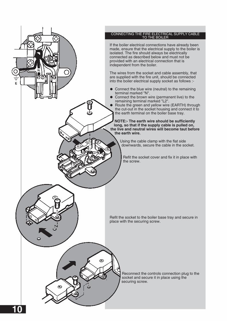
CONNECTING THE FIRE ELECTRICAL SUPPLY CABLETO THE BOILER
If the boiler electrical connections have already beenmade, ensure that the electrical supply to the boiler isisolated. The fire should always be electricallyconnected as described below and must not beprovided with an electrical connection that isindependent from the boiler.
The wires from the socket and cable assembly, thatare supplied with the fire unit, should be connectedinto the boiler electrical supply socket as follows :-
Connect the blue wire (neutral) to the remaining terminal marked "N". Connect the brown wire (permanent live) to the remaining terminal marked "L2". Route the green and yellow wire (EARTH) throughthe cut-out in the socket housing and connect it to the earth terminal on the boiler base tray.
NOTE:- The earth wire should be sufficientlylong, so that if the supply cable is pulled on,
the live and neutral wires will become taut beforethe earth wire.
Using the cable clamp with the flat sidedownwards, secure the cable in the socket.
Refit the socket cover and fix it in place withthe screw.
Refit the socket to the boiler base tray and secure inplace with the securing screw.
Reconnect the controls connection plug to thesocket and secure it in place using thesecuring screw.
10

Electronic Controls ModelsIf the boiler electrical connections have
already been made, ensure that theelectrical supply to the boiler isisolated. The fire should alwaysbe electrically connected as
described below and must notbe provided with an electricalconnection that is independentfrom the boiler.
Remove the controls heat shieldfrom its retaining clips.
Remove the electrical inlet socketfrom the PCB at the rear left handside of the control box.
Remove the socket cover. The socket should be wiredas described in the boiler Installation and ServicingInstructions.
If the firefront being installed isequipped with either lighting
effects or lighting effects andelectronic ignition the plugmust be wired as shown:
Connect the controlswitched live to L.
Connect neutral to N.
Connect earth to .
The live of the fire supplycable must also be connected
to the terminal block.
Neutral and Earth of the fire supply cable can then beconnected to N and respectively.
If the firefront does not require a permanent live feed,wire the plug as shown. The loose terminal block canbe discarded.
Refit the cable clamp ensuring that the outerinsulation is securely held and refit the socket cover.
Ensure that all cables are routed away from theboiler casing and hood.
Controls HeatShield
11
SL L N
SL L N
SL L N
Loop
LooseTerminalBlock
Cut the end of theearth tag from thefire supply cableearth wire.
FromFirefrontFrom Control
System &Permanent Live

12
Electronic Controls Model (51/5 only)
Remove the controls heat shield from its retainingclips.
Isolate the electrical supply to the boiler, including thepermanent live.
Remove the electrical inlet socket from the PCB at therear left hand side of the control box.
Remove the socket cover. The socket should be wiredas described in the boiler Installation and ServicingInstructions. The boiler plug is supplied as shown : Anearth lead connects to the boiler chassis.
If the firefront being installed is equipped with eitherlighting effects or lighting effects and electronicignition the plug must be wired as shown:
Connect the control switched live to SL.
Connect neutral to N.
Connect earth to .
Connect the permanent live to L.
The fire earth must connect to the chassis.
Neutral and Live of the fire supply cable can then beconnected to N and L respectively.
If the firefront does not require a permanent live feed,wire the plug as shown. The loose terminal block canbe discarded.
Refit the cable clamp ensuring that the outerinsulation is securely held and refit the socket cover.
Ensure that all cables are routed away from theboiler casing and hood.
4 Pin ElectricalInlet Socket
3 Pin ElectricalPlug
SL L N
From Control System& Permanent Live
SL L N
FromFirefront
SL L N

Gas Supply
The gas installation should be in accordance with relevant standards. In GB this is BS 6891. In IE this isI.S. 813 “ Domestic Gas Installations”.
The gas supply to the fire unit is provided from theservice cock on the boiler using the fire supplypipe contained in the kit.
The pipe has one flared end (for connection tothe fire) and a plain end (for connection to theservice cock).
It will be necessary to cut the fire supply pipe tolength. The length will depend on the position ofthe boiler unit relative to the face of the wall orsurround.
The following procedure will ensure that thepipe is cut to the correct length.
Measure the distance from the centre of the front‘V’ mark on the boiler base tray to the face of the wallor surround. Let this distance be known as distance‘A’.
Add 35mm to distance 'A', (ie: A + 35mm) to give atotal distance 'D'.
Mark off distance ‘D’ from the plain end of thesupply pipe.
Cut away the unwanted piece of pipe, ensuring thatthe cut is square.
Remove burrs and clear the pipe of any swarf.
Two compression nuts and an olive are provided inthe kit. Thread one nut over the fire supply pipe, asshown, then fix the plain end of the pipe to the servicecock on the boiler using the olive and remaining nut.Ensure that the flared end of the pipe faces to theright and is parallel with the hearth or floor before fullytightening the nut and olive.
Surround Face orFinished Wall Face
Front "V" Mark
Gas Service Cock
13
D

Fitting the Fire
HEARTH FIXING
Ensure that the space between the flue liner and thechimney has been sealed, as described in the fluessection of the Boiler Instruction.
The backing plate that will be used to secure the fireto the wall is already fastened to the fire in readinessfor marking out the screw fixing holes. It is located atthe top back position of the fire unit.
The following procedure is to be followed whenfitting the fire.
Locate the fire flue spigot into the boiler canopy andwhilst ensuring that the down-draught diverter on thefire unit passes over the controls heat shield, push thefire backwards until the backing plate touches thesurround or wall surface.
Level the fire by adjusting the front feet (check using aspirit level).
Mark the positions of two suitable fixing holes inthe backing plate. NOTE: Where possible the
top corner fixing hole positions should beused, otherwise space the fixing holes as far
apart as possible.
Withdraw the fire unit and remove thebacking plate from the chassis byunscrewing the two screws holding it inposition. Take note of its orientation andretain the screws.
Drill the fixing holes in the surround or wallface to accept the wall plugs provided.
Fix the backing plate onto the wall using thescrews provided.
Relocate the fire and push up against the backingplate. The fire is secured to the backing plate usingthe screws previously removed.
The lamp box, which is clipped at the top and hingedat the bottom is rotated forward to expose the boilercontrols. Use the handles provided.
Connect the supply pipe to the fire inlet connectionand tighten the flared joint.
Backing Plate
Down-DraughtDiverter
Fire FlueSpigot
Boiler Canopy
Controls HeatShield
Lamp Box
Handle
14
Supply Pipe

WALL FIXING
Ensure that the space between the flueliner and the chimney has been sealed,as described in the flues section of theBoiler Instruction. On electronic controlboilers it will be necessary to removethe inlet plug from the controls.
Take the fire support plate from the fireunit packaging and loosely attach it to the
boiler base protruding from the fireplaceopening using the screws provided. Use the
slots at each side.
Push the support plate backwards until it touches thesurround or wall face and tighten the screws to lock itin position.
Locate the fire flue spigot into the boiler canopy andwhilst ensuring that the down-draught diverter on thefire unit passes over the controls heat shield, push the
fire backwards until the backing plate touches thesurround or wall surface.
Level the fire by adjusting the front feet (checkusing a spirit level).
Mark the positions of twosuitable fixing holes in thebacking plate. NOTE: Wherepossible the top cornerfixing hole positionsshould be used, otherwisespace the fixing holes as
far apart as possible.
Withdraw the fire unit and removethe backing plate from the chassis by
unscrewing the two screws holding it inposition. Take note of its orientation and
retain the screws.
Drill the fixing holes in the surround or wallface to accept the wall plugs provided.
Fix the backing plate onto the wall using thescrews provided.
Relocate the fire and push up against thebacking plate. The fire is secured to the backing
plate using the screws previously removed.
The lamp box, which is clipped at the top and hingedat the bottom is rotated forward to expose the boilercontrols. Use the handles provided.
Connect the supply pipe to the fire inlet connectionand tighten the flared joint.
Backing Plate
Down-DraughtDiverter
Fire FlueSpigot
Boiler Canopy
Controls HeatShield
Lamp Box
Handle
Fire SupportPlate
15
Supply Pipe

Three clips across the top of the glass frame secure itin position. When the clips are released, the glassframe assembly will lean outwards to rest on itsbottom location positions, from which it can be liftedclear of the fire. The two outer clips should bereleased before the centre one. Release the clips bygripping centrally and pulling upwards.
Remove the packing piece that retains thecoalbed and lift the coalbed clear of itslocation pegs.
CAUTION:- The coalbed is extremelyfragile and must be handled
accordingly. Gloves should be wornand any inhalation of the dust should
be avoided. Keep the coals awayfrom children at all times.
Please read the ImportantInformation section on page 4.
Check that the spark gap betweenthe electrode and thermocouple is
between 2.5 and 4mm.
Take the coalbed out of its plastic bagand replace it in position on the burner.
Replace the glass frame assembly by lowering it intoits bottom locating positions and, whilst holdingagainst the rope seal, engage the retaining clips. To
engage the clips, locate the front of the clip over thetop edge of the glass frame and push the top of
the clip downwards. The centre clip should bereplaced before the outer clips.
Turn on the mains gas and electricitysupplies.
Turn the gas service cock to the fire and boiler ONposition by turning fully anti-clockwise, then purgeaccording to in GB BS 6891 and in IE the current
edition of I.S. 813 “Domestic Gas Installations”.
Check for gas soundness from the gas service cock tothe fire inlet position.
Connect the electricity supply to the fire byfixing the 3-pin socket that comes from theboiler into the plug provided on the fire unit.The plug is situated towards the left, in the
space behind the lamp box.
COMMISSIONING THE FIRE
Rotate Lamp BoxForward UsingThe Handles
Handle
Socket
2.5 to 4mm
Glass Frame
Boiler/Fire
View of Boiler Controls(Manual Model shown)when Lamp Box isrotated forward
16

Switch on the bulbs. If the bulbs light, thenswitch off and proceed. If they do not lightisolate the electricity supply and performpreliminary electrical system checks before
proceeding, ie earth continuity, polarity,resistance to earth etc.
Release the pressure test point sealing screw fromthe gas control tap and connect a pressure gauge inposition.
Push in the control knob, turn to theIgnition/Pilot position ( ) and hold in.Sparking will commence and the pilotwill light. The pilot is visible at the frontcentre of the coalbed.
Continue to hold the control knob in fora further 15 seconds, then release. The
sparking will stop and the pilot will remainalight.
The pilot has two flames, one to ignitethe main burner and one to operate theflame supervision device. Both flamesshould be approximately 20mm longwith a clean and stable appearance.
If the pilot does not remain alight, wait2 minutes and repeat the process. If the
pilot still fails to remain alight, refer to thefault finding chart.
Turn the control knob to position 4and check the setting pressure. Ifthis is not correct, check that allgas cocks are fully open and thatthe meter pressure is correct. Noadjustment to the setting pressure
is possible.
Turn the control knob to the OFF position ( ).Disconnect the pressure gauge and replace thepressure test point sealing screw, ensuring a gas tightseal.
4
17

CHECKING FOR SPILLAGE
CAUTION - Whilst checking for spillage care mustbe taken to avoid touching hot panels.
Ensure that all doors and windows are closed.
IMPORTANT NOTE: If there is a ceiling orextractor fan in the room or adjoining room thenthe spillage test must be performed with the fanturned on and any interconnecting doors betweenthe fan and the appliance left open.
There are two stages of appliance operation for whichspillage must be checked by following "the spillagechecking procedure" shown below.
STAGE 1 - Operate the fire on maximum for fiveminutes and check for spillage. If spillage is evidentthen the fire is operated for a further 10 minutes andre-checked. If spillage is still evident then the causeshould be ascertained and rectified before continuingwith commissioning.
STAGE 2 - Following a satisfactory result at stage 1,the fire is left on and the boiler is operated for 5minutes before checking for spillage again. If spillageis evident then the cause should be ascertained andrectified before continuing with commissioning.
If the appliance cannot be commissioned then itshould be isolated until the problem is resolved.
THE SPILLAGE CHECKING PROCEDURE
Checking for spillage is only possible from the lefthand side of the appliance. A lighted smoke matchwith extension is inserted into the boiler canopy andpositioned just below but not touching the fire fluespigot. With the aid of a torch the trail of smoke fromthe match is observed. If the smoke is not beingdrawn up into the flue then spillage of combustionproducts is indicated.
POSSIBLE CAUSES OF SPILLAGE
The smoke match may have been positionedincorrectly, resulting in the smoke being picked up byhot convected air currents.
The builders opening or flue installation may beunsound.
Inadequate ventilation.
Down draughts may be present.
The flue may be blocked.
SmokeMatch
SmokeMatch
Fire Flue Spigot
Boiler Canopy
Access for Spillage CheckingProcedure
18

FITTING THE OUTER CASE
First turn off the fire and allow it to cool down.
There are 3 outer case components which are tobe fitted as follows:-
FIRE TOP PANELHold the panel on either side with the screw fixingholes towards the front.
Angle the panel backwards and by guiding the centrelocating ledge at the rear of the panel, into the slotprovided on the fire, locate the panel onto the fire.
The front of the panel should now be brought downso that the screw fixing holes are forward of thecaptive nuts provided on the fire. Secure the panel
using the two 1/2 in self tapping screws provided.
FIRE FACIALocate the facia on the lip at the top of the
fire.
Secure the two fasteners at the bottomof the facia by pushing in and turningclockwise.
HEARTHGuide the hearth locating pins into theholes in the facia.
Push the bottom of the hearthinwards to ensure the clips on eitherside are engaged.
These instructions and the users instructionsshould be handed over to the customer. At the sametime the customer should be shown how to operatethe fire safely and efficiently.
The need for Annual Servicing should be pointed outand returning of the guarantee card advised.
Fire Top Panel
Fire Facia
Hearth
Locating Lip
Locating Lip
Centre Locating Ledgeat Rear of Top Panel
19

For reasons of safety and economy it is important toservice both the fire and boiler unit annually. Beforeservicing please read the Important Informationsection on page 5.
IMPORTANT: It is possible that some soot may bedeposited on the coals after use. This is acceptableproviding it is not allowed to accumulate.
CAUTION:- The coalbed is extremely fragile andmust be handled accordingly. Gloves should beworn and any inhalation of the dust should beavoided. Keep the coals away from children at alltimes.
PREPARATION
In order to service the boiler unit, the fire must bedisconnected and removed. Once disconnected, thefire unit may be serviced separate from the boiler.
WARNING:- ISOLATE THE GAS AND ELECTRICITY SUPPLIES,INCLUDING THE PERMANENT LIVE, TO THE BOILER AND FIREUNIT BEFORE SERVICING.
Remove the Outer Case Components asfollows :-
Ensure the fire is cold.
Remove the fire hearth by grasping it oneither side at the bottom and pullingtowards you. This will release the clips and
allow the hearth to be lifted away by drawingit forward.
Release the fasteners at thebottom of the facia panel byturning them anti-clockwise.
The facia panel which is supported on alip at the top of the fire can now beremoved. Grasp the facia on either side
and bring slightly forward before liftingclear of the lip.
ANNUAL SERVICING
Locating Lip
20

Remove the Fire chassis as follows :-
The lamp box, which is clipped at the top and hingedat the bottom is rotated forward to expose the boilercontrols. Use the handles provided.
Electricity is supplied to the fire by means of a 3pin socket from the boiler. The plug is situatedtowards the left in the space behind the lamp box.Disconnect the socket from the plug on the fire and
lay it on the boiler tray.
Turn off the gas service cock on the boiler by turningfully clockwise.
Disconnect the fire supply pipe from the fire inlet.
Clip the lamp box back into position.
If required, the top panel on the fire can be removed,to gain better access to the lifting points. To do this,
remove the two fixing screws securing it and lift thepanel up at the front.
Remove and retain the two screws fixing thefire chassis to the backing plate.
Pull the fire forwards until the fire fluespigot is clear of the boiler canopy andlift away.
Remove the Glass Frame andCoalbed as follows :-
The 3 clips that secure the glass frameassembly are now visible across the top
edge of the glass frame. The two outerclips should be released before the centre
one. Release the clips by gripping centrallyand pulling upwards.
When the clips are released, the glass frameassembly will lean outwards to rest on its bottom
location positions, from which it can belifted clear of the fire.
The coalbed is positioned on twolocating pins. Lift the coalbedvertically to clear the pins.
Rotate Lamp BoxForward UsingThe Handles
Fire SupplyPipe
Handle
Socket
Glass Frame
View of Boiler Controls(Manual Model shown)when Lamp Box isrotated forward
21

CLEANING THE BURNER/INJECTORS
Release the compression nuts that connect the gasfeed pipes to the injectors on the burner.
The coalbed location pins also secure the burner inposition. Unscrew and remove the pins.
Manoeuvre the burner clear of the fire, taking care notto damage the pilot assembly.
The injectors can now be removed from theburner. Using a soft brush, remove any dirt ordebris from the top of the burner and ensurethat the ports and aeration openings are free
from obstruction.
Examine and clean the injectors. Do notuse any hard tools, including pins or wire. Refit
the injectors to the burner.
NOTE:- The larger injector should be fitted into thefront burner inlet position.
Replace the burner in the reverse order of removal.
CLEANING THE PILOT/A.S.D. ASSEMBLY
NOTE:- No attempt should be made to clean thedevice using any hard tools, including pins orwire.
The thermocouple, electrode and pilot burner thatmake up the pilot assembly are not replaceable asseparate items. If any part is damaged then the
pilot assembly should be replaced.
During annual appliance servicing the pilotassembly should be inspected for damage to
any of the component parts and any lint ordebris should be carefully removed fromthe aeration hole.
Check that the spark gap between theelectrode and thermocouple is between 2.5
and 4mm.
Some appliances may experience nuisance shutdown of the pilot. A pilot shield kit (Baxi Part No.237319) is available to prevent this.
22
2.5 to 4mm

REPLACING THE FIRE
Once the boiler has been serviced, the fire can bereplaced.
Locate the fire flue spigot into the boiler canopy andwhilst ensuring that the down-draught diverter on
the fire unit passes over the boiler controls heatshield, push the fire back against the backingplate. The fire is secured to the backing plateusing the screws previously removed.
Re-connect the gas supply pipe to the fire inlet.
EXAMINATION AND ASSEMBLY OFCOMPONENT PARTS
Examine the coalbed for damage and ensure that theapertures are free from blockages. If any damage hasoccurred then a new coalbed should be fitted. Thecoalbed is re-fitted by lowering it onto the location pins.
Examine the glass frame sealing rope on the fire and ifany damage has occurred, fit a new one.
Examine the glass frame assembly and if it is in anyway damaged, then a new one must be fitted. Ifsatisfactory, the glass frame assembly should now befitted. Lower the glass frame assembly into its bottomlocation positions and push back onto the sealing rope.Engage the clips onto the front edge of the glass frameand push down to lock. The centre clip should besecured before the outer clips.
RECOMMISSIONING
After servicing the appliance it must berecommissioned by refering to the instructionscontained in the section “Commissioning the Fire”.
Down-DraughtDiverter
Fire FlueSpigot
Boiler Canopy
Controls HeatShield
Glass FrameSealing Rope
23
Supply Pipe

CAUTION :- After replacing any gas carryingcomponents always check for gas soundness. (BS 6891). Before changing any components
please read the Important Information section onpage 5.
INITIAL PREPARATIONRemove the Outer Case Components asfollows :-
Ensure the fire is cold.
Remove the fire hearth by grasping it oneither side at the bottom and pulling towardsyou. This will release the clips and allow the
hearth to be lifted away by drawing itforward.
Release the fasteners at thebottom of the facia panel, byturning them anti-clockwise.
The facia panel which is supported on alip at the top of the fire can now beremoved. Grasp the facia on either sideand bring slightly forward, before lifting
clear of the lip.
The outer case components are replaced by reversingtheir method of removal.
ISOLATE THE GAS AND ELECTRICITY SUPPLIESAS FOLLOWS :-
The lamp box, which is clipped at the top and hingedat the bottom, can now be rotated forward to allowaccess for isolating the gas and electrical supplies tothe fire. Use the handles provided.
Isolate the electrical supply to the fire by unpluggingthe 3 pin socket from the plug on the fire. The plugis situated towards the left in the space behind thelamp box.
Turn off the gas supply to thefire, at the gas service cock onthe boiler, by turning fully
clockwise.
CHANGING COMPONENTS
Locating Lip
Rotate Lamp BoxForward UsingThe Handles
Handle
Socket
View of Boiler Controls(Manual Model shown)when Lamp Box isrotated forward24

LIGHT BULBS
Your attention is drawn to the safety notice found onthe lamp box. With the electricity supply to the fireisolated, the light bulbs can be changed asnecessary. They should only be replaced with 15Watt pygmy bulbs.
GLASS FRAME ASSEMBLY
Ensure that the glass panel is cold.The 3 clips that secure the glass frame assembly are
now visible across the top edge of the glassframe. The two outer clips should be released
before the centre one. Release the clips bygripping centrally and pulling upwards.
When the clips are released, the glass frameassembly will lean outwards to rest on itsbottom location positions, from which it canbe lifted clear of the fire.
Fit the new glass frame assembly by loweringit into its bottom location positions and pushing
it back onto the sealing rope. Engage the clipsonto the front edge of the frame and push down to
lock. The centre clip should be secured before theouter clips.
ROPE SEAL
Remove the glass frame assembly.
Pull the rope seal out of its location channel anddiscard.
Fit the new rope seal into the location channel bylocating the centre of the rope seal into the centre ofthe top location channel and working around thechannel so that there is an equal length down eitherside.
Replace the glass frame assembly.
COAL BED
Remove the glass frame assembly.
The coalbed is positioned on two locating pins. Liftthe coalbed vertically to clear the pins.
CAUTION:- The coalbed is extremely fragile andmust be handled accordingly. Gloves should beworn and any inhalation of the dust should beavoided. Keep the coals away from children at alltimes.
Fit the new coalbed by lowering it onto the locationpins.
Replace the glass frame assembly.
Rope Seal
Glass Frame
25

BURNER AND INJECTORS
Remove the glass frame assemblyand coalbed.
Release the compression nuts thatconnect the gas feed pipes to the
injectors on the burner.
The coalbed location pins also secure the burner inposition. Unscrew and remove the pins.
Manoeuvre the burner clear of the fire, taking care notto damage the pilot assembly.
The injectors can now be removed from theburner.
Assemble the combination of new or old, burnerand injectors, that are to be replaced.
NOTE:- The larger injector should be fitted into thefront burner inlet position.
Replace the burner in the reverse order of removal.Replace the coalbed and glass frame assembly.
Glass Frame
26

PILOT ASSEMBLY
Remove the glass frame assembly andcoalbed.
Grip the pilot assembly and loosenthe compression nut that connects the
pilot gas supply pipe to it.
Remove the two screws that retain thepilot assembly.
Remove the pilot gassupply pipe andother associatedwires out of thelocation clip.
Release the pilot gassupply pipe from the
pilot by unfastening thecompression nut.
Disconnect the electrode lead fromthe electrode.
Remove the thermocouple lead from theend of the gas control tap by unscrewing thesmall retaining nut and draw the pilot assembly
out of the fire chassis.
Replace the pilot assembly in the reverse order ofremoval.
NOTE:- Care should be taken not to over tightenthe nut that secures the thermocouple lead intothe end of the gas tap.
Replace the coalbed and glass frame assembly.
ELECTRO-MAGNETIC UNIT
IMPORTANT:- If the appliance is fitted with a pilotshield, electro-magnetic unit part no.239413should be ordered. Appliances without a shield require partno.082462.
Remove the thermocouple lead from the end of thegas control tap by unscrewing the small retaining nut.
Remove the large nut that retains the electro-magnetic unit and remove the unit from the gascontrol tap.
Fit the new electro-magnetic unit and replace theretaining nut. Fix the thermocouple back into position,taking care not to overtighten the retaining nut.
Glass Frame
ThermocoupleLead
Gas Control Tap
Pilot Assembly
Pilot GasSupply Pipe
Electrode Lead
Electro-Magnetic Unit
27

LIGHT SWITCH AND MICRO SWITCH
For either of these operations the bezel isfirst removed.
TO REMOVE THE BEZEL :-
Ensure that the electricity supply tothe fire unit is isolated.
Remove the control knob by pulling itfrom the spindle.
Undo the screw securing the bezel. From the inside ofthe chassis depress the two upper retaining barbs andease the bezel outwards.
TO CHANGE THE LIGHT SWITCH :-
Remove the two spade connectors from the switch.
Press together the two retaining arms on therear of the switch to release it from thebezel.
Fit the new switch to the bezel, ensuringthat the OFF position will be towards thefront of the fire. Reconnect the spadeconnectors to the new switch.Replace thebezel and control knob.
TO CHANGE THE MICRO SWITCH :-
Disconnect the two spade connectors from the microswitch.
Release the micro switch and spring fromthe gas tap spindle by removing the circlip.
Discard the old micro switch and fit thenew one onto the gas tap spindle,remembering to first replace thespring.
Reconnect the spade connectors tothe micro switch. Replace the bezeland control knob.
Spade Connectors
Retaining Barbs
28

GAS CONTROL TAP AND PILOT FILTER
Ensure that the electricity and gas supply to thefire unit is isolated.
Remove the two fixing screws that secure the firetop panel to the chassis and lift the panel at thefront to release it from the fire.
Remove the cover that shields the micro switchand light switch electrical connections by
releasing the single retaining screw and drawingthe cover forward.
Remove the control knob bypulling it from the spindle.
Undo the screw securing the bezel. From the inside ofthe chassis depress the two upper retaining barbsand ease the bezel outwards.
Disconnect the two electrical connections from themicro switch.
Release the thermocouple from the gas control tapby unscrewing the small retaining nut.
Release the gas pipes that are connected to the gastap by unfastening the compression nuts.
NOTE:- The small diameter pipe is the pilotfeed pipe. The pilot filter is situated in the gastap at the end of this pipe.
On reassembly ensure that the new pilot filtersupplied with the replacement tap is fitted.
Remove the gas tap retaining nut and withdrawthe gas tap from the fire.
If the pilot filter has not already been removed,it can be removed at this stage.
Replace the gas control tap in the reverseorder of removal.
Pilot Filter
Fire Top Panel
Fire Top Panel
Thermocouple
Pilot Feed Pipe
Retaining Nut ThatFastens Gas TapTo Bracket
Retaining Barbs
29

ELECTRODE LEAD,RESISTOR OR SPARK GENERATOR
To replace any of these components it is necessaryto gain access to the inside of the lamp box.
The lamp box, which is clipped at the top andhinged at the bottom is rotated forward to lay flat.Use the handles provided.
Remove the bulbs.
Remove the two screws that secure the top half of thelamp box in place and bring it forward to expose thespark generator and resistor.
To change the electrode lead :-
Remove the spade connector that is attached to thespark generator and the spade connector that isconnected to the electrode.
Remove the lead and its sheathing from the retentionclips.
On entering the lamp box, the sheathing goesthrough a grommet. The grommet can be removedand the sheathing brought clear of the fire with it.
The old electrode lead is now withdrawn from thesheathing and replaced by the new one.
Fix the spade connector to the electrode and re-routethe sheathing back to the lamp box, securing it in theclips from which it was previously removed. Refit thegrommet and fix the spade connector to the sparkgenerator. Replace the lamp box top.
To change the resistor :-
Note which terminals the resistor leads are connectedto.
Disconnect the resistor leads from the terminals andpull the resistor out of the clip that retains it.
Refit the new resistor in the reverse order from whichthe old one was removed. Replace the lamp box top.
To change the spark generator :-
Disconnect the electrode lead and the electricalwiring from the spark generator.
Remove the two screws that secure the sparkgenerator and use them to secure the new one inplace.
Reconnect the electrical wiring and the electrodelead. Replace the lamp box top.
Rotate Lamp BoxForward UsingThe Handles
Handle
Electrode LeadSheathing
Sheathing
Electrode Lead
Grommet
SparkGenerator
Resistor
Lamp Holder
SparkGenerator
Resistor
Lamp Holder
30

Key G.C. Description ManufacturersNo. No. Part No.
61 156 232 Glass and Frame Assy 23386440 156 233 Knob Fire Control 23346660 156 063 Rope Seal 226876106 156 301 Pilot Assembly 234099103 E01-562 Kit - Tap - Gas Control 239411105a 384 248 Electro Magnetic Unit 082462105b E01-617 Electro Magnetic Unit * 239413104 364 997 Micro Switch Assy 23233366 156 235 Burner - Special 23243562 E01-124 Coal Bed 23896465 379 784 Front Fire Injector F06 23346064 386 807 Rear Fire Injector F02 22691096 E01-948 Spark Generator 24025798 156 237 Electrode Lead 23370491 386 129 Resistor & lead assy 68 228955107 205 723 Pilot Filter 082412
*Alternative part-see page 25
SHORT PARTS LIST
61
40
60
106
103
105a/b
104
66
62
65
64
96
98
91
107
31
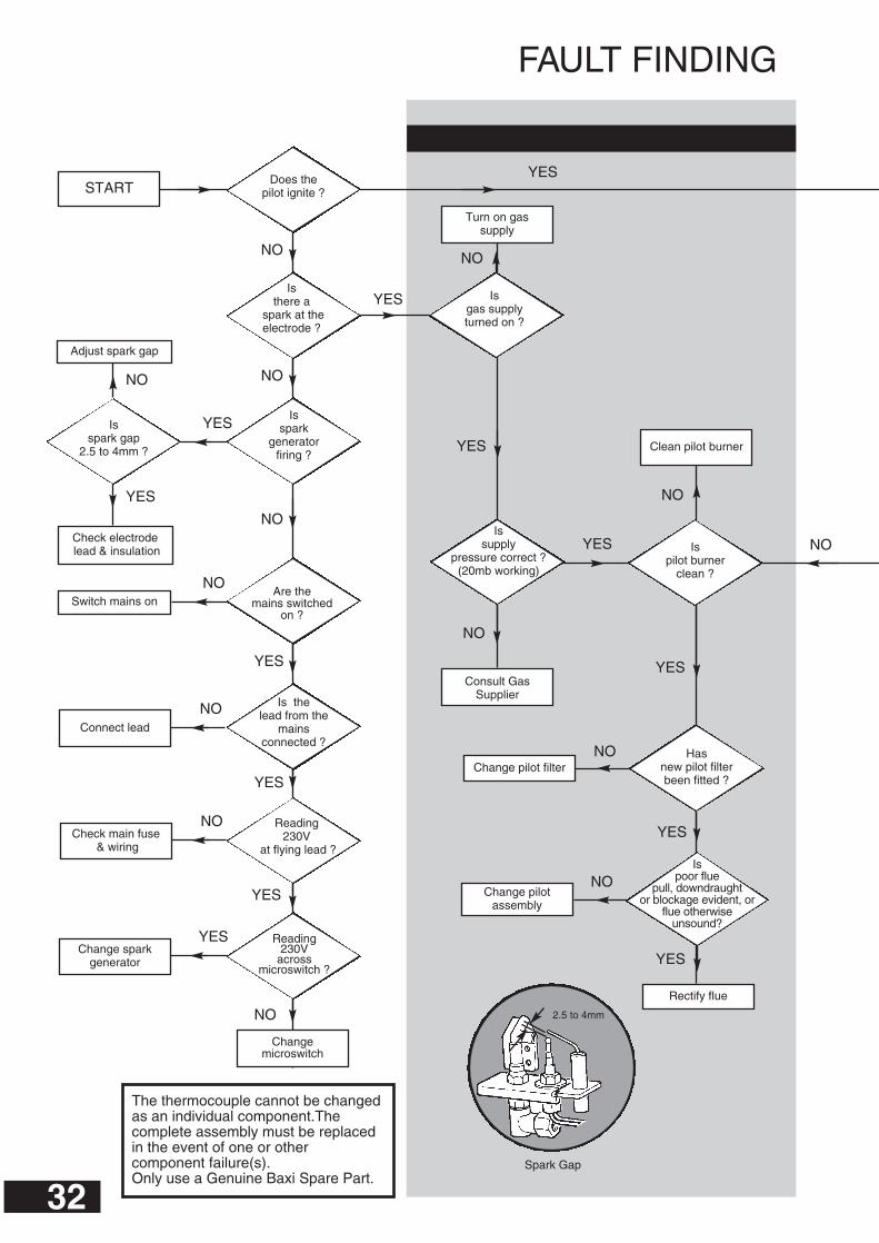
FAULT FINDING
32
Changemicroswitch
Are the mains switched
on ?
Isspark
generatorfiring ?
YES
NO
NO
NO
YES
NO
YES
YES
NO
Clean pilot burner
Change pilot filter
Rectify flue
YES
NO
NO
NO
YES
YES
Change sparkgenerator
Check main fuse& wiring
Connect lead
Switch mains on
Check electrodelead & insulation
Is there a
spark at theelectrode ?
Reading230V
acrossmicroswitch ?
Consult GasSupplier
Turn on gassupply
Is gas supplyturned on ?
Is supply
pressure correct ?(20mb working)
NO
YES
NO
YES
YES
NO Hasnew pilot filterbeen fitted ?
YES
NO
Adjust spark gap
NO
YES
Is pilot burner
clean ?
Change pilotassembly
NO
YES
Isspark gap
2.5 to 4mm ?
The thermocouple cannot be changedas an individual component.Thecomplete assembly must be replacedin the event of one or othercomponent failure(s).Only use a Genuine Baxi Spare Part.
Reading230V
at flying lead ?
Is thelead from the
mainsconnected ?
Is poor flue
pull, downdraught or blockage evident, or
flue otherwise unsound?
Spark Gap
Does thepilot ignite ?START
2.5 to 4mm

33
Open gas cocks
Contact the GasSupplier
Replace faulty bulb
Switch on bulbs
Isolate mains
Replace resistor
Fire satisfactory
Change the electromagnetic unit
Change pilotassembly
Is thermocouple
output within limits ?(9.4 - 13mV)
Ismeter pressure
correct ?
YES
NO
NO
YES
NO
Pipeworkundersized or
restricted
Issupply pressure
at appliance correct ?
NO
YES
YES
YES
YES
NO
NO
NO
NO
YES
YES
YES
NO
YES
Are gas cocks fully
open ?
Replace bothbulbs
Does onebulb light?
Doboth bulbs
light ?
Areplug & socket(under sparkgenerator)
connected?
230v across micro- switch whenoperated ?
230v acrossresistor ?
Are bulbsswitched on ?
NO
NO
YES
YES
YES
YES
Arepilot flames
stable and approx20mm long
YES
Isolate mains
Rectify flue
YES
NO
Connect plug and socket
Replace switch
Make good theconnection
Is thermocouple
connection sound ?
NO
Change pilotassembly
Is thermocouple
tipsound ?
NO
Cleanthermocouple tip
Isthermocouple
tipclean ?
NO
Doesthe fire remain
alight ?
Is poor flue
pull, downdraught or blockage evident, or
flue otherwise unsound?

34
It is important that the existing installation is correct andthat the flue is performing satisfactorily. Any remedialwork necessary should be completed before the newappliance is commissioned. Please read the ImportantInformation section on page 5.
WARNING: Renewal firefronts are fitted with anAtmospheric Sensing Device (A.S.D.). If they areinstalled in conjunction with a boiler NOT fitted withan A.S.D. (i.e. 401, 552, 45/3 & 57/3), under adverseflue conditions the boiler WILL NOT shut down.
NOTE: A permanent live is required for correct operationof the firefront.
Boiler Modification
Additional Installation Instructions
Bermuda RG3 Renewal G.C.No 37 075 06A
The kit supplied with Renewal appliances provides all thenecessary components to fit a Baxi Bermuda RG3Renewal firefront to the following Bermuda Boilers.
The Renewal Fires may be used with the followingBoilers:
Bermuda 401 G.C.No 44 077 49Bermuda 552 G.C.No 44 077 50Bermuda 45/3 M G.C.No 44 077 61Bermuda 45/3 E G.C.No 44 077 60Bermuda 57/3 M G.C.No 44 077 63Bermuda 57/3 E G.C.No 44 077 62Bermuda 45/4 M G.C.No 44 077 71Bermuda 45/4 E G.C.No 44 077 73Bermuda 57/4 M G.C.No 44 077 72Bermuda 57/4 E G.C.No 44 077 74Bermuda 51/5 G.C.No 44 075 06
Existing FireREMOVING THE EXISTING FIRE
Isolate the gas and electrical supply, including anypermanent live, to the combined appliance.
Remove the controls cover panel from the front of the fire.
Remove the tap control knob. Disconnect the electricalsocket from the fire plug if fitted. Remove the screwssecuring the outercase to the innercase. Lift off theoutercase.
Turn the gas service tap to the "Boiler only" position byturning 1/4 turn clockwise.
Remove the radiants if fitted.
Disconnect the supply pipe at the fire inlet.
Remove any screws securing the fire to the wall. Pull thefire forward until the flue spigot is clear of the boiler hoodand lift away.
Remove and discard the fire supply pipe from the servicegas tap. Disconnect and discard any electrical wiringbetween the boiler input terminal and the fire.
Adhesive Foil Label
Renewal Firefront
NOTE: It is important at this stage to fit thecontrols heat shield supplied with the fire unit tothe boiler front panel.
Remove and discard the controls heat shieldprovided with the boiler and fit the new controls heatshield using the screws previously removed.
Fit the additional valve heat shield in position overthe gas valve by engaging the two clips and pushinghome as shown above.
Check the data badge on the back boiler. If the boilerinternal wiring is not depicted, take the foil label fromthe kit and attach it below the data badge on theboiler front door.
If a radiant firefront has been installed previously itwil l be necessary to unscrew and remove theextension plate from the boiler controls heat shield.Once removed this item can be discarded.
BERMUDA 401 & 552New ControlsHeat Shield
Controls HeatShield
Valve HeatShield
BERMUDA 45/3, 57/3, 45/4, 57/4 & 51/5
Extension Plate
Bermuda 57/3 Illustrated

35
SupportBrackets(401 Only)
Fire SupportPlate
Fire SupportPlate
Fire Support Plate - Bermuda 401 & 552
Fire Support Plate - Bermuda 45/3, 57/3, 45/4, 57/4 & 51/5
BERMUDA 45/3, 57/3, 45/4, 57/4 & 51/5
BERMUDA 401 & 552
If the fire is wall mounted remove and discard the existingsupport frame. (Bermuda 401 only) Retain the twosupport brackets. These will be needed in wall mountingthe renewal fire.
If the fire is hearth mounted ensure that the base of thebuilders opening and the front hearth are at the samelevel.
Refer to "Site Requirements" (page 7) and prepare thewall surface to the dimensions specified.
WALL FIXING
Two wall fixing plates are supplied in the Renewal Kit,one for Bermuda 401/552 and one for Bermuda 45/3,57/3, 45/4, 57/4 & 51/5.
BERMUDA 401 & 552
Take the fire support plate from the fire unit packagingand loosely attach it beneath the boiler base protrudingfrom the fireplace opening using the M5 Nuts and screwsprovided. Use the centre group of holes at each side.
NOTE: If the fire is being used with a Bermuda 401 boilerunit, the support brackets from the previous plate must befitted before the fire support plate can be fixed in place.
Push the support plate backwards until it touches thesurround or wall face and tighten the screws to lock it inposition.
BERMUDA 45/3, 57/3, 45/4, 57/4 & 51/5
Take the fire support plate from the fire unit packagingand loosely attach it above the boiler base protrudingfrom the fireplace opening using the screws provided.Use the slots at each side.
Push the support plate backwards until it touches thesurround or wall face and tighten the screws to lock it inposition.
WIRING
When connecting the firefront wire to the plug on theboiler base tray refer to pages 8-12 of these instructions.
FIRE SUPPLY PIPE
Two fire supply pipes are supplied in the Renewal Kit, onefor Bermuda 401 & 552 and one for Bermuda 45/3, 57/3,45/4, 57/4 & 51/5. The smaller (6mm) diameter one is forBermuda 45/3, 57/3, 45/4, 57/4 & 51/5 installations.
TO CONTINUE FITTING THE FIREFRONT REFER TOTHE INSTALLATION CHAPTER OF THESEINSTRUCTIONS.
Bermuda 57/4 Illustrated

Comp No 237641 - Iss 6 - 1/03
B A X I P O T T E R T O NBrownedge Road Bamber Bridge Preston Lancashire PR5 6SNAfter Sales Service 08706 096 096 Technical Enquiries 08706 049 049www.baxi.co.uk