INSTALLATION AND SERVICING - Ideal Boilers · INSTALLATION AND SERVICING EVOMAX 30 40 60 80 100 120...
66
INSTALLATION AND SERVICING EVOMAX 30 40 60 80 100 120 150 30P 40P 60P 80P May 2017 UIN 206210 A14 When replacing any part on this appliance, use only spare parts that you can be assured conform to the safety and performance specification that we require. Do not use reconditioned or copy parts that have not been clearly authorised by Ideal. For the very latest copy of literature for specification and maintenance practices visit our website www.idealcommercialboilers.com where you can download the relevant information in PDF format.
Transcript of INSTALLATION AND SERVICING - Ideal Boilers · INSTALLATION AND SERVICING EVOMAX 30 40 60 80 100 120...

INSTALLATION ANDSERVICINGEVOMAX30 40 60 80 100 120 15030P 40P 60P 80P
May 2017UIN 206210 A14
When replacing any part on this appliance, use only spare parts that you can be assured conform to the safety and performance specification that we require. Do not use reconditioned or copy parts that have not been clearly authorised by Ideal.
For the very latest copy of literature for specification and maintenance practices visit our website www.idealcommercialboilers.com where you can download the relevant information in PDF format.

2 EVOMAX - Installation & Servicing
MODEL
SYMBOL UNITS 30 30P 40 40P 60 60PCondensing Boiler n/a n/a yes yes yes yes yes yes
Low Temperature Boiler n/a n/a no no no no no no
B1 Boiler n/a n/a no no no no no no
Cogeneration Space Heater n/a n/a no no no no no no
Equipped with a Supplementary Heater n/a n/a no no no no no no
Combination Heater n/a n/a no no no no no no
Nominal Heat Output for Space HeatingFull Load P4 kW 30 30 40 40 60 60Part Load P1 kW 9.7 9.7 13 13 19.5 19.5Auxiliary Electricity ConsumptionFull Load elmax kW 0.134 0.134 0.135 0.135 0.092 0.092Part Load elmin kW 0.03 0.03 0.03 0.03 0.026 0.026Standby PSB kW 0.006 0.006 0.006 0.006 0.006 0.006Seasonal Space Heating Energy EfficiencyFull Load ƞ4 % 89.6 91.6 89.6 91.5 89.7 91.7Part Load ƞ1 % 98.4 99.6 97.8 99.5 97.9 99.7Standby Loss Pstby kW 0.08 0.08 0.08 0.08 0.11 0.11Ignition Pign kW 0 0 0 0 0 0
Emissions NOx mg/kWh 28 71 35 72 28 73Annual Energy Consumption QHE GJ 93.0 91.9 123.9 122.6 185.8 181.9Sound Power Level, Indoors LWA dB 53 53 53 53 52 52
ERP DATA

3EVOMAX - Installation & Servicing
EVOMAX HEAT BOILERIdeal BoilersERP DATA
SYMBOL UNITS MODEL30 30P 40 40P 60 60P
Condensing boiler YesSeasonal Space heating efficiency class ARated heat output kW 30 30 40 40 60 60Seasonal space heating energy efficiency ƞs % 93* 93* 93* 93* 93* 93*Annual energy consumption QHE GJ 92.9 91.9 123.9 122.6 185.8 181.9Sound power level, indoors LWA dB 53 53 53 53 52 52
Seasonal Space Heating Energy Efficiency of the Boiler *%
Temperature control (from fiche of temperature control) %
Class I Class II Class III Class IV Class V Class VI Class VII Class VIII1% 2% 1.5% 2% 3% 4% 3.5% 5%
PRODUCT FICHE
The energy efficiency of the package of products provided for in this document may not correspond to its actual energy efficiency once installed in a building, as the efficiency is influenced by further factors such as heat loss in the products in relation to the building size and its characteristics
Collector Size(in m2)
Tank Volume(in m3)
Collector Efficiency
(in %)
Tank ratingA* = 0.95A = 0.91B = 0.86C = 0.83
D-G = 0.81
Solar Contribution (from fiche of solar device)
Seasonal Space Heating Energy Efficiency of Package TOTAL: A+B+C=
Seasonal Space Heating Energy Efficiency Class of Package
= (‘III ’x + ‘IV ’ x ) x 0.9 x ( / 100 x = %
%
GG F E D C B A A+ A++ A+++
< 30% ≥ 30% ≥ 34% ≥ 36% ≥ 75% ≥ 82% ≥ 90% ≥ 98% ≥ 125% ≥ 150%
A
B
C

4 EVOMAX - Installation & Servicing

5EVOMAX - Installation & Servicing

6 EVOMAX - Installation & Servicing
GENERAL
Note.
Natural gas consumption is calculated using a calorific value of 37.8MJ/m3 (1038Btu/ft3) gross or 34 MJ/m3 (910 Btu/ft3) nett at 15oC and 1013.25 mbar.a. For l/s divide the gross heat input (kW) by the gross C.V. of the
gas (MJ/m3)b. For ft/h3 divide the gross heat input (Btu/h) by the gross C.V. of
the gas (Btu/ft3).c. For m3/h multiply l/s by 3.6. d. 1kW = 3412 BTU/hr. e. 1m3 = 35.3ft3 f. 1mg/kWh (NOx) = 0.568 ppm DAF (natural gas).
Propane gas consumption is calculated using a calorific value of 95.7 MJ/m3 (2500 Btu/ft.3) gross or 88.0 MJ/m3 (2300 Btu/ft.3) net at 15oC and 1013.25 mbar.To obtain the fuel consumption in liquid form divide the above figures by 270.
* The value is used in the UK Government’s Standard Assessment Procedure (SAP) for energy ratings of dwellings. The test data from which it has been calculated have been certified by a notified body.
Table 2 General Data
HEALTH & SAFETY DOCUMENT NO. 635The electricity at work regulations, 1989. The manufacturer’s notes must NOT be taken, in any way, as overriding statutory obligations.
IMPORTANT. These appliances are CE certified for safety and performance. It is, therefore, important that no external control devices, e.g. flue dampers, economisers etc., are directly connected to these appliances unless covered by these Installation and Servicing Instructions or as otherwise recommended by Ideal Boilers in writing. If in doubt please enquire.
Any direct connection of a control device not approved by Ideal Boilers could invalidate the certification and the normal appliance warranty. It could also infringe the Gas Safety Regulations and the above regulations.
Evomax Model 30 30P 40 40P 60 60P 80 80P 100 120 150Boiler Output
(non-condensing)Mean 70°C
Max kW 30 30 40 40 60 60 80 80 100 120 150
Min kW 6 6 8 8 12 15 16 20 20 24 30
Boiler Output(condensing)Mean 40°C
Max kW 31.54 30.9 42.0 41.2 63.5 62.1 84.4 82.6 103.9 124.7 158.0
Min kW 6.5 6.4 8.5 8.3 12.7 15.5 17.2 21.2 21.6 26.0 32.5
Boiler InputMax Rate
Nett kW 30.4 30.4 40.5 40.5 60.8 60.7 82.0 81.9 102.4 122.9 153.7
Gross kW 33.7 33 44.9 44 67.4 66 90.9 88.9 113.6 136.4 170.5
Boiler InputMin Rate
Nett kW 6.1 6.1 8.1 8.1 12.2 15.2 16.4 20.5 20.5 24.6 30.7
Gross kW 6.7 6.6 9.0 8.8 13.5 16.5 18.2 22.2 22.7 27.3 34.1
Gas Rate Max Rate m3/hr 3.2 1.26 4.3 1.69 6.4 2.53 8.7 3.41 10.8 13.0 16.2
Flue Gas Flow Rate Max Rate m3/hr 47.6 46.5 63.4 62.1 95.1 93.1 128.3 125.4 160.3 192.5 240.7
CO2 (±0.5%)Max Rate % 9.7 11.4 9.7 11.4 9.7 11.4 9.7 11.4 9.7 9.7 9.7Min Rate % 8.7 10.2 8.7 10.2 8.7 10.5 8.7 10.5 8.7 8.7 8.7
NOx weighted mg/kWh 31.0 79 39.1 80 32.3 83.8 39.8 68 39.6 38.8 38.1
EfficiencySeasonal % 96.7 97.2 96.2 96.7 96.4 96.9 97.2 97.7 96.7 96.6 96.7
*SEDBUK 2009 % 89.6 90.6 89.3 90.3 89.4 90.5 n/a n/a n/a n/a n/a
Evomax Model 30 30P 40 40P 60 60P 80 80P 100 120 150Gas Supply 2H – G20 – 20mbar / 3P - G31 - 37mbarGas Supply Connection G 3/4Flow Connection G1 1/4Return Connection G1 1/4Max Pressure (sealed sys) Bar (psi) 4.0 (60)Maximum Static Head m 40.7Electricity Supply 230V - 50HzFuse Rating A 4.0Power Consumption W 126 207 131 265 370 403 400IP Rating IP20Nominal flue dia - Concent. 80/125 100/150Condensate Drain 25Water Content L 3.0 5.0 7.0 9.2Dry Weight Kg 49 60.30 75.70 89.75
Table 1 Performance Data (Natural Gas)

7EVOMAX - Installation & Servicing
GENERAL
CONTENTSBoiler Assembly - Exploded view. .................................13Boiler Clearances. ...........................................................11Commissioning and Testing. ..........................................42Electrical Connections. ...................................................27Electrical Supply..............................................................10Fault Finding. ...................................................................53Flue Installation. ................................................................9Flue Kits. ..........................................................................17Gas Safety Regulations ...................................................8Gas Supply. ........................................................................9Hydraulic Resistance. .....................................................10Introduction. .......................................................................8Initial Lighting. .................................................................43Installer Connections. .....................................................28Installation. .......................................................................13Mounting Boiler. ..............................................................16Option Kits. ........................................................................8Performance Data. .............................................................6Servicing. .........................................................................45Short List of Parts. ..........................................................63Ventilation. .......................................................................16Water Circulation. ..............................................................9Water Connections. .........................................................26Water System Requirements. .........................................12Water Treatment. .............................................................10Wiring Diagrams. .............................................................29
Key to symbols
IE = Ireland, GB = United Kingdom (Countries of destination)
PMS = Maximum operating pressure of water
C13 C33 = A room sealed appliance designed for connection via ducts to a horizontal or vertical terminal, which admits fresh air to the burner and discharges the products of combustion to the outside through orifices which, in this case, are concentric. The fan is up stream of the combustion chamber.
B23 = An appliance intended to be connected to a flue which evacuates the products of combustion to the outside of the room containing the boiler. The combustion air is drawn directly from the room. The fan is up stream of the combustion chamber.
II2H3P = An appliance designed for use on 2nd and 3rd Family gases.
EVOMAX30, 40, 60, 80, 100, 120, & 15030P, 40P, 60P & 80PNatural Gas & LPGDestination Countries: GB, IE
Boiler size G.C. Appliance No. PI No. (Benchmark No.)
30 41-750-33A 86-CL-16640 41-750-34A 86-CL-16660 41-750-35A 86-CL-16680 41-750-36A 86-CL-166100 41-750-37A 86-CL-166120 41-750-38A 86-CL-166150 41-750-39A 86-CL-16630P 41-750-40 86-CL-16640P 41-750-41 86-CL-16660P 41-750-42 86-CL-16680P 41-750-43 86-CL-166
NOTE TO THE INSTALLER: LEAVE THESE INSTRUCTIONS ADJACENT TO THE GAS METER.

8 EVOMAX - Installation & Servicing
GENERAL
INTRODUCTIONThe EVOMAX boilers are fully automatically controlled, wall mounted, fanned, super efficient condensing appliances.The EVOMAX condensing boilers can be installed either on the wall or into a prefabricated floor mounted frame.The boilers are suitable for use with a room sealed flue or open flue application.Through a sophisticated control system combined with premix burner arrangement the boilers are capable of high seasonal efficiencies of >96% and low emissions.These boilers are certified to meet the requirements of the EC Gas Appliance Directive, Boiler Efficiency Directive, EMC and Low Voltage Directive.Note. These boilers cannot be used on systems that include gravity circulation.The boiler are suitable for connection to fully pumped, open vented or sealed water systems. Adequate arrangements for completely draining the system by provision of drain cocks MUST be provided in the installation pipework.
OPTIONAL EXTRA KITS• Vertical Roof Flue Kit 80/125• Vertical Roof Flue Kit 100/150• Horizontal Wall Flue Kit 80/125• Horizontal Wall Flue Kit 100/150• Open Flue Kit 80• Open Flue Kit 100• Cascade Flue Kit• Pitched and Flat Roof Tiles • Frame and Header Kits• Pump Kits• Programmable Room Thermostat Kit• Modulating Sequencer Kit• Outside Sensor Kit• Tank Sensor Kit• Room Sensor Kit• Safety Interlock Kit• Plume Kit• Propane to Natural Gas Conversion Kit Please note propane variants of the Evomax are Cat II2H3P (20/37) and
may be converted to natural gas operation only using the approved conversion kit supplied by Ideal.
Natural gas variants of the Evomax are Cat I2H and cannot be converted to propane operation.
SAFETYCurrent Gas Safety (Installation and Use) Regulations or rules in forceThe appliance is suitable only for installation in GB and IE and should be installed in accordance with the rules in force.In GB, the installation must be carried out by a Gas Safe Registered Engineer or in IE by a competent person. It must be carried out in accordance with the relevant requirements of the:• Gas Safety (Installation and Use) Regulations• The appropriate Building Regulations either The Building
Regulations, The Building Regulations (Scotland), Building Regulations (Northern Ireland).
• The Water Fittings Regulations or Water byelaws in Scotland.• The Current I.E.E. Wiring Regulations.Where no specific instructions are given, reference should be made to the relevant British Standard Code of Practice.In IE, the installation must be carried out by a Competent Person and installed in accordance with the current edition of I.S.813
“Domestic Gas Installations” or I.S. 820 “Non-Domestic Gas Installations” as appropriate, the current Building Regulations and reference should be made to the current ETCI rules for electrical installation.The Evomax boilers have been tested and certified to; EN 483, EN 677, PREN 15420, BSEN 15417, BSEN 656, BSEN 60335-2-102, BSEN 55014-1 and BSEN 55014-2 for use with Natural Gas & LPG.Detailed recommendations are contained in the following Codes of Practice:BS. 6891 Installation of low pressure gas pipework of up to
28mm (R1) in domestic premises (2nd family gas).BS. 5482 Pt. 1 Domestic butane and propane gas burning
installations.BS. 5440 Inst. and maintenance of flues and ventilation for gas
appliances of rated input not exceeding 70kW net (1st, 2nd and 3rd family gases).
Part 1 Specification for installation of flues. Part 2 Specification for installation and maintenance of
ventilation for gas appliances.BS. 6644 : 2005 Installation of gas fired hot water boilers of rated
inputs between 70kW and 1.8MW (net) (2nd and 3rd family gases).
BS. 6798 Installation and maintenance of gas fired hot water boilers of rated input not exceeding 70kW net.
BS. 6880 Low temperature hot water heating systems of output greater than 45kW.
Part 1 Fundamental and design considerations. Part 2 Selection of equipment. Part 3 Installation, commissioning and maintenance.
BSEN.12828:2003 Heating Systems in buildings: Design for water based systems.
BSEN.12831:2003 Heating Systems in buildings: Method for calculation of the design heat load.
BSEN.13831 Specification for: Expansion vessels using an internal diaphragm, for sealed hot water heating systems.
BSEN.14336:2004 Heating Systems in buildings: Installation and commissioning of water based heating systems.
IGE/UP/1 Soundness testing and purging of industrial and commercial gas installation.
IGE/UP/2 Gas installation pipework, boosters and compressors on industrial and commercial premises.
IGE/UP/10 Installation of gas appliances in industrial and commercial premises.
Where reference is made throughout these instructions I.S.813:2002 “Domestic Gas Installations” reference should also be made to I.S.820:2000 “Non-Domestic Gas Installations” as applicable.
SAFE HANDLINGThis boiler may require 2 or more operatives to move it to its installation site, remove it from its packaging base and during movement into its installation location. Manoeuvring the boiler may include the use of a sack truck and involve lifting, pushing and pulling.Caution should be exercised during these operations.Operatives should be knowledgeable in handling techniques when performing these tasks and the following precautions should be considered:• Grip the boiler at the base.• Be physically capable.• Use personal protective equipment as appropriate, e.g. gloves,
safety footwear.

9EVOMAX - Installation & Servicing
GENERAL
During all manoeuvres and handling actions, every attempt should be made to ensure the following unless unavoidable and/or the weight is light.• Keep back straight.• Avoid twisting at the waist.• Avoid upper body/top heavy bending.• Always grip with the palm of the hand.• Use designated hand holds.• Keep load as close to the body as possible.• Always use assistance if required.
SAFE HANDLING OF SUBSTANCESNo asbestos, mercury or CFCs are included in any part of the boiler or its manufacture.
LOCATION OF BOILERThe boiler must be installed on a flat and vertical wall, capable of adequately supporting the weight of the boiler and any ancillary equipment or on a boiler frame supplied in kit form by Ideal Boilers.
The boiler must not be fitted outside.
GAS SUPPLYThe local gas supplier should be consulted, at the installation planning stage, in order to establish the availability of an adequate supply of gas. An existing service pipe must NOT be used without prior consultation with the local gas supplier.A gas meter can only be connected by the local gas supplier or by a Gas Safe Registered Engineer or in IE by a competent person.An existing meter should be checked, preferably by the gas supplier, to ensure that the meter is adequate to deal with the rate of gas supply required. A minimum working gas pressure of 17.5mbar MUST be available at the boiler inlet for Natural gas and 37mbar for Propane.Do not use pipes of smaller size than the boiler inlet gas connection.The complete installation MUST be tested for gas soundness and purged in accordance with the appropriate standards listed on page 8.
FLUE INSTALLATION
DANGER; ONLY USE IDEAL FLUE GAS SYSTEMS. THE CE MARK IS VALID ONLY IF THE APPLIANCE IS OPERATED WITH IDEAL FLUE KITS. OTHER FLUE SYSTEMS ARE NOT TESTED WITH THIS APPLIANCE.
The flue kits are suitable for use with the EVOMAX boiler only.
These kits and the associated options are suitable for both roof and wall mounting applications. The Horizontal Wall Flue Kit is not for use with Evomax 150 boilers in compliance with the requirements of the Clean Air Act Memorandom.
The roof flue kits are suitable for both flat and pitched roof termination, using either concentric or flue only terminals.
Connection to the top of the boiler is made using a separately supplied vertical connector in concentric and open flue configurations (supplied in our optional extra kits).
Additional information covering the selection and installation can be found with this booklet.
Weather ProofingWhere the flue passes through the roof line an adequate seal must be made. This can be achieved by using either:
• Flat weather collar• Pitched weather collar
Flue duct extension kits are available for concentric flue configuration. These packs contain additional 1 metre ducts and may be cut to the desired length.
Flue duct extension kits are available for open flue configurations. These packs contain 2 x 1 metre ducts and may be cut to the desired length.
If obstructions prevent direct flue routing then both 90o and 45o elbows can be provided to offset the flue system.
Terminal PositionDue to the high efficiency of the boilers pluming will occur. For this reason, vertical termination is recommended, and in any case, terminal positions which could cause problems should where possible be avoided. Particular care should be taken in the case of large multiple boiler installations, and complying with the requirements of the Clean Air Act.
IMPORTANTIt is the responsibility of the installer to ensure, in practice, that products of combustion discharging from the terminal cannot re-enter the building or any other adjacent building through ventilators, windows, doors, other sources of natural air infiltration, or forced ventilation / air conditioning.
If this should occur the appliance MUST be turned OFF, labelled as ‘unsafe’ and corrective action taken.
Where the lowest part of the terminal is fitted less than 2m (80”) above a balcony, above ground or above a flat roof to which people have access then the terminal MUST be protected by a purpose designed guard. The minimum spacing between the balcony and the terminal should be 75mm, in order to allow a terminal guard to be fitted.
Terminal guards are available from boiler suppliers - for all requirements contact:
Grasslin (UK) Ltd., Tower House, Vale Rise, Tonbridge, Kent TN9 1TB. Tel: +44 (0) 1732 359 888. Fax: +44 (0) 1732 354 445www.tfc-group.co.uk
Ensure that the guard is fitted centrally.
The air inlet/products outlet duct and the terminal of the boiler MUST NOT be closer than 25mm (1”) to combustible material. Detailed recommendations on the protection of combustible material are given in BS. 5440-1: 2008. In IE refer to I.S.813:2002.
The flue must be installed in accordance with Building Regulations and the recommendations of BS. 5440-1:2008 for inputs up to 70kW nett. For larger installation BS. 6644 should be complied with. In IE refer to I.S.820:2000.
!

10 EVOMAX - Installation & Servicing
GENERAL
WATER CIRCULATION SYSTEMThe system pump MUST be connected to the boiler, see below.
The boiler must NOT be used for direct hot water supply. The hot water storage cylinder MUST be of the indirect type.
Single feed, indirect cylinders are not recommended and MUST NOT be used on sealed systems.
The appliances are NOT suitable for gravity central heating nor are they suitable for the provision of gravity domestic hot water.
The hot water cylinder and ancillary pipework, not forming part of the useful heating surface, should be lagged to prevent heat loss and any possible freezing - particularly where pipes run through roof spaces and ventilated underfloor spaces.
The boiler must be vented.
Draining taps MUST be located in accessible positions, which permit the draining of the whole system - including the boiler and hot water storage vessel. They should be at least 1/2” BSP nominal size and be in accordance with BS. 2879.
The central heating system should be in accordance with the relevant standards listed on page 8.
Due to the compact nature of the boiler the heat stored within the castings at the point of shutdown of the burner must be dissipated into the water circuit in order to avoid overheating. In order to allow pump operation after burner shutdown the boiler control box incorporates a 4 minute pump overrun facility. In order to make use of this, the pump must be supplied from the terminals inside the boiler. Note: for pumps requiring a current greater than 1.3 amps inductive, they must be connected via a relay.When sizing pumps, reference should be made to the table below which show the boiler resistance against flow rates, to achieve the required temperature differential. Flow rates for common systems using either 11ºC, 15ºC or 20ºC temperature differentials and hydraulic resistances are given in the table below.
Flowrate (l/min) Hydraulic Resist-ance (mbar)
11ºC 15ºC 20ºC 11ºC 15ºC 20ºCEvomax 30/30P 39.1 28.7 21.5 425 225 127Evomax 40/40P 52.1 38.2 28.7 875 405 225Evomax 60/60P 78.2 57.3 43.0 435 180 83Evomax 80/80P 104.2 76.4 57.3 750 420 180Evomax 100 n/a* 95.6 71.7 n/a* 315 134Evomax 120 n/a* n/a* 86.0 n/a* n/a* 218Evomax 150 n/a* n/a* 107.5 n/a* n/a* 230
* Models with n/a are due to excessive flowrates which will cause erosion of the casting.
Note.• With the boiler firing at maximum rate, the temperature
differential should not be less than figures quoted in table above. High flow rates required for lower temperature differentials could lead to errosion of the heat exchanger water ways.
• With the boiler firing at minimum rate, the temperature differential should not be greater than 35oC. Lower flow rates generating higher temperature differentials will lead to lock out of the boiler.
• The lower the return temperature to the boiler, the higher the efficiency.
In installations where all radiators have been provided with thermostatic radiator valves, it is essential that water circulation through the boiler is guaranteed. This can be best achieved by means of a differential pressure valve, which is installed in a bypass between the flow and return pipes. The bypass should be fitted at least 6m from the boiler, and should use a minimum size of 28mm pipe. The bypass should be capable of allowing a minimum flow rate to achieve a temperature differential of no greater than 35oC at minimum rate.
WATER TREATMENTThese boilers incorporate an ALUMINIUM heat exchanger.IMPORTANT. The application of any other treatment to this product may render the guarantee of Ideal Boilers INVALID.Ideal Boilers recommend Water Treatment in accordance with Guidance Notes on Water Treatment in Central Heating Systems.Ideal Boilers recommend the use of Fernox Copal or MB1 or GE Betz Sentinel X100 inhibitors and associated water treatment products, which must be used in accordance with the manufacturers’ instructions.For further information contact:Fernox Manufacturing Co. Ltd., Cookson Electronics, Forsyth Road, Sheerwater, Woking, Surrey, GU21 5RZTel: +44 (0) 1799 521133orSentinel Performance Solutions, The Heath Business and Technical Park, Runcorn, Cheshire, WA7 4QXTel: 0800 389 4670www.sentinel-solutions.net
Notes.1. It is most important that the correct concentration of the water
treatment products is maintained in accordance with the manufacturers’ instructions.
2. If the boiler is installed in an existing system any unsuitable additives MUST be removed by thorough cleansing. BS7593:1992 details the steps necessary to clean a domestic heating system.
3. In hard water areas, treatment to prevent limescale may be necessary - however the use of artificially softened water is NOT permitted.
4. Under no circumstances should the boiler be fired before the system has been thoroughly flushed.
ELECTRICAL SUPPLYWiring external to the appliance MUST be in accordance with the current I.E.E. (BS7671) Wiring Regulations and any local regulations which apply. For Ireland reference should be made to the current ETCI rules for electrical installations
The point of connection to the mains should be readily accessible and adjacent to the boiler.
CONDENSATE DRAINRefer to Frames 22, 23 & 58A condensate drain is provided on the boiler. This drain must be connected to a drainage point on site. All pipework and fittings in the condensate drainage system MUST be made of plastic - no other materials may be used.IMPORTANT.Installation must be in accordance with BS 6798.The drain outlet on the boiler is sized for standard 21.5mm (3/4”) overflow pipe. It is a universal fitting to allow use of different brands of pipework.

11EVOMAX - Installation & Servicing
GENERAL
1 BOILER CLEARANCES AND CONNECTIONS
The following minimum clearances must be maintained for operation and servicing.
Front of boiler - 450mmSides of boiler - 25mmAbove boiler - dependent upon the flue system see drawingsBelow boiler - 300mmClearance between multiple boiler installations - 25mm
80/125 Concentric Flue ConnectorEVOMAX 30, 40, 60 & 80Minimum boiler top clearances:for vertical flue 200mmfor horizontal flue 350mm (415mm for 100/150)for open flue 350mm
100/150 Concentric Flue ConnectorEVOMAX 100, 120 & 150Minimum boiler top clearances:for vertical flue 200mmfor horizontal flue 370mmfor open flue 350mm
Flue
cen
trelin
e
im92
45 X=2
24.5
(80/
125)
X=2
89.5
(100
/150
)*
* with 100/150 adaptor (See Frame 13)
Flue
cen
trelin
e
X=23
2
RF
2544
500
‘C’ ‘B’
‘A’
850
59 59155
8168Gas
Flow Return
299
Gas
Pip
e
Flow
/Ret
urn
Con
dens
ate
Dra
in
Flue
Cen
tre L
ine
Flue
Cen
tre L
ine
2062
10-1
0155
Boiler Dim. A Dim. B Dim. C30, 40, 60, 80 360 130 118100, 120 520 226 118150 610 233 120

12 EVOMAX - Installation & Servicing
GENERAL
Feed/expansioncistern 500mm
minimum
3000mmminimum
Systemflow topump
Inverted coldfeed entry
ColdFeed
Waterlevel
(cold)
Open vent
Systemreturn
Connectionsto boiler
ima5351
3000
min
imum
3 SEALED SYSTEM REQUIREMENTSNote. The method of filling, refilling, topping up or flushing sealed primary hot water circuit from the mains for a non-domestic property is shown below.
1. General a. Detail reference should be made to the appropriate
standards listed on page 8. The information and guidance given below is not intended to override any requirements of these publications or the requirements of the local authority, gas or water undertakings.
b. The installation should be capable of working with flow temperatures of up to 90oC and a temperature differential of up to 20oC.
c. All components of the system, including the heat exchanger of the indirect cylinder, must be suitable for a working pressure of 4 bar (60 lbf/in2) and temperature of 110oC. Care should be taken in making all connections so that the risk of leakage is minimised.
d. The boiler is fitted with an automatic air vent, located in the left top side of the interior. This air vent must never be shut off, as this could result in dry firing of the boiler and subsequent damage to the heat exchanger.
2. Safety Valve A spring loaded safety valve complying with
the relevant requirements of BS. 6759 Pt. 1 must be fitted in the flow pipe as close to the boiler as possible and with no intervening valve or restriction. The valve should have the following features:
a. A non-adjustable preset lift pressure not exceeding 4 bar (60 lbf/in2).
b. A manual testing device.
c. Provision for connection of a discharge pipe. The valve or discharge pipe should be positioned so that the discharge of water or steam is visible, but will not cause hazard to user or plant.
3. Pressure Gauge A pressure gauge covering at least the range 0-4 bar must
be fitted to the system. The gauge should be easily seen from the filling point and should preferably be connected at the same point as the expansion vessel.
4. Expansion Vessel Expansion vessels used must comply with BS. EN 13831.
Connection to the system must not incorporate an isolating valve.
2 OPEN VENTED SYSTEM REQUIREMENTS
Detail reference should be made to the appropriate standards listed on page 8.
The information and guidance given below is not intended to override any requirements of the above publications or the requirements of the local authority, gas or water undertakings.
The vertical distance between the pump and feed/expansion cistern MUST comply with the pump manufacturer’s minimum requirements, to avoid cavitation. Should these conditions not apply either lower the pump position or raise the cistern above the minimum requirement specified by Ideal Boilers. The isolation valves should be fitted as close to the pump as possible.
The boiler is fitted with an automatic air vent, located in the left top side of the interior. This air vent must never be shut off, as this could result in dry firing of the boiler and subsequent damage to the heat exchanger.
CV CVResillient
seat controlvalves
Supplypipe
DTCV = Control ValveDT = Drain Tap
Airgap
Tundish
Strainer
Type BA backflowprevention device
(RP2 valve assembly)
primary flowand return
ima7
349
13EVOMAX - Installation & Servicing
INSTALLATION
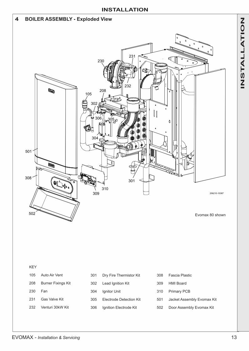
4 BOILER ASSEMBLY - Exploded View
INS
TA
LL
AT
ION
206210-10387
308
502
309
304
306
105
302
305
208232
230231
310
301
501
Evomax 80 shown
KEY
105 Auto Air Vent
208 Burner Fixings Kit
230 Fan
231 Gas Valve Kit
232 Venturi 30kW Kit
301 Dry Fire Thermistor Kit
302 Lead Ignition Kit
304 Ignitor Unit
305 Electrode Detection Kit
306 Ignition Electrode Kit
308 Fascia Plastic
309 HMI Board
310 Primary PCB
501 Jacket Assembly Evomax Kit
502 Door Assembly Evomax Kit

14 EVOMAX - Installation & Servicing
INSTALLATION
6 UNPACKING
5 PACKAGING REMOVAL
The boiler is supplied fully assembled in one pack. When unpacking the boiler check the contents against the list shown. Do not dispose of the packaging until all contents are accounted for, as some parts are held within the cardboard packing pieces.
• The boiler should be laying on its back with the straps removed.
• Carefully read the installation instructions before proceeding.
• Remove the outer packing sleeve.
• Remove the protective cardboard wall mounting template from the front of the boiler.
• Remove the packing piece from the top of the boiler.
• Check the contents against the list in Frame 6 ‘Unpacking’. Note: some items are contained within the top packing piece.
• The boiler may now be stood on its base, with the cardboard bottom packing piece still in place to protect the connections. Due care should be taken when standing up the boilers, with respect to their weights, see Table 2 on page 6.
INS
TA
LL
AT
ION
BA
C
D
F
E
G
H
J
Pack Contents
A Fully assembled boilerB Installation & Servicing/User InstructionsC Log BookD Wall mounting bracketE Wall mounting templateF Condensate TrapG M10 x 70 Hex Head Coach Screws - 6 offH M10 Wall Plug - 6 offJ Gas cock

15EVOMAX - Installation & Servicing
INSTALLATION
8 PREPARING THE WALL
7 WALL MOUNTING TEMPLATENote. The template shows the positions for the top fixing holes. Care must be taken to ensure the correct holes are drilled.
1. Tape template into the selected position.
2. Ensure squareness by hanging a plumbline.
3. Mark on to the wall:
a. The top 4 wall mounting plate screw positions.
b. The 2 boiler lower fixing positions using diagram below
c. The position of the flue duct. Mark the centre of the hole as well as the circumference.
4. Remove the template from the wall.
IMPORTANT. Ensure that, during the cutting operation, masonry falling outside of the building does not cause damage or personal injury.
1. Cut the flue hole ensuring that the hole is square to the wall. Both wall faces immediately around the cut hole should be flat.
2. Drill 4 boiler top fixing holes with a 12mm (1/2”) masonry drill and insert the plastic plugs provided, for the wall mounting plate.
3. Drill the 2 boiler lower fixing holes with a 12mm (1/2”) masonry drill, insert the plastic plugs provided .
4. Fix the wall bracket into place with 4 M10x70 hex head coach screws provided.
ima5
400
X
Y
26 52 78 104Vertical Offset From X mm
Distance from flue centre line (Y) to outside wall surface.For lengths greater than 4m, increase offset (X) by 26mm for every additional 1m.
4m
3m
2m
1m
Note: Horizontal flue runs must be inclined at 1.5-3o to the horizontal to allow condensate to drain back to the boiler.
INS
TA
LL
AT
ION
850m
m to
top
of b
oile
r18
mm
332mmØ12mm
BOILER LOWER FIXING POSITIONS

16 EVOMAX - Installation & Servicing
INSTALLATION
10 VENTILATION
9 MOUNTING THE BOILER
The ventilation requirements of these boilers is dependant on the type of flue system used, and their heat input. All vents must be permanent with no means of closing, and positioned to avoid accidental obstruction by blocking or flooding.
EVOMAX 30/30P, 40/40P, 60/60PDetail reference should be made to BS. 5440 Pt. 2. In IE refer to the current edition of I.S. 813.
The following notes are for general guidance only:
If installed as a room sealed appliance in a room or internal space, then no purpose provided ventilation is required.
If installed as an open flued appliance in a room or internal space then a permanent air vent is required. The sizes given below are for vents directly communicating with outside air. For other situations refer to BS. 5440 Pt. 2. In IE refer to the current edition of I.S. 813.
• Due care should be taken when lifting the boilers, with respect to their weights, see Table 2 on Page 6. Also refer to Safe Handling on Page 8.
1. Lift the boiler onto the wall mounting plate as shown. Note: It is not necessary to hold the boiler at an angle to engage the wall mounting plate.
2. Using the remaining coach screws, secure the bottom of the boiler to the wall through the attached brackets.
Boiler Size 30 & 30P 40 & 40P 60 & 60P
Minimum vent free 117 167 269area (cm2)
If installed in a compartment, then permanent air vents are required at high and low level. These vents may communicate direct to outside air, or to a room/internal space. If to a room/internal space, it must itself be adequately ventilated as above.
The temperature within the boiler room shall not exceed 25ºC within 100mm of the floor, 32ºC at mid height and 40ºC within 100mm of the ceiling.
Evomax 80, 80P, 100, 120, 150 and multiple boiler applicationsDetail reference should be made to BS. 6644 for inputs between 70kW and 1.8MW (net). In IE refer to the current edition of I.S.820. The following notes are for general guidance only:
If ventilation is to be provided by means of permanent high and low vents communicating direct with outside air, then reference can be made to the sizes below. For other ventilation options refer to BS. 6644. In IE refer to the current edition of I.S.820.
EVOMAX 80, 80P, 100, 120 & 150
Open Flued InstallationsRequired area (cm2) per kW of total rated input (net)
Boiler room Enclosure Low level (inlet) 4 10 High level (outlet) 2 5
Note: Where a boiler installation is to operate in summer months (e.g. DHW) additional ventilation requirements are stated, if operating for more than 50% of time (refer to BS6644).
Room Sealed InstallationsA minimum of 2cm2 free area per kW of net heat input at both high and low level is required for boiler rooms. For enclosures refer to BS6644.
INS
TA
LL
AT
ION
Room Sealed Application - Min. Vent Free Area (cm2) Open Flue Application - Min. Vent Free Area (cm2)To a room or internal space To outside Air To a room or internal space To Outside Air
Boiler Size 30 40 60 30 40 60 30 40 60 30 40 60High Level 310 410 610 155 205 305 310 410 610 155 205 305Low level 310 410 610 155 205 305 620 820 1220 310 410 610
Evomax Ventilation Requirements (not exceeding 70kW net Input) when installed in a compartment
1
2
206210-10388
17EVOMAX - Installation & Servicing
INSTALLATION
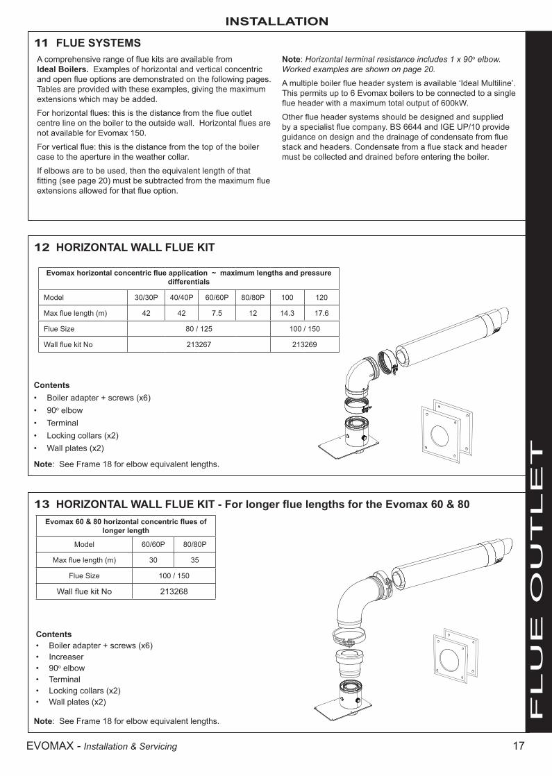
12 HORIZONTAL WALL FLUE KIT
Contents• Boiler adapter + screws (x6)• 90o elbow• Terminal• Locking collars (x2)• Wall plates (x2)
13 HORIZONTAL WALL FLUE KIT - For longer flue lengths for the Evomax 60 & 80
Contents• Boiler adapter + screws (x6)• Increaser• 90o elbow• Terminal• Locking collars (x2)• Wall plates (x2)
11 FLUE SYSTEMSA comprehensive range of flue kits are available from Ideal Boilers. Examples of horizontal and vertical concentric and open flue options are demonstrated on the following pages. Tables are provided with these examples, giving the maximum extensions which may be added.
For horizontal flues: this is the distance from the flue outlet centre line on the boiler to the outside wall. Horizontal flues are not available for Evomax 150.
For vertical flue: this is the distance from the top of the boiler case to the aperture in the weather collar.
If elbows are to be used, then the equivalent length of that fitting (see page 20) must be subtracted from the maximum flue extensions allowed for that flue option.
Note: Horizontal terminal resistance includes 1 x 90o elbow. Worked examples are shown on page 20.
A multiple boiler flue header system is available ‘Ideal Multiline’. This permits up to 6 Evomax boilers to be connected to a single flue header with a maximum total output of 600kW.
Other flue header systems should be designed and supplied by a specialist flue company. BS 6644 and IGE UP/10 provide guidance on design and the drainage of condensate from flue stack and headers. Condensate from a flue stack and header must be collected and drained before entering the boiler.
Note: See Frame 18 for elbow equivalent lengths.
Note: See Frame 18 for elbow equivalent lengths. F
LU
E O
UT
LE
T
Evomax horizontal concentric flue application ~ maximum lengths and pressure differentials
Model 30/30P 40/40P 60/60P 80/80P 100 120
Max flue length (m) 42 42 7.5 12 14.3 17.6
Flue Size 80 / 125 100 / 150
Wall flue kit No 213267 213269
Evomax 60 & 80 horizontal concentric flues of longer length
Model 60/60P 80/80P
Max flue length (m) 30 35
Flue Size 100 / 150
Wall flue kit No 213268

18 EVOMAX - Installation & Servicing
INSTALLATION
16 OPEN FLUE KITS
Contents158662 / 158663• Boiler adapter + screws (x6)• Air inlet grille
158771 / 158772• Extension tube (x2)*
158769 / 158770• Terminal
Note: See Frame 18 for elbow equivalent lengths.
RF
2501
14 VERTICAL ROOF FLUE KIT
Contents• Boiler adapter + screws (x6)• Terminal• Locking Collar• Finishing plates (x2)• Bracket
RF
2498
Note: See Frame 18 for elbow equivalent lengths.
15 VERTICAL ROOF FLUE KIT -
Contents• Boiler adapter + screws (x6)• Increaser• Terminal• Locking Collars (x2)• Finishing plates (x2)• Bracket R
F 24
99
Note: See Frame 18 for elbow equivalent lengths.
F
LU
E O
UT
LE
T
Evomax vertical concentric flue application ~ maximum lengths and pressure differentials
Model 30/30P 40/40P 60/60P 80/80P 100 120 150Max flue length (m) 42 42 7.5 12 14.3 17.6 7.5Flue Size 80 / 125 100 / 150Vertical flue kit No 213264 213266
Evomax 60 & 80 vertical concentric flues of longer length
Model 60/60P 80/80PMax flue length (m) 30 35
Flue Size 100 / 150Vertical flue kit No 213265
Evomax open flue application ~ maximum lengths and pressure differentials
Model 30/30P 40/40P 60/60P 80/80P 100 120 150Max flue length (m) 65 70 25 22 20 49 32Max flue press diff (Pa) 140 225 150 312 220 365 430Flue Size 80/125 100/150Open flue kit No 158662 + 158771 + 158769 158663 + 158772 + 158770

19EVOMAX - Installation & Servicing
INSTALLATION
F
LU
E O
UT
LE
T
17 FLUE KIT ACCESSORIES
Accessory Part No.80/125 100/150 80 100
1. 90o elbow (concentric) 213259 213263 n/a n/a2. 45o elbow (concentric) 213260 213258 n/a n/a3. 90o elbow n/a n/a 158773 1587744. 45o elbow (pair) n/a n/a 158775 1587765. Flat Weather Collar 152611 152612 158780 1587806. Pitched Weather Collar 152609 152610 158779 1587797. 1m Extension (concentric) 213261 213262 n/a n/a8. 1m Extension (pair) n/a n/a 158771 1587729 Increaser 80-100 n/a n/a 152404 n/a
206210-5757
1 2
5
3
46
7
8
9

20 EVOMAX - Installation & Servicing
INSTALLATION
18 PERMISSIBLE FLUE LENGTH
The maximum permissible flue lengths for each model is shown in Table X below, these lengths are inclusive of the terminal resistance.The value shown is the max available length for extension.The equivalent length of elbows is shown in Table xx
F
LU
E O
UT
LE
T
Table xx Equivalent Length of Elbows (meters)
Concentric Open Flue
Size 80/125 100/150 80 10045º 0.85 1.25 0.45 0.6090º 1.6 1.9 1.0 1.0
Table X
Max Permissible Equivalent Flue Length (inc terminal resistance) metersConcentric Open Flue
Flue Size 80/125 100/150 80 100
Model
30/30P 42 - 65 -
40/40P 42 - 70 -
60/60P 7.5 30 25 -
80/80P 12 35 22 -
100 - 14.3 - 20
120 - 17.6 - 49
150 - 7.5 - 32
19 Examples of Flue Length Calculation
ExampleMax Permissible
Equivalent Length (Table X)
ElbowsMax permissible Straight Length
TypeEquivalent
Length (Table XX)
NoTotal
Equivalent Length
60 80/125 7.5 90 1.6 2 3.2 4.3
60 100/150 30 90 1.9 2 3.8 26.2
80 80/125 12 90 1.6 3 4.8 7.2
120 100/150 17.6 90 1.9 4 7.6 10.0
Model Flue Type

21EVOMAX - Installation & Servicing
INSTALLATION
F
LU
E O
UT
LE
T
Whiteterminal
tube
Wall plateunpainted
Blackterminalcollar
Wall platepainted
19 ASSEMBLING THE FLUE
Flue terminals or extension ducts may be cut to shorter lengths if required. When cutting a duct ensure it is square by marking the length all the way around and only cut back the plain end. When cutting concentric duct it is important that the inner duct is maintained at 20mm longer than the outer duct to allow correct connection of the ducts. Care should be taken to support the inner duct when cutting the flue.
Note. Horizontal flue runs must be angled down between 1.5o - 3o towards the boiler to allow the condensate to drain. For this reason it is recommended that a support bracket is used for every 1m of extension pipe.
RF2
548
Verticalterminal
Weather collarflat (shown) or pitched
Care must be taken when assembling flues, not to damage the seals.
See below for flue assembly examples.
Cut the white terminal tube to the correct length and ensure the painted wall plate is pushed hard up to the black terminal collar when fitted.
Important. There should be NO white terminal tube visible when viewed from the outside.

22 EVOMAX - Installation & Servicing
INSTALLATION
Due to the high efficiency of these boilers pluming will occur. For this reason vertical termination is recommended, and in any case, terminal positions which could cause problems should where possible be avoided.
Particular care should be taken in the case of large multiple boiler installations, and complying with the requirements of the Clean Air Act.
The information below is extracted from BS. 5440 Pt. 1 and is for boilers with heat inputs not exceeding 70kW nett, and the latest Building Regulation Part J. Detailed reference should still be made to these standards. In IE refer to I.S. 813:2002.
HEAT INPUTS IN EXCESS OF 70kW NETTFor boiler installations with total heat inputs in excess of 70kW nett, reference should be made to BS6644. In IE refer to I.S.820.2000. F
LU
E O
UT
LE
T
Concentric Wall Terminal PositionsBelow an opening (1)Above an opening (1)Horizontally to an opening (1)Below gutters, soil pipes or drain pipesBelow evesBelow balcony or car port roofFrom a vertical drain pipe or soil pipeFrom an internal or external corner or to a boundary alongside the terminalAbove ground, roof or balcony levelFrom a surface or a boundary facing the terminalFrom a terminal facing the terminalFrom an opening in the car port into the buildingVertically from a terminal on the same wallHorizontally from a terminal on the same wall
300 mm300 mm300 mm75 mm200 mm200 mm150 mm300 mm300 mm600 mm1200 mm1200 mm1500 mm300 mm
12"12"12"3"8"8"6"12"12"24"48"48"60"12"
300 mm500 mm*500 mm*500 mm1000 mm2000 mm600 mm
12"20"20"20"40"80"24"
A.B.C.D.E.F.G.H.I.J.K.L.M.N.
Minimum spacing
Concentric Roof Terminal PositionsDirectly below an opening, air brick, windows, etc.Below plastic/painted guttersBelow painted surfaceBelow eaves or balconyFrom wallBelow velux windowAbove or side of velux window
* may be reduced to 300mm if a shield fitted(1) An opening here means an openable element, such as a openable window, or a fixed opening such as an air vent. However, in addition, the outlet should not be nearer than 150mm (fanned draught) to an opening into the building fabric formed for the purpose of accommodating a built in element, such as a window frame.
EVOMAX-10154
If the terminal is fitted less than 500 mm below plastic gutters, painted eaves or any other painted surface then an aluminium shield at least 1m long should be fitted to protect the surface.For positioning of open flue terminals reference should be made to BS. 5440 Pt. 1. In IE refer to I.S.813.2002.
20 FLUE TERMINATION POSITION
ima5355
boundary
boundary
J H
L
F
I
G
I
A
B
C
D, E
F
F
K
M
N
RF9807
A A
B
AA = 600mmB = 2000mm
The flue terminal shall notpenetrate the shaded areaof the roof

23EVOMAX - Installation & Servicing
INSTALLATION
21 BOILER FRAME AND HEADER KITS
Heat output to a maximum of 600kW can be achieved by cascading up to six Evomax boilers.
This can be achieved by the use of Evomax multiple boiler Frame & Header Option Kits.
Boilers can be fitted either side by side or back to back using Frame & Header Option Kits.
INS
TA
LL
AT
ION
22 SEQUENCER CONTROL OF MULTIPLE BOILERSIn installations where the heat load is greater than the boiler capacity an ideal solution is to use multiple boiler arrangements.
The ideal way to control a multiple boiler installation is with our modulating sequencer
See below a typical installation with our modulating sequencer kit. This device is capable of controlling up to 5 boilers. Additional kits are required for greater than this.
Legend1. Non-return valve2. Safety valve3. Service valve4. Mixing header5. System pump6. Modulating Sequencer kit complete
with outdoor sensor and flow sensor
7. Flue gas terminal8. Drain cock9. Shunt pump10. Room Sensor
3332
32 1
332 1
9 9 91
64
6
10
6
7
5
8 88

24 EVOMAX - Installation & Servicing
INSTALLATIONIN
STA
LL
AT
ION 23 CONDENSATE DRAIN
This appliance is fitted with a siphonic 75mm condensate trap system that requires filling before operating the appliance for the 1st time or after maintenance.All condensate pipework should conform to the following:a. Where a new or replacement boiler is being installed, access to
an internal ‘gravity discharge’ termination should be one of the main factors considered in determining boiler location.
b. Plastic with push fit or solvent connections.c. Internal plastic pipe work a minimum of 19mm ID (typically
22mm OD)d. External plastic pipe must be a minimum of 30mm ID (typically
32 OD) before it passes through the sleeved wall.e. All horizontal pipe runs, must fall a minimum of 45mm per metre
away from the Boiler.f. External & unheated pipe work should be kept to a minimum
and insulated with Class “O” waterproof pipe insulation.g. All installations must be carried out in accordance to the
relevant connection methods as shown in the “Condensate installation diagrams” & BS6798:2009
h. Pipe work must be installed so that it does not allow spillage into the dwelling in the event of a blockage (through freezing)
i. All internal burrs should be removed from the pipe work and any fittings.
In order to minimise the risk of freezing during prolonged very cold spells, one of the following methods of terminating condensate drainage pipe should be adopted.
Internal Drain ConnectionsWherever possible, the condensate drainage pipe should be routed to drain by gravity to a suitable internal foul water discharge point such as an internal soil and vent stack or kitchen or bathroom waste pipe etc. See Figs 1 and 2.
Condensate PumpWhere gravity discharge to an internal termination is not physically possible or where very long internal pipe runs would be required to reach a suitable discharge point, a condensate pump of a specification recommended by the boiler or pump manufacturer should be used terminating into a suitable internal foul water discharge point such as an internal soil and vent stack or internal kitchen or bathroom waste pipe etc. (fig 3).
External Drain ConnectionsThe use of an externally run condensate drainage pipe should only be considered after exhausting all internal termination options as described previously. An external system must terminate at a suitable foul water discharge point or purpose designed soak away. If an external system is chosen then the following measures must be adopted:
The external pipe run should be kept to a minimum using the most direct and “most vertical” route possible to the discharge point, with no horizontal sections in which condensate might collect.
- For connections to an external soil/vent stack see Fig 4. Insulation measures as described should be used.
- When a rainwater downpipe is used, an air break must be installed between the condensate drainage pipe and the downpipe to avoid reverse flow of rainwater into the boiler should the downpipe become flooded or frozen, see Fig 5.
- Where the condensate drain pipe terminates over an open foul drain or gully, the pipe should terminate below the grating level, but above water level, to minimise “wind chill” at the open end. The use of a drain cover (as used to prevent blockage by leaves) may offer further prevention from wind chill. See Fig 6.
- Where the condensate drain pipe terminates in a purpose designed soak away (see BS 6798) any above ground condensate drain pipe sections should be run and insulated as described above. See Fig 7
Unheated Internal AreasInternal condensate drain pipes run in unheated areas, e.g. lofts basements and garages, should be treated as external pipe.
Ensure the customer is aware of the effects created by a frozen condensate and is shown where this information can be found in the user manual.
Boilerwith 75mm
sealed condensate
trap Min Ø 19mm Internal pipe
Minimum connection height up to 3 storeys
Soil &
ven
t sta
ck
≥ 45
0
75
Boilers without 75mm sealed condensate trap must be fitted with a 75mm trap and visible air break
Sink/basin/bath orshower
Boilerwith 75mm
sealed condensate
trapMin Ø 19mm Internal pipe
Inte
rnal
soi
l & v
ent s
tack
Boilers without 75mm sealed condensate trap must be fitted with a 75mm trap and visible air break
75≥ 10
0≥ 10
0
Figure 1 - Connection of Condensate Drainage Pipe to Internal Soil & Vent Stack
Figure 2 - Connection of a Condensate Drainage Pipe Downstream of a Sink, Basin, Bath or Shower Water Trap to Internal Soil Vent Stack
continued . . . . .

25EVOMAX - Installation & Servicing
INSTALLATION
INS
TA
LL
AT
ION
24 CONDENSATE DRAIN - CONT’D.......
Visible air break
Condensate pump(Install in accordance with manufacturers instructions)
Min Ø 19mm Internal pipe
Boilerwith 75mm
sealed condensate
trap75
Min Ø 19mm Internal pipe
Min Ø 30mm Internal pipe
Air gap
External air break
combined foul/ rain water drain
Terminated and cut at 45º
43mm 90º male/ female bend
Water/weather proofinsulation
68mm Ø PVCUStrap on fitting
Boilerwith 75mm
sealed condensate
trap
Boilerwith 75mm
sealed condensate
trap
Min Ø 19mm Internal pipe
Min Ø 30mm Internal pipe
Water/Weather proof insulation
Max 3m external pipework
Limestonechippings
≥ 500
≥ 30
0
≥ 25
75
Boilers without 75mm sealed condensate trap must be fitted with a 75mm trap and visible air break
2 rows of three Ø12mm holes25mm centres, 50mm fromthe bottom of the tube, facingaway from the house
Minimum connection height up to 3 storeys
Soil &
ven
t sta
ck
≥ 45
0
Boilerwith 75mm
sealed condensate
trap
Min Ø 19mm Internal pipe
Min Ø 30mm Internal pipe
Water/weather proof insulation
75
Boilers without 75mm sealed condensate trap must be fitted with a 75mm trap and visible air break
Visible air breakat plug hole
Min Ø 19mm Internal pipe
Sink, basin, bath or shower with integral
overflow and 75mm trap
Minimum 30mminternal pipe
Water/weather proofinsulation
≥ 25
Bel
ow g
rate
45º pipetermination
Boilerwith 75mm
sealed condensate
trap
75
≥ 10
0
Figure 3 - Connection of a Condensate Pump Typical Method (see manufacturers detailed instructions)
Figure 4 - Connection of condensate Drainage Pipe to External Soil & Vent Stack
Figure 5 - Connection of a Condensate Drainage Pipe to an External Rainwater Downpipe (only combined foul/rainwater drain)
Figure 7 - Connection of a Condensate Drainage Pipe to an External Purpose Made Soak Away.
Figure 6 - Connection of Condensate Drainage Pipe Upstream of a Sink, Basin, Bath or Shower Waste Trap to External Drain, Gulley or Ranwater Hopper
26 EVOMAX - Installation & Servicing
INSTALLATION
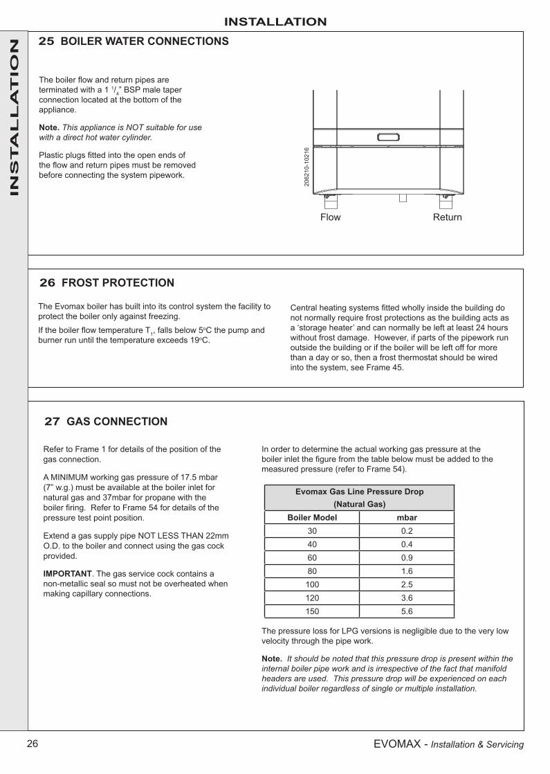
25 BOILER WATER CONNECTIONS
The boiler flow and return pipes are terminated with a 1 1/4” BSP male taper connection located at the bottom of the appliance.
Note. This appliance is NOT suitable for use with a direct hot water cylinder.
Plastic plugs fitted into the open ends of the flow and return pipes must be removed before connecting the system pipework.
26 FROST PROTECTION
The Evomax boiler has built into its control system the facility to protect the boiler only against freezing.
If the boiler flow temperature T1, falls below 5oC the pump and burner run until the temperature exceeds 19oC.
Central heating systems fitted wholly inside the building do not normally require frost protections as the building acts as a ‘storage heater’ and can normally be left at least 24 hours without frost damage. However, if parts of the pipework run outside the building or if the boiler will be left off for more than a day or so, then a frost thermostat should be wired into the system, see Frame 45.
INS
TA
LL
AT
ION
Flow Return
2062
10-1
0216
27 GAS CONNECTION
Refer to Frame 1 for details of the position of the gas connection.
A MINIMUM working gas pressure of 17.5 mbar (7” w.g.) must be available at the boiler inlet for natural gas and 37mbar for propane with the boiler firing. Refer to Frame 54 for details of the pressure test point position.
Extend a gas supply pipe NOT LESS THAN 22mm O.D. to the boiler and connect using the gas cock provided.
IMPORTANT. The gas service cock contains a non-metallic seal so must not be overheated when making capillary connections.
The pressure loss for LPG versions is negligible due to the very low velocity through the pipe work.
Note. It should be noted that this pressure drop is present within the internal boiler pipe work and is irrespective of the fact that manifold headers are used. This pressure drop will be experienced on each individual boiler regardless of single or multiple installation.
In order to determine the actual working gas pressure at the boiler inlet the figure from the table below must be added to the measured pressure (refer to Frame 54).
Evomax Gas Line Pressure Drop(Natural Gas)
Boiler Model mbar30 0.240 0.460 0.980 1.6100 2.5120 3.6150 5.6

27EVOMAX - Installation & Servicing
INSTALLATION
INS
TA
LL
AT
ION
External wiring MUST be in accordance with the current I.E.E. (BS7671) Wiring Regulations. For Ireland reference should be made to the current ETCI rules for electrical installations.The wiring diagrams illustrated in Frames 41-44 cover the systems most likely to be used with this appliance.For wiring external controls to the boiler, reference should be made to the systems wiring diagram supplied by the relevant manufacturer in conjunction with the connection diagram shown in Frame 30.Difficulty in wiring should not arise, providing the following directions are observed:1. The appliance must be wired with a permanent live supply.
External controls should NOT be wired in series with this mains input. Controlling the mains input in this way will prevent the pump over-run sequence and may cause damage to the heat exchanger.
2. 230V AC output is provided and must be used for the system pump and optionally for a DHW pump or valve, programmer and thermostats. Care must be taken to ensure that the earth conductor is longer than the current carrying conductors for reasons given in Frame 28.
29 EXTERNAL WIRING
3. Input terminals are available for connecting a variety of system controls for heating demand, and optionally for DHW demand.
Heating demand can be controlled by: • 230V programmer and/or room thermostat • programmable room thermostat kit • Modulating sequencer kit • a bms • outside temperature sensor DHW demand can be controlled by: • 230V programmer and/or cylinder thermostat • tank sensor kit
The electrical supply and their inputs onto the boiler can be seen in Frame 30.
4. An optional outside temperature sensor may be fitted for outside weather compensation. See Frame 30 for connection details.
Warning. This appliance MUST be efficiently earthed.
A mains supply of 230V 50Hz is required. The supply wiring MUST be suitable for mains voltage. Wiring should be 3 core PVC insulated cable NOT LESS than 0.75mm2 (24 x 0.2 mm) and to BS. 6500, Table 16. The fuse rating should be 4A.
Wiring external to the boiler MUST be in accordance with the current I.E.E. (BS7671) Wiring Regulations and any local regulations. For Ireland reference should be made to the current ETCI rules for electrical installations.
Connection should be made in a way that allows complete isolation of the electrical supply - such as a double pole
28 ELECTRICAL CONNECTIONS
switch, having a 3mm (1/8”) contact separation in both poles, or a plug and unswitched socket serving only the boiler and system controls. The means of isolation must be accessible to the user after installation.
When making mains electrical connections to the boiler it is important that the wires are prepared in such a way that the earth conductor is longer than the current carrying conductors, such that if the cord anchorage should slip the current carrying conductors become taut before the earthing conductor.
4 self adhesive cable clips are provided to aid routing of the wiring across the bottom panel of the boiler.

28 EVOMAX - Installation & Servicing
INSTALLATION
30 INSTALLER CONNECTIONS
INS
TA
LL
AT
ION
Per
man
ent
230V
acM
ains
Sup
ply
Opt
iona
l23
0Vac
Cal
l for
CH
Opt
iona
l23
0Vac
Cal
l for
HW
Opt
iona
l23
0Vac
DH
WP
ump
orD
iver
ter
Valv
eO
utpu
t
Opt
iona
l23
0Vac
CH
or
Sys
tem
Pum
pO
utpu
t
Opt
iona
l 5V
Ope
nThe
rmIn
put
Opt
iona
l 5
V O
utsi
deS
enso
rIn
put
Opt
iona
l 5V
DH
W T
ank
Sen
sor
Inpu
t
Opt
iona
l0-
10V
Inpu
t
206210-10228
1.
If a
Pum
p is
to b
e ru
n fro
m th
e bo
iler a
nd th
e el
ectri
cal c
urre
nt d
raw
is 1
.3A
indu
ctiv
e or
less
then
the
pum
p ca
n be
con
nect
ed d
irect
ly in
to th
e C
H P
ump
or D
HW
Pum
p co
nnec
tions
,
as a
ppro
pria
te (e
.g. G
rund
fos
40/6
0 U
PS
is s
atis
fact
ory)
. If
the
curr
ent d
raw
is m
ore
than
this
(eg
a G
rund
fos
40/1
20 U
PS
) the
n an
ext
erna
l rel
ay s
houl
d be
ope
rate
d by
the
C
H P
ump
or D
HW
Pum
p co
nnec
tions
, with
the
exte
rnal
rela
y th
en p
ower
ing
the
pum
p.2.
Th
e Lo
ckou
t Vol
t Fre
e R
elay
con
tact
s w
ill c
lose
4 m
inut
es a
fter a
Fau
lt oc
curs
.3.
Th
e B
urne
r On
Volt
Free
Rel
ay c
onta
cts
will
clo
se w
hen
the
Bur
ner i
s on
.4.
O
nly
Idea
l Out
side
Sen
sor a
nd D
HW
Tan
k S
enso
r kits
sho
uld
be c
onne
cted
to th
e bo
iler.
5.
The
Ext
erna
l Int
erlo
ck a
nd In
terlo
ck R
elay
Con
tact
s co
nnec
tions
are
onl
y us
ed in
con
junc
tion
with
the
Ext
erna
l Int
erlo
ck K
it.6.
Th
e R
ectif
ier c
onne
ctio
ns m
ust n
ot b
e us
ed (o
nly
used
in th
e ex
istin
g in
tern
al b
oile
r wiri
ng).
7.
The
eBus
con
nect
ions
are
not
for u
se.

29EVOMAX - Installation & Servicing
INSTALLATION
INS
TA
LL
AT
ION31 INTERNAL WIRING
g/y
g/y
1 X1A
X1B
X1D
X2A
X2B
X3
X7A
X7B
X6
X8
21
23
12
31
23
41
23
41
23
54
12
31
2
X4
32
14
12
X7C
12
12
34
56
12
34
56
78
910
11
Fan
Flow
Ther
mis
tor
Ret
urn
Ther
mis
tor
Flam
eS
enso
rE
lect
rode
Spa
rkE
lect
rode
Spa
rkG
ener
ator
PCB
Gas
Valv
e
Wat
erP
ress
ure
Sw
itch
Dia
gnos
ticC
onne
ctio
n
Cha
ssis
Ear
th
wbk
bkbk
bk
brb
bb
bb
br
orr
bkbk
bkbk
bkbk
bkbk
bkpk
oror
bky
yb
rpk
gry
pky
g/y
g/y
g/y
g/y
g/y
g/y
g/y
br br
g/y
brbr
brbr
brbr
rbk
LEG
END
b - b
lue
bk -
blac
kbr
- br
own
r - re
dpk
- pi
nk
y - y
ello
ww
- w
hite
y/g
- yel
low
/gre
engr
y - g
rey
or -
oran
gev
- vio
let
br b bbr

30 EVOMAX - Installation & Servicing
INSTALLATION
32 BASIC CONTROLS DISPLAY
Mains OnWhen the mains to the boiler is switched on a screen similar to the following will be displayedThe designation at the end of the bottom line indicates whether the boiler is suitable for Natural Gas or LPG.
Initialising Please WaitU/I PCB 330.E18Pri’ PCB 00.54 Nat Gas
Standby ModeFor Central Heating select Winter ModeFor Hot Water select Summer or Winter
Ideal
Standby ModeIf the boiler has been switched to Standby Mode the following screen will be displayedNo Boiler operation will take place with this setting. See Frame 34 to change to Summer or Winter setting
Summer ModeFor Central Heating select Winter ModeNo Hot Water DemandSwitched Live Off
Summer ModeIf the boiler has been switched to Summer Mode a screen similar to the following will be displayed (line 5 may vary depending on setup)Domestic Hot Water operation will take place with this setting but Central Heating will not.See Frame 34 to enable Central Heating by changing to Winter setting
EVOMAX USER INTERFACE
continued . . . . . . . .
Winter ModeNo Central Heating DemandNo Hot Water DemandSwitched Live Off
Winter ModeIf there is no current Heat Demand a screen similar to the following will be displayed (line 5 may vary depending on setup)Line 5 indicates “Switched Live” or “OpenTherm” or “0-10V” depending on which controls are connected to the boiler
Hot WaterDHW Switched Live OnBurner OnDHW ThermostatFlow Temp 80°C
Domestic Hot Water Mode (DHW Thermostat)If there is an ongoing Domestic Hot Water Demand using a DHW Thermostat, screens similar to the following will be displayedLine 2 indicates whether Switched Live or OpenTherm is controlling the boilerLine 3 indicates the current operating State (Pre-Purge or Ignition or Burner On or Pump Overrun)Burner Power and Flow Temperature will vary as the boiler operates
Hot WaterBurner Power 100%Burner OnDHW ThermostatFlow Temp 80°C
Hot WaterOpenTherm ModeBurner OnDHW Setpoint 65°CHot Water Temp’ 65°C
Domestic Hot Water Mode (DHW Thermistor)If there is an ongoing Domestic Hot Water Demand using a DHW Thermistor, screens similar to the following will be displayedLine 2 indicates whether Switched Live or OpenTherm is controlling the boilerLine 3 indicates the current operating State (Pre-Purge or Ignition or Burner On or Pump Overrun)Burner Power and Hot Water Temp’ will vary as the boiler operatesSee Frame 34 for adjusting DHW SetpointSee Frame 39 for configuring the boiler to use a DHW Thermistor
Hot WaterBurner Power 100%Burner OnDHW Setpoint 65°CHot Water Temp’ 65°C
INS
TA
LL
AT
ION

31EVOMAX - Installation & Servicing
INSTALLATION
33 BASIC CONTROLS DISPLAY CONTINUED......
continued . . . . . . . .
INS
TA
LL
AT
ION
Central HeatingCH Switched Live OnBurner OnFlow Setpoint 80°CFlow Temp 80°C
Central Heating ModeIf there is an ongoing Central Heating Demand screens similar to the following will be displayedLine 2 indicates whether Switched Live or OpenTherm is controlling the boilerLine 3 indicates the current operating State (Pre-Purge or Ignition or Burner On or Pump Overrun)Outside temperature will only be shown if an outside sensor is connected to the boilerBurner Power and Flow Temp will vary as the boiler operatesSee Frame 38 for adjusting Flow Setpoint
Central HeatingBurner Power 100%Outside Temp’ 10°CFlow Setpoint 80°CFlow Temp 80°C
Boiler Frost Protection ModeIf the boiler flow temperature drops below 5°C screens similar to the following will be displayedLine 3 indicates the current operating State (Pre-Purge or Ignition or Burner On or Pump Overrun)Outside temperature will only be shown if an outside sensor is connected to the boilerBurner Power and Flow Temp will vary as the boiler operates
Boiler Frost ProtectBurner Power 100%Outside Temp’ 10°CFrost Setpoint 5°CFlow Temp 80°C
Boiler Frost ProtectBurner Power 100%Burner OnFrost Setpoint 5°CFlow Temp 80°C
System Frost ProtectFlow Temp 80°CBurner OnFrost Setpoint -10°COutside Temp’ 10°C
System Frost Protection ModeIf an Outside Sensor is fitted and the Outside Temperature drops below the system frost protection temperture setpoint a screen similar to the following will be displayedLine 3 indicates the current operating State (Pre-Purge or Ignition or Burner On or Pump Overrun)Flow Temperature and Outside Temperature will vary as the boiler operatesSee Frame 38 for adjusting the system frost protection temperature setpoint.
Cylinder Frost ProtectBurner Power 100%Outside Temp’ 10°CFrost Setpoint 5°CHot Water Temp’ 4°C
Cylinder Frost Protection ModeIf a Domestic Hot Water Thermistor is connected to the boiler and the DHW temperature drops below 5C a screen similar to the following will be displayedLine 3 indicates the current operating State (Pre-Purge or Ignition or Burner On or Pump Overrun)Burner Power, Hot Water Temp’ and Outside Temp’ will vary as the boiler operatesOutside temperature will only be shown if an outside sensor is connected to the boiler
Cylinder Frost ProtectBurner Power 100%Burner OnFrost Setpoint 5°CHot Water Temp’ 4°C
0-10V OperationBurner Power 100%Burner OnBurner Setpoint Target 100%Flow Temp 80°C
0-10V Capacity Operating ModeIf 0-10V Capacity operation is ongoing screens similar to the following will be displayedLine 3 indicates the current operating State (Pre-Purge or Ignition or Burner On or Pump Overrun)Flow Temp’ and Burner Power will vary as the boiler operates0-10V Input and Burner Setpoint Target will vary as the external Building Management System controls themSee Frame 36 for configuring the boiler for 0-10V Capacity Operation
0-10V Operation0-10V Input = 10.0VBurner OnBurner Setpoint Target 100%Flow Temp 80°C
0-10V OperationBurner Power 100%Burner OnFlow Setpoint 80°CFlow Temp 80°C
0-10V Temperature Operating ModeIf 0-10V Temperature operation is ongoing screens similar to the following will be displayedLine 3 indicates the current operating State (Pre-Purge or Ignition or Burner On or Pump Overrun)Flow Temp’ and Burner Power will vary as the boiler operates0-10V Input and Flow Setpoint will vary as the external Building Management System controls them.See Frame 36 for configuring the boiler for 0-10V Temperature Operation.
0-10V Operation0-10V Input = 10.0VBurner OnFlow Setpoint 80°CFlow Temp 80°C

32 EVOMAX - Installation & Servicing
INSTALLATIONIN
STA
LL
AT
ION 34 EVOMAX USER INTERFACE - BASIC OPERATING INSTRUCTIONS
Ideal Evomax 80kW
Normal OperationSet Flow Temp’Set DHW Temp’
SETTING FLOW TEMPERATURE
Ideal Evomax 80kWNormal OperationSet Flow Temp’Set DHW Temp’Set Off/Sum/Win
Rotate the KNOB clockwise until a screen similar to the following is displayed
Set Flow Temp’
80°C
Press SELECT and a screen similar to the following will be displayed
Press + and - to change to the required setting and then press ENTER to storeRotate the KNOB anti-clockwise until Normal Operation is highlighted again and press SELECT to return to normal operation
continued . . . . . . . .
Press SELECT and a screen similar to the following will be displayedThe kW output number in the 1st line will vary depending the maximum output of the boiler
Note that DHW Temperature can only be set if a DHW Thermistor has been connected to the boiler and the boiler configured for its use. Without a DHW thermistor the flow temperature for the DHW switched live input will be controlled to the DHW Temperature Setpoint +4ºC.Press SELECT and a screen similar to the following will be displayedThe kW output number in the 1st line will vary depending the maximum output of the boiler
Ideal Evomax 80kW
Normal OperationSet Flow Temp’Set DHW Temp’
Ideal Evomax 80kWSet Flow Temp’Set DHW Temp’Set Off/Sum/WinOut’ Sensor Slope
Rotate the KNOB clockwise until a screen similar to the following is displayed
Set DHW Temp’
65°C
Press SELECT and a screen similar to the following will be displayed
SETTING DOMESTIC HOT WATER TEMPERATURE
Press + and - to change to the required setting and then press ENTER to storeRotate the KNOB anti-clockwise until Normal Operation is highlighted again and press SELECT to return to normal operation
Ideal Evomax 80kW
Normal OperationSet Flow Temp’Set DHW Temp’
Press SELECT and a screen similar to the following will be displayedThe kW output number in the 1st line will vary depending the maximum output of the boiler
Ideal Evomax 80kWSet DHW Temp’Set Off/Sum/WinOut’ Sensor SlopeNormal Operation
Rotate KNOB clockwise until a screen similar to following is displayed
Set Off/Sum/WinStandbySummerWinterPress - for more
Press SELECT and a screen similar to the following will be displayed
Press + and - to change to required setting, press ENTER to storeRotate the KNOB anti-clockwise until Normal Operation is highlighted again and press SELECT to return to normal operation
SETTING SUMMER, WINTER AND STANDBY OPERATIONNote that Standby Mode will disable Domestic Hot Water and Central Heating, Summer Mode will disable Central Heating
SETTING THE OUTSIDE SENSOR SLOPENote that an Outside Sensor must be fitted to the boiler for this feature to be active (this will be detected automatically)Press SELECT and a screen similar to the following will be displayedThe kW output number in the 1st line will vary depending on the maximum output of the boiler
Ideal Evomax 80kW Normal OperationSet Flow Temp’Set DHW Temp’
Rotate KNOB clockwise until a screen similar to following is displayedIdeal Evomax 80kWSet Off/Sum/WinOut’ Sensor SlopeState of InputsState of Outputs
Press SELECT and a screen similar to the following will be displayed
Out’ Sensor Slope
1.5
Note that a higher number gives a higher room temperature and a lower number gives a lower room temperaturePress + and - to change to required setting, press ENTER to storeRotate the KNOB anti-clockwise until Normal Operation is highlighted again and press SELECT to return to normal operation

33EVOMAX - Installation & Servicing
INSTALLATION
INS
TA
LL
AT
ION35 EVOMAX USER INTERFACE - BASIC OPERATING INSTRUCTIONS CONTINUED...
continued . . . . . . . .
Ideal Evomax 80kW
Normal OperationSet Flow Temp’Set DHW Temp’
VIEWING THE STATE OF THE BOILER INPUTS
Press SELECT and a screen similar to the following will be displayedThe kW output number in the 1st line will vary depending the maximum output of the boiler
Ideal Evomax 80kWOut’ Sensor SlopeState of InputsState of OutputsFault History
Rotate KNOB clockwise until a screen similar to the following is displayed
State of InputsFlow Temp’ 80ºCReturn Temp’ 60ºCFlue Temperature 70ºCPress - for more
Press SELECT and a screen similar to the following will be displayed
The state of the iniputs will vary as the boiler operatesPress SELECT to exit this optionRotate the KNOB anti-clockwise until Normal Operation is highlighted again and press SELECT to return to normal operation
Press SELECT and a screen similar to the following will be displayedThe kW output number in the 1st line will vary depending the maximum output of the boiler
Ideal Evomax 80kW Normal OperationSet Flow Temp’Set DHW Temp’
Rotate KNOB clockwise until a screen similar to the following is displayedIdeal Evomax 80kWState of InputsState of OutputsFault HistoryShow Hours Run
VIEWING THE STATE OF THE BOILER OUTPUTS
Press SELECT and a screen similar to the following will be displayed
State of OutputsBoiler Pump OnDHW Pump/Valve OffFan 3000rpmPress - for more
The state of the outputs will vary as the boiler operatesPress SELECT to exit this optionRotate the KNOB anti-clockwise until Normal Operation is highlighted again and press SELECT to return to normal operation
VIEWING THE FAULT HISTORY OF THE BOILER
Press SELECT and a screen similar to the following will be displayedThe kW output number in the 1st line will vary depending the maximum output of the boiler
Ideal Evomax 80kW
Normal OperationSet flow Temp’Set DHW Temp’
Rotate KNOB clockwise until a screen similar to the following is displayed
Ideal Evomax 80kWState of OutputsFault HistoryShow Hours RunNormal Operation
Press SELECT and a screen similar to the following will be displayed
Fault History: Max 10Fault 1 [Latest]Ignition Lockout [16]23 days agoPress - for more
The Fault History will vary depending on the operation of the boilerPress SELECT to exit this optionRotate the KNOB anti-clockwise until Normal Operation is highlighted again and press SELECT to return to normal operation
VIEWING THE BOILER HOURS RUN
Press SELECT and a screen similar to the following will be displayedThe kW output number in the 1st line will vary depending the maximum output of the boiler
Ideal Evomax 80kW Normal OperationSet Flow Temp’Set DHW Temp’
Rotate KNOB clockwise until a screen similar to following is displayedIdeal Evomax 80kWFault HistoryShow Hours RunNormal Operation
Press SELECT and a screen similar to the following will be displayedShow Hours Run Total Hours 20 hFlame On 10 h
The times will vary depending on the operation of the boilerPress SELECT to exit this optionRotate the KNOB anti-clockwise until Normal Operation is highlighted again and press SELECT to return to normal operation

34 EVOMAX - Installation & Servicing
INSTALLATIONIN
STA
LL
AT
ION 36 EVOMAX USER INTERFACE - ADVANCED OPERATING INSTRUCTIONS
SETTING TO 0-10V
Press SELECT and then hold + and - down together for more than 5s, the following screen will be displayed
Installer Mode Normal OperationSet Flow Temp’Set DHW Temp’
Rotate the KNOB clockwise until the following screen is displayed
Installer ModeShow Hours RunSet to 0-10V InputSet Night SetbackDHW Pump / Valve
Press SELECT and the following screen will be displayed
Set to 0-10V Input
0-10V Off0-10V Capacity0-10V Temperature
Press + and - to change to the required setting and then press ENTER to storeRotate the KNOB anti-clockwise until Normal Operation is highlighted again and press SELECT to return to normal operation
10000
9000
8000
7000
6000
5000
4000
3000
2000
1000
0
Min
imum
CH
Fan
Spee
d
Max
imum
CH
Fan
Spee
d
Heat
requ
est i
s O
FF
Capacity Control
0-10V Capacity Control is governed by the following relationship
100
90
80
70
60
50
40
30
20
10
0
Max
. flo
w te
mpe
ratu
re s
et p
oint
Heat
requ
est O
FFBo
iler f
rost
pro
tect
ion
set p
oint
Max
. Flo
w Te
mpe
ratu
re S
et P
oint
Temperature Control
Tem
pera
ture
[ºC
]
0-10V Temperature Control is governed by the following relationship
continued . . . . . . . .

35EVOMAX - Installation & Servicing
INSTALLATION
INS
TA
LL
AT
ION37 EVOMAX USER INTERFACE - ADVANCED OPERATING INSTRUCTIONS CONTINUED....
ENABLING VALVE POWER OPEN/VALVE POWER CLOSED/SHUNT PUMP
The boiler default setting is the CH Pump output will only be On for a CH Demand and the DHW Pump output will only be on for a DHW Demand.This can be changed so that the CH Pump output controls the system pump and the DHW Pump output operates a Valve (power open or power shut)This can also be changed so that the CH Pump output controls a system pump and the DHW Pump output controls a shunt pumpPress SELECT and then hold + and - down together for more than 5s, the following screen will be displayed
Installer Mode Normal OperationSet Flow Temp’Set DHW Temp’
Rotate the KNOB clockwise until the following screen is displayedInstaller ModeSet Night SetbackDHW Pump/ValveSet BoosterCH/DHW Priority
Press SELECT and the following screen will be displayed
DHW Pump/Valve
PumpValve Power OpenPress - for more
Press + and - to change to the required setting and then press ENTER to storeRotate the KNOB anti-clockwise until Normal Operation is highlighted again and press SELECT to return to normal operation
continued . . . . . . . .
ENABLING NIGHT SETBACKNote- Night Setback is only operational if Outside Sensor has been connectedWhen Night Setback is enabled the boiler will run at the normal flow temp. during CH Demand and reduced temperature when for no demandPress SELECT and then hold + and - down together for more than 5s, the following screen will be displayed
Installer Mode Normal OperationSet Flow Temp’Set DHW Temp’
Rotate the KNOB clockwise until the following screen is displayedInstaller ModeSet to 0-10V InputSet Night SetbackDHW Pump / ValveSet Booster
Press SELECT and the following screen will be displayedSet Night Setback OnOff
Press + and - to change to required setting and then press ENTER to storeRotate the KNOB anti-clockwise until Normal Operation is highlighted again and press SELECT to return to normal operation
Installer Mode Normal OperationSet Flow Temp’Set DHW Temp’
Note- Booster Function is only operational if Outside Sensor has been connectedIf Booster function is enabled and CH Demand is ongoing for more than 10 minutes then the Flow Temp. target is increased by 10°CWhen the Burner switches off the temperature is resetPress SELECT and then hold + and - down together for more than 5s, the following screen will be displayed
Rotate the KNOB clockwise until the following screen is displayedInstaller ModeDHW Pump / ValveSet BoosterCH/DHW PrioritySet Max Flow Temp’
Press SELECT and the following screen will be displayed
Set Booster OnOff
Press + and - to change to required setting then press ENTER to storeRotate the KNOB anti-clockwise until Normal Operation is highlighted again and press SELECT to return to normal operation
CHANGING 2ND SWITCHED LIVE INPUT BETWEEN DHW & CH
Installer Mode Normal OperationSet Stat 1 TempSet Stat 2 Temp
To change the 2nd switched live input from DHW operation (factory default) to CH operation, press SELECT and then hold + and - down together for more than 5s and the following screen will be displayed:
Rotate the 1st stat clockwise until the following screen is displayed
Installer ModeSet Booster2nd SL DHW / CHCH / DHW PrioritySet Max Flow Temp’
Press SELECT and the following screen will be displayed2nd SL DHW / CH DHWCH2, Priority = SL2CH2, Priority = SL1
Press + and - to change to the required setting and then press ENTER to store.Rotate the KNOB clockwise until Normal Operation is highlighted again and press SELECT to return to normal operation

36 EVOMAX - Installation & Servicing
INSTALLATIONIN
STA
LL
AT
ION
CHANGING THE MAXIMUM FLOW TEMPERATURE SETPOINT
Installer Mode Normal OperationSet Flow Temp’Set DHW Temp’
Boiler default setting is that maximum flow temperature setpoint is 82°CThis feature limits the maximum flow temperature that can be set in the Basic Operating ModePress SELECT and then hold + and - down together for more than 5s, the following screen will be displayed
Rotate the KNOB clockwise until the following screen is displayedInstaller ModeCH/DHW PrioritySet Max Flow Temp’Set Min Flow Temp’Sys Frost Protect
Press SELECT and the following screen will be displayedSet Max Flow Temp’ 80°C
Press + and - to change to the required setting and then press ENTER to storeRotate the KNOB clockwise until Normal Operation is highlighted again and press SELECT to return to normal operation
CHANGING THE MINIMUM FLOW TEMPERATURE SETPOINT
Installer Mode Normal OperationSet Flow Temp’Set DHW Temp’
Boiler default setting is that minimum flow temperature setpoint is 30°CThis feature limits the minimum flow temperature that can be set in the Basic Operating ModePress SELECT and then hold + and - down together for more than 5s, the following screen will be displayed
Rotate the KNOB clockwise until the following screen is displayed
Installer ModeSet Max Flow Temp’Set Min Flow Temp’Sys Frost ProtectSoft Start Time
Press SELECT and the following screen will be displayedSet Max Flow Temp’ 30°C
Press + and - to change to the required setting and then press ENTER to storeRotate the KNOB clockwise until Normal Operation is highlighted again and press SELECT to return to normal operation
CHANGING THE SYSTEM FROST PROTECTION TEMP. SETPOINT
Installer Mode Normal OperationSet Flow Temp’Set DHW Temp’
Note that System Frost Protection Function is only operational if an Outside Sensor has been connectedThe CH pump is switched on if the Outside Temp. is less than the System Frost Protection Temp.The CH pump is switched off if the Outside Temp. is more than the System Frost Protection Temp. +5°CThe boiler default setting is the system frost protection temp. setpoint is -10°CPress SELECT and then hold + and - down together for more than 5s, the following screen will be displayed
Rotate the KNOB clockwise until the following screen is displayedInstaller ModeSet Min Flow Temp’Sys Frost ProtectSoft Start TimeO/S Room Temp’
Press SELECT and the following screen will be displayedSys Frost Protect -10°C
Press + and - to change to required setting, press ENTER to storeRotate the KNOB clockwise until Normal Operation is highlighted again and press SELECT to return to normal operation
continued . . . . . . . .
38 EVOMAX USER INTERFACE - ADVANCED OPERATING INSTRUCTIONS
CHANGING CH / DHW PRIORITY
Installer Mode Normal OperationSet Flow Temp’Set DHW Temp’
The boiler default setting is DHW always has priority ahead of CHIt is possible to change this so CH always has priority ahead of DHW or the boiler alternates between DHW and CH every 10 minsPress SELECT and then hold + and - down together for more than 5s, the following screen will be displayed
Rotate the KNOB clockwise until the following screen is displayedInstaller ModeSet BoosterCH/DHW PrioritySet Max Flow Temp’Set Min Flow Temp’
Press SELECT and the following screen will be displayedCH/DHW Priority Priority = DHWPriority = CHPriority = Equal
Press + and - to change to the required setting and then press ENTER to storeRotate the KNOB clockwise until Normal Operation is highlighted again and press SELECT to return to normal operation
Note: if this menu option is not displayed then the “2nd sL DHW/CH” menu option has been set for CH. CH Priority can be set from the “2nd sL DHW/CH” menu option or the 2nd sL can be reconfigured for DHW operation.

37EVOMAX - Installation & Servicing
INSTALLATION
INS
TA
LL
AT
ION
CHANGING THE SOFT START TIME
Installer Mode Normal OperationSet Flow Temp’Set DHW Temp’
The Soft Start Time is the time for which the boiler will run at the ignition rate after a flame is detectedThis feature helps make the boiler fully compatible with the CH/DHW system. The default Soft Start time is 5sCare should be taken in adjusting this feature as system noise and/or boiler lockout could occurPress SELECT and then hold + and - down together for more than 5s, the following screen will be displayed
Rotate the KNOB clockwise until the following screen is displayedInstaller ModeSys Frost ProtectSoft Start TimeO/S Room Temp’DHW Sensor
Press SELECT and the following screen will be displayedSoft Start Time 5s
Press + and - to change to required setting then press ENTER to storeRotate the KNOB clockwise until Normal Operation is highlighted again and press SELECT to return to normal operationNote that the minimum setpoint after adjustment is 60s
ENABLING THE DOMESTIC HOT WATER THERMISTOR
Installer Mode Normal OperationSet Flow Temp’Set DHW Temp’
The default is for a DHW Heat Demand to be indicated by a DHW Thermostat providing a 230V input to the DHW Switched LiveInstead a DHW Thermistor, available as a kit from Ideal, can be connected to the DHW Thermistor inputRotate the KNOB clockwise until the following screen is displayed
Rotate the KNOB clockwise until the following screen is displayedInstaller ModeO/S Room Temp’DHW SensorFactory SettingsAnti-Legion Temp’
Press SELECT and the following screen will be displayed
DHW SensorHeating OnlyDHW ThermistorDHW Switched Live
Press + and - to change to the required setting and then press ENTER to storeRotate the KNOB clockwise until Normal Operation is highlighted again and press SELECT to return to normal operation
continued . . . . . . . .
CHANGING THE NOMINAL ROOM TEMPERATURE ACHIEVED DURING OUTSIDE SENSOR OPERATION (O/S ROOM TEMP’)
Installer Mode Normal OperationSet Flow Temp’Set DHW Temp’
Note that the O/S Room Temp’ Function is only operational if an Outside Sensor has been connectedThe O/S Room Temp’ is the notional room temperature that the boiler will try to achieve under Weather Compensation operationThe default O/S Room Temp’ is 20°CPress SELECT and then hold + and - down together for more than 5s, the following screen will be displayed
Rotate the KNOB clockwise until the following screen is displayedInstaller ModeSoft Start TimeO/S Room Temp’DHW SensorFactory Settings
Press SELECT and the following screen will be displayedO/S Room Temp’ 20ºC
Press + and - to change to required setting, press ENTER to storeRotate the KNOB clockwise until Normal Operation is highlighted again and press SELECT to return to normal operation
39 EVOMAX USER INTERFACE - ADVANCED OPERATING INSTRUCTIONS CONTINUED....

38
INSTALLATION
EVOMAX - Installation & Servicing
INS
TA
LL
AT
ION
INS
TA
LL
AT
ION
INS
TA
LL
AT
ION
DISABLING THE ANTI-LEGIONELLA FUNCTION
Installer Mode Normal OperationSet Flow Temp’Set DHW Temp’
Note that the Anti-Legionella Temperature Function is only operational if a Domestic Hot Water Thermistor has been connected.Care should be taken in disabling this function as an unsafe condition could result.Press SELECT and then hold + and - down together for more than 5s, the following screen will be displayed
Rotate the KNOB clockwise until the following screen is displayed
Installer ModeAnti-Legion Temp’Anti-Legion EnableBUS AddressFlame/LPG Relay
Press SELECT and the following screen will be displayedAnti-Legion Enable OnOff
Press + and - to change to required setting then press ENTER to storeRotate the KNOB clockwise until Normal Operation is highlighted again and press SELECT to return to normal operation
CHANGING THE VOLT FREE BURNER ON RELAY TO OPERATE AS AN LPG RELAY FOR BELOW GROUND LEVEL LPG APPLICATIONS
Installer Mode Normal OperationSet Flow Temp’Set DHW Temp’
If LPG is to be used in an application below ground level then an additional valve is required to control the LPG input to the boilerThis valve should be wired from the Volt Free Burner on Relay and enabled as followsPress SELECT and then hold + and - down together for more than 5s, the following screen will be displayed
Rotate the KNOB clockwise until the following screen is displayed
Installer ModeBUS AddressFlame/LPG RelayNormal Operation
Press SELECT and the following screen will be displayed
Flame/LPG Relay Flame OnLPG Gas Valve
Press + and - to change to the required setting and then press ENTER to storeRotate the KNOB clockwise until Normal Operation is highlighted again and press SELECT to return to normal operation
40 EVOMAX USER INTERFACE - ADVANCED OPERATING INSTRUCTIONS CONTINUED....
REVERTING TO FACTORY SETTINGS
Installer Mode Normal OperationSet Flow Temp’Set DHW Temp’
Press SELECT, hold + and - together for more than 5s, the following screen will be displayed
Rotate the KNOB clockwise until the following screen is displayedInstaller ModeDHW SensorFactory SettingsAnti-Legion Temp’Anti-Legion Enable
Press SELECT and the following screen will be displayedFactory Settings Reset?
Press ENTER and a screen similar to the following will be displayedFactory SettingsAre you sure?Press Enter to ResetPress Select not to Reset
Press ENTER and a screen similar to the following will be displayedFactory Settings Reset?
Press Select then Rotate the KNOB clockwise until Normal Operation is highlighted again and press SELECT to return to normal operation
CHANGING THE ANTI-LEGIONELLA TEMPERATURE
Installer Mode Normal OperationSet Flow Temp’Set DHW Temp’
Note Anti-Legionella Temp. Function is only operational if a DHW Thermistor has been connectedCare should be taken reducing this temp. as unsafe condition could resultPress SELECT and then hold + and - down together for more than 5s, the following screen will be displayed
Rotate the KNOB clockwise until the following screen is displayedInstaller ModeFactory SettingsAnti-Legion Temp’Anti-Legion EnableBUS Address
Press SELECT and the following screen will be displayedAnti-Legion Temp’ 70°C
Press + and - to change to required setting, press ENTER to storeRotate the KNOB clockwise until Normal Operation is highlighted again and press SELECT to return to normal operation

39EVOMAX - Installation & Servicing
INSTALLATION
INS
TA
LL
AT
ION41 EVOMAX WITH S PLAN SYSTEM
Pump
Pump
Boiler
S PlanValve
L
Timer
FusedSpur
N
L NCH On
HW On
CHS PlanValve
HWS PlanValve
ECHOn
R/SOn
R/S
HWOn
HWOff
C/SOn
L N E
C/S
Note that the boiler can use an Outside Sensor, which is available from ideal as a Weather Compensation Kit. In this case the link from position 9 to position 10 in the installer terminal block should be removed and a wire added from position 10 to the DHW Call input on the boiler.
Note that a hydraulic bypass is required to allow pump overrun.
Note that a Frost Stat can be connected into CH call.
S Plan Valve
g
g
b
b
g/y
g/y
bro
obr
42 EVOMAX WITH Y PLAN SYSTEM
Pump
Boiler
Y PlanValve
L
Timer
FusedSpur
N
L NCH On
HW On
HW Off
Y PlanValve
ECHOn
R/SOn
R/S
HWOn
HWOff
C/SOn
L N E
C/S
206210-10232
Note that a Frost Stat can be connected into CH call.
Pump
g/yb
og
w

40 EVOMAX - Installation & Servicing
INSTALLATION
43 EVOMAX WITH BOILER CONTROL OF CH AND DHW PUMPS
Pump
W PlanValve
TimerL N
CH On
HW On
CHPump
Boiler
Diverter ValvePower Open
FusedSpur
L N E
C/S
R/S
206210-10234
Note 1. The boiler must be configured to control a Power Open Diverter Valve (the factory setting is for it to control CH and DHW Pumps. See page 34Note 2. The boiler can use an Outside Sensor, which is available from Ideal as a Weather Compensation Kit.Note 3. The boiler can use a Tank Sensor rather than a Cylinder Thermostat, which is available from Ideal as a kit.Note 4. A Frost Thermostat can be connected into CH Call
INS
TA
LL
AT
ION
44 EVOMAX WITH BOILER CONTROL OF PUMP AND DIVERTER VALVE
Pump
CHPump
TimerL N
CH On
HW On
Boiler
DHWPump
FusedSpur
L N E
C/S
R/S
206210-10233
Note 1. The boiler can use an Outside Sensor, which is available from Ideal as a Weather Compensation Kit.Note 2. The boiler can use a Tank Sensor rather than a Cylinder Thermostat, which is available from Ideal as a kit.Note 3. A hydraulic bypass is required to allow pump overrun.
Note 4. This system provides heating to one zone at a time. To heat more than one zone simultaneously use zone thermostats to energise individual zone valves with a call for heat applied to CH Call. The boiler will be limited to responding with a set flow temp (see page 31). The boiler default setting is for DHW priority.
Note 5. A Frost Thermostat can be connected into CH Call

41EVOMAX - Installation & Servicing
INSTALLATION
INS
TA
LL
AT
ION
2062
10-1
0235
Notes.1. The boiler will automatically configure itself to a Switched Live input.2. The Switched Live must be from the same phase as the boiler mains supply.3. A Frost Thermostat can be connected into the CH Call Input.
Pump
Boiler
FusedSpur
SwitchedLive
External Controls
L N E
45 EVOMAX WITH EXTERNAL CONTROLS VIA SWITCHED LIVE, 0-10V INPUT OR OPENTHERM
The boiler must be set fpr 0-10V input. (See Frame 40)
Boiler
Pump
FusedSpur
L N E
2062
10-1
0236
0-10VSource
The boiler will automatically configure itself to an Opentherm input.
Boiler
Pump
OpenTherm
ExternalControls
FusedSpur
L N E
2062
10-1
0236
EXTERNAL CONTROLSVIA OPENTHERM
EXTERNAL CONTROLSVIA 0-10V INPUT
EXTERNAL CONTROLSVIA SWITCHED LIVE
Note that the boiler requires a 4 minute pump overrun period.
The boiler warranty will be invalid if this is not provided.
It is recommended that the pump overrun functionality is achieved by connecting the pump to the boiler CH Pump connections (see diagram), although this functionality can be replicated with external controls (for example a Building Management System).
If the CH Pump connection is used and the electrical current draw is 1.3A inductive or less then the pump can be connected directly into the CH Pump connection (a Grundfos 40/50 UPS is OK).
If the current draw is more than this (eg a Grundfos 40/120 UPS) then an external relay should be operated by the CH Pump connection, with the external relay then powering the pump.

42 EVOMAX - Installation & Servicing
INSTALLATIONIN
STA
LL
AT
ION 46 EVOMAX WITH OPENTHERM 2 CHANNEL PROGRAMMABLE ROOM STAT
Pump
W PlanValve
Note 1. The OpenTherm 2 Channel Programamble Room thermostat is available from Ideal as a kit.Note 2. The Tank Temperature Sensor is available from ideal as a kit.Note 3. The boiler must be configured to control a Power Open diverter Valve (See page 34)
Boiler
Diverter ValvePower Open
DHWPump
Opentherm2 Channel
Prog. RoomStat
FusedSpur
L N E
206210-10238
Tank Sensor
47 COMMISSIONING AND TESTING
A. ELECTRICAL INSTALLATION
1. Checks to ensure electrical safety should be carried out by a competent person.
2. ALWAYS carry out the preliminary electrical system checks, i.e. earth continuity, polarity, resistance to earth and short circuit, using a suitable meter.
WARNING. Whilst effecting the required gas soundness test and purging air from the gas installation, open all windows and doors, extinguish naked lights and DO NOT SMOKE.
B. GAS INSTALLATION
1. The whole of the gas installation, including the meter, should be inspected and tested for soundness and then purged in accordance with the recommendations of the relevant standards listed on page 8, by the installer.
In IE refer to I.S.813:2002.

43EVOMAX - Installation & Servicing
INSTALLATION
INS
TA
LL
AT
ION48 INITIAL LIGHTING
OPERATING SEQUENCE
1. Check that the system has been filled and the boiler is not air locked - air in the boiler could damage the heat exchanger. For this reason the airvent located in the left top side must never be shut off.
2. Check that all the drain cocks are closed and any valves in the flow and return are open.
3. Check that the GAS SERVICE COCK IS ON.
4. Fill the condensate trap with water before putting the unit into operation (see Frame 58 for condensate trap removal).
5. Check the indication on the pressure gauge. If the pressure is less than 1 bar the installation should be filled up first (sealed system only).
6. Switch the electricity supply ON and check that all the external controls are calling for heat. Check boiler is set for winter operation - see Evomax user interface basic operating instructions.
7. The boiler will commence the ignition sequence. If after 5 attempts the boiler has failed to light then it will lock out. Press the reset button to restart the ignition sequence.
8. Operate the boiler for 10 minutes and check the gas rate (Table 1). You should be able to read at least 90% of the nominal.
Evomax ~ Flue CO2 % measurements (hot condition)
30 40 60 80 100 120 150 30P 40P 60P 80P
Max Rate 9.2% - 10.2% 10.9% - 11.9%
Min Rate 8.2% - 9.2% 9.7% - 10.7% 10.0% - 11.0%
Standby
yes
yes
yes
yes
no
no
no
no
no
noyes
yes
Heat demand on?
Temp. < setpoint?
Demandoff or Temp. >setpoint?
Heat Demand Off?
Fan off. Pump off
Flame detected?
Demand On& Temp. <Set point & Anti-cycle
done?
Fan On20s Fan Pre-purge
Pump On
Spark Generator OnGas Valve On
3s Ignition Period
Burner Output controlled relative toHeat Demand by varying Fan Speed
Burner On
Spark Generator Off1st Stabilisation Period
Gas Valve OffPump Overrun
Note. The fan runs for 4 mins after the burner
switches off
Standby

44 EVOMAX - Installation & Servicing
INSTALLATION
ROUTINE OPERATIONFull instructions covering routine lighting and operation of the boiler are given on the Lighting and Operation Instruction Label located on the inside of the lower controls door.
Draw the attention of the boiler owner or his representative to the Lighting and Operating Instruction Label. Give a practical demonstration of the lighting and shutting down of the boiler.
Describe the function of the boiler and system controls and show how they are adjusted and used.
Hand these Installation and Servicing Instructions, User’s Instructions and Log book to the customer and request him to keep them in a safe place for ready reference. For IE, it is necessary to complete a “Declaration of Conformity” to indicate compliance to the appropriate standard.
Make the following checks for correct operation.
1. The correct operation of ANY secondary system controls should be proved. Operate each control separately and check that the main burner or circulating pump, as the case may be, responds.
2. Water circulation system;
a. With the system HOT examine all water connections for soundness.
b. With the system still HOT, turn off the gas, water and electricity supplies to the boiler and drain down to complete the flushing process.
c. Refill and vent the system, clear all air locks and again check for water soundness.
d. Balance the system.
3. Check the condensate drain for leaks and check it is discharging correctly.
4. Finally set the controls to the User’s requirements.
Note. If an optional programmer kit is fitted then refer to the instructions supplied with the kit.
49 GENERAL CHECKS
50 HANDING OVER
IMPORTANT. Point out to the owner that the boiler must have regular maintenance and cleaning, at least annually, in order to ensure reliable and efficient operation. Regular attention will also prolong the life of the boiler and should preferably be performed at the end of the heating season.
After servicing, complete the service section of the log book and return to the owner or their representative.
Recommend that a contract for this work should be made with the regional gas authority or a Gas Safe Registered Engineer. In IE servicing work must be carried out by a competent person.
INS
TA
LL
AT
ION
51 SAFETYIt is the law that any service work must be carried out by a Gas Safe Registered Engineer. In IE service work must be carried out by a competent person.
WARNING. Always turn off the gas supply at the gas service cock, and switch off and disconnect the electricity supply to the appliance and any external controls before servicing or replacing components.
NOTE.When the burner switch is in the off position the boiler control module remains live.
IMPORTANT.
After completing the servicing or replacement of components always:
• Test for gas soundness.
• Check the water system is correctly filled and free of air. Air in the boiler could cause damage to the heat exchanger. For this reason the automatic air vent in the left top side must never be shut off.
• Check the jacket front panel is correctly fitted, ensuring that a good seal is made. Secure the controls fascia in place.
• With the system hot examine all water connections for soundness.
• Check the gas rate and measure the combustion CO/CO2 content. The CO/CO2 ratio of the flue gas should not be greater than 0.004 ratio & the CO should not exceed 350ppm. The CO2 should be as stated in Frame 48.
• Carry out functional checks as appropriate.

45EVOMAX - Installation & Servicing
SERVICING
52 SERVICING SCHEDULETo ensure the continued safe and efficient operation of the appliance it is recommended that it is checked at regular intervals and serviced as necessary. The frequency of servicing will depend upon the installation condition and usage but should be carried out at least annually.
Ideal Boilers does not accept any liability resulting from the use of unauthorised parts or the repair and servicing of appliances not carried out in accordance with the Company’s recommendations and specifications.
Note.
Some aluminium oxide build-up within the heat exchanger assembly is quite usual with this type of condensing boiler. Though removal and cleaning is recommended annually, the heat exchanger, sump and condensate trap must be inspected and cleaned after a maximum of 2 years operation.
1. Light the boiler and carry out function checks, noting any operational faults.
2. Run the boiler for 5 minutes and then check the gas consumption rate. Refer to procedure opposite on how to force the burner to maximum rate.
3. Optional test - Connect a suitable gas analyser to the sampling point fitted in the flue adapter. For correct boiler operation the CO/CO2 ratio of the flue gas should not be greater than 0.004 ratio and the CO2 values should match those in table 1. If this is the case and the gas input is at least 90% of the nominal, once compliance with the note above is ensured, then no further action need be taken. If not proceed to 4.
4. Remove and clean the burner. Refer to Frames 55 and 56.
5. Inspect the heat exchanger through the burner opening. If there are signs of aluminium oxide build up, spray water down the flueways. Refer to Frame 56.
6. Remove the sump cover and scrape out any deposits. Refer to Frame 57.
7. Remove the condensate trap and flush through with water. Refer to Frame 58.
8. Check that the flue terminal is unobstructed and that the flue system is sealed correctly.
9. After completion of servicing refer to Frame 51 for reference to final safety checks.
53 CASING REMOVALFront Panels1. Pull the two sides of the control casing door to open.
2. Remove the two screws retaining the front panel, lift the panel to remove.
3. Remove the two screws retaining the control panel and swing the panel down into the service position.
Side PanelsNote. Removal is not required for normal service.
1. Remove the two (or three) screws from the top and bottom of the side panels.
2. Re-assemble in reverse order.
2
3
SE
RV
ICIN
G
Ideal 80kW
Normal OperationSet Flow Temp’Set DHW Temp’
Ideal 80kWSet DHW Temp’Set Off/Sum/WinOut’ Sensor SlopeState of Inputs
Rotate KNOB clockwise until the following screen is displayed
Set Off/Sum/WinStandbySummerWinterPress - for more
Set Off/Sum/WinMinimumMaximum
Press - for more
Press SELECT and the following screen will be displayed
Press + and - until the followint screen is displayed.
Press ENTER and the boiler will go to Maximum Rate for 5 minutesOperation will be automatically reset at the end of 5 minutes
SETTING TO MAXIMUM OUTPUTEnsure that there is a current CH demand to the boiler (e.g. the CH Switched Live is on)Press SELECT and the following screen witll be displayed.The kW output number in the 1st line will vary depending on the maximum output of the boiler.

46 EVOMAX - Installation & Servicing
SERVICINGS
ER
VIC
ING
8
4
3
54 REMOVAL OF FAN AND GAS VALVE ASSEMBLY
1. Refer to Frame 51.2. Remove the upper front panel, Refer to Frame 53. 3. Remove the two screws retaining the flue tube to the
heat exchanger.4. Lift the lower section of flue upwards to disengage
from the sump then twist outwards and pull down to completely remove..
5. Disconnect condensate pipe from upper flue elbow.6. Remove the flue tube elbow fixing screws and remove
elbow by pulling downwards.
7. Disconnect the electrical connections from the gas valve/s.8. Disconnect the electrical connections from the fan.9. Undo the gas valve union nut/nuts and retain the fibre
washer/s.10. Remove the four nuts/washers (or screws depending upon
boiler size) retaining the fan assembly and remove the fan assembly.
11. Inspect & clean as necessary.12. Re-assemble in reverse order replacing all gaskets.
6
5
7
9
150 Model with Dual Gas Valves
Inlet Gas Pressure Test Point for 30, 40, 60 80 & 150 modelsFor 100 & 120 models the inlet gas pressure test point can be found on the inlet gas manifold
10

47EVOMAX - Installation & Servicing
SERVICING
SE
RV
ICIN
G
56 HEAT EXCHANGER INSPECTION / CLEANING
55 BURNER REMOVAL1. Refer to Frame 51.2. Remove the front panel (Refer to frame 53)3. Remove the fan and gas valve assembly (Refer to frame 54)4. Remove the six/eight extended nuts securing the burner to release
the burner body.5. Lift the burner body to remove it from the studs and lift the burner
out of its recess.6. The burner can now be cleaned on the back face only, the metal
fibre surface must not be touched. The burner must be replaced if it shows signs of damage.
7. After cleaning the burner replace it in the recess and check the burner body seal for signs of damage. If damage is apparent it must be replaced.
8. Reassemble in reverse order. The six (or eight) extended nuts should be fitted following a diagonal tightening sequence twice. The nuts should be secured firmly.
9. Check the operation of the boiler (Refer to Frame 51).
1. Refer to Frame 51.2. Remove the front panel (Refer to frame 53)3. Remove the fan and gas assembly (Refer to frame 54)4. Remove the burner (Refer to frame 55)5. Remove the ignition and detection electrodes (Refer to frame
62/63)6. Inspect the heat exchanger for signs of aluminium oxide
deposits. If necessary clean the heat exchanger by spraying water down the flue ways.
7. Reassemble in reverse order replacing all gaskets.8. Check the operation of the boiler (Refer to frame 51
4
57 REMOVAL OF SUMP COVER1. Refer to Frame 51.2. Remove the front panel (Refer to frame 53)3. Prepare boiler for possible water spillage during
the process.4. Remove the two screws from the helmholtz/clean-
out cover and pull away from the boiler.5. Scrape out any deposits.6. Reassemble in reverse order replacing all gaskets.
44
Models 30, 40, 150 Models 60, 80, 100 & 120
1. Refer to Frame 51.2. Unscrew the nut and disconnect the flexible
pipe.3. Unscrew the top nut and remove the
condensate trap.4. Remove the ball from the condensate trap and
flush out with water to remove any debris.5. Reassemble in reverse order.6. Check the operation of the boiler (Refer to
frame 51)
58 CONDENSATE TRAP
3
4
2

48 EVOMAX - Installation & Servicing
SERVICINGS
ER
VIC
ING
59 FAN REPLACEMENT1. Refer to Frame 51.2. Remove the upper front panel (Refer to frame 53).3. Remove the fan and gas assembly (Refer to frame 54).4. Remove the screws retaining the venturi to the fan (for
30, 40, 60, 80, 100 & 120 or mixing chambers (150 only)).
5. Remove the extended nuts holding the venturi to the fan (80 only).
6. Remove the screws retaining the fan plate (80 only) or mixing chamber to fan (150 only).
7. Transfer venturi and gas valve assembly to the new fan.8. Reassemble in reverse order replacing all gaskets.9. Check the operation of the boiler (Refer to frame 51).
Evomax 30, 40 & 60 Evomax 80
Evomax 100 Evomax 120
Evomax 150
206210-10389_2
4 5
4
4
4
4
6
6
Model
3030P 4040P6060P8080P100120150
176272176272176272176272176272176272176273176273176273176274176274
176359176359176360176360176361176361176362176362175232174381176362
176313176313176313176313176313176313176313176313176358176358176313
176368176558176369176559176370176560176371176561176373176373176371
Fan Venturi
Gas Management Assembly Part No’s
Valve Injector

49EVOMAX - Installation & Servicing
SERVICING
SE
RV
ICIN
G
60 GAS VALVE REPLACEMENT1. Refer to Frame 51.2. Remove the upper front panel (Refer to frame 53).3. Remove the fan and gas assembly (Refer to frame 54).4. Remove the 3 screws holding the gas valve to the venturi
(30,40,60,80 only).5. Remove the venturi from the fan to access the gas valve
fixing screws (100/120 only Refer to frame 59).6. Remvove the four screws retaining the gas valve.
7. Remove the venturi from the mixture chamber before removing the gas valve (as in (4) - 150 only).
8. Remove the 4 screws retaining the inlet flange to gas valve & transfer to new valve (100/120 only).
9. Fit new gas valve to venturi using the new seal provided, ensure gas injector is fitted correctly.
10. Reassemble in reverse order replacing all gaskets.11. Check the operation of the boiler (Refer to frame 51).
Evomax 30, 40 & 60 Evomax 80
Evomax 100 Evomax 120
206210-10389_3
Evomax 150
7
7
4
6
4
6
88
88
8
176272176272176272176272176272176272176273176273176273176274176274
176359176359176360176360176361176361176362176362175232174381176362
176313176313176313176313176313176313176313176313176358176358176313
176368176558176369176559176370176560176371176561176373176373176371
Model
3030P 4040P6060P8080P100120150
Fan Venturi
Gas Management Assembly Part No’s
Valve Injector

50 EVOMAX - Installation & Servicing
SERVICING
61 VENTURI REPLACEMENT
SE
RV
ICIN
G
1. Refer to Frame 51.
2. Remove the front panel (Refer to frame 53)
3. Remove the fan and gas assembly (Refer to frame 54)
4. Remove venturi from fan / mixture chamber and gas valve (Refer to frame 59/60)
5. Replace with new venturi ensuring the gas orifice is fitted and seal is replaced.
6. Reassemble in reverse order replacing all gaskets.
7. Check the operation of the boiler (Refer to frame 51)
62 IGNITION ELECTRODE REPLACEMENT1. Refer to Frame 51.
2. Remove the front panel (Refer to frame 53)
3. Pull off the spark lead and earth connection.
4. Remove the two retaining cap head screws.
5. Pull out the electrode and pull off the old gasket.
6. Replace with new electrode and gasket supplied checking the spark gap is 4mm.
7. Reassemble in reverse order.
8. Check the operation of the boiler (Refer to frame 51)
1. Refer to Frame 51.
2. Remove the front panel (Refer to frame 53)
3. Pull off the HT lead and earth connection.
4. Remove the two retaining cap head screws.
5. Pull out the electrode and pull off the old gasket.
6. Replace with new electrode and gasket.
7. Reassemble in reverse order.
7. Check the operation of the boiler (Refer to frame 51)
63 DETECTION ELECTRODE REPLACEMENT
6
3
4
4
3
4mm
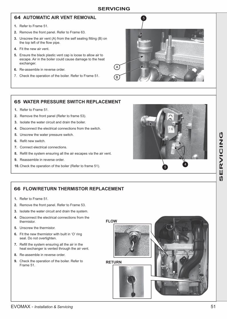
51EVOMAX - Installation & Servicing
SERVICING
64 AUTOMATIC AIR VENT REMOVAL
1. Refer to Frame 51.
2. Remove the front panel. Refer to Frame 63.
3. Unscrew the air vent (A) from the self sealing fitting (B) on the top left of the flow pipe.
4. Fit the new air vent.
5. Ensure the black plastic vent cap is loose to allow air to escape. Air in the boiler could cause damage to the heat exchanger.
6. Re-assemble in reverse order.
7. Check the operation of the boiler. Refer to Frame 51.
SE
RV
ICIN
G
65 WATER PRESSURE SWITCH REPLACEMENT1. Refer to Frame 51.
2. Remove the front panel (Refer to frame 53).
3. Isolate the water circuit and drain the boiler.
4. Disconnect the electrical connections from the switch.
5. Unscrew the water pressure switch.
6. Refit new switch.
7. Connect electrical connections.
8. Refill the system ensuring all the air escapes via the air vent.
9. Reassemble in reverse order.
10. Check the operation of the boiler (Refer to frame 51).
66 FLOW/RETURN THERMISTOR REPLACEMENT
1. Refer to Frame 51.
2. Remove the front panel. Refer to Frame 53.
3. Isolate the water circuit and drain the system.
4. Disconnect the electrical connections from the thermistor.
5. Unscrew the thermistor.
6. Fit the new thermistor with built in ‘O’ ring seal. Do not overtighten.
7. Refill the system ensuring all the air in the heat exchanger is vented through the air vent.
8. Re-assemble in reverse order.
9. Check the operation of the boiler. Refer to Frame 51.
FLOW
RETURN
5
A
B
45
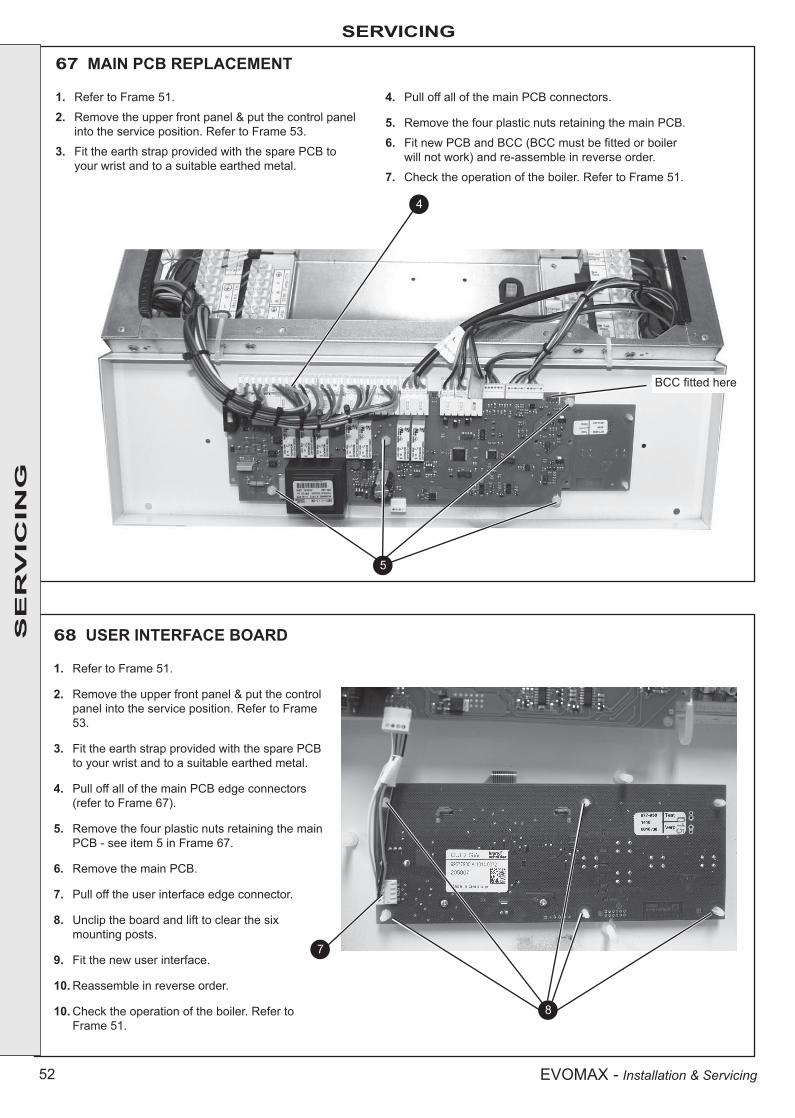
52 EVOMAX - Installation & Servicing
SERVICINGS
ER
VIC
ING
67 MAIN PCB REPLACEMENT
1. Refer to Frame 51.
2. Remove the upper front panel & put the control panel into the service position. Refer to Frame 53.
3. Fit the earth strap provided with the spare PCB to your wrist and to a suitable earthed metal.
4. Pull off all of the main PCB connectors.
5. Remove the four plastic nuts retaining the main PCB.
6. Fit new PCB and BCC (BCC must be fitted or boiler will not work) and re-assemble in reverse order.
7. Check the operation of the boiler. Refer to Frame 51.
4
68 USER INTERFACE BOARD
1. Refer to Frame 51.
2. Remove the upper front panel & put the control panel into the service position. Refer to Frame 53.
3. Fit the earth strap provided with the spare PCB to your wrist and to a suitable earthed metal.
4. Pull off all of the main PCB edge connectors (refer to Frame 67).
5. Remove the four plastic nuts retaining the main PCB - see item 5 in Frame 67.
6. Remove the main PCB.
7. Pull off the user interface edge connector.
8. Unclip the board and lift to clear the six mounting posts.
9. Fit the new user interface.
10. Reassemble in reverse order.
10. Check the operation of the boiler. Refer to Frame 51.
5
8
7
BCC fitted here
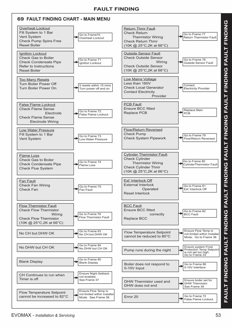
53EVOMAX - Installation & Servicing
FAULT FINDING
FA
ULT
FIN
DIN
G F
AU
LT
FIN
DIN
G F
AU
LT
FIN
DIN
G F
AU
LT
FIN
DIN
G F
AU
LT
FIN
DIN
G F
AU
LT
FIN
DIN
G
Overheat LockoutFill System to 1 BarVent SystemCheck Pump Spins FreeReset Boiler
69 FAULT FINDING CHART - MAIN MENU
Go to Frame70Overheat Lockout
Go to Frame 71Ignition Lockout
Too Many ResetsTurn Boiler Power OffTurn Boiler Power On
5 resets within 15 minsTurn power off and on
Go to Frame 72False Flame Lockout
Go to Frame 73Low Water Pressure
Go to Frame 74Flame Loss
Fan FaultCheck Fan WiringCheck Fan
Go to Frame 75Fan Fault
Return Thmr FaultCheck Return Thermistor WiringCheck Return Thmr(10K @ 25°C,2K at 66°C)
Go to Frame 77Return Thermistor Fault
Outside Sensor FaultCheck Outside Sensor WiringCheck Outside Sensor(10K @ 25°C,2K at 66°C)
Go to Frame 78Outside Sensor Fault
Low Mains VoltageLess than 160VCheck Local GeneratorContact Electricity Provider
ContactElectricity Provider
PCB FaultEnsure BCC fittedReplace PCB
Replace MainPCB
Flow/Return ReversedCheck PumpCheck System Pipework
Go to Frame 79Flow/Return Reversed
Cylinder Thermistor FaultCheck Cylinder Thermistor WiringCheck Cylinder Thmr(10K @ 25°C,2K at 66°C)
Go to Frame 80 CylinderThermistor Fault
Ext’ Interlock OffExternal Interlock OperatedReset Interlock
Go to Frame 81Ext’ Interlock Off
Ignition LockoutCheck Gas to BoilerCheck Condensate PipeRefer to InstructionsReset Boiler
False Flame LockoutCheck Flame Sense ElectrodeCheck Flame Sense Electrode Wiring
Low Water PressureFill System to 1 BarVent System
Flame LossCheck Gas to BoilerCheck Condensate PipeCheck Flue System
Flow Thermistor FaultCheck Flow Thermistor WiringCheck Flow Thermistor(10K @ 25°C,2K at 66°C)
Go to Frame 76Flow Thermistor Fault
BCC FaultEnsure BCC fitted correctlyReplace BCC
Go to Frame 82BCC Fault
No CH but DHW OKGo to Frame 83No CH but DHW OK
No DHW but CH OKGo to Frame 84No DHW but CH OK
Blank DisplayGo to Frame 85Blank Display
CH Continues to run when Timer is off
Ensure Night Setback not enabled. See Frame 37
Flow Temperature Setpoint cannot be increased to 82°C
Ensure Flow Temp is not limited within Installer Mode. See Frame 38
Flow Temperature Setpoint cannot be reduced to 80°C
Ensure Flow Temp is not limited within Installer Mode. Go to Frame 38
Pump runs during the nightEnsure system Frost Protection Temp Setpoint is not set too high. Go to Frame 33
Boiler does not respond to 0-10V Input
Go to Frame 860-10V Interface
DHW Thermistor used and DHW does not end
Error 20
Ensure boiler set for DHW ThermistorSee Frame 39
Go to Frame 72False Flame Lockout

54 EVOMAX - Installation & Servicing
FAULT FINDING FA
ULT
FIN
DIN
G F
AU
LT
FIN
DIN
G F
AU
LT
FIN
DIN
G F
AU
LT
FIN
DIN
G F
AU
LT
FIN
DIN
G F
AU
LT
FIN
DIN
G 70 OVERHEAT LOCKOUT
Has PCB just been replaced? Reset Boileryes
no
Are the boiler and CH/DHW system filled with water and are all isolation valves and radiator valves open?
Fill and vent the system and open all isolation valves, then reset the boiler.
no
yes
Is the flow/return differential across the boiler in excess of 30ºC?
Check the flow and return thermistors (refer to Frame 76 & 77)
no
yes
Check that the pump is rotating freely. Is the differential now below 20ºC?.
Replace the pump, then reset the boilerno
yesReset the boiler
71 IGNITION LOCKOUT
If the boiler is reset, does it ignite for a short time and then extinguish?
Check the detection electrode and associated harness for continuity, visual condition and position (refer to Frame 63). Check if the condensate pipe is blocked.
yes
no
Is the gas pressure available at the boiler > 18mbar? Check gas supply and rectify faultno
yes
Is the following voltage available at the Gas Valve? (approximately 215Vdc for 30, 40, 60, 80 and 150kW) (approximately 240Vac for 100 and 120kW)(* See note)
Check wiring from Gas Valve to PCB and replace if necessary, otherwise replace the main PCB
no
yes
Unplug the Gas Valve, is the resistance between the outside pins between 1kΩ and 10kΩ?
Replace Gas Valveno
yes
Check Spark Generator and associated Harness for continuity, visual condition and position (refer to Frame 54). Are these functioning correctly?
Replace Spark Generator and Harness as necessary
no
yes
Replace Ignition Electrode and associated Harness as necessary
noCheck Ignition Electrode and associated Harness for continuity, visual condition and position (refer to Frame 62). Are these functioning correctly?
yes
Replace Gas Valveno
Check Syphon and condensate drain pipework for blockage and rectify if necessary. Boiler now working OK?
* Note: due to the wave form of the rectified voltage, the reading will vary depending on the type of meter used to measure the value. In general terms a reading of greater than 150V indicates that the correct voltage is supplied to the gas valve.

55EVOMAX - Installation & Servicing
FAULT FINDING
FA
ULT
FIN
DIN
G F
AU
LT
FIN
DIN
G F
AU
LT
FIN
DIN
G F
AU
LT
FIN
DIN
G F
AU
LT
FIN
DIN
G F
AU
LT
FIN
DIN
G 72 FALSE FLAME LOCKOUT / ERROR 20
Check routing and integrity of internal boiler wiring is OK. Check condition of Flame Sense Electrode and replace if deteriorated.
yes
Reset the boiler, does boiler work OK?
no
Replace Flame Detection Electrode
Replace Water Pressure Switch
Check routing and integrity of internal boiler wiring
yes
yes
no
Disconnect the electrical connection to the Flame Sense Electrode. Is there continuity between the Electrode and earth?
73 LOW WATER PRESSURE
Fill and vent the system and open all Isolation Valves
noAre the boiler and CH system filled with water and all Isolation and Radiator Valves open?
yesEnsure wiring has continuity and is securely connected
no
Does the wiring from the Water Pressure Switch to the PCB have continuity and is it securely connected?
74 FLAME LOSSCheck the Detection Electrode and associated Harness for continuity, visual condition and position (refer to Frame 63). Check if the Condensate Pipe is blocked. Check if the Flue is blocked. Replace as necessary
yesIf the boiler is Reset, does the boiler Ignite for a short time and then Extinguish
no
Check Gas Supply and rectify faultnoIs the Gas Pressure available at the boiler > 18mBar?
yes
Is the following voltage available at the Gas Valve? (approximately 215Vdc for 30, 40, 60, 80 and 150kW) (approximately 240Vac for 100 and 120kW) (*See note)
Check wiring from Gas Valve to PCB and replace if necessary, otherwise replace the main PCB
no
yes
Check Spark Generator and associated Harness for continuity, visual condition and position (refer to Frame 54). Are these functioning correctly?
Replace Spark Generator and Harness as necessary
no
yes
Check Ignition Electrode and associated Harness for continuity, visual condition and position (refer to Frame 62). Are these functioning correctly?
Replace Ignition Electrode and associated Harness as necessary
no
yes
Check Syphon and condensate drain pipework for blockage and rectify if necessary. Boiler now working OK? Replace Gas Valve
no
* Note: due to the wave form of the rectified voltage, the reading will vary depending on the type of meter used to measure the value. In general terms a reading of greater than 150V indicates that the correct voltage is supplied to the gas valve

56 EVOMAX - Installation & Servicing
FAULT FINDING FA
ULT
FIN
DIN
G F
AU
LT
FIN
DIN
G F
AU
LT
FIN
DIN
G F
AU
LT
FIN
DIN
G F
AU
LT
FIN
DIN
G F
AU
LT
FIN
DIN
G 75 FAN FAULT
Rectify wiring & connectionsnoDoes the wiring from the Fan to the PCB have secure connections at both ends and has not deteriorated? Does the wiring have continuity?
yes
Replace main PCB
Replace Fan
no
yesIs there 230Vac at the blue and brown connections to the 3 way connection on the Fan?
76 FLOW THERMISTOR FAULT
Fit a new thermistornoDisconnect the electrical connection to the Flow Thermistor and check the resistance using a suitable multimeter connected across the thermistor’s terminal pins.At 25°C expect 9,700 - 10,300 ΩAt 60°C expect 2,400 - 2,600 ΩAt 85°C expect 1,000 - 1,100 ΩIs the thermistor value correct?
yes
Check and replace wiring as necessary
Replace main PCB
no
yesIs there continuity between the PCB and the Thermistor?
77 RETURN THERMISTOR FAULT
Fit a new thermistornoRemove the Return Thermistor from the CH return pipe and disconnect the wires. Check the resistance using a suitable multimeter connected across the thermistor’s terminal pins.At 25°C expect 9,700 - 10,300 ΩAt 60°C expect 2,400 - 2,600 ΩAt 85°C expect 1,000 - 1,100 ΩIs the thermistor value correct?
yes
Check and replace wiring as necessaryno
Is there continuity between the PCB and the Thermistor?
yes
Replace main PCB

57EVOMAX - Installation & Servicing
FAULT FINDING
FA
ULT
FIN
DIN
G F
AU
LT
FIN
DIN
G F
AU
LT
FIN
DIN
G F
AU
LT
FIN
DIN
G F
AU
LT
FIN
DIN
G F
AU
LT
FIN
DIN
G 78 OUTSIDE SENSOR FAULT
Fit a new outside sensorno
Disconnect the wires to the Outside Sensor. Check the resistance using a suitable multimeter connected across the thermistor’s terminal pins.At 0°C expect 32,000 - 33,000 ΩAt 10°C expect 19,000 - 21,000 ΩAt 20°C expect 12,000 - 13,000 ΩIs the thermistor value correct?
yes
Ensure the wiring has continuity and is securely connected
noDoes the Outside Sensor wiring between the boiler terminal strip and the PCB have continuity and is securely connected?
yes
Replace main PCB
Securely connect the wiring at both the boiler and Outside sensor
noIs the wiring securely connected at both the boiler and Outside Sensor?
yes
79 FLOW/RETURN REVERSED
Check that the system pipework is correct
Reverse Pumpno
Is the Pump connected the correct way?
yes

58 EVOMAX - Installation & Servicing
FAULT FINDING FA
ULT
FIN
DIN
G F
AU
LT
FIN
DIN
G F
AU
LT
FIN
DIN
G F
AU
LT
FIN
DIN
G F
AU
LT
FIN
DIN
G F
AU
LT
FIN
DIN
G 80 CYLINDER THERMISTOR FAULT
Fit a new cylinder thermistornoDisconnect the wires to the cylinder thermistor. Check the resistance using a suitable multimeter connected across the thermistor’s terminal pins.At 25°C expect 9,700 - 10,300 ΩAt 60°C expect 2,400 - 2,600 ΩAt 85°C expect 1,000 - 1,100 ΩIs the thermistor value correct?
yes
Ensure the wiring has continuity and is securely connected
no
Does the cylinder thermistor wiring between the boiler terminal strip and the PCB have continuity and is securely connected? Replace main PCB
Change menu setting for DHW Sensor to “Switched Live” (See Frame 32)
noIs a DHW Thermistor connected to the boiler?
yes
Securely connect the wiring at both the boiler and cylinder thermistor
noIs the wiring securely connected at both the boiler and cylinder thermistor?
yes
81 EXTERNAL INTERLOCK OFF
Is an External Interlock connected to the boiler?
yes
Has the External Interlock operated?
no
Does the wiring from the Interlock Relay (mounted within the boiler) to the terminal strip have continuity and is securely connected?
Replace the Interlock Relay Kit
Ensure that a link wire is securely connected across the terminals marked “External Interlock” in the boiler terminal strip
no
Reset the External Interlockyes
Ensure the wiring has continuity and is securely connected
no
yes
yes
82 BCC FAULT
Securely attach the correct BCC for the boiler onto the PCB.Note: ensure the correct orientation of the BCC by placing the side marked “TOP” upwards.
noIs the correct BCC for the boiler securely inserted into the slot at the front left of the PCB?(identified by the label on the BCC)
yes
Replace the BCC with a new BCC (that is correct for the boiler). After switching power on and resetting the boiler does the fault disappear
Replace main PCByes

59EVOMAX - Installation & Servicing
FAULT FINDING
FA
ULT
FIN
DIN
G F
AU
LT
FIN
DIN
G F
AU
LT
FIN
DIN
G F
AU
LT
FIN
DIN
G F
AU
LT
FIN
DIN
G F
AU
LT
FIN
DIN
G 83 NO CH BUT DHW OK
Set for Winter operation (see Frame 32)no
Is the boiler set for Winter operation?
yes
Are the Timer and Room Thermostat calling for Heat? Ensure that the Timer and Room Thermostat are calling for heat
no
yes
Are the Radiator Valves open? Open the Radiator Valvesno
yes
Is an OpenTherm device connected to the boiler (note that the Ideal Prog Room Stat is an OpenTherm device)?
Does the wiring from the boiler to the OpenTherm device have continuity?
yes
no
Rectify wiring from boiler to OpenTherm device
no
Is there 230Vac at (A)?There is no voltage from the Timer/Room Stat. This is not a boiler fault. Ensure voltage is supplied to the boiler by correcting external wiring
no
yes
Is there 230Vac at (B)? Check wiring from PCB to (B)no
yes
yes
Does wiring to external CH Pump have continuity and is to the correct connections?
Rectify wiring to external CH pumpno
yes
Is the CH pump stuck Replace the CH pumpno
yes
Free the pump
(B)
(A)
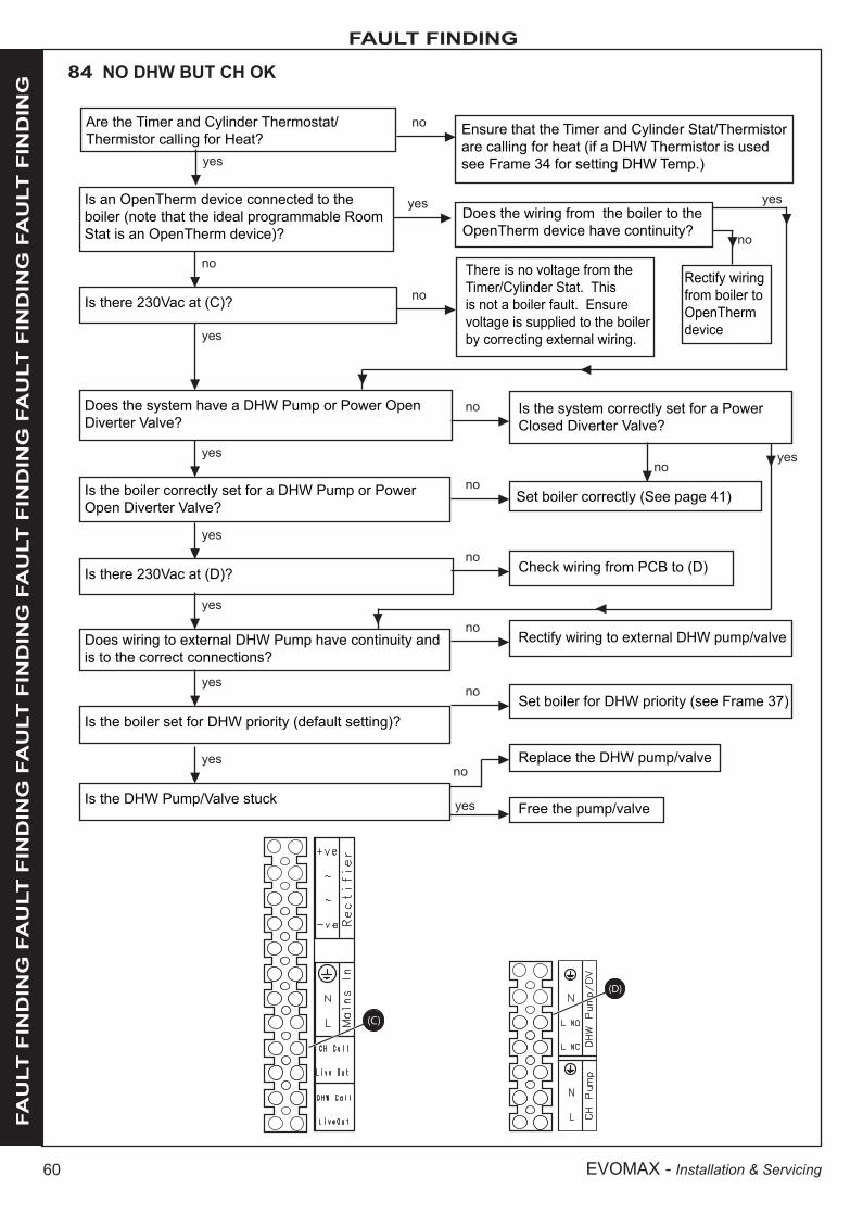
60 EVOMAX - Installation & Servicing
FAULT FINDING FA
ULT
FIN
DIN
G F
AU
LT
FIN
DIN
G F
AU
LT
FIN
DIN
G F
AU
LT
FIN
DIN
G F
AU
LT
FIN
DIN
G F
AU
LT
FIN
DIN
G 84 NO DHW BUT CH OK
Ensure that the Timer and Cylinder Stat/Thermistor are calling for heat (if a DHW Thermistor is used see Frame 34 for setting DHW Temp.)yes
Is there 230Vac at (C)?
There is no voltage from the Timer/Cylinder Stat. This is not a boiler fault. Ensure voltage is supplied to the boiler by correcting external wiring.
Rectify wiring from boiler to OpenTherm device
no
yes
Does the system have a DHW Pump or Power Open Diverter Valve?
Is the system correctly set for a Power Closed Diverter Valve?
no
no
Set boiler correctly (See page 41)
yes
Is there 230Vac at (D)? Check wiring from PCB to (D)no
yes
yes
Does wiring to external DHW Pump have continuity and is to the correct connections?
Rectify wiring to external DHW pump/valveno
yes
Is the DHW Pump/Valve stuck
Replace the DHW pump/valveno
(D)
(C)
yes
Is the boiler set for DHW priority (default setting)?Set boiler for DHW priority (see Frame 37)
no
Is the boiler correctly set for a DHW Pump or Power Open Diverter Valve?
no
yes
Is an OpenTherm device connected to the boiler (note that the ideal programmable Room Stat is an OpenTherm device)?
no
Does the wiring from the boiler to the OpenTherm device have continuity?
yes yes
no
Are the Timer and Cylinder Thermostat/Thermistor calling for Heat?
no
Free the pump/valveyes

61EVOMAX - Installation & Servicing
FAULT FINDING
FA
ULT
FIN
DIN
G F
AU
LT
FIN
DIN
G F
AU
LT
FIN
DIN
G F
AU
LT
FIN
DIN
G F
AU
LT
FIN
DIN
G F
AU
LT
FIN
DIN
G 85 NO DISPLAY
Supply power to the boilerno
Is there 230Vac to the boiler at (E)?
yes
(E)
yes
Connect the wiring from the terminal block to the main PCB securely
noIs the wiring from the boiler terminal block to the main PCB connected securely?
yesyes
Connect the cable from the main PCB to the user interface PCB securely
noIs the cable from the main PCB to the user interface PCB connected securely?
yesyes
Replace cable from main PCB to user interface PCB
noDoes the cable from the main PCB to the user interface PCB have continuity and is un-damaged?
yesyes
Check for shorts on Pumps/Diverter Valve/Fan/Spark Generator/Gas Valve and replace Fuse
noIs the Fuse on the main PCB OK?
yesyes
Replace main PCBno
Replace the user interface PCB, still no display?

62 EVOMAX - Installation & Servicing
FAULT FINDING FA
ULT
FIN
DIN
G F
AU
LT
FIN
DIN
G F
AU
LT
FIN
DIN
G F
AU
LT
FIN
DIN
G F
AU
LT
FIN
DIN
G F
AU
LT
FIN
DIN
G 86 0-10V INTERFACE
Set the boiler to accept a 0-10V input (see Frame 33)
noIs the boiler set to accept a 0-10V Input?
yesyes
Set the boiler to Winter Mode (see Frame 32)
noIs the boiler set to Winter Mode?
yesyes
Ensure between 2V and 10V is correctly connected to these terminals from the external device
noIs a voltage of between 2V and 10V being supplied to (F), with positive and negative connected correctly?
yesyes
Ensure that the wiring is securely connected and has continuity
noIs the wiring from the boiler terminal strip to the main PCB securely connected and has continuity?
yesyes
Replace main PCB
(F)

63EVOMAX - Installation & Servicing
SPARE PARTS
When replacing any part on this appliance use only spare parts that you can be assured conform to the safety and performance specification that we require. Do not use reconditioned or copy parts that have not been clearly authorised by Ideal. Failure to do so could affect safety or performance of this appliance.
Comprehensive spares parts information and details of approved Ideal Parts Distributors are available on www.idealparts.com
Our Parts team are also available to help with your Ideal Spare Parts enquiries on 01482 498665.
When calling, and to ensure we can provide you with the most accurate parts information, please ensure you have the following to hand;
- Boiler Model
- Appliance GC Number
- Boiler Serial Number

64 EVOMAX - Installation & Servicing
NOTES

65EVOMAX - Installation & Servicing
NOTES

Technical TrainingThe Ideal Technical Training Centre offers a series of first class training courses for domestic, commercial and industrial heating installers, engineers and system specifiers. For details of courses please ring: ........... 01482 498432
Ideal is a trademark of Ideal Boilers. Registered Office
Ideal Boilers Ltd., PO Box 103, National Avenue, Kingston Upon Hull, HU5 4JNTel 01482 492251 Fax 01482 448858
Registration No. London 322 137
Ideal Technical Helpline: 01482 498376Ideal Consumer Helpline: 01482 498376
www.idealcommercialboilers.com
Ideal Boilers Ltd. pursues a policy of continuing improvement in the design and performance of its products. The right is therefore reserved to vary specification without notice.